Embed Size (px)
Citation preview

12V/1A
GND
Digital signals
27V/0,9A
3,3V/20A
5V/20A
12V/20A
-12V/0,8A
-5V/2,5A
GND
5VSTB/3A
Line
Neutral
Earth
12V/3,5A
5V/1A
GND
Digital signals
5VSTB/1A
5V/1A
5VSTB/0,5A
GND
RS232 signals
Accessible by user !
Foot switch 2
Floorplan & Power Wiring BE3-R2 Chassis A, BE3-R1 Chassis D Bookeye Color Scanner
Mains
ATX-12V PC power supply
TG400-U33 400W Tagan
Power Input
100 – 240VAC47 – 63Hz 6A (115V)3A (230V)
ATX MotherboardD2151-S2
Siemens/Fujitsu
CCD camera boardS2N-H3-C
TTL input
Stepper motorPK243M-01B
VEXTRA
DC/DC converterIn 9 – 18V
Out 12V/15W
27V/1A
IO to PCI bridge PCB1
S2N-PCI-3-CImage Access
RUEF185
RUEF185
RUEF185
GND
Scanner chassis
RUEF185
Polyswitch resettable fuseRaychem, Tyco electronics
R1 Chassis DR2 Chassis A
All voltages are regulated.All currents are absolute maximum.
10.12.2008Version 1.4 R. Matthes
Foot switch 1TTL inputGND
Lamp left
27V/0,9AStepper motorPK243M-01B
VEXTRALamp right
27V/0,9AStepper motor
PK243-B1-SG18VEXTRA
CCD drive
Output: Motor 4Driver
ULN2003
RUEF185
Stepper motor
UBL23N08BIA 12V/0,2A
Output: Motor 3Driver chip A3979
Allegro
Output: Motor 2Driver chip A3979
Allegro
Output: Motor 1Driver chip A3979
Allegro
Input: IN2TTL level
Front panel
Left lamp
Right lamp
HeadHead
Head
Line
lase
r
BE3-R1/R2 Floor plan 1/2
FS-1
FS-2
COM2
Display unit
S2N-E-I2C-DIS-B
Cradle unit
S2N-E-I2C-8I-B
Keyboard unit
S2N-E-I2C-KBD-B
Coupler3101S
1
Digital signals
LANNetwork signals
VGA signals
VGA

27V/1,5A
GND
12V/4A
5V/1A
5VSTB/0,5A
Floorplan & Power WiringBE3-R2 Chassis A, BE3-R1 Chassis D Bookeye Color Scanner
Motherboardfrom previous page
DC/DC converterIn 9 – 18V
Out 12V/15W
27V/1A
IO to PCI bridge PCB2
S2N-PCI-3-C
Scanner chassis
R1 Chassis DR2 Chassis A
All voltages are regulated.All currents are max. rated.
TTL input
Craddle right
27V/1,5AStepper motor
PK266-02AVEXTRA
Craddle left
Output: Motor 2Driver chip A3979
Allegro
Output: Motor 1Driver chip A3979
Allegro
Left craddle lower positionInput: TTL
TTL input
Right craddle lower position
Stepper motorPK266-02A
VEXTRA
12V/7,5A
GND
Digital signal 8*Luxeon 4W
S2N-E-K2-DImage Access
Left lamp
Input: TTL
BE3-R1/R2 Floor plan 2/2
8*Luxeon 4W
S2N-E-K2-DImage Access
12V/7,5A
GND
Digital signal 8*Luxeon 4W
S2N-E-K2-DImage Access
Right lamp8*Luxeon 4W
S2N-E-K2-DImage Access
10.12.2008Version 1.4 R. Matthes
SATA 2,5" HD 40GBMHV2040BH
Fujitsu „Listed Accessory“
5V/1A
GND
Digital signals
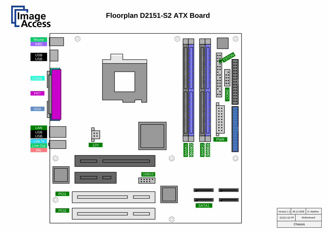
Floorplan D2151-S2 ATX Board
D2151-S2 FP Motherboard
Chassis
MouseKBD
USB
COM1
VGA
PRT
USB
USBLine In
Line OutMic
USB
SATA1
PCI1
PCI2
12VPWR
CO
M2
TSTON
BA
NK
1B
AN
K3
BA
NK
2B
AN
K4
LAN
09.12.2008Version 1.3 R. Matthes
USB1/2
In 1
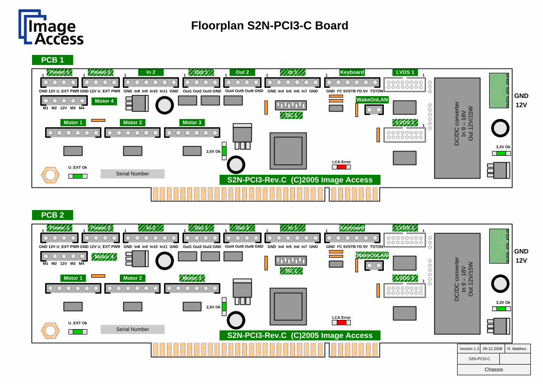
Serial Number
1
GND 12V U_EXT PWR
1 Power 2
GND 12V U_EXT PWR GND In8 In9 In10 In11 GND Out1 Out2 Out3 GND Out4 Out5 Out6 GND GND In4 In5 In6 In7 GND GND I²C 5VSTB I²D 5V TSTON
M1 M2 12V M3 M4
Power 1 In 2 Out 1 Out 2 In 1 Keyboard LVDS 1
DC
/DC
con
verte
rIn
9 –
18V
Out
12V
/15W
Motor 4
Motor 1 Motor 2 Motor 3
WakeOnLAN
1 1 1 1 1 1
1
DC 1
LCA Error
2,5V Ok
U_EXT Ok
3,3V Ok
S2N-PCI3-Rev.C (C)2005 Image Access09.12.2008Version 1.3 R. Matthes
S2N-PCI3-C
Chassis
Floorplan S2N-PCI3-C Board
GND12V
LVDS 2
Serial Number
1
GND 12V U_EXT PWR
1 Power 2
GND 12V U_EXT PWR GND In8 In9 In10 In11 GND Out1 Out2 Out3 GND Out4 Out5 Out6 GND GND In4 In5 In6 In7 GND GND I²C 5VSTB I²D 5V TSTON
M1 M2 12V M3 M4
Power 1 In 2 Out 1 Out 2 Keyboard LVDS 1
DC
/DC
con
verte
rIn
9 –
18V
Out
12V
/15W
Motor 4
Motor 1 Motor 2 Motor 3
WakeOnLAN
1 1 1 1 1 1
1
DC 1
LCA Error
2,5V Ok
U_EXT Ok
3,3V Ok
S2N-PCI3-Rev.C (C)2005 Image Access
GND12V
LVDS 2
PCB 1
PCB 2

09.12.2008Version 1.3 R. Matthes
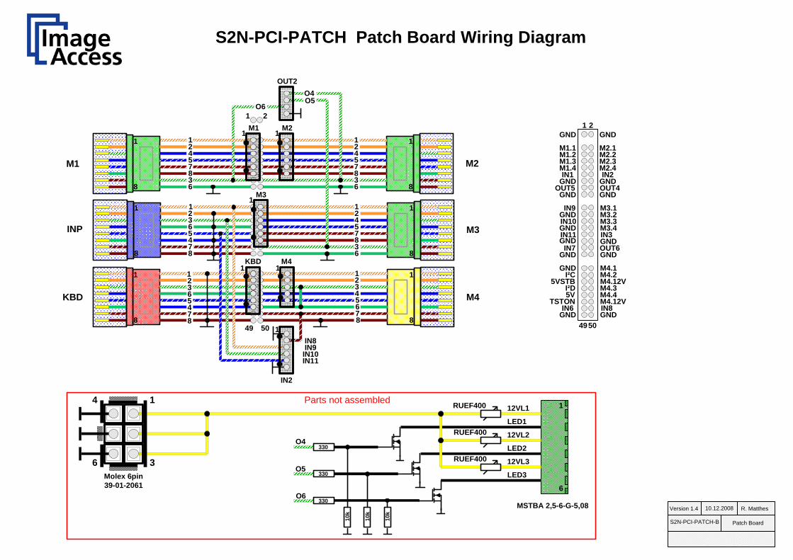
S2N-PCI-PATCH-A/B
Chassis
S2N-PCI-PATCH-A
KBDINP OBJ LR LL CCD
Keyboard 1 In 2 1 Motor 1 1 Out 2 1
1Motor 2Motor 3 1Motor 4 1
LAMP
Floorplan S2N-PCI-PATCH-A/B Board
1
3
4
6
PCI 12V
5V STB
S2N-PCI-PATCH-B
KBDINP OBJ LR LL CCD
Keyboard 1 In 2 1 Motor 1 1 Out 2 1
1Motor 2Motor 3 1Motor 4 15V VCC
12V M4

BE3-R2 Chassis A, BE3-R1 Chassis D Wiring Diagram Base Unit
10.12.2008Version 1.4 R. Matthes
BE3-R1/R2 Base Unit
Chassis
Left Lamp
PCB1 of 2S2N-PCI3-C
Right Lamp
6*AWG24
250mm
Motor 1
BE3-K-50-A
Neck / Head
OUT 2
1
Neck / Head
LVDS IN1 Neck Connector
Foot switch 1PK266-02A VEXTRA
Cradle Right
6 x AWG24 UL
500mm
Motor 2
1
PK266-02A VEXTRA
Cradle Left
6 x AWG24 UL
500mm
Motor 1
1
PCB2 of 2S2N-PCI3-C
AMP 6pin 826363-6
AMP 6pin 826363-6
BE3-K-52-A
BE3-K-31-A
BE3-K-31-A
BE3-K-38-A
S2N-PCI-PATCH-A/B
1
6*AWG24
250mm
Motor 2
BE3-K-50-A1
1
6*AWG24
250mm
Motor 3
BE3-K-50-A1
1
6*AWG24
250mm
Motor 4
BE3-K-51-A1
1
6*AWG24
250mm
IN2
BE3-K-50-A1
1
1
14*AWG24
250mm
Foot switch 2
6*AWG24
250mm
KBD
BE3-K-50-A1
1
BE3-K-32-A500mm
3101S
3101S
1000mm
1000mm
PATCHK6-SFTP-GR-1M
1
8
1
8
1
8
1
8
1
8
1
8
1
8
230mm

GNDS2N1
10.12.2008Version 1.4 R. Matthes
BE3-R1/R2 TG400-U33
Chassis
Molex 24pin 39-01-2245Not shown
First PCB
SATA PowerNot shown
PHONIX CONTACT MSTB-2,5/4-ST-5.08
Second PCB
S2N-PCI3-CS2N-PCI3-C
ATX MotherboardD2151-S2
Siemens/Fujitsu
BE3-R2 Chassis A, BE3-R1 Chassis D Wiring Diagram ATX Power & Board
TG400-U33 Power Supply400W Tagan
3,3V / 20A5V / 20A12V / 28A-12V 0,8A-5V / 1A
5VSTB / 3A
100 – 240VAC400W
450mm
450mm
450mm
AMP 2pin 826363-2
AMP 2pin 826363-2
Wake On LAN
TSTON
COM2 COM 2 900mm
2xPCIExpress
200mm
BE3-K-30-A
BE3-K-30-A
BE3-K-06A
3 x 12V
3 x GND
450mm
2 x 12V2 x GND
1
3
4
6
12VL2
12VL1 GNDL1
GNDL2
Molex 6pin 39-01-2061
12VS2N1
BE3-K-30-A
1
3
4
6
12VR2
12VR1 GNDR1
GNDR2
Molex 6pin 39-01-2061
GNDS2N212VS2N2
12VS2N2
GNDS2N2
PHONIX CONTACT MSTB-2,5/4-ST-5.08BE3-K-30-A
12VS2N1
GNDS2N1
5V STDBY
23xATXPWR
ON
1
1
320mmBase Unit
Coupler3101S
RJ45
LAN
1 1
Network Port
500mm
PATCHK6-SFTP-BL-1M
Left Lamp
1
2
3
4
12VR1
12VR2GND
GND
Right Lamp
1
2
3
4
12VL1
12VL2GND
GND
Molex 4pin 39-01-2041
VGA VGASVGA2MF
1800mm
600mm
600mm
600mm
600mm
BS2-F-K-09-A
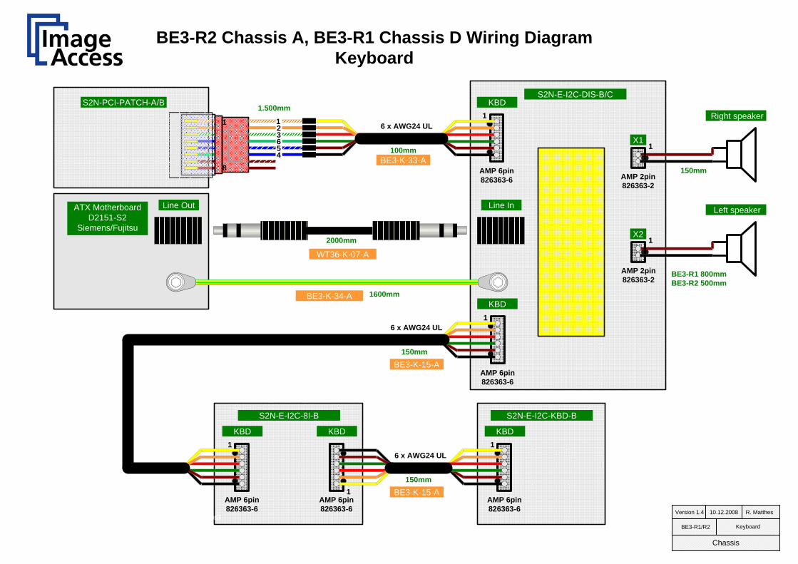
BE3-R2 Chassis A, BE3-R1 Chassis D Wiring Diagram Keyboard
S2N-E-I2C-DIS-B/C
Right speaker
BE3-K-33-A
6 x AWG24 UL
100mm
1
AMP 6pin 826363-6
KBD
AMP 2pin 826363-2
1X1
Left speaker
1X2
AMP 2pin 826363-2
BE3-K-15-A
6 x AWG24 UL
150mm
1
AMP 6pin 826363-6
KBD
PCI-1 Motor3
1
AMP 6pin 826363-6
KBD
BE3-K-15-AAMP 6pin 826363-6
6 x AWG24 UL
150mm
KBD
1
1
AMP 6pin 826363-6
KBD
S2N-E-I2C-8I-B S2N-E-I2C-KBD-B
10.12.2008Version 1.4 R. Matthes
BE3-R1/R2 Keyboard
Chassis
Line OutATX MotherboardD2151-S2
Siemens/Fujitsu
Line In
WT36-K-07-A
2000mm
1600mm
8
1 123
456
S2N-PCI-PATCH-A/B 1.500mm
BE3-K-34-A
150mm
BE3-R1 800mmBE3-R2 500mm

UBL23N08BIASaia Burgess
RJ45 Coupler 3101S1
8
10.12.2008Version 1.4 R. Matthes
BE3-R1/R2 Head & Neck
Focus Motor
500mmLoop r > 20mm
Focus Switch BE3-K-35-A
PK243A1A-SG18VEXTRA
RJ45 Coupler 3101S
8
1
Lense Carrier Switch
Lense Carrier Motor
16pin header 16 x AWG28Twisted pair
BE3-R1 2.000mmBE3-R2 1.500mm
S2N-H3-C
RJ451
8
1
8
RJ458*AWG26 shielded
2.000mm
PATCHK6-SFTP-GE-2M
RJ451
8
1
8
RJ458*AWG26 shielded
2.000mm
BE3-K-37-A
BE3-R2 Chassis A, BE3-R1 Chassis D Wiring Diagram Head & Neck
Line laserLFL650-5-12(9x20)60
JST SM 2pin
1
JST SM 8pin
S2N-E-LAS1-B
2 x AWG24 UL sw
300mmAMP 2pin 826363-2
1X2
AMP 2pin 826363-2
X1
8*AWG26 shielded
BE3-K-11-A
PATCHK6-SFTP-GR-2M
BE3-K-36-A
16pin header
1
WE 7427227
BE3-K-11-A
400 mm
shrink tubingFerrit
1
JST SM 2pin

PK243M-01AVEXTRA
BE3-L2-B Wiring Diagram Lamp
Lamp home position
1
2
3
4
12VR1
12VR2GND
GND
Molex 4pin 39-01-2040
S2N-E-K2-C
AWG18 silicone
AWG18 silicone
AWG24 silicone
S2N-E-K2-C
AWG18 silicone
AWG18 silicone
RJ45
8
1Lamp Motor
8*AWG26 shielded
900mm
09.12.2008Version 1.3 R. Matthes
BE3-L2-B Lamp for BE3-R1/2
GND
+12V
GND
+12V
+12V
+12V
GND
GND
Lamp Beam
BE3-K-40-A
Extend cable 250mm over beam end
Extend cable 250mm over beam end
100mm
200mm
500mm
150mm

PK243M-01AVEXTRA
BE3-L2-C Wiring Diagram Lamp
Lamp home position
1
2
3
4
12VR1
12VR2GND
GND
Molex 4pin 39-01-2040
S2N-E-K2-D/E
AWG18 silicone
AWG18 silicone
AWG24 silicone
S2N-E-K2-D/E
AWG18 silicone
AWG18 silicone
RJ45
8
1Lamp Motor
8*AWG26 shielded
900mm
10.12.2008Version 1.4 R. Matthes
BE3-L2-C
Enhanced thermal contact
Lamp BE3-R1/2
GND
+12V
GND
+12V
+12V
+12V
GND
GND
Lamp Beam
BE3-K-40-A
Extend cable 250mm over beam end
Extend cable 250mm over beam end
100mm
200mm
500mm
150mm
1 nF
twistw
edtw
istwed
snap ferrit
WE 742 711 32
Rod Core Inductor WE-SDWE 744 710 205
Rod Core Inductor WE-SDWE 744 710 205
1 nF
M1
8
1 1
8
1
8
1
8
1
1
1
1
8
11
M2
M3
M4KBD
OUT2
M1 M2
M3
M4KBD8
1
IN2
1 2
49 50
INP
1
2
3
45
6
78
12
3
45
6
78
12
3
45
6
78
12345678
123
456
78
123
456
78
1
GND GND
M1.1 M2.1M1.2 M2.2M1.3 M2.3M1.4 M2.4
OUT5 OUT4GND GND
M3.1
M4.1
M3.2
M4.2
M3.3
M4.12V
M3.4
M4.3
OUT6
IN8
GND
GND
IN1 IN2GND GND
IN3
M4.4
GND
M4.12V
GND
IN9
I²C
GND
5VSTB
IN10
I²D
GND
IN6
IN7
GND
GND
5V
IN11
TSTON
GND
1 2
4950
10.12.2008Version 1.4 R. Matthes
S2N-PCI-PATCH-B Patch Board
S2N-PCI-PATCH Patch Board Wiring Diagram
1
6
12VL1
LED1
12VL2
LED2
12VL3
LED3
MSTBA 2,5-6-G-5,08
O4
O6O5
O6
O5
O4
6
4
3
1 RUEF400
Molex 6pin 39-01-2061
RUEF400
RUEF400
330
330
330
10k
10k
10k
Parts not assembled
IN8IN9
IN10IN11


![CA…Author tmt Subject [global] dpi_mode= flexible dpi=300 scanmode=wait colormode=truecolor docmode=3 docheight = 0 wa_x = 1 wa_y = 1 serial=BE3-SGS-R2-0019994330ac FirmwareVersion=5.20](https://img.pdfslide.us/doc/110x75/5e56c8360997d632026d74f5/ca-author-tmt-subject-global-dpimode-flexible-dpi300-scanmodewait-colormodetruecolor.jpg)


![11…J155 ycc . Author: davidc Subject [global] dpi_mode= flexible dpi = 300 scanmode=wait colormode=truecolor docmode=3 docheight = 0 wa_x = 1 wa_y = 1 serial=BE3-SGS-R2-0019994330ac](https://img.pdfslide.us/doc/110x75/60fe4e2967192074a87e5baf/11-j155-ycc-author-davidc-subject-global-dpimode-flexible-dpi-300-scanmodewait.jpg)