Embed Size (px)
Citation preview
1
FLOOR VIBRATIONS DUE TO HUMAN ACTIVITIES:
Tools and Tips for Satisfactory Designs
Christopher H. Raebel, Ph.D., P.E., S.E.
Assistant Professor of Civil and Architectural Engineering
Milwaukee School of Engineering
Milwaukee, WI
September 12, 2012 www.LearnWithSEU.com
Presentation Overview
� Introduction
� Floor vibration basics
� Design practices
� Brief Q&A time
� Case study: Kunkle Lounge at Penn State
� Basic computer modeling for vibrations
� Q&A (please ask questions throughout!)
This presentation will focus on steel framed floors, but
many principles may be applied to other framing systems2
About Your Speaker
� Assistant Professor, Civil & Architectural Engr.
� >10 years experience in private practice
� Education:
� B.S. Architectural Engineering, MSOE, 1994
�M.S. Architectural Engineering, Penn State, 2000
� Thesis: “Development of an Experimental Protocol for Floor
Vibration Assessment”
� Ph.D. Civil Engineering, Marquette, 2011
� Dissertation: “A Quantitative Study of Robustness
Characteristics of Steel Framed Structures
� Licensed P.E., S.E.3
2
Why are we talking about this?
� Floor vibrations continue to be common
� “Efficient” designs present new problems
…vibrations!
� Lightweight concrete
� “Stronger” steel
� Design techniques continue to improve based
on new research
4
Presentation Overview
� Introduction
� Floor vibration basics
� Design practices
� Brief Q&A time
� Case study: Kunkle Lounge at Penn State
� Basic computer modeling for vibrations
� Q&A (please ask questions throughout!)
5
Floor vibration basics
� Why are vibrations objectionable?
�Our bodies are not comfortable when they’re
vibrating!
� When are vibrations objectionable?
�When our internal organs go into resonance
� This occurs when the floor has a fundamental natural
frequency of approx. 7 Hz.
� Will the floor collapse?
� Strength and serviceability are different things
6
3
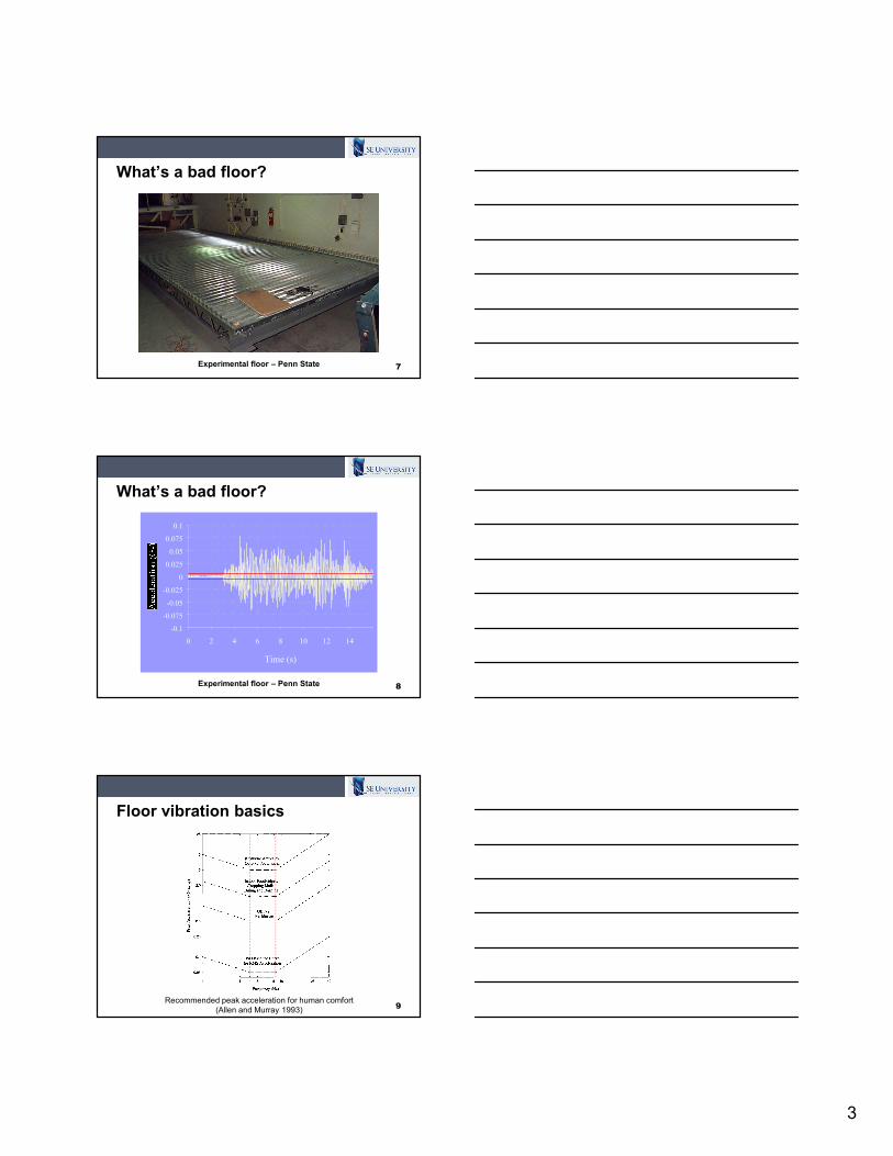
What’s a bad floor?
7Experimental floor – Penn State
What’s a bad floor?
8Experimental floor – Penn State
-0.1
-0.075
-0.05
-0.025
0
0.025
0.05
0.075
0.1
0 2 4 6 8 10 12 14
Time (s)
Floor vibration basics
9Recommended peak acceleration for human comfort
(Allen and Murray 1993)
4
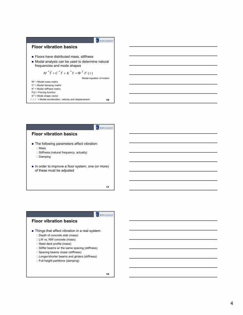
Floor vibration basics
� Floors have distributed mass, stiffness
� Modal analysis can be used to determine natural
frequencies and mode shapes
Modal equation of motion
M* = Modal mass matrix
C* = Modal damping matrix
K* = Modal stiffness matrix
F(t) = Forcing function
ΦT = Mode shape vector
= Modal acceleration, velocity and displacement 10
)(***tFYKYCYM
TΦ=++ &&&
YYY ,, &&&
Floor vibration basics
� The following parameters affect vibration:
�Mass
� Stiffness (natural frequency, actually)
�Damping
� In order to improve a floor system, one (or more)
of these must be adjusted
11
Floor vibration basics
� Things that affect vibration in a real system:
�Depth of concrete slab (mass)
� LW vs. NW concrete (mass)
� Steel deck profile (mass)
� Stiffer beams w/ the same spacing (stiffness)
� Spacing beams closer (stiffness)
� Longer/shorter beams and girders (stiffness)
� Full height partitions (damping)
12
5
Floor vibration basics
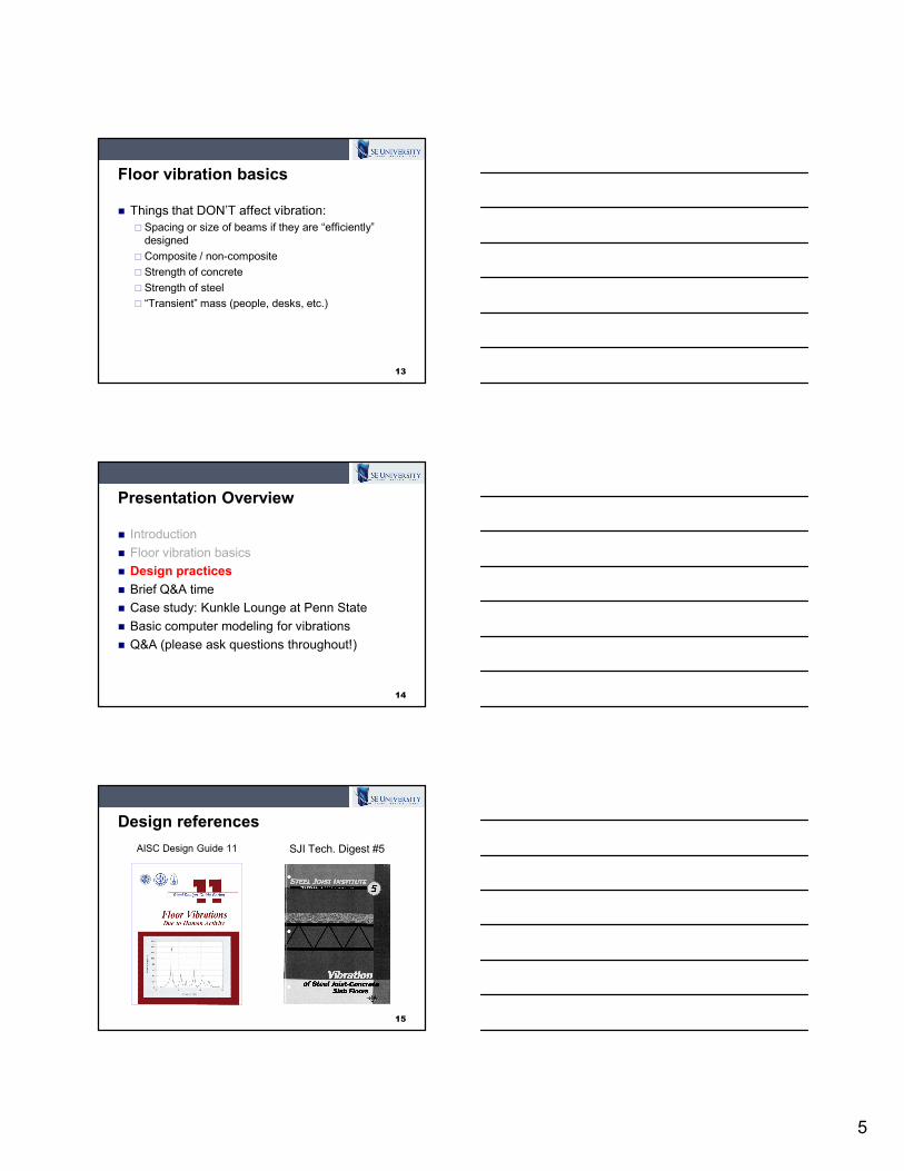
� Things that DON’T affect vibration:
� Spacing or size of beams if they are “efficiently”
designed
�Composite / non-composite
� Strength of concrete
� Strength of steel
� “Transient” mass (people, desks, etc.)
13
Presentation Overview
� Introduction
� Floor vibration basics
� Design practices
� Brief Q&A time
� Case study: Kunkle Lounge at Penn State
� Basic computer modeling for vibrations
� Q&A (please ask questions throughout!)
14
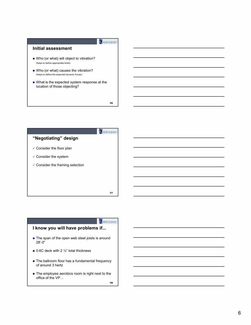
Design references
15
AISC Design Guide 11 SJI Tech. Digest #5
6
Initial assessment
� Who (or what) will object to vibration?
(helps to define appropriate limits)
� Who (or what) causes the vibration?(helps to define the expected dynamic forces)
� What is the expected system response at the
location of those objecting?
16
“Negotiating” design
� Consider the floor plan
� Consider the system
� Consider the framing selection
17
I know you will have problems if...
� The span of the open web steel joists is around
28’-0”
� 0.6C deck with 2 ½” total thickness
� The ballroom floor has a fundamental frequency
of around 3 hertz
� The employee aerobics room is right next to the
office of the VP…
18
7
“System-based” approach
� Slab assumed to continue to adjacent bays
� Mass (weight) and stiffness determined on a
“panel” basis
� We assume fundamental frequency participates
the most (others negligible)
� Assume composite action
� Continuity and cantilevers are considered
19
What about damping?
� Architectural
elements provide
most damping
� Full height partitions?
Use 3% damping
(0.03)
� Use 2% (0.02) for
most other scenarios
20(Tedesco et. al 1999)
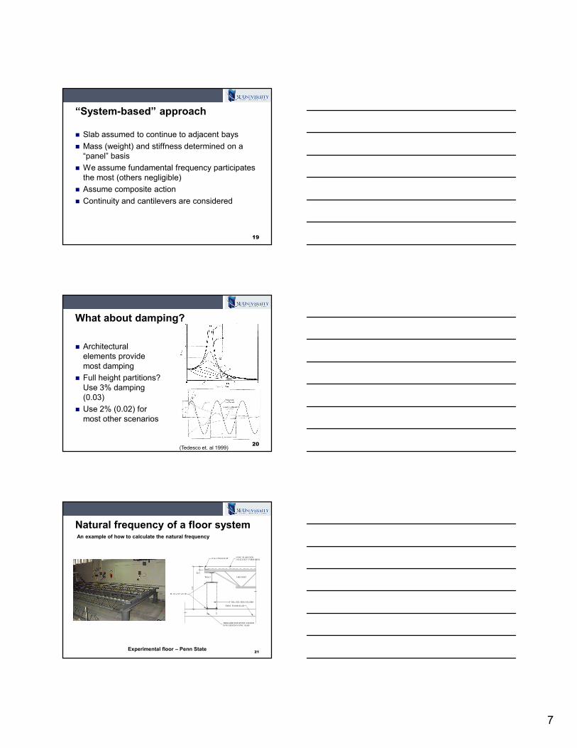
Natural frequency of a floor system
21
14K4 JOISTW8x13
12 GA. POUR STOP
PL 3/4 x 10" x 0'-10"
EXIST. FLOOR SLAB
THREADED ROD EPOXY ANCHOR
INTO EXISTING CONC. SLAB
8" DIA. STD. PIPE COLUMN
CONC. SLAB OVER
1.0C22 GALV. FORM DECK
3'-0"
21 2"
Experimental floor – Penn State
An example of how to calculate the natural frequency
8
Natural frequency of a floor system
22
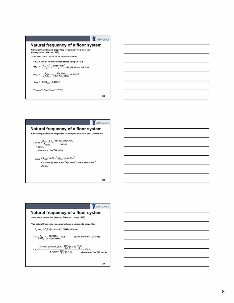
Calculating estimated properties for an open web steel joist
(Hanagan and Murray 1997)
14K4 joist, 26’-0” span, 30 in. center-to-center
• wTL = 251 plf (from SJI load tables using 26’-0”)
•MALL =
•ABOT =
•ATOP =
•ACHORD =
( )( ) ( )( )22
TL251plf 26 ftw L
= =21,209.5 ft-lb =254.5 in-k8 8
( )( ) ( )( )2ALL
ALL
M 254.5in-k= =0.653in14 in.-1in. 30ksid-1 f
2BOT
1.25A =0.816in
2BOT TOP
A +A =1.469in
Natural frequency of a floor system
23
Calculating estimated properties for an open web steel joist (continued)
•
•
( )( ) ( )2BOT
2CHORD
0.653in 14in.-1in.A d-1y =0.5 + =
A 1.469in
=6.28in.
(down from the T.O. joist)
( )( ) ( )( )( ) ( )( )
2 2
CHORD TOP BOT
2 22
4
I = A y-0.5in. + A d-y-0.5 in.
= 0.816in 6.28in.-0.5 in. + 0.653in. 14 in.-6.28in.-0.5 in.
=61.3in
Natural frequency of a floor system
24
Joist mode properties (Murray, Allen and Ungar 1997)
The natural frequency is calculated using composite properties
•
•
•
( )1.5
1.5cC C
E = w f' (ksi) = 145pcf 3ksi =3,024ksi
( )( )S
C
E 29,000ksin= = =7.11.35E 1.35 3,024ksi
(down from the T.O. joist)
( ) ( )
( )
2
c2
30in. 1.5 in.1.469in 1.0in.+6.28in. - 1.5 in.7.1 2
y = =0.76in.30in.1.469in + 1.5in.7.1
(down from the T.O. deck)
9
Natural frequency of a floor system
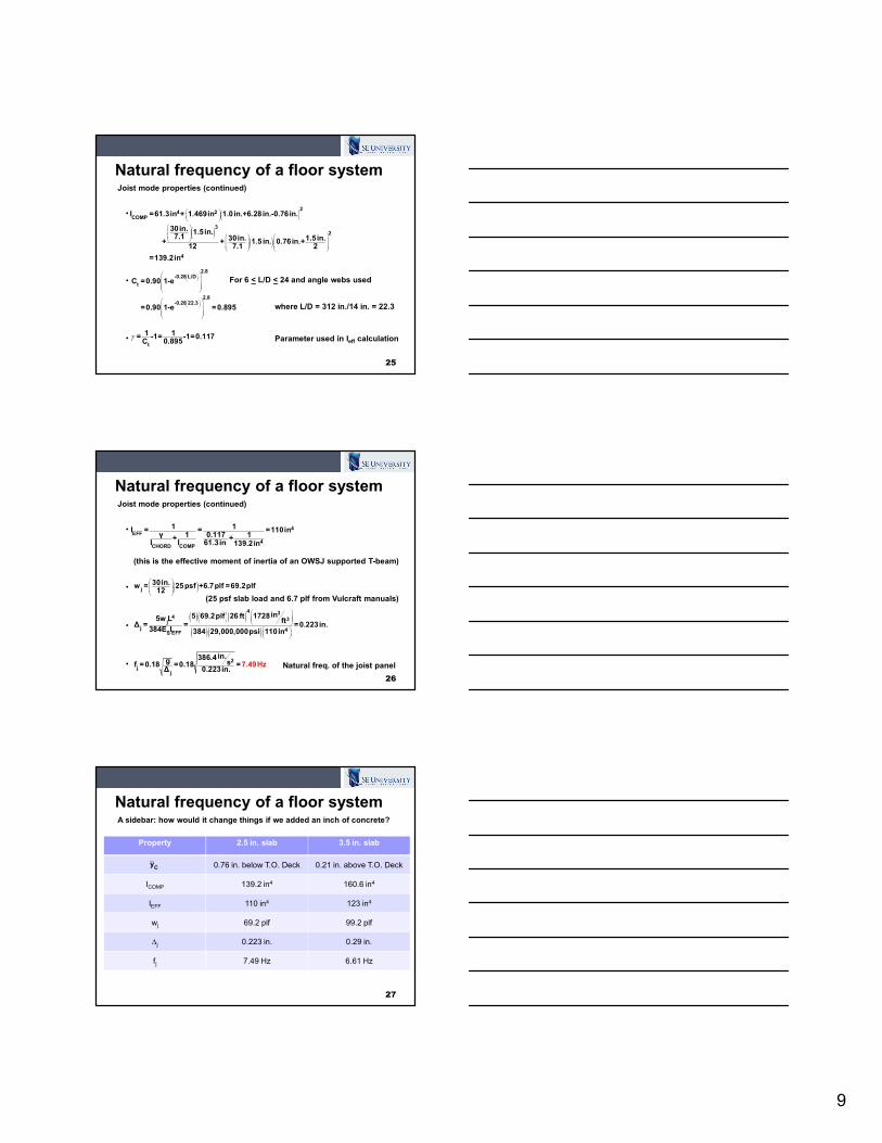
25
Joist mode properties (continued)
•
•
•
( )
( )( )
24 2
COMP
32
4
I =61.3in + 1.469in 1.0in.+6.28in.-0.76in.
30in. 1.5in.7.1 30in. 1.5in. + + 1.5 in. 0.76in.+
12 7.1 2
=139.2in
2.8-0.28 L/D
t
2.8-0.28 22.3
C =0.90 1-e
=0.90 1-e =0.895
where L/D = 312 in./14 in. = 22.3
For 6 < L/D < 24 and angle webs used
t
1 1= -1= -1=0.1170.895C
γ Parameter used in Ieff calculation
Natural frequency of a floor system
26
Joist mode properties (continued)
•
•
•
•
4EFF
4CHORD COMP
1 1I = = =110inγ 1 0.117 1+ +
I I 61.3in 139.2in
(this is the effective moment of inertia of an OWSJ supported T-beam)
( )j30in.w = 25 psf +6.7plf =69.2plf
12
(25 psf slab load and 6.7 plf from Vulcraft manuals)
( )( )( )( )( )
4 34 3
jj 4
EFFS
in5 69.2plf 26 ft 17285w L ft∆ = = =0.223in.
384E I 384 29,000,000psi 110in
2
jj
in.386.4g sf =0.18 =0.18 =∆ 0.
722
.3in.
49Hz Natural freq. of the joist panel
Natural frequency of a floor system
27
A sidebar: how would it change things if we added an inch of concrete?
Property 2.5 in. slab 3.5 in. slab
0.76 in. below T.O. Deck 0.21 in. above T.O. Deck
ICOMP 139.2 in4 160.6 in4
IEFF 110 in4 123 in4
wj 69.2 plf 99.2 plf
∆j 0.223 in. 0.29 in.
fj 7.49 Hz 6.61 Hz
Cy
10
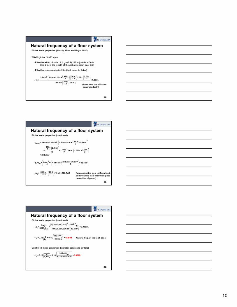
Natural frequency of a floor system
28
Girder mode properties (Murray, Allen and Ungar 1997)
W8x13 girder, 10’-0” span
• Effective width of slab: 0.2Lg = (0.2)(120 in.) + 6 in. = 30 in.
(the 6 in. is the length of the slab extension past C/L)
• Effective concrete depth: 2 in. (incl. conc. in flutes)
•
( )
( )
2
c2
7.99in. 30in. 2.0in.3.84 in 0.5 in.+2.5 in.+ - 2.0in.2 7.1 2
y = =1.50in.30in.3.84 in + 2.0in.7.1
(down from the effective
concrete depth)
Natural frequency of a floor system
29
Girder mode properties (continued)
•
•
•
( )( )
2
4 2COMP
32
4
7.99in.I =39.6in + 3.84in 0.5 in.+2.5in.+ -1.50in.2
30in. 2.0in.7.1 30in. 2.0in. + + 2.0in. 1.50in.+
12 7.1 2
=211.2in
4 44 4COMP NC
g NC
I -I 211.2in -39.6inI =I + =39.6in + =82.5 in4 4
g69.2plf 27 ftw = +13plf =386.7plf
22.5 ft
(approximating as a uniform load,
and includes slab extension past
centerline of girder)
Natural frequency of a floor system
30
Girder mode properties (continued)
•
•
•
( )( )( )( )( )
4 34 3
jj 4
EFFS
in5 386.7plf 10 ft 17285w L ft∆ = = =0.036in.
384E I 384 29,000,000psi 82.5in
2
gg
in.386.4g sf =0.18 =0.18 =∆ 0.
103
86in.
.6Hz Natural freq. of the joist panel
Combined mode properties (includes joists and girders)
2
ggj
in.386.4g sf =0.18 =0.18 =∆ +∆ 0.223in.+.036in.
6.95Hz
11
It’s halftime!
31
Do you have any questions
on the material so far?
Presentation Overview
� Introduction
� Floor vibration basics
� Current design practices
� Brief Q&A time
� Case study: Kunkle Lounge at Penn State
� Basic computer modeling for vibrations
� Q&A (please ask questions throughout!)
32
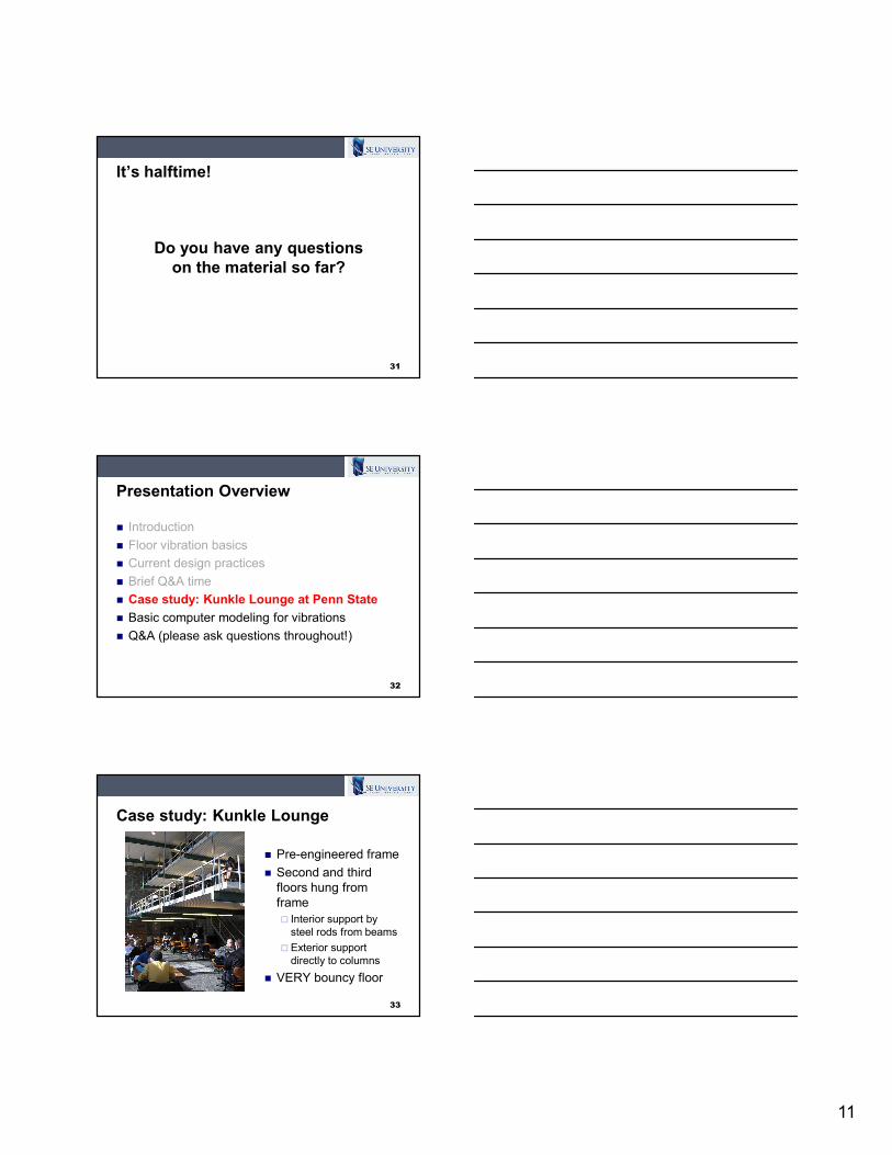
Case study: Kunkle Lounge
33
� Pre-engineered frame
� Second and third
floors hung from
frame
� Interior support by
steel rods from beams
� Exterior support
directly to columns
� VERY bouncy floor
12
Case study: Kunkle Lounge
34
Case study: Kunkle Lounge
35
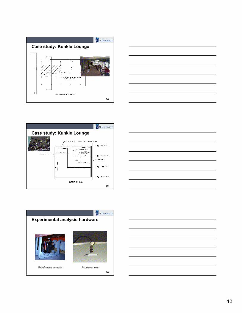
Experimental analysis hardware
36
Proof-mass actuator Accelerometer

13
Acceleration response
37
-0.035
-0.03
-0.025
-0.02
-0.015
-0.01
-0.005
0
0.005
0.01
0.015
0.02
0.025
0.03
0.035
0 1 2 3 4 5 6 7 8
Accele
rati
on
(g
)
Time (sec)
Frequencies and mode shapes
38
Mode 1: 7.08 Hz
ζ = 3.24%Mode 2: 7.63 Hz
ζ = 1.02%Mode 3: 8.96 Hz
ζ = 1.59%Mode 4: 10.66 Hz
ζ = 0.50%
(Excitation centered on the floor)
Frequencies and mode shapes
39
Mode 1: 7.09 Hz Mode 2: 7.62 Hz Mode 3: 8.96 Hz Mode 4: 10.66 Hz
(Excitation offset from center)
14
Results from Kunkle floor testing
� Clearly the floor is not within allowable limits per
DG #11
� Several natural frequencies within the “danger
zone”
� Active control tried to minimize vibration
� Proof-mass actuator used
� Floor was noticeably “stiffer” when actuator tuned to
the floor’s vibration
40
Presentation Overview
� Introduction
� Floor vibration basics
� Current design practices
� Brief Q&A time
� Case study: Kunkle Lounge at Penn State
� Basic computer modeling for vibrations
� Q&A (please ask questions throughout!)
41
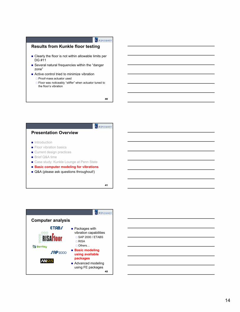
Computer analysis
42
� Packages with
vibration capabilities
� SAP 2000 / ETABS
�RISA
�Others…
� Basic modeling
using available
packages
� Advanced modeling
using FE packages
15
Computer analysis
43
-0.1
-0.075
-0.05
-0.025
0
0.025
0.05
0.075
0.1
0 2 4 6 8 10 12 14
Time (s)
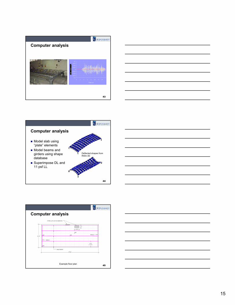
Computer analysis
� Model slab using
“plate” elements
� Model beams and
girders using shape
database
� Superimpose DL and
11 psf LL
44
Deflected shapes from
RISA-3D
Computer analysis
45
059
069
005
001
27'-0"
11'-0"
2'-6" C/C JOISTS
TYPICAL PLATE ELEMENTS
2'-2"
1'-3"
14K4 JOISTS
W8X13
W8X13
Example floor plan
16
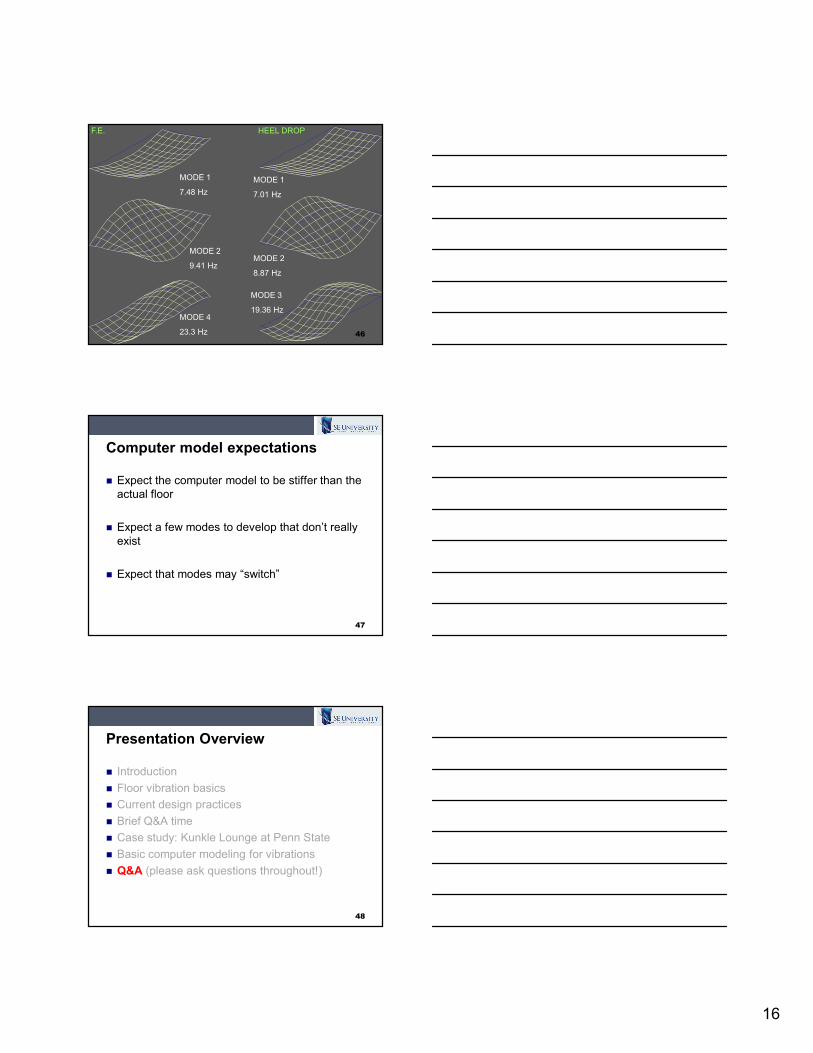
46
MODE 1
7.48 Hz
MODE 2
9.41 Hz
MODE 4
23.3 Hz
MODE 1
7.01 Hz
MODE 2
8.87 Hz
MODE 3
19.36 Hz
F.E. HEEL DROP
Computer model expectations
� Expect the computer model to be stiffer than the
actual floor
� Expect a few modes to develop that don’t really
exist
� Expect that modes may “switch”
47
Presentation Overview
� Introduction
� Floor vibration basics
� Current design practices
� Brief Q&A time
� Case study: Kunkle Lounge at Penn State
� Basic computer modeling for vibrations
� Q&A (please ask questions throughout!)
48
17
References and acknowledgments
49
Funding for this research provided (in part) by the National Science Foundation, grant no. CMS 9900099
Allen, D.E. and Murray, T.M. (1993). Design Criterion for Vibrations Due to Walking, AISC Engineering Journal, 4th Qtr., pp.117-129.
Hanagan, L.M. (2003). Floor Vibration Serviceability: Tips and Tools for Negotiating a Successful Design, Proceedings of the North American Steel Construction Conference, Baltimore, MD.
Hanagan, L.M., Raebel, C.H. and Marsh, E. (2000). Modeling for Controller Design on a Steel Floor System, Proceedings of the 18th International Modal Analysis Conference, San Antonio, TX.
Hanagan, L.M. and Murray, T.M. (1997). Serviceability Considerations for Floor and Roof Systems, In “Steel Design Handbook: LRFD Method,” Edited by A.R. Tamboli, p.9-1 – 9-41.
References and acknowledgments
50
Raebel, C.H. (2000). Development of an Experimental Protocol for
Floor Vibration Assessment, M.S. Thesis, The Pennsylvania State
University, University Park, PA.
Murray, T.M., Allen, D.E. and Ungar, E.E. (1997). Floor Vibrations Due
to Human Activity, AISC Design Guide #11, American Institute of Steel
Construction, Chicago, IL.
Tedesco, J.W., et. al. (1999). Structural Dynamics: Theory and
Application, Addison Wesley Longman, Menlo Park, CA.
FLOOR VIBRATIONS DUE TO HUMAN ACTIVITIES:
Tools and Tips for Satisfactory Designs
Christopher H. Raebel, Ph.D., P.E., S.E.
Assistant Professor of Civil and Architectural Engineering
Milwaukee School of Engineering
Milwaukee, WI
September 12, 2012 www.LearnWithSEU.com