Embed Size (px)
Citation preview
1
Flight Software for the LADEE Mission
Aerospace Control and Guidance Systems Committee Meeting #116
Howard CannonNASA Ames Research [email protected]
October 13, 2015
Objective
• Measure Lunar Dust
• Examine the Lunar atmosphere
Key parameters
• Launched in September 2013
• Science Data Acquisition: 146 days
• Lunar Impact April 18,2014
Spacecraft
• Type: Small Orbiter - Category II, Enhanced Class D
• Provider: ARC/GSFC
Instruments
• Science Instruments: NMS, UVS, and LDEX
• Technology Payload: Lunar Laser Communications Demo
Launch Vehicle: Minotaur V
Launch Site: Wallops Flight Facility
Lunar Atmosphere and Dust Environment Explorer
https://ntrs.nasa.gov/search.jsp?R=20160000569 2018-06-10T02:43:25+00:00Z
2
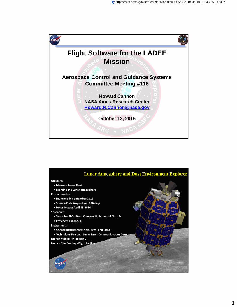
Spacecraft Components - External
LDEX
NMS
UVS
LLCDOptical Module
MG Antenna
Star Tracker Cameras
RCS
OCS(Main Thruster)
Omni Antenna
CSS Mounted on Solar Panels
Spacecraft Components - Internal
UVS
LDEX
Star TrackerCameras
MG Antenna
Omni Antenna
Payload Module
RWA x4
Top of
Radiator
SEPIA
Transponder
Battery
Star Tracker DPU
IAU
IMU
Bottom of
Radiator
VDU
Propulsion
Module
LLST
NMS
3
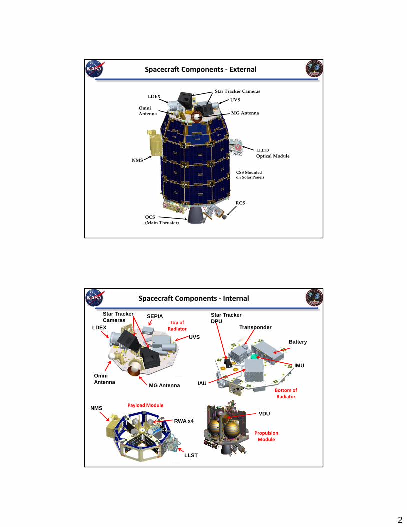
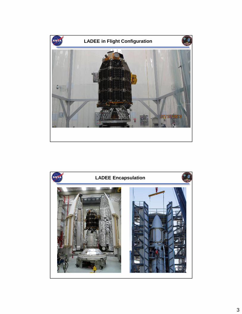
LADEE in Flight Configuration
LADEE Encapsulation
4
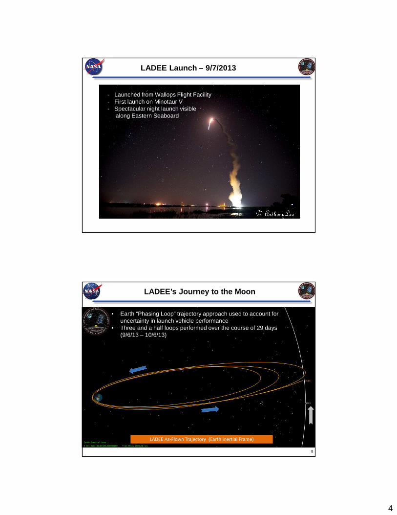
LADEE Launch – 9/7/2013
- Launched from Wallops Flight Facility - First launch on Minotaur V- Spectacular night launch visible
along Eastern Seaboard
LADEE’s Journey to the Moon
LADEE As-Flown Trajectory (Earth Inertial Frame)
8
• Earth “Phasing Loop” trajectory approach used to account for uncertainty in launch vehicle performance
• Three and a half loops performed over the course of 29 days (9/6/13 – 10/6/13)
5
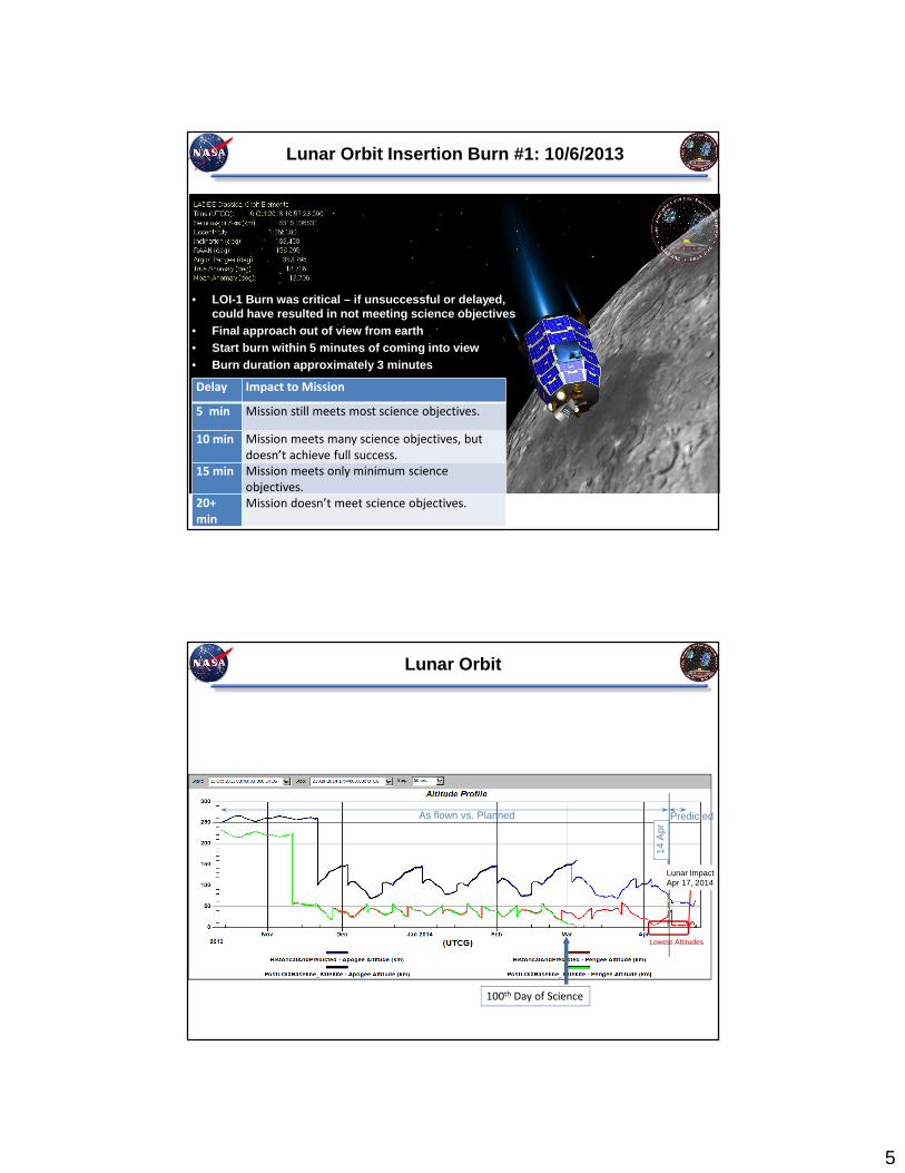
Lunar Orbit Insertion Burn #1: 10/6/2013
• LOI-1 Burn was critical – if unsuccessful or delayed , could have resulted in not meeting science objectiv es
• Final approach out of view from earth• Start burn within 5 minutes of coming into view• Burn duration approximately 3 minutes
9
Delay Impact to Mission
5 min Mission still meets most science objectives.
10 min Mission meets many science objectives, but
doesn’t achieve full success.
15 min Mission meets only minimum science
objectives.
20+
min
Mission doesn’t meet science objectives.
Lunar Orbit
As flown vs. Planned
14 A
pr
Predicted
Eclipse
100th Day of Science
Lowest Altitudes
Lunar ImpactApr 17, 2014Lunar ImpactApr 17, 2014
6
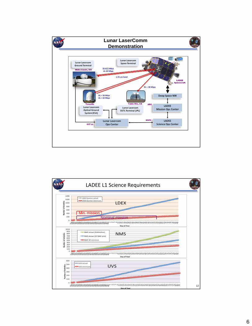
Lunar LaserCommDemonstration
LADEE L1 Science Requirements
Min. missionNominal mission
12
7
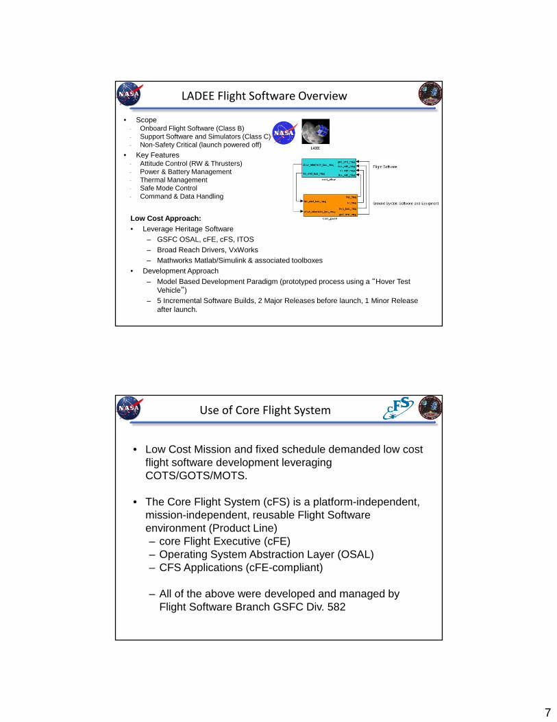
LADEE Flight Software Overview
Low Cost Approach:• Leverage Heritage Software
– GSFC OSAL, cFE, cFS, ITOS– Broad Reach Drivers, VxWorks– Mathworks Matlab/Simulink & associated toolboxes
• Development Approach
– Model Based Development Paradigm (prototyped process using a “Hover Test Vehicle”)
– 5 Incremental Software Builds, 2 Major Releases before launch, 1 Minor Release after launch.
• Scope- Onboard Flight Software (Class B)- Support Software and Simulators (Class C)- Non-Safety Critical (launch powered off)
• Key Features- Attitude Control (RW & Thrusters)- Power & Battery Management- Thermal Management- Safe Mode Control- Command & Data Handling
Use of Core Flight System
• Low Cost Mission and fixed schedule demanded low cost flight software development leveraging COTS/GOTS/MOTS.
• The Core Flight System (cFS) is a platform-independent, mission-independent, reusable Flight Software environment (Product Line)– core Flight Executive (cFE)– Operating System Abstraction Layer (OSAL)– CFS Applications (cFE-compliant)
– All of the above were developed and managed by Flight Software Branch GSFC Div. 582

8
cFS Key Features
• Layered architecture– Reusable components
– Platform Independent
– Supports advances in technology without changes to the framework
cFS Core Services
Executive Services
– Manages the software system
Software Bus Services
– Provides publish/subscribe software bus messaging interface
Time Services
– Provides spacecraft time
Event Services
– Provides interface for sending, filtering, and logging event messages
Table Services
– Provides interface to manage table images
The cFS core layer is the system glue. It provides the common software functions that
are needed by all missions.
9
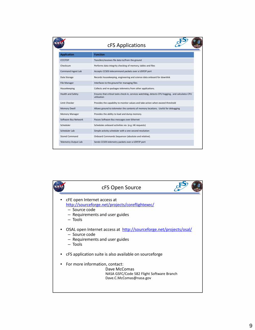
cFS Applications
Application Function
CF/CFDP Transfers/receives file data to/from the ground
Checksum Performs data integrity checking of memory, tables and files
Command Ingest Lab Accepts CCSDS telecommand packets over a UDP/IP port
Data Storage Records housekeeping, engineering and science data onboard for downlink
File Manager Interfaces to the ground for managing files
Housekeeping Collects and re-packages telemetry from other applications.
Health and Safety Ensures that critical tasks check-in, services watchdog, detects CPU hogging, and calculates CPU
utilization
Limit Checker Provides the capability to monitor values and take action when exceed threshold
Memory Dwell Allows ground to telemeter the contents of memory locations. Useful for debugging
Memory Manager Provides the ability to load and dump memory.
Software Bus Network Passes Software Bus messages over Ethernet
Scheduler Schedules onboard activities via (e.g. HK requests)
Scheduler Lab Simple activity scheduler with a one second resolution
Stored Command Onboard Commands Sequencer (absolute and relative).
Telemetry Output Lab Sends CCSDS telemetry packets over a UDP/IP port
cFS Open Source
• cFE open Internet access at http://sourceforge.net/projects/coreflightexec/– Source code– Requirements and user guides– Tools
• OSAL open Internet access at http://sourceforge.net/projects/osal/– Source code– Requirements and user guides– Tools
• cFS application suite is also available on sourceforge
• For more information, contact: Dave McComasNASA GSFC/Code 582 Flight Software [email protected]

10
LADEE FSW Architecture
Cmd & Mode
Processor
ActuatorManager
StateEstimator
Safe ModeController
AttitudeControlSystem
ThermalControlSystem
PowerControlSystem
SchedulerLimit
CheckerStored
CommandsMemoryScrub
MemoryManager
MemoryDwell
HardwareI/O
Health &Safety
DataStorage
FileManager
TelemetryOutput
CCSDS FileDelivery
ChecksumCommand
Ingest
House-keeping
Software Bus
TelemetryGnd Cmds
Sensor Data
Hdwr Cmds
OFSW
System Support and O/S Services
BatteryChargeSystem
FSW Internal
FSW ExternalSimulink
TaskcFSTask
HandWrittenTask
KEY
GSFC OSAL, cFE, cFS, ITOS (GOTS)Broad Reach Drivers (MOTS)Simulink/Matlab, VxWorks (COTS)
Page 20
Simulink Application Summary
Application Function
Command & Mode Processor (CMP)
Decodes and latches commands for other Simulink modules, and handles mode transitions.
Actuator Manager (ACT) Manages which module talks to the thruster & reaction wheel hardware.
State Estimator (EST) Estimates the attitude and rates of the spacecraft.
Safe Mode Control (SMC) Controls the spacecraft orientation and rates while in Safe Mode and Rate Reduction Modes.
Attitude Control System (ACS)
Controls the spacecraft orientation and rates while in DeltaV, FinePoint, or DeltaHModes.
Thermal Control System (TCS)
Turns heaters on and off based on set points.
Power Control System (PCS)
Turns electrical switches on and off as commanded. Provides current limit protection and load shedding.
Battery Charge System (BCS)
Monitors and Controls battery voltage.

11
Model Based Development
• Issues:– Low Cost Mission and fixed schedule demanded rapid, low cost flight software
development process
– Simulations needed for FSW Verification and Mission Operations development, training, and command verification.
• Solution:– Use model based development approach
• Automatic conversion of Models to FSW allows development and testing of algorithms which then becomes Software. Avoids “throwing it over the fence to be coded”.
– Developed multiple simulators of varying degrees of fidelity (WSIM, PIL, HIL)
– Developed Simulink Interface Layer• Allows immediate translation from models to Code allowing rapid turnaround
– Developed an automated test harness for rapid turnaround of verification results
• Result:– Model Based Development coupled with “push button” code generation and
testing was highly effective for rapid software development.
– Models and Simulations used extensively in Mission Operations. • WSIM provided faster than real time capability for rapid command verification.
• Processor in the Loop and Hardware in the Loop simulations provided high fidelity simulations for critical maneuver verification, Ops training, and debugging anomalies
• Fully Coupled Simulations (Power, Thermal, Propulsion, Attitude Control) provided better insight for coupled problems.
Iterative Development
• Develop Models of FSW, Vehicle, and Environment • Automatically generate High-Level Control Software• Integrate with hand-written and heritage software.• Iterate while increasing fidelity of tests – Workstation Sim (WSIM), Processor-In-The-Loop (PIL),
Hardware-in-the-Loop (HIL)• Automated self-documenting tests providing traceability to requirements
Requirements
Design/Algorithm Development
Flight SoftwareModeling
Vehicle &Environment
Modeling
HeritageSoftware
WorkstationSimulations
(eg. Simulink)
Code Generation
IntegratedTests
Processor-in-the-LoopHardware-in-the-Loop
Verification
Heritage Models
Iterate Early and Often
UnitTests
Automated Reporting
Analysis
HandDeveloped
Apps
12
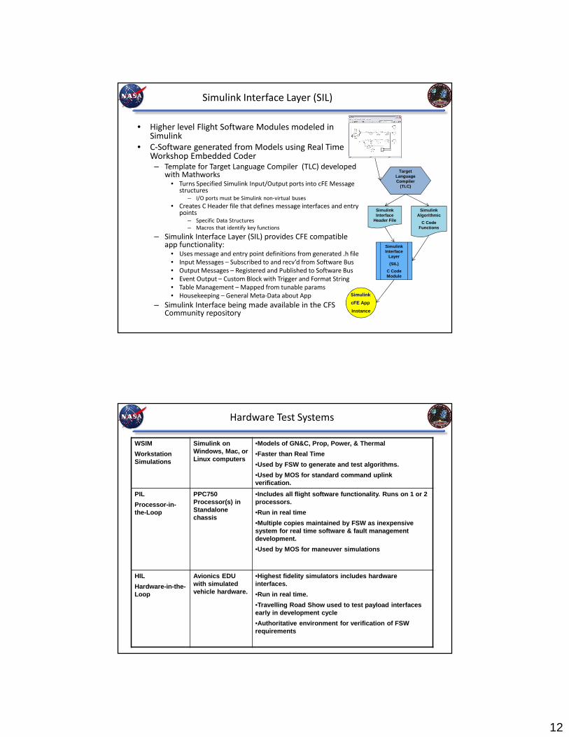
Simulink Interface Layer (SIL)
• Higher level Flight Software Modules modeled in Simulink
• C-Software generated from Models using Real Time Workshop Embedded Coder– Template for Target Language Compiler (TLC) developed
with Mathworks• Turns Specified Simulink Input/Output ports into cFE Message
structures– I/O ports must be Simulink non-virtual buses
• Creates C Header file that defines message interfaces and entry points
– Specific Data Structures
– Macros that identify key functions
– Simulink Interface Layer (SIL) provides CFE compatible app functionality:
• Uses message and entry point definitions from generated .h file
• Input Messages – Subscribed to and recv’d from Software Bus
• Output Messages – Registered and Published to Software Bus
• Event Output – Custom Block with Trigger and Format String
• Table Management – Mapped from tunable params
• Housekeeping – General Meta-Data about App
– Simulink Interface being made available in the CFS Community repository
Simulink Interface
Layer
(SIL)
C Code Module
Target Language Compiler
(TLC)
Simulink Interface
Header File
Simulink Algorithmic
C Code Functions
Simulink
cFE App
Instance
Hardware Test Systems
WSIM
Workstation Simulations
Simulink on Windows, Mac, or Linux computers
•Models of GN&C, Prop, Power, & Thermal
•Faster than Real Time
•Used by FSW to generate and test algorithms.
•Used by MOS for standard command uplink verification.
PIL
Processor-in-the-Loop
PPC750 Processor(s) in Standalone chassis
•Includes all flight software functionality. Runs on 1 or 2 processors.
•Run in real time
•Multiple copies maintained by FSW as inexpensive system for real time software & fault management development.
•Used by MOS for maneuver simulations
HIL
Hardware-in-the-Loop
Avionics EDU with simulated vehicle hardware.
•Highest fidelity simulators includes hardware interfaces.
•Run in real time.
•Travelling Road Show used to test payload interface s early in development cycle
•Authoritative environment for verification of FSW requirements

13
Automated Testing
• Need to verify the integrated flight software, not just the models.
– 144 top level requirements to assess
• Test as we fly!
– Telemetry is the normal indicator of the software health during flight so verify
L4 requirements on the telemetry stream using same tool-chain as in flight.
– Scenarios developed exercising each flight phase. Software response to
identified fault conditions tested in Fault Management scenarios.
– Assertions applied to telemetry stream and software artifacts to verify level 4s.
• Regression test cycle within one week.
– Scenarios themselves take a “long weekend” to compute (in real time).
– Reduction of 70 Gb of scenario data takes an additional day.
– Automated test report for analysis
Automated Test Report
14
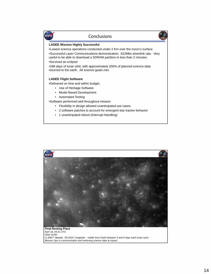
Conclusions
LADEE Mission Highly Successful•Lowest science operations conducted under 2 Km over the moon’s surface•Successful Laser Communications demonstration: 622Mbs downlink rate. Very useful to be able to download a SDRAM partition in less than 2 minutes.•Survived an eclipse!•188 days of lunar orbit, with approximately 200% of planned science data returned to the earth. All science goals met.
LADEE Flight Software •Delivered on time and within budget.
• Use of Heritage Software• Model Based Development• Automated Testing
•Software performed well throughout mission• Flexibility in design allowed unanticipated use cases • 2 software patches to account for emergent star tracker behavior• 1 unanticipated reboot (Interrupt Handling)
Final Resting PlaceApril 18, 04:31 UTCOrbit #229211.8407o latitude, -93.2521o longitude – visible from Earth between 5 and 9 days each lunar cycleMission Ops in communication and retrieving science data at impact