Embed Size (px)
Citation preview
Bracing the Last Line of Defense Against Midair Collisions
Flight SafetyD I G E S T
MARCH 2004
Flight Safety FoundationFor Everyone Concerned With the Safety of Flight
www.fl ightsafety.org
OFFICERS AND STAFF
Chairman, Board of Governors Hon. Carl W. Vogt
President and CEO Stuart Matthews
Executive Vice President Robert H. Vandel
Treasurer James S. Waugh Jr.
ADMINISTRATIVE
Special Events and Products Manager Ellen Plaugher
Manager, Support Services Linda Crowley Horger
FINANCIAL
Director of Finance and Administration Crystal N. Phillips
Accountant Millicent Wheeler
MEMBERSHIP
Director, Membership and Development Ann Hill
Membership Services Coordinator Ahlam Wahdan
PUBLICATIONS
Director of Publications Roger Rozelle
Senior Editor Mark Lacagnina
Senior Editor Wayne Rosenkrans
Senior Editor Linda Werfelman
Associate Editor Rick Darby
Web and Print Production Coordinator Karen K. Ehrlich
Production Designer Ann L. Mullikin
Production Specialist Susan D. Reed
Librarian, Jerry Lederer Aviation Safety Library Patricia Setze
TECHNICAL
Director of Technical Programs James M. Burin
Technical Programs Specialist Joanne Anderson
Managing Director of Internal Evaluation Programs Louis A. Sorrentino III
Q-Star Program Administrator Robert Feeler
Manager, Data Systems and Analysis Robert Dodd, Ph.D.
Manager of Aviation Safety Audits Darol V. Holsman
Founder Jerome Lederer 1902–2004
Flight Safety DigestVol. 23 No. 3 March 2004
In This Issue
Flight Safety Foundation is an international membership organization dedicated to the continuous improvement of aviation safety. Nonprofi t and independent, the Foundation was launched offi cially in 1947 in response to the aviation industry’s need for a neutral clearinghouse to disseminate objective safety information, and for a credible and knowl-edgeable body that would identify threats to safety, analyze the problems and recommend practical solutions to them. Since its beginning, the Foundation has acted in the public interest to produce positive infl uence on aviation safety. Today, the Foundation provides leadership to more than 910 member organizations in more than 142 countries.
Bracing the Last Line of DefenseAgainst Midair Collisions
Recent accidents have prompted the International Civil Aviation Organization to clarify that pilots must comply immediately with airborne collision avoidance system resolution advisories, even when contradictory instructions are issued by air traffi c control.
ACAS Provides an Effective Safety Net When Procedures Are Followed
Airborne collision avoidance system performance monitoring in Europe shows that the signifi cant safety benefi t of ACAS can be diminished by improper procedures, such as failures to comply with resolution advisories.
Australian High-capacity Aircraft Sector Reduces Accident Rate in 2002
The preliminary 2002 data showed a rate of 0.3 accidents per 100,000 departures, the lowest of the non-zero rates reported since 1993. No fatal accidents occurred in this sector during the 1992–2001 period.
Report Cites Turbulence, Convection Factors as Prominent in FARs Part 121 Weather-related Accidents
Weather-related-accident reduction in FARs Part 91 operations appears to be on target for meeting 10-year program goals.
Error in Airspeed CalculationsCited in B-747 Tail Strike
The accident report by the New Zealand Transport Accident Investigation Commission said that the airplane’s rotation speed had been calculated using an aircraft weight that was 100 metric tons (220,460 pounds) less than the actual takeoff weight.
Cover photo: © Copyright 2004 Getty Images Inc.
35LI
BRARY
STATS
29
BR
IEFS
39
151
1FLIGHT SAFETY FOUNDATION • FLIGHT SAFETY DIGEST • MARCH 2004
B R A C I N G T H E L A S T L I N E O F D E F E N S E
Bracing the Last Line of DefenseAgainst Midair CollisionsRecent accidents have prompted the International Civil Aviation Organization to clarify
that pilots must comply immediately with airborne collision avoidance system resolution
advisories, even when contradictory instructions are issued by air traffic control.
— FSF EDITORIAL STAFF
The International Civil Aviation Or-ganization (ICAO) in November 2003 amended its air-navigation procedures to require fl ight crews to
respond immediately to — and in compliance with — resolution advisories (RAs) generated by airborne collision avoidance system (ACAS) equipment.
The new procedures require fl ight crews to comply with RAs even when instructions that contradict
the advisories are received from air traffi c control (ATC).
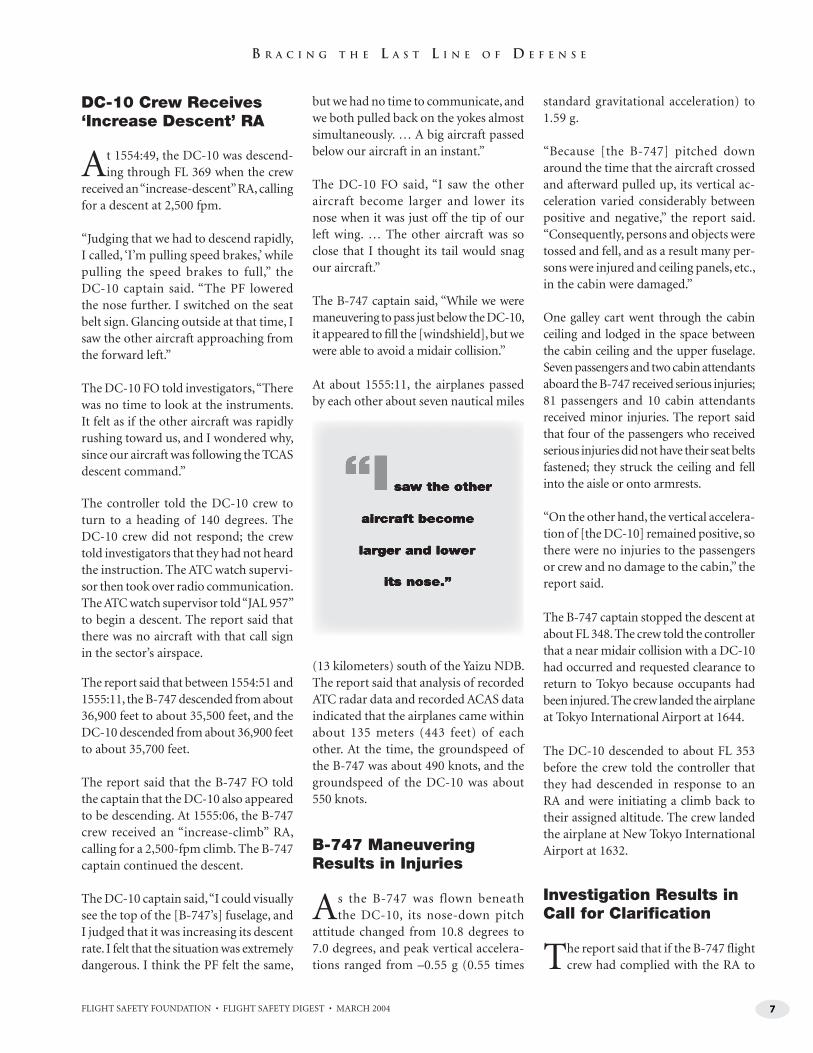
ACAS, also called the traffic-alert and collision avoidance system (TCAS II), uses information received from transponders in other aircraft to calculate the relative motion of the aircraft. When ACAS detects that another aircraft is converging, a traffic advisory (TA) is issued. If the other aircraft continues to converge, an RA is issued. An RA typically consists of aural
+07
–02
+12
1
.5
.5
2
4
6
4
0
1 2
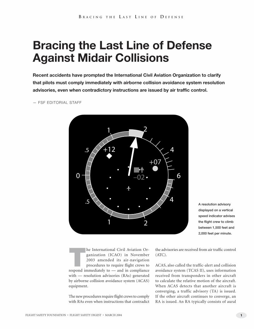
A resolution advisory
displayed on a vertical
speed indicator advises
the flight crew to climb
between 1,500 feet and
2,000 feet per minute.
2 FLIGHT SAFETY FOUNDATION • FLIGHT SAFETY DIGEST • MARCH 2004
B R A C I N G T H E L A S T L I N E O F D E F E N S E
instructions and visual instructions to climb, descend or adjust vertical speed.
Only stall warnings, wind shear warnings and ground-proximity warning system (GPWS) warnings have precedence over ACAS RAs, ICAO said.1
ICAO’s review and amendment of the procedures related to ACAS operation were spurred by the midair collision between a Boeing 757-200 and a Tupolev Tu-154M in Germany in 2002 and the near midair collision between a B-747-400D and a Douglas DC-10-40 in Japan in 2001.
“Factors common to both accidents were that [ATC] had issued instructions which confl icted with an [RA] and fl ight crews had maneuvered their aircraft in the opposite sense [e.g., conducted a descent, rather than a climb] to the RAs that had been issued,” ICAO said.2
B-757, Tu-154 Paths Crossed Over Intersection
The investigation of the midair collision over Germany, which occurred July 1, 2002, was
ongoing as of March 20, 2004. The following information is from an August 2002 status report on the accident investigation by the German Bundesstelle fur Flugunfalluntersuchung (Federal Bureau of Aircraft Accidents Investigation [BFU])3 and from Airclaims.4
The B-757, with two pilots aboard, was being operated by DHL International on a scheduled cargo fl ight from Bergamo, Italy, to Brussels, Belgium. The fl ight had origi-nated in Bahrain.
The Tu-154 was being oper-ated by Bashkirian Airlines as a charter fl ight from Moscow, Russia, to Barcelona, Spain, with 12 crewmembers and 57 passengers aboard.
Both airplanes were being fl own on area navigation routes that intersected near Uberlingen, Germany, which is on the
northern shore of Lake Constance. The intersec-tion was in an ATC sector in German airspace that was controlled by a Swiss ATC facility. The B-757 was approaching the intersection from the south. The Tu-154 was approaching the intersection from the east.
The B-757 was being fl own at Flight Level (FL) 260 (approximately 26,000 feet) when the fl ight crew established radio communication with Zurich Area Control Center (ACC) at 2320 local time. The controller told the crew to climb to FL 320. The crew requested clearance to climb to FL 360, and the controller told the crew to climb to FL 360. The B-757 reached FL 360 at 2329.
The Tu-154 was being fl own at FL 360 when the fl ight crew established radio communication with Zurich ACC at 2330. The crews of both airplanes communicated with Zurich ACC on the same radio frequency.
Both airplanes were carrying the same type of ACAS equipment (TCAS II equipment with the latest software version [Version 7]).
“Both operators had provided training programs for TCAS, and the crews had completed the cor-responding training,” BFU said.
At 2334:42, the ACAS equipment in both airplanes issued TAs. Seven seconds later, the controller told the Tu-154 crew to “expedite descent to FL 350.”
“The crew did not confi rm this instruction but initiated a descent,” BFU said. “Simultaneously, the airborne TCAS issued the command [an RA] to climb. Another seven seconds later, the radar controller repeated his instruction to the [Tu-154] crew to conduct an expedited descent to FL 350. This instruction was immediately acknowledged by the crew.”
B-757 Crew Followed RA
The ACAS equipment in the B-757 issued an RA to conduct a descent about the same
time the controller repeated his instruction to the Tu-154 crew to descend.
“[The B-757 crew] immediately followed this command and, after a further 14 seconds, received
3FLIGHT SAFETY FOUNDATION • FLIGHT SAFETY DIGEST • MARCH 2004
B R A C I N G T H E L A S T L I N E O F D E F E N S E
the command to increase the [rate of] descent,” BFU said. “The crew told the controller that they were complying with a TCAS RA at 2335:19.”
Five seconds after the B-757 crew received the “in-crease descent” RA, the Tu-154 crew received an “increase climb” RA. Nevertheless, the Tu-154 crew continued the descent. About 17 seconds later, at 2135:32, the airplanes collided at about FL 350.
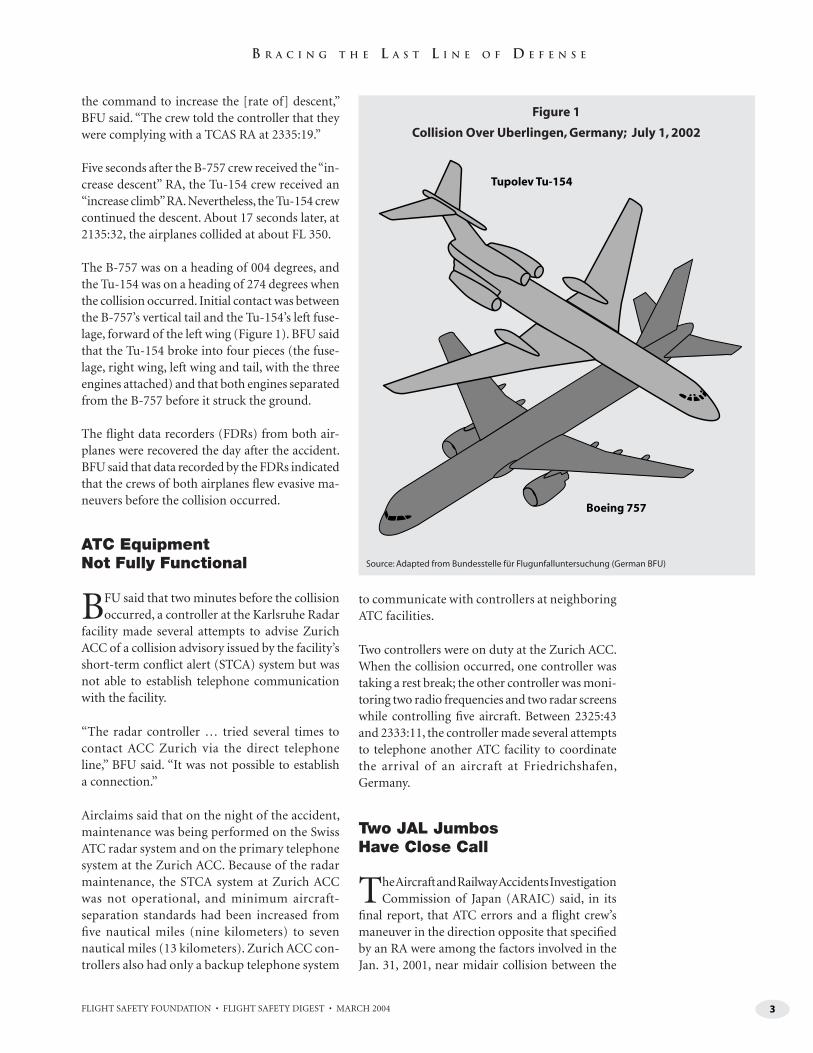
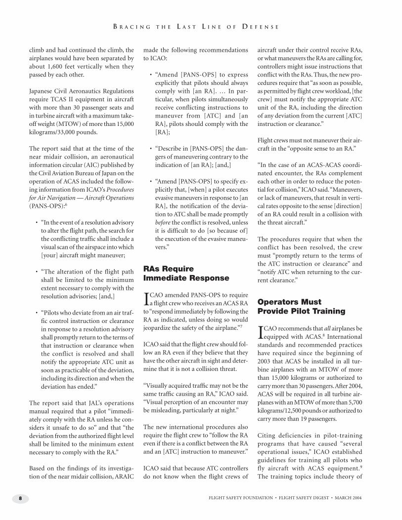
The B-757 was on a heading of 004 degrees, and the Tu-154 was on a heading of 274 degrees when the collision occurred. Initial contact was between the B-757’s vertical tail and the Tu-154’s left fuse-lage, forward of the left wing (Figure 1). BFU said that the Tu-154 broke into four pieces (the fuse-lage, right wing, left wing and tail, with the three engines attached) and that both engines separated from the B-757 before it struck the ground.
The fl ight data recorders (FDRs) from both air-planes were recovered the day after the accident. BFU said that data recorded by the FDRs indicated that the crews of both airplanes fl ew evasive ma-neuvers before the collision occurred.
ATC Equipment Not Fully Functional
BFU said that two minutes before the collision occurred, a controller at the Karlsruhe Radar
facility made several attempts to advise Zurich ACC of a collision advisory issued by the facility’s short-term confl ict alert (STCA) system but was not able to establish telephone communication with the facility.
“The radar controller … tried several times to contact ACC Zurich via the direct telephone line,” BFU said. “It was not possible to establish a connection.”
Airclaims said that on the night of the accident, maintenance was being performed on the Swiss ATC radar system and on the primary telephone system at the Zurich ACC. Because of the radar maintenance, the STCA system at Zurich ACC was not operational, and minimum aircraft-separation standards had been increased from fi ve nautical miles (nine kilometers) to seven nautical miles (13 kilometers). Zurich ACC con-trollers also had only a backup telephone system
to communicate with controllers at neighboring ATC facilities.
Two controllers were on duty at the Zurich ACC. When the collision occurred, one controller was taking a rest break; the other controller was moni-toring two radio frequencies and two radar screens while controlling fi ve aircraft. Between 2325:43 and 2333:11, the controller made several attempts to telephone another ATC facility to coordinate the arrival of an aircraft at Friedrichshafen, Germany.
Two JAL Jumbos Have Close Call
The Aircraft and Railway Accidents Investigation Commission of Japan (ARAIC) said, in its
fi nal report, that ATC errors and a fl ight crew’s maneuver in the direction opposite that specifi ed by an RA were among the factors involved in the Jan. 31, 2001, near midair collision between the
Tupolev Tu-154
Boeing 757
Figure 1
Collision Over Uberlingen, Germany; July 1, 2002
Source: Adapted from Bundesstelle für Flugunfalluntersuchung (German BFU)
4 FLIGHT SAFETY FOUNDATION • FLIGHT SAFETY DIGEST • MARCH 2004
B R A C I N G T H E L A S T L I N E O F D E F E N S E
B-747 and the DC-10 over the Pacifi c Ocean, south of Yaizu, Japan.5
Both airplanes were being operated by Japan Airlines (JAL). The B-747, Flight 907, was climbing to cruise altitude after departing from Tokyo for a scheduled two-hour, 22-minute fl ight to Naha, Okinawa Islands (Figure 2). Aboard the airplane were 411 passengers and 16 crewmembers.
Four pilots were on the B-747’s fl ight deck. The captain was in the left front seat. The captain, 40, had 7,446 fl ight hours, including 3,758 fl ight hours in type. The fi rst offi cer (FO) was in the left observer’s seat (jump seat), behind the captain. The FO, 28, had 569 fl ight hours, including 288 fl ight hours in type. In the right front seat was a 26-year-old pilot with 303 fl ight hours who was being trained to upgrade to fi rst offi cer; the report
referred to him as the “FO-trainee.” Another pilot receiving FO-upgrade training was in the right observer’s seat.
The DC-10, Flight 958, was in cruise fl ight at FL 370 during a scheduled fl ight with 237 passengers and 13 crewmembers to Tokyo from Pusan, South Korea.
The DC-10 fl ight crew comprised three pilots. The captain, 45, had 6,584 fl ight hours, including 5,689 fl ight hours in type; he was in the right front seat. The FO, 49, had 4,333 fl ight hours, including 3,873 fl ight hours in type. The FO, who was being trained to upgrade to captain, was in the left front seat. The fl ight engineer, 43, had 8,336 fl ight hours, all in DC-10s.
The Tokyo ACC sector in which the airplanes were being fl own — the Kanto South C sector — was
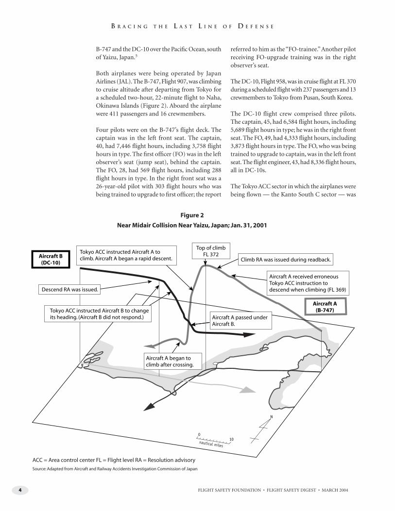
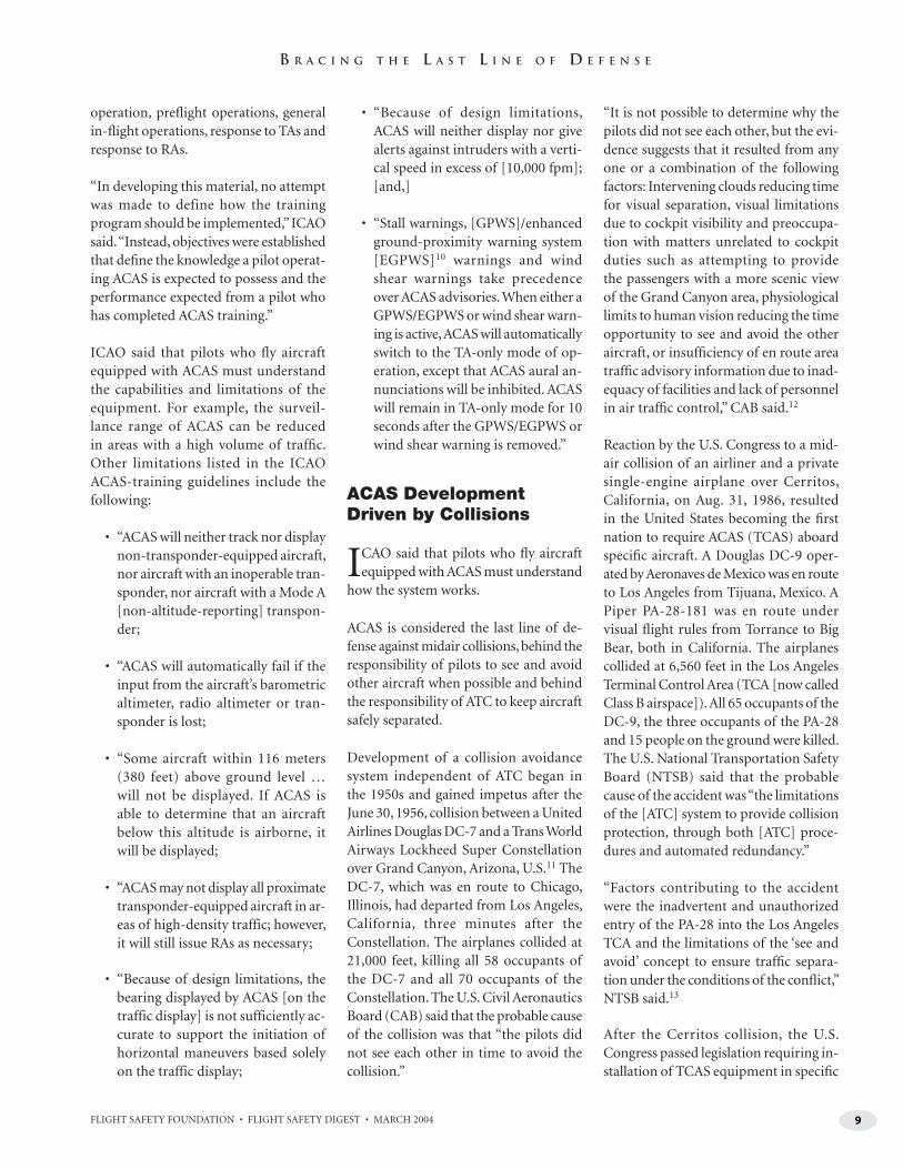
Climb RA was issued during readback.
Aircraft A(B-747)
Aircraft A passed underAircraft B.
Top of climbFL 372
Descend RA was issued.
Aircraft A received erroneousTokyo ACC instruction todescend when climbing (FL 369)
Tokyo ACC instructed Aircraft A toclimb. Aircraft A began a rapid descent.Aircraft B
(DC-10)
Tokyo ACC instructed Aircraft B to changeits heading. (Aircraft B did not respond.)
Aircraft A began toclimb after crossing.
Figure 2
Near Midair Collision Near Yaizu, Japan; Jan. 31, 2001
ACC = Area control center FL = Flight level RA = Resolution advisory
Source: Adapted from Aircraft and Railway Accidents Investigation Commission of Japan
5FLIGHT SAFETY FOUNDATION • FLIGHT SAFETY DIGEST • MARCH 2004
B R A C I N G T H E L A S T L I N E O F D E F E N S E
being controlled by three controllers. The radar console was manned by a controller receiving familiarization training for the sector. Also on duty were an ATC watch supervisor and an ATC coordinator.
At 1541 local time, the B-747 crew told Tokyo ACC that they were fl ying the airplane through 11,000 feet in a climb to FL 390. The controller told the crew to fl y directly to the Yaizu nondirectional bea-con (NDB) and to climb to FL 350. The report said that the altitude restriction was required because another airplane, American Airlines Flight 157, was in cruise fl ight, southwestbound, at FL 390.
The B-747 captain told investigators that at this time, he observed a contrail at a relative bearing of 11 o’clock.
“It was at a higher altitude and approximately 40 nautical miles [74 kilometers] from our position,” the captain said. “I talked with the trainee pilot about how close the traffi c would come before being displayed [as a TCAS symbol] on the navigation dis-play. The traffi c was displayed … when it reached 25 nautical miles [46 kilometers]. The TCAS-indicated altitude was FL 370. The cockpit crew discussed that we should keep an eye on the traffi c.”
Traffi c Was ‘About theLevel I Could Handle’
The report said that between 1543 and 1552, the controller handled 14 aircraft and made
37 radio transmissions under the guidance of the ATC watch supervisor.
The controller told investigators, “The traffi c vol-ume at the time of the on-the-job training was at about the level I could handle.”
The B-747 was east of the Yaizu NDB and was be-ing fl own through about 21,600 feet at 1546, when the controller told the crew to climb to FL 390.
At 1547, the controller told the crew of Flight 157 to descend to FL 350. The controller repeated the instruction, but there was no response from Flight 157. The report said that the crew of Flight 157 had not yet been instructed by their current sector controller to establish radio communication with the Kanto South C sector.
At 1548:14, the DC-10 flight crew established radio commu-nication with the Kanto South C sector and said that they were at FL 370. At the time, the DC-10 was west of the Yaizu NDB.
The crew of Flight 157 estab-lished radio communication with the Kanto South C sector at 1548:37 and told the control-ler that they were at FL 390. The controller told the crew to descend to FL 350. The crew ac-knowledged the instruction and said that they were beginning the descent.
The report said that between 1552 and 1554:22, the controller made four radio transmissions to three aircraft.
Near the Yaizu NDB at 1553:50, the B-747 crew began a climbing left turn, from a heading of 270 degrees to a heading of 207 degrees.
The DC-10 was on a heading of 095 degrees, and its groundspeed was 567 knots, when the FO told the captain that he saw traffi c at their 10 o’clock to 11 o’clock position. The report said that at 1554:00, the DC-10’s ACAS display showed a symbol cor-responding to the B-747 with an arrow indicating that the B-747 was climbing.
“The traffi c was displayed on the TCAS screen beyond the 10-nautical-mile [19-kilometer] arc at between 12 [nautical miles] and 13 nautical miles [22 kilometers and 24 kilometers],” the DC-10 captain said. “As we saw the other aircraft turning over Yaizu, a TCAS ‘traffi c, traffi c’ TA sounded while we were about 10 nautical miles distant at FL 370. The other aircraft’s altitude was also displayed as FL 370. The PF [pilot fl ying (the FO)] disengaged the autothrottles in anticipation of an RA.”
Controllers Receive Confl ict Alert
The ATC watch supervisor was providing comments to the controller about the tasks
he had performed and was discussing the traffi c
6 FLIGHT SAFETY FOUNDATION • FLIGHT SAFETY DIGEST • MARCH 2004
B R A C I N G T H E L A S T L I N E O F D E F E N S E
situation with the controller at 1554:18, when a confl ict alert was displayed on the controller’s radar screen.
“I don’t recall at what time I received the hand-off of [the DC-10] from the adja-cent sector,” the controller said. “I fi rst became aware of [the DC-10’s] presence when the confl ict alert operated and the letters ‘CNF’ fl ashed in the data blocks of [the B-747 and the DC-10].”
The ATC watch supervisor said, “I was in a fl urry because I had forgotten about the presence of [the DC-10]. At that time, I deemed that the best decision was to [issue an instruction to the DC-10 crew to] descend.”
The controller, however, told the B-747 crew to descend to FL 350.
The B-747 crew used their call sign when they acknowledged the instruction. The crew also told the controller, “Traffi c in sight.”
Nevertheless, the ATC watch supervisor said that she was “convinced” at the time that the controller had issued the descent instruction to the DC-10 crew.
The report said, “Although [the B-747 crew] read back the instruction and stated their fl ight number, neither the ATC trainee nor the ATC watch supervi-sor noticed that the fl ight number in the readback was that of [the B-747], not that of the intended aircraft [the DC-10].”
The B-747 captain said, “Since we had been instructed to descend during a climb, I disengaged the autopilot and autothrottles, and reduced the power to idle while commencing the descent. Our aircraft ascended to around FL 371 due to inertia [before beginning to descend].”
Both Crews Receive RAs
At 1554:34, the DC-10 crew received an RA calling for a descent at 1,500
feet per minute (fpm). One second later, the B-747 crew received an RA calling for a climb at 1,500 fpm.
The DC-10 captain said, “The PF dis-engaged the autopilot, set power to idle and lowered the nose little by little. Since the descent rate at this time was less than 1,000 feet per minute, I exerted forward pressure on the control wheel while ad-vising, ‘Lower it further.’”
The B-747 captain said that his airplane had begun to descend when the climb RA was issued and that he decided to continue the descent.
“At that time, I observed the other aircraft approaching from the forward right at
about the same altitude, but I had already initiated a descent and, judging that the best way to avoid a collision at that altitude would be to continue descend-ing contrary to the TCAS command, I continued descending to FL 350,” the captain said. “Further, I also considered the risk of stalling if we pitched up, given the insuffi cient thrust, leading to an even more dangerous situation.”
The B-747 FO (who was in the observer’s seat) told investigators that the captain announced to the crew that because the airplane had already been placed in a descent, they would continue the de-scent. The FO said that he believed the captain’s actions were timely and without irregularity.
“At that time, following the TCAS RA, reapplying maximum power and pitching up to comply with the RA command, at an altitude of what I thought was around 37,000 feet, would have been extremely dangerous,” the FO said.
Investigators calculated that under the existing conditions, the B-747’s stall speed was 215 knots. The airplane was descending at about 280 knots.
“Therefore, it is considered that [the B-747] had a small margin of speed over the above-mentioned stall speed,” the report said. “It is estimated that [the airplane] would have been able to gain altitude to some extent using this airspeed margin for climb by trans-forming kinetic energy into potential energy.”
The B-747 FO-trainee told investigators, “I felt that [the other aircraft] would pass in front of or just above my eyes, and I thought that if we continued as we were, we would collide. The captain applied further pitch-down [control input], at which time I felt as if I were being lifted.”
At 1554:38, the controller, who believed that he had told the DC-10 crew to de-scend, told the DC-10 crew to turn to a heading of 130 degrees for spacing.
“[The DC-10’s] altitude did not change, so the trainee [controller] instructed it to fl y heading 130 degrees,” the ATC watch supervisor said. “Although I thought that the first thing was to provide vertical separation, I did not think it necessary to dare to correct his instruction.”
The DC-10 crew did not acknowledge the instruction; they told investigators that they had not heard the instruction.
“The fl ight crew may have had their at-tention focused on coping with the RA,” the report said.
7FLIGHT SAFETY FOUNDATION • FLIGHT SAFETY DIGEST • MARCH 2004
B R A C I N G T H E L A S T L I N E O F D E F E N S E
DC-10 Crew Receives ‘Increase Descent’ RA
At 1554:49, the DC-10 was descend-ing through FL 369 when the crew
received an “increase-descent” RA, calling for a descent at 2,500 fpm.
“Judging that we had to descend rapidly, I called, ‘I’m pulling speed brakes,’ while pulling the speed brakes to full,” the DC-10 captain said. “The PF lowered the nose further. I switched on the seat belt sign. Glancing outside at that time, I saw the other aircraft approaching from the forward left.”
The DC-10 FO told investigators, “There was no time to look at the instruments. It felt as if the other aircraft was rapidly rushing toward us, and I wondered why, since our aircraft was following the TCAS descent command.”
The controller told the DC-10 crew to turn to a heading of 140 degrees. The DC-10 crew did not respond; the crew told investigators that they had not heard the instruction. The ATC watch supervi-sor then took over radio communication. The ATC watch supervisor told “JAL 957” to begin a descent. The report said that there was no aircraft with that call sign in the sector’s airspace.
The report said that between 1554:51 and 1555:11, the B-747 descended from about 36,900 feet to about 35,500 feet, and the DC-10 descended from about 36,900 feet to about 35,700 feet.
The report said that the B-747 FO told the captain that the DC-10 also appeared to be descending. At 1555:06, the B-747 crew received an “increase-climb” RA, calling for a 2,500-fpm climb. The B-747 captain continued the descent.
The DC-10 captain said, “I could visually see the top of the [B-747’s] fuselage, and I judged that it was increasing its descent rate. I felt that the situation was extremely dangerous. I think the PF felt the same,
but we had no time to communicate, and we both pulled back on the yokes almost simultaneously. … A big aircraft passed below our aircraft in an instant.”
The DC-10 FO said, “I saw the other aircraft become larger and lower its nose when it was just off the tip of our left wing. … The other aircraft was so close that I thought its tail would snag our aircraft.”
The B-747 captain said, “While we were maneuvering to pass just below the DC-10, it appeared to fi ll the [windshield], but we were able to avoid a midair collision.”
At about 1555:11, the airplanes passed by each other about seven nautical miles
(13 kilometers) south of the Yaizu NDB. The report said that analysis of recorded ATC radar data and recorded ACAS data indicated that the airplanes came within about 135 meters (443 feet) of each other. At the time, the groundspeed of the B-747 was about 490 knots, and the groundspeed of the DC-10 was about 550 knots.
B-747 Maneuvering Results in Injuries
As the B-747 was flown beneath the DC-10, its nose-down pitch
attitude changed from 10.8 degrees to 7.0 degrees, and peak vertical accelera-tions ranged from –0.55 g (0.55 times
standard gravitational acceleration) to 1.59 g.
“Because [the B-747] pitched down around the time that the aircraft crossed and afterward pulled up, its vertical ac-celeration varied considerably between positive and negative,” the report said. “Consequently, persons and objects were tossed and fell, and as a result many per-sons were injured and ceiling panels, etc., in the cabin were damaged.”
One galley cart went through the cabin ceiling and lodged in the space between the cabin ceiling and the upper fuselage. Seven passengers and two cabin attendants aboard the B-747 received serious injuries; 81 passengers and 10 cabin attendants received minor injuries. The report said that four of the passengers who received serious injuries did not have their seat belts fastened; they struck the ceiling and fell into the aisle or onto armrests.
“On the other hand, the vertical accelera-tion of [the DC-10] remained positive, so there were no injuries to the passengers or crew and no damage to the cabin,” the report said.
The B-747 captain stopped the descent at about FL 348. The crew told the controller that a near midair collision with a DC-10 had occurred and requested clearance to return to Tokyo because occupants had been injured. The crew landed the airplane at Tokyo International Airport at 1644.
The DC-10 descended to about FL 353 before the crew told the controller that they had descended in response to an RA and were initiating a climb back to their assigned altitude. The crew landed the airplane at New Tokyo International Airport at 1632.
Investigation Results in Call for Clarifi cation
The report said that if the B-747 fl ight crew had complied with the RA to
8 FLIGHT SAFETY FOUNDATION • FLIGHT SAFETY DIGEST • MARCH 2004
B R A C I N G T H E L A S T L I N E O F D E F E N S E
climb and had continued the climb, the airplanes would have been separated by about 1,600 feet vertically when they passed by each other.
Japanese Civil Aeronautics Regulations require TCAS II equipment in aircraft with more than 30 passenger seats and in turbine aircraft with a maximum take-off weight (MTOW) of more than 15,000 kilograms/33,000 pounds.
The report said that at the time of the near midair collision, an aeronautical information circular (AIC) published by the Civil Aviation Bureau of Japan on the operation of ACAS included the follow-ing information from ICAO’s Procedures for Air Navigation — Aircraft Operations (PANS-OPS):6
• “In the event of a resolution advisory to alter the flight path, the search for the conflicting traffic shall include a visual scan of the airspace into which [your] aircraft might maneuver;
• “The alteration of the flight path shall be limited to the minimum extent necessary to comply with the resolution advisories; [and,]
• “Pilots who deviate from an air traf-fic control instruction or clearance in response to a resolution advisory shall promptly return to the terms of that instruction or clearance when the conflict is resolved and shall notify the appropriate ATC unit as soon as practicable of the deviation, including its direction and when the deviation has ended.”
The report said that JAL’s operations manual required that a pilot “immedi-ately comply with the RA unless he con-siders it unsafe to do so” and that “the deviation from the authorized fl ight level shall be limited to the minimum extent necessary to comply with the RA.”
Based on the fi ndings of its investiga-tion of the near midair collision, ARAIC
made the following recommendations to ICAO:
• “Amend [PANS-OPS] to express explicitly that pilots should always comply with [an RA]. … In par-ticular, when pilots simultaneously receive conflicting instructions to maneuver from [ATC] and [an RA], pilots should comply with the [RA];
• “Describe in [PANS-OPS] the dan-gers of maneuvering contrary to the indication of [an RA]; [and,]
• “Amend [PANS-OPS] to specify ex-plicitly that, [when] a pilot executes evasive maneuvers in response to [an RA], the notification of the devia-tion to ATC shall be made promptly before the conflict is resolved, unless it is difficult to do [so because of] the execution of the evasive maneu-vers.”
RAs Require Immediate Response
ICAO amended PANS-OPS to require a fl ight crew who receives an ACAS RA
to “respond immediately by following the RA as indicated, unless doing so would jeopardize the safety of the airplane.”7
ICAO said that the fl ight crew should fol-low an RA even if they believe that they have the other aircraft in sight and deter-mine that it is not a collision threat.
“Visually acquired traffi c may not be the same traffi c causing an RA,” ICAO said. “Visual perception of an encounter may be misleading, particularly at night.”
The new international procedures also require the fl ight crew to “follow the RA even if there is a confl ict between the RA and an [ATC] instruction to maneuver.”
ICAO said that because ATC controllers do not know when the fl ight crews of
aircraft under their control receive RAs, or what maneuvers the RAs are calling for, controllers might issue instructions that confl ict with the RAs. Thus, the new pro-cedures require that “as soon as possible, as permitted by fl ight crew workload, [the crew] must notify the appropriate ATC unit of the RA, including the direction of any deviation from the current [ATC] instruction or clearance.”
Flight crews must not maneuver their air-craft in the “opposite sense to an RA.”
“In the case of an ACAS-ACAS coordi-nated encounter, the RAs complement each other in order to reduce the poten-tial for collision,” ICAO said. “Maneuvers, or lack of maneuvers, that result in verti-cal rates opposite to the sense [direction] of an RA could result in a collision with the threat aircraft.”
The procedures require that when the conflict has been resolved, the crew must “promptly return to the terms of the ATC instruction or clearance” and “notify ATC when returning to the cur-rent clearance.”
Operators Must Provide Pilot Training
ICAO recommends that all airplanes be equipped with ACAS.8 International
standards and recommended practices have required since the beginning of 2003 that ACAS be installed in all tur-bine airplanes with an MTOW of more than 15,000 kilograms or authorized to carry more than 30 passengers. After 2004, ACAS will be required in all turbine air-planes with an MTOW of more than 5,700 kilograms/12,500 pounds or authorized to carry more than 19 passengers.
Citing deficiencies in pilot-training programs that have caused “several operational issues,” ICAO established guidelines for training all pilots who fly aircraft with ACAS equipment.9 The training topics include theory of
9FLIGHT SAFETY FOUNDATION • FLIGHT SAFETY DIGEST • MARCH 2004
B R A C I N G T H E L A S T L I N E O F D E F E N S E
operation, prefl ight operations, general in-fl ight operations, response to TAs and response to RAs.
“In developing this material, no attempt was made to define how the training program should be implemented,” ICAO said. “Instead, objectives were established that defi ne the knowledge a pilot operat-ing ACAS is expected to possess and the performance expected from a pilot who has completed ACAS training.”
ICAO said that pilots who fl y aircraft equipped with ACAS must understand the capabilities and limitations of the equipment. For example, the surveil-lance range of ACAS can be reduced in areas with a high volume of traffi c. Other limitations listed in the ICAO ACAS-training guidelines include the following:
• “ACAS will neither track nor display non-transponder-equipped aircraft, nor aircraft with an inoperable tran-sponder, nor aircraft with a Mode A [non-altitude-reporting] transpon-der;
• “ACAS will automatically fail if the input from the aircraft’s barometric altimeter, radio altimeter or tran-sponder is lost;
• “Some aircraft within 116 meters (380 feet) above ground level … will not be displayed. If ACAS is able to determine that an aircraft below this altitude is airborne, it will be displayed;
• “ACAS may not display all proximate transponder-equipped aircraft in ar-eas of high-density traffic; however, it will still issue RAs as necessary;
• “Because of design limitations, the bearing displayed by ACAS [on the traffic display] is not sufficiently ac-curate to support the initiation of horizontal maneuvers based solely on the traffic display;
• “Because of design limitations, ACAS will neither display nor give alerts against intruders with a verti-cal speed in excess of [10,000 fpm]; [and,]
• “Stall warnings, [GPWS]/enhanced ground-proximity warning system [EGPWS]10 warnings and wind shear warnings take precedence over ACAS advisories. When either a GPWS/EGPWS or wind shear warn-ing is active, ACAS will automatically switch to the TA-only mode of op-eration, except that ACAS aural an-nunciations will be inhibited. ACAS will remain in TA-only mode for 10 seconds after the GPWS/EGPWS or wind shear warning is removed.”
ACAS Development Driven by Collisions
ICAO said that pilots who fl y aircraft equipped with ACAS must understand
how the system works.
ACAS is considered the last line of de-fense against midair collisions, behind the responsibility of pilots to see and avoid other aircraft when possible and behind the responsibility of ATC to keep aircraft safely separated.
Development of a collision avoidance system independent of ATC began in the 1950s and gained impetus after the June 30, 1956, collision between a United Airlines Douglas DC-7 and a Trans World Airways Lockheed Super Constellation over Grand Canyon, Arizona, U.S.11 The DC-7, which was en route to Chicago, Illinois, had departed from Los Angeles, California, three minutes after the Constellation. The airplanes collided at 21,000 feet, killing all 58 occupants of the DC-7 and all 70 occupants of the Constellation. The U.S. Civil Aeronautics Board (CAB) said that the probable cause of the collision was that “the pilots did not see each other in time to avoid the collision.”
“It is not possible to determine why the pilots did not see each other, but the evi-dence suggests that it resulted from any one or a combination of the following factors: Intervening clouds reducing time for visual separation, visual limitations due to cockpit visibility and preoccupa-tion with matters unrelated to cockpit duties such as attempting to provide the passengers with a more scenic view of the Grand Canyon area, physiological limits to human vision reducing the time opportunity to see and avoid the other aircraft, or insuffi ciency of en route area traffi c advisory information due to inad-equacy of facilities and lack of personnel in air traffi c control,” CAB said.12
Reaction by the U.S. Congress to a mid-air collision of an airliner and a private single-engine airplane over Cerritos, California, on Aug. 31, 1986, resulted in the United States becoming the fi rst nation to require ACAS (TCAS) aboard specifi c aircraft. A Douglas DC-9 oper-ated by Aeronaves de Mexico was en route to Los Angeles from Tijuana, Mexico. A Piper PA-28-181 was en route under visual fl ight rules from Torrance to Big Bear, both in California. The airplanes collided at 6,560 feet in the Los Angeles Terminal Control Area (TCA [now called Class B airspace]). All 65 occupants of the DC-9, the three occupants of the PA-28 and 15 people on the ground were killed. The U.S. National Transportation Safety Board (NTSB) said that the probable cause of the accident was “the limitations of the [ATC] system to provide collision protection, through both [ATC] proce-dures and automated redundancy.”
“Factors contributing to the accident were the inadvertent and unauthorized entry of the PA-28 into the Los Angeles TCA and the limitations of the ‘see and avoid’ concept to ensure traffi c separa-tion under the conditions of the confl ict,” NTSB said.13
After the Cerritos collision, the U.S. Congress passed legislation requiring in-stallation of TCAS equipment in specifi c
10 FLIGHT SAFETY FOUNDATION • FLIGHT SAFETY DIGEST • MARCH 2004
B R A C I N G T H E L A S T L I N E O F D E F E N S E
aircraft. The U.S. Federal Aviation Administration (FAA) in 1989 published requirements for installa-tion of TCAS II equipment, on a phased schedule between 1990 and 1993, in large airplanes (with MTOWs more than 12,500 pounds) with more than 30 passenger seats. FAA also required that by the end of 1995, all airplanes with 10 to 30 passenger seats used in air carrier operations be equipped either with TCAS II or TCAS I.14
(TCAS I equipment provides TAs only and was developed primarily for regional airliners and general aviation aircraft.)
In Europe and in the United States, research and development of ACAS/TCAS III equipment,
which would provide RAs that include horizontal collision avoidance maneuvers as well as vertical collision avoidance ma-neuvers, has been terminated, be-cause the automatic dependent surveillance–broadcast (ADS-B) system, which is under develop-ment, has the potential to help provide this capability.
ADS-B involves broadcast of position information at regular time intervals by aircraft on the ground and in the air. The tech-nology is being developed for
several uses, such as the airborne separation as-sistance system (ASAS), which might enable fl ight crews to participate with ATC in traffi c spacing and separation. ICAO said that ADS-B data might be used to improve ACAS collision logic.
How ACAS Works
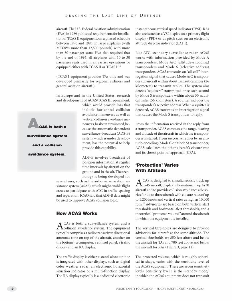
ACAS is both a surveillance system and a collision avoidance system. The equipment
typically comprises a radio transceiver, directional antennas (one on top of the aircraft, another on the bottom), a computer, a control panel, a traffi c display and an RA display.
The traffi c display is either a stand-alone unit or is integrated with other displays, such as digital color weather radar, an electronic horizontal situation indicator or a multi-function display. The RA display typically is a dedicated electronic
instantaneous vertical speed indicator (IVSI). RAs also are issued as a VSI display on a primary fl ight display (PFD) or as pitch cues on an electronic attitude director indicator (EADI).
Like ATC secondary surveillance radar, ACAS works with information provided by Mode A transponders, Mode A/C (altitude-encoding) transponders and Mode S (selective address) transponders. ACAS transmits an “all-call” inter-rogation signal that causes Mode A/C transpon-ders in aircraft within about 14 nautical miles (26 kilometers) to transmit replies. The system also detects “squitters” transmitted once each second by Mode S transponders within about 30 nauti-cal miles (56 kilometers). A squitter includes the transponder’s selective address. When a squitter is detected, ACAS transmits an interrogation signal that causes the Mode S transponder to reply.
From the information received in the reply from a transponder, ACAS computes the range, bearing and altitude of the aircraft in which the transpon-der is installed. From successive replies by an alti-tude-encoding (Mode C or Mode S) transponder, ACAS calculates the other aircraft’s closure rate and its closest point of approach (CPA).
‘Protection’ Varies With Altitude
ACAS is designed to simultaneously track up to 45 aircraft, display information on up to 30
aircraft and to provide collision avoidance adviso-ries for up to three aircraft with closure rates of up to 1,200 knots and vertical rates as high as 10,000 fpm.16 Advisories are based on both vertical alert thresholds and horizontal alert thresholds, and a theoretical “protected volume” around the aircraft in which the equipment is installed.
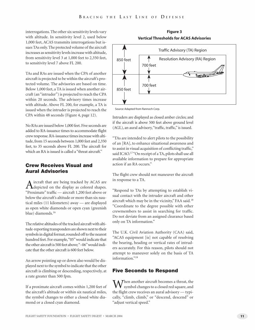
The vertical thresholds are designed to provide advisories for aircraft at the same altitude. The vertical thresholds are 850 feet above and below the aircraft for TAs and 700 feet above and below the aircraft for RAs (Figure 3, page 11).
The protected volume, which is roughly spheri-cal in shape, varies with the sensitivity level of the ACAS equipment. There are seven sensitivity levels. Sensitivity level 1 is the “standby mode,” in which the ACAS equipment does not transmit
11FLIGHT SAFETY FOUNDATION • FLIGHT SAFETY DIGEST • MARCH 2004
B R A C I N G T H E L A S T L I N E O F D E F E N S E
interrogations. The other six sensitivity levels vary with altitude. In sensitivity level 2, used below 1,000 feet, ACAS transmits interrogations but is-sues TAs only. The protected volume of the aircraft increases as sensitivity levels increase with altitude, from sensitivity level 3 at 1,000 feet to 2,350 feet, to sensitivity level 7 above FL 200.
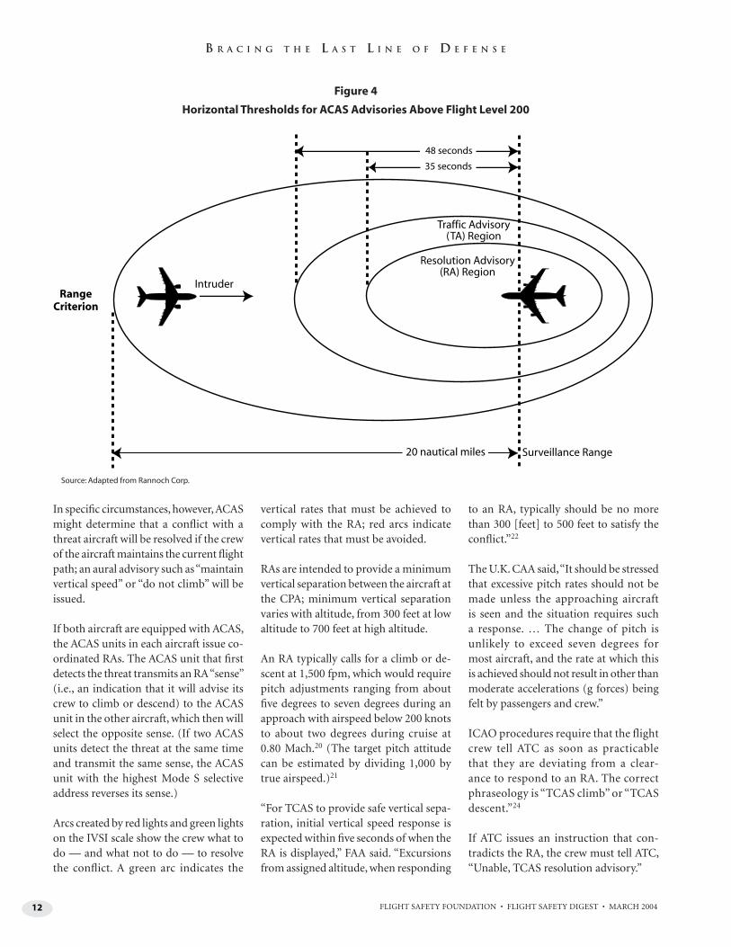
TAs and RAs are issued when the CPA of another aircraft is projected to be within the aircraft’s pro-tected volume. The advisories are based on time. Below 1,000 feet, a TA is issued when another air-craft (an “intruder”) is projected to reach the CPA within 20 seconds. The advisory times increase with altitude. Above FL 200, for example, a TA is issued when the intruder is projected to reach the CPA within 48 seconds (Figure 4, page 12).
No RAs are issued below 1,000 feet. Five seconds are added to RA-issuance times to accommodate fl ight crew response. RA-issuance times increase with alti-tude, from 15 seconds between 1,000 feet and 2,350 feet, to 35 seconds above FL 200. The aircraft for which an RA is issued is called a “threat aircraft.”
Crew Receives Visual and Aural Advisories
Aircraft that are being tracked by ACAS are depicted on the display as colored shapes.
“Proximate” traffi c — aircraft 1,200 feet above or below the aircraft’s altitude or more than six nau-tical miles (11 kilometers) away — are displayed as open white diamonds or open cyan (greenish blue) diamonds.16
The relative altitudes of the tracked aircraft with alti-tude-reporting transponders are shown next to their symbols in digital format, rounded off to the nearest hundred feet. For example, “05” would indicate that the other aircraft is 500 feet above; “–06” would indi-cate that the other aircraft is 600 feet below.
An arrow pointing up or down also would be dis-played next to the symbol to indicate that the other aircraft is climbing or descending, respectively, at a rate greater than 500 fpm.
If a proximate aircraft comes within 1,200 feet of the aircraft’s altitude or within six nautical miles, the symbol changes to either a closed white dia-mond or a closed cyan diamond.
Intruders are displayed as closed amber circles; and if the aircraft is above 500 feet above ground level (AGL), an aural advisory, “traffi c, traffi c,” is issued.
“TAs are intended to alert pilots to the possibility of an [RA], to enhance situational awareness and to assist in visual acquisition of confl icting traffi c,” said ICAO.17 “On receipt of a TA, pilots shall use all available information to prepare for appropriate action if an RA occurs.”
The fl ight crew should not maneuver the aircraft in response to a TA.
“Respond to TAs by attempting to establish vi-sual contact with the intruder aircraft and other aircraft which may be in the vicinity,” FAA said.18 “Coordinate to the degree possible with other crewmembers to assist in searching for traffi c. Do not deviate from an assigned clearance based only on TA information.”
The U.K. Civil Aviation Authority (CAA) said, “ACAS equipment [is] not capable of resolving the bearing, heading or vertical rates of intrud-ers accurately. For this reason, pilots should not attempt to maneuver solely on the basis of TA information.”19
Five Seconds to Respond
When another aircraft becomes a threat, the symbol changes to a closed red square, and
the fl ight crew receives an aural advisory — typi-cally, “climb, climb,” or “descend, descend” or “adjust vertical speed.”
700 feet
700 feet
850 feet
850 feet
Traffic Advisory (TA) Region
Resolution Advisory (RA) Region
Figure 3
Vertical Thresholds for ACAS Advisories
Source: Adapted from Rannoch Corp.
12 FLIGHT SAFETY FOUNDATION • FLIGHT SAFETY DIGEST • MARCH 2004
B R A C I N G T H E L A S T L I N E O F D E F E N S E
In specifi c circumstances, however, ACAS might determine that a confl ict with a threat aircraft will be resolved if the crew of the aircraft maintains the current fl ight path; an aural advisory such as “maintain vertical speed” or “do not climb” will be issued.
If both aircraft are equipped with ACAS, the ACAS units in each aircraft issue co-ordinated RAs. The ACAS unit that fi rst detects the threat transmits an RA “sense” (i.e., an indication that it will advise its crew to climb or descend) to the ACAS unit in the other aircraft, which then will select the opposite sense. (If two ACAS units detect the threat at the same time and transmit the same sense, the ACAS unit with the highest Mode S selective address reverses its sense.)
Arcs created by red lights and green lights on the IVSI scale show the crew what to do — and what not to do — to resolve the confl ict. A green arc indicates the
vertical rates that must be achieved to comply with the RA; red arcs indicate vertical rates that must be avoided.
RAs are intended to provide a minimum vertical separation between the aircraft at the CPA; minimum vertical separation varies with altitude, from 300 feet at low altitude to 700 feet at high altitude.
An RA typically calls for a climb or de-scent at 1,500 fpm, which would require pitch adjustments ranging from about fi ve degrees to seven degrees during an approach with airspeed below 200 knots to about two degrees during cruise at 0.80 Mach.20 (The target pitch attitude can be estimated by dividing 1,000 by true airspeed.)21
“For TCAS to provide safe vertical sepa-ration, initial vertical speed response is expected within fi ve seconds of when the RA is displayed,” FAA said. “Excursions from assigned altitude, when responding
to an RA, typically should be no more than 300 [feet] to 500 feet to satisfy the confl ict.”22
The U.K. CAA said, “It should be stressed that excessive pitch rates should not be made unless the approaching aircraft is seen and the situation requires such a response. … The change of pitch is unlikely to exceed seven degrees for most aircraft, and the rate at which this is achieved should not result in other than moderate accelerations (g forces) being felt by passengers and crew.”
ICAO procedures require that the flight crew tell ATC as soon as practicable that they are deviating from a clear-ance to respond to an RA. The correct phraseology is “TCAS climb” or “TCAS descent.”24
If ATC issues an instruction that con-tradicts the RA, the crew must tell ATC, “Unable, TCAS resolution advisory.”
48 seconds
35 seconds
Traffic Advisory(TA) Region
Resolution Advisory(RA) Region
20 nautical miles
IntruderRange
Criterion
Surveillance Range
Figure 4
Horizontal Thresholds for ACAS Advisories Above Flight Level 200
Source: Adapted from Rannoch Corp.
13FLIGHT SAFETY FOUNDATION • FLIGHT SAFETY DIGEST • MARCH 2004
B R A C I N G T H E L A S T L I N E O F D E F E N S E
“Once an aircraft departs from its ATC clearance in compliance with an RA, the controller ceases to be responsible for providing separation between that aircraft and any other aircraft af-fected by the RA maneuver,” said Kevin Moore, an ICAO Navigation Bureau technical offi cer and secretary of the ICAO Operations Panel.25 “Procedures require that the pilot notify ATC as soon as practicable of any deviation from an ATC instruction or clearance in response to an RA, including the direction of the maneuver and an indication when it is over.
“When aware that an aircraft is maneu-vering in response to an RA, the con-troller must not attempt to modify the aircraft fl ight path, but can provide traffi c information. The controller resumes re-sponsibility for providing separation for all the affected aircraft after the pilots involved have advised that their aircraft are resuming the current clearance or will comply with an alternative clearance is-sued by the controller.”
An RA May Change to Resolve Confl ict
A “corrective RA” will be issued if ACAS projects that minimum ver-
tical separation will not be achieved at the CPA. The crew will receive an aural advisory to “increase climb” or to “in-crease descent.” A corrective RA typically requires the vertical rate to be increased to 2,500 fpm.
In specifi c circumstances, an RA might be reversed. For example, if a descent RA was issued to avoid a confl ict with a threat aircraft in level fl ight but the threat aircraft suddenly begins a descent also, ACAS will instruct the crew of the aircraft to “climb, climb now.”
A “reversed RA” is based on crew response within 2.5 seconds. The crew should not exceed 0.3 g when changing from a climb to a descent, or vice versa.
“If a reversed-sense RA is given, no time should be lost initiating the change of pitch attitude, care being taken not to use excessive vigor,” the U.K. CAA said.
When the confl ict has been resolved, the aural advisory “clear of confl ict” is issued, the green lights and red lights disappear from the IVSI, and the symbol of the threat aircraft changes from a red square to a yellow circle, and eventually to a white or cyan diamond.
The fl ight crew must “promptly return to the terms of the ATC instruction or clearance when the confl ict is resolved and notify ATC when returning to the current clearance,” ICAO said.26
An example of the correct phraseology is: “Returning to Flight Level 350.” In this case, after leveling at FL 350, the crew should tell ATC, “TCAS climb [or descent] completed, Flight Level 350 resumed.”
ICAO recommends that pilots who fl y ACAS-equipped aircraft receive initial training and recurrent training. The recurrent training should include prac-ticing RA maneuvers every four years in a fl ight simulator or every two years in a computer-based trainer.
Eurocontrol Cites Misuse of ACAS
The European Organization for the Safety of Air Navigation (Eurocon-
trol) in 1995 adopted a policy requiring ACAS to be installed by Jan. 1, 2000, in turbine airplanes with MTOWs of more than 15,000 kilograms or with more than 30 passenger seats. The policy also requires ACAS to be installed by Jan. 1, 2005, in turbine airplanes with MTOWs of more than 5,700 kilograms or with more than 19 passenger seats.
Monitoring of ACAS performance in Europe has shown some recurring problems.27 Eurocontrol said that the following are examples:
• “An RA sometimes causes pilots to deviate from their ATC clearance far more than necessary or required. Deviations greater than 1,000 feet have been recorded, and the mean deviation is around 650 feet;
• “Pilots are often slow to report the initial deviation to the controller and subsequently to return to the given ATC clearance. The official phrase-ology is sometimes not used, and a distracting and disturbing dialogue about the event may begin on the frequency; [and,]
• “Some pilots request information or refuse a clearance based upon aircraft data on the traffic display. … Aircraft have also been observed turning, on the basis of the data shown on the traffic display, without visual acquisition by the aircrew.”
Eurocontrol said that despite the prob-lems, ACAS has been beneficial (see “ACAS Provides an Effective Safety Net When Procedures Are Followed,” page 15).
“The evaluation of [ACAS] performance in Europe and the monitoring of its im-plementation have demonstrated that this equipment has already improved fl ight safety,” Eurocontrol said. ■
Notes
1. International Civil Aviation Organization (ICAO). Procedures for Air Navigation Services — Aircraft Operations (PANS-OPS). Volume 1, Flight Procedures. Chapter 3, Operation of ACAS Equipment. 3.2, “Use of ACAS Indications.”
2. ICAO Secretariat. “Airborne Collision Avoidance System II (ACAS II).” Eleventh Air Navigation Conference. Montreal, Canada. Sept. 22–Oct. 3, 2003.
3. Bundesstelle fur Flugunfalluntersuchung (BFU). Status Report AX001-1/-2/02. August 2002.
4. Airclaims. World Aircraft Accident Summary. (Issue 131): A02:17.
14 FLIGHT SAFETY FOUNDATION • FLIGHT SAFETY DIGEST • MARCH 2004
B R A C I N G T H E L A S T L I N E O F D E F E N S E
5. Aircraft and Railway Accidents Investigation Commission of Japan. Aircraft Accident Investigation Report 2002-5, Japan Airlines Boeing 747-400, JA8904 (A Near Midair Collision With a Douglas DC-10-40 of Japan Airlines, JA8546). The English-language version of the report contains 276 pages, with illustrations and appendixes.
6. ICAO, PANS-OPS. Volume 1. Chapter 3. 3.2.
7. Ibid.
8. ICAO. International Standards and Recommended Practices. Annex 6 to the Convention on International Civil Aviation: Operation of Aircraft. Part 1, International Commercial Air Transport — Aeroplanes. Chapter 6, Aeroplane Instruments, Equipment and Flight Documents. 6.18, “Aeroplanes required to be equipped with an airborne collision avoidance system (ACAS II).”
9. ICAO. PANS-OPS. Volume 1. Chapter 3. 3.2. Attachment A to Part VIII, “ACAS II Training Guidelines for Pilots.”
10. Enhanced ground-proximity warning system (EGPWS) and ground collision avoidance system are other terms used to describe terrain awareness and warning system (TAWS) equipment. TAWS is the term used by the European Joint Aviation Authorities and the U.S. Federal Aviation Administration to describe equipment meeting ICAO standards and recommendations for GPWS equipment that provides predictive terrain-hazard warnings.
11. European Organization for the Safety of Air Navigaion (Eurocontrol). ACAS II. May 2000.
12. U.K. Civil Aviation Authority (CAA). Civil Aviation Publication (CAP) 479. World Airline Accident Summary, Volume 1: 1946 to 1974 Inclusive. 10/56.
13. U.S. National Transportation Safety Board. Aircraft Accident Report: Collision of Aeronaves de Mexico, S.A., McDonnell Douglas DC-9-32, XA-JED, and Piper PA-28-151, N4891F, Cerritos, California, August 31, 1986. NTSB/AAR-87/07.
14. U.S. Federal Aviation Administration (FAA). Federal Aviation Regulations (FARs) Part 121, Operating Requirements: Domestic, Flag, and Supplemental Operations. Subpart K, Instrument and
Equipment Requirements. Part 121 356, “Traffi c Alert and Collision Avoidance System.”
15. Eurocontrol.
16. Honeywell. TCAS II/ACAS II Collision Avoidance System User’s Manual. ACS-5059, Revision 5. February 2000.
17. ICAO. PANS-OPS. Volume 1. Chapter 3. 3.2.
18. FAA. Advisory Circular (AC) 120-55B. Air Carrier Operational Approval and Use of TCAS II. Oct. 22, 2001.
19. U.K. CAA. CAP 579, Airborne Collision Avoidance System (ACAS): Guidance Material. Sept. 6, 2002.
20. FAA. AC 120-55B.
21. Joint Aviation Authorities. Leafl et No. 11, Guidance for Operators on Training Programmes for the Use of Airborne Collision Avoidance Systems (ACAS). June 1998.
22. FAA. AC 120-55B.
23. U.K. CAA. CAP 579.
24. ICAO. Procedures for Air Navigation Services — Air Traffi c Management (PANS-ATM). Chapter 12, Phraseologies. 12.3.1, “General.”
25. Moore, Kevin. “Compliance With ACAS RAs Critical Even if They Confl ict With ATC Instructions.” ICAO Journal Volume 58 (June 2003).
26. ICAO, PANS-OPS. Volume 1. Chapter 3. 3.2.
27. Eurocontrol.
Further Reading From FSF Publications
FSF Editorial Staff. “Audit of ATC Operational Errors Prompts Call for Mandatory Remedial Training.” Airport Operations Volume 29 (September–October 2003).
FSF Editorial Staff. “Traffic Conflict Near Australian Airport Prompts Call for Airborne Collision Avoidance Sys-tems.” Airport Operations Volume 27 (July–August 2001).
FSF Editorial Staff. “See-and-avoid De-fi ciencies Cited in Collision of Fighter and Light Airplane.” Accident Prevention Volume 57 (September 2000).
FSF Editorial Staff. “Midair Collisions Prompt Recommendations for Improve-ment of ATC Radar Systems.” Airport Operations Volume 25 (November–December 1999).
FSF Editorial Staff. “Factors in Near Midair Collisions Show Controller-Pilot Interdependence.” Airport Opera-tions Volume 25 (May–June 1999).
FSF Editorial Staff. “Boeing 737 Pilot Flying Selects Incorrect Altitude in Hold-ing Pattern, Causes Dangerous Loss of Separation with MD-81.” Accident Pre-vention Volume 55 (April 1998).
Stamford Krause, Shari. “Collision Avoid-ance Must Go Beyond ‘See and Avoid’ to ‘Search and Detect.’” Flight Safety Digest Volume 16 (May 1997).
U.S. National Transportation Safety Board. “Air Traffi c Control Equipment Outages.” Flight Safety Digest Volume 15 (February 1996).
Sumwalt, Robert L. “Altitude Aware-ness Programs Can Reduce Altitude Deviations.” Flight Safety Digest Volume 14 (December 1995).
Mellone, V.J.; Frank, S.M. “The U.S. Air Traffi c Control System Wrestles with the Infl uence of TCAS.” Flight Safety Digest Volume 12 (November 1993).
FSF Editorial Staff. “Interim Reports Give TCAS Mixed Reviews.” Airport Operations Volume 18 (September–October 1992).
15FLIGHT SAFETY FOUNDATION • FLIGHT SAFETY DIGEST • MARCH 2004
A C A S P R O V I D E S A N E F F E C T I V E S A F E T Y N E T
ACAS Provides an Effective Safety Net When Procedures Are FollowedAirborne collision avoidance system performance monitoring in Europe shows that the
significant safety benefit of ACAS can be diminished by improper procedures, such as
failures to comply with resolution advisories.
— JOHN LAW, EUROCONTROL
Recent safety studies by the European Organization for the Safety of Air Navigation (Eurocontrol) have con-fi rmed the signifi cant safety benefi t
afforded by the airborne collision avoidance sys-tem (ACAS; also called the traffi c-alert and colli-sion avoidance system [TCAS II]), but they also have revealed that it can be degraded by improper procedures, such as defi cient response to resolu-tion advisories (RAs). Operational monitoring programs have highlighted, in numerous actual events, the signifi cant ACAS contribution to im-proved fl ight safety. It has also been shown that in some events where the responses of pilots to RAs have been inadequate and where maneuvers op-posite to the RAs have been identifi ed, the safety benefi t is diminished.
Events 1–5 show that inadequate response to RAs degrades safety. Nevertheless, events 6 and 7 illustrate that accurate response to RAs greatly improves safety.
Follow the RA
Flight crews should operate ACAS at all times, and all fl ight crews should follow RAs. Training
courses should be reviewed to ensure that these areas are addressed.
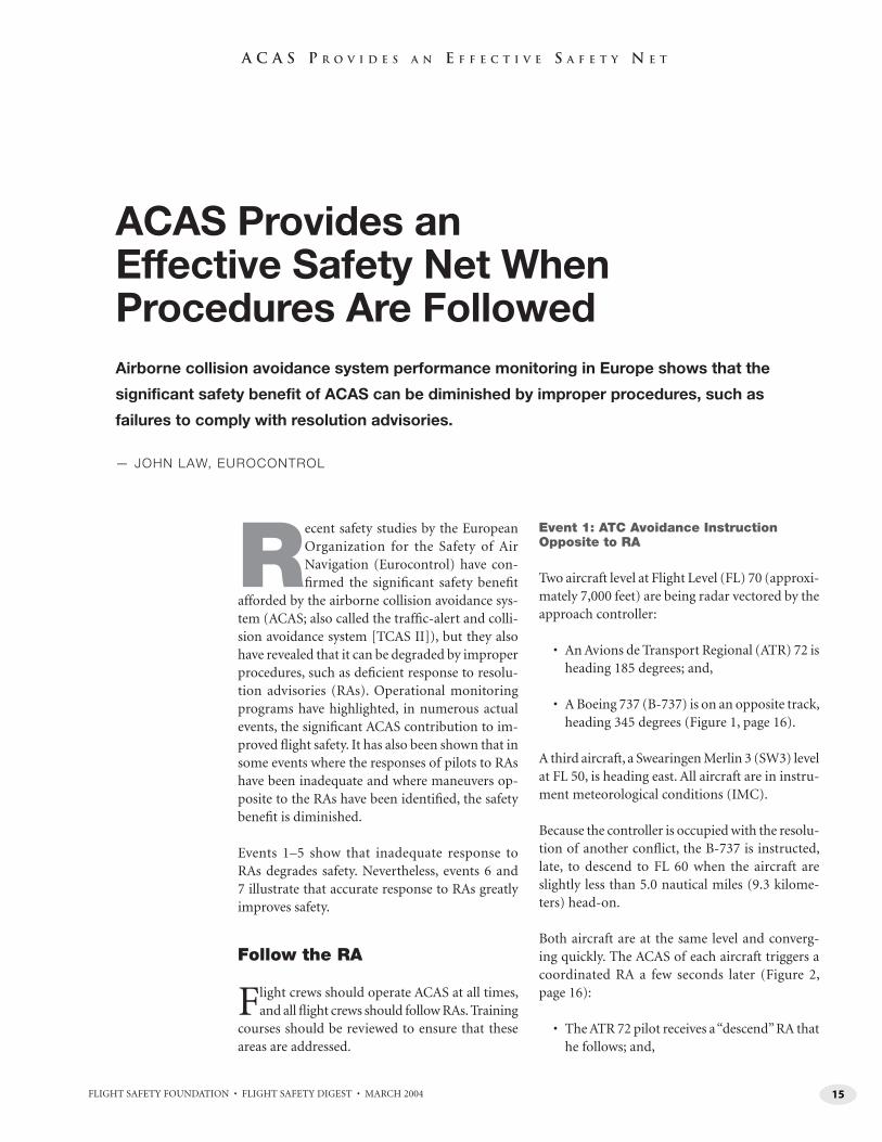
Event 1: ATC Avoidance Instruction Opposite to RA
Two aircraft level at Flight Level (FL) 70 (approxi-mately 7,000 feet) are being radar vectored by the approach controller:
• An Avions de Transport Regional (ATR) 72 is heading 185 degrees; and,
• A Boeing 737 (B-737) is on an opposite track, heading 345 degrees (Figure 1, page 16).
A third aircraft, a Swearingen Merlin 3 (SW3) level at FL 50, is heading east. All aircraft are in instru-ment meteorological conditions (IMC).
Because the controller is occupied with the resolu-tion of another confl ict, the B-737 is instructed, late, to descend to FL 60 when the aircraft are slightly less than 5.0 nautical miles (9.3 kilome-ters) head-on.
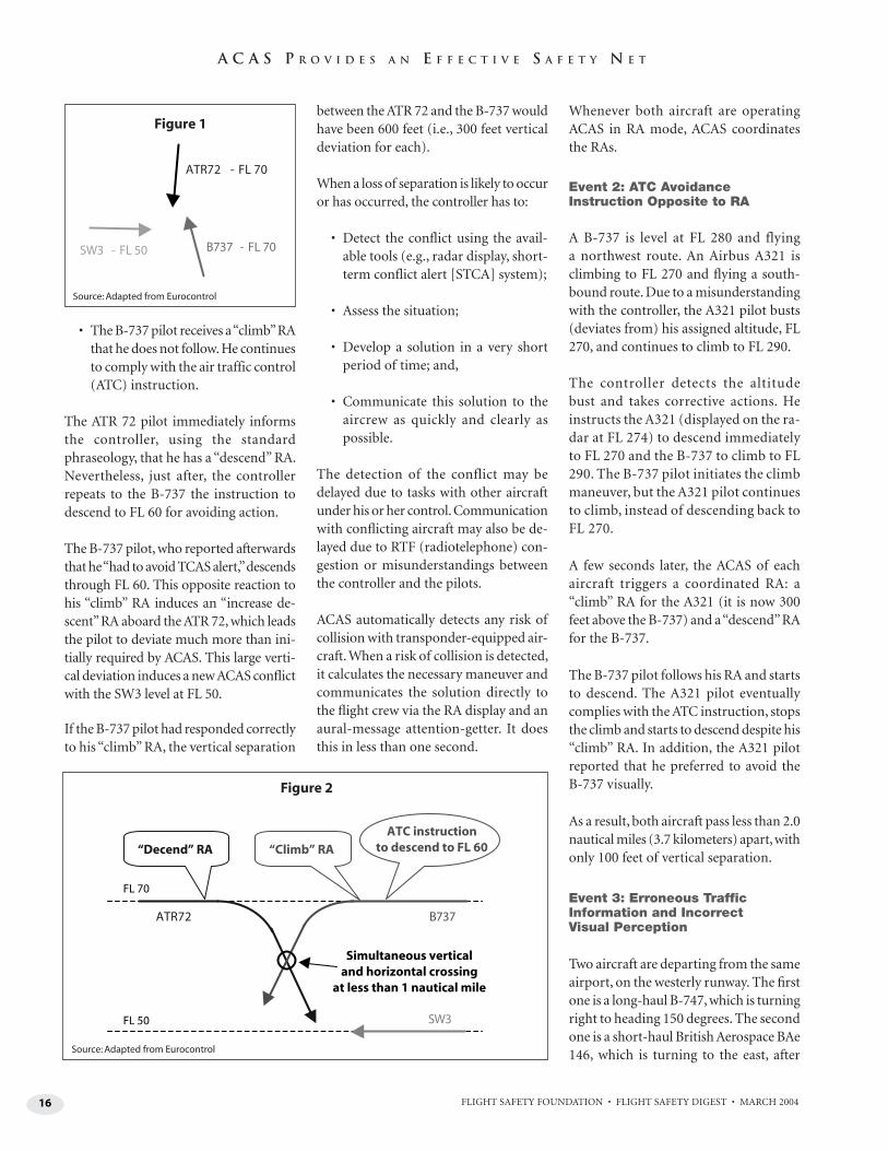
Both aircraft are at the same level and converg-ing quickly. The ACAS of each aircraft triggers a coordinated RA a few seconds later (Figure 2, page 16):
• The ATR 72 pilot receives a “descend” RA that he follows; and,
16 FLIGHT SAFETY FOUNDATION • FLIGHT SAFETY DIGEST • MARCH 2004
A C A S P R O V I D E S A N E F F E C T I V E S A F E T Y N E T
• The B-737 pilot receives a “climb” RA that he does not follow. He continues to comply with the air traffic control (ATC) instruction.
The ATR 72 pilot immediately informs the controller, using the standard phraseology, that he has a “descend” RA. Nevertheless, just after, the controller repeats to the B-737 the instruction to descend to FL 60 for avoiding action.
The B-737 pilot, who reported afterwards that he “had to avoid TCAS alert,” descends through FL 60. This opposite reaction to his “climb” RA induces an “increase de-scent” RA aboard the ATR 72, which leads the pilot to deviate much more than ini-tially required by ACAS. This large verti-cal deviation induces a new ACAS confl ict with the SW3 level at FL 50.
If the B-737 pilot had responded correctly to his “climb” RA, the vertical separation
between the ATR 72 and the B-737 would have been 600 feet (i.e., 300 feet vertical deviation for each).
When a loss of separation is likely to occur or has occurred, the controller has to:
• Detect the conflict using the avail-able tools (e.g., radar display, short-term conflict alert [STCA] system);
• Assess the situation;
• Develop a solution in a very short period of time; and,
• Communicate this solution to the aircrew as quickly and clearly as possible.
The detection of the conflict may be delayed due to tasks with other aircraft under his or her control. Communication with confl icting aircraft may also be de-layed due to RTF (radiotelephone) con-gestion or misunderstandings between the controller and the pilots.
ACAS automatically detects any risk of collision with transponder-equipped air-craft. When a risk of collision is detected, it calculates the necessary maneuver and communicates the solution directly to the fl ight crew via the RA display and an aural-message attention-getter. It does this in less than one second.
Whenever both aircraft are operating ACAS in RA mode, ACAS coordinates the RAs.
Event 2: ATC Avoidance Instruction Opposite to RA
A B-737 is level at FL 280 and flying a northwest route. An Airbus A321 is climbing to FL 270 and fl ying a south-bound route. Due to a misunderstanding with the controller, the A321 pilot busts (deviates from) his assigned altitude, FL 270, and continues to climb to FL 290.
The controller detects the altitude bust and takes corrective actions. He instructs the A321 (displayed on the ra-dar at FL 274) to descend immediately to FL 270 and the B-737 to climb to FL 290. The B-737 pilot initiates the climb maneuver, but the A321 pilot continues to climb, instead of descending back to FL 270.
A few seconds later, the ACAS of each aircraft triggers a coordinated RA: a “climb” RA for the A321 (it is now 300 feet above the B-737) and a “descend” RA for the B-737.
The B-737 pilot follows his RA and starts to descend. The A321 pilot eventually complies with the ATC instruction, stops the climb and starts to descend despite his “climb” RA. In addition, the A321 pilot reported that he preferred to avoid the B-737 visually.
As a result, both aircraft pass less than 2.0 nautical miles (3.7 kilometers) apart, with only 100 feet of vertical separation.
Event 3: Erroneous Traffi c Information and Incorrect Visual Perception
Two aircraft are departing from the same airport, on the westerly runway. The fi rst one is a long-haul B-747, which is turning right to heading 150 degrees. The second one is a short-haul British Aerospace BAe 146, which is turning to the east, after
Figure 2
ATR72 - FL 70
B737 - FL 70SW3 - FL 50
Figure 1
FL 70
FL 50
ATR72 B737
SW3
“Decend” RA “Climb” RA
ATC instructionto descend to FL 60
Simultaneous verticaland horizontal crossing
at less than 1 nautical mile
Source: Adapted from Eurocontrol
Source: Adapted from Eurocontrol
17FLIGHT SAFETY FOUNDATION • FLIGHT SAFETY DIGEST • MARCH 2004
A C A S P R O V I D E S A N E F F E C T I V E S A F E T Y N E T
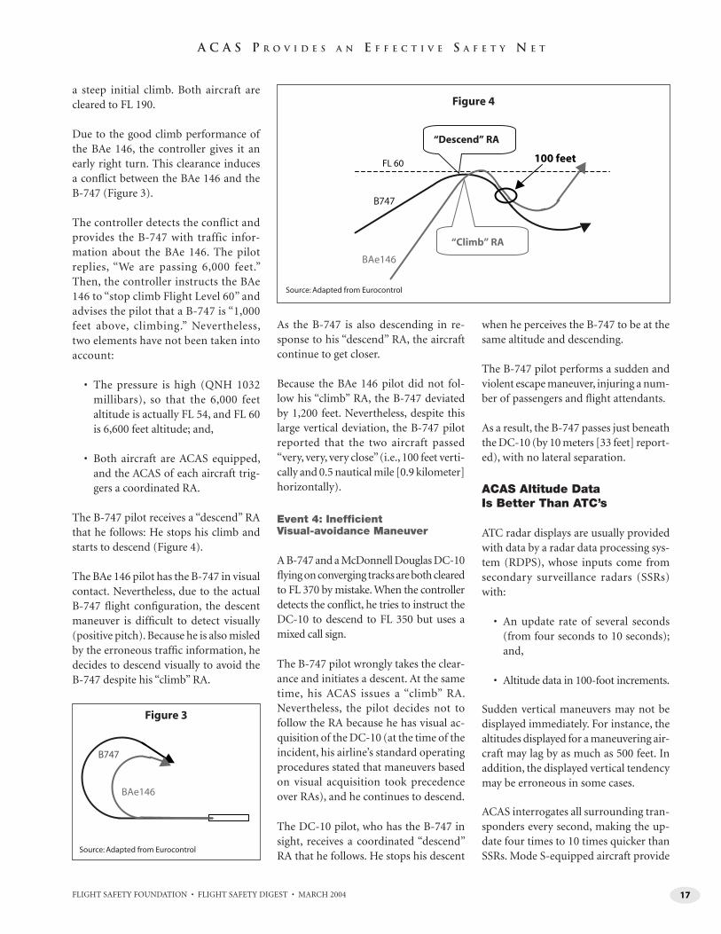
a steep initial climb. Both aircraft are cleared to FL 190.
Due to the good climb performance of the BAe 146, the controller gives it an early right turn. This clearance induces a confl ict between the BAe 146 and the B-747 (Figure 3).
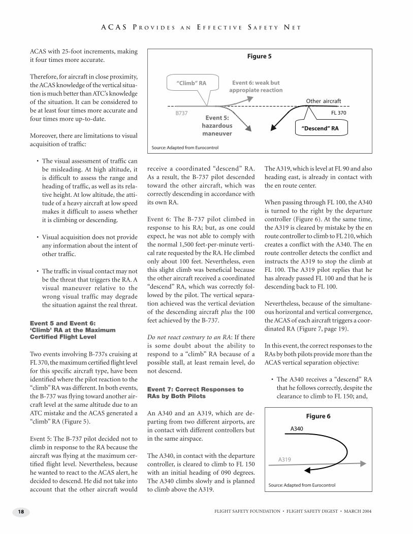
The controller detects the conflict and provides the B-747 with traffic infor-mation about the BAe 146. The pilot replies, “We are passing 6,000 feet.” Then, the controller instructs the BAe 146 to “stop climb Flight Level 60” and advises the pilot that a B-747 is “1,000 feet above, climbing.” Nevertheless, two elements have not been taken into account:
• The pressure is high (QNH 1032 millibars), so that the 6,000 feet altitude is actually FL 54, and FL 60 is 6,600 feet altitude; and,
• Both aircraft are ACAS equipped, and the ACAS of each aircraft trig-gers a coordinated RA.
The B-747 pilot receives a “descend” RA that he follows: He stops his climb and starts to descend (Figure 4).
The BAe 146 pilot has the B-747 in visual contact. Nevertheless, due to the actual B-747 fl ight confi guration, the descent maneuver is diffi cult to detect visually (positive pitch). Because he is also misled by the erroneous traffi c information, he decides to descend visually to avoid the B-747 despite his “climb” RA.
As the B-747 is also descending in re-sponse to his “descend” RA, the aircraft continue to get closer.
Because the BAe 146 pilot did not fol-low his “climb” RA, the B-747 deviated by 1,200 feet. Nevertheless, despite this large vertical deviation, the B-747 pilot reported that the two aircraft passed “very, very, very close” (i.e., 100 feet verti-cally and 0.5 nautical mile [0.9 kilometer] horizontally).
Event 4: Ineffi cient Visual-avoidance Maneuver
A B-747 and a McDonnell Douglas DC-10 fl ying on converging tracks are both cleared to FL 370 by mistake. When the controller detects the confl ict, he tries to instruct the DC-10 to descend to FL 350 but uses a mixed call sign.
The B-747 pilot wrongly takes the clear-ance and initiates a descent. At the same time, his ACAS issues a “climb” RA. Nevertheless, the pilot decides not to follow the RA because he has visual ac-quisition of the DC-10 (at the time of the incident, his airline’s standard operating procedures stated that maneuvers based on visual acquisition took precedence over RAs), and he continues to descend.
The DC-10 pilot, who has the B-747 in sight, receives a coordinated “descend” RA that he follows. He stops his descent
when he perceives the B-747 to be at the same altitude and descending.
The B-747 pilot performs a sudden and violent escape maneuver, injuring a num-ber of passengers and fl ight attendants.
As a result, the B-747 passes just beneath the DC-10 (by 10 meters [33 feet] report-ed), with no lateral separation.
ACAS Altitude Data Is Better Than ATC’s
ATC radar displays are usually provided with data by a radar data processing sys-tem (RDPS), whose inputs come from secondary surveillance radars (SSRs) with:
• An update rate of several seconds (from four seconds to 10 seconds); and,
• Altitude data in 100-foot increments.
Sudden vertical maneuvers may not be displayed immediately. For instance, the altitudes displayed for a maneuvering air-craft may lag by as much as 500 feet. In addition, the displayed vertical tendency may be erroneous in some cases.
ACAS interrogates all surrounding tran-sponders every second, making the up-date four times to 10 times quicker than SSRs. Mode S-equipped aircraft provide
B747
BAe146
Figure 3
BAe146
B747
FL 60
“Descend” RA
100 feet
“Climb” RA
Figure 4
Source: Adapted from Eurocontrol
Source: Adapted from Eurocontrol
18 FLIGHT SAFETY FOUNDATION • FLIGHT SAFETY DIGEST • MARCH 2004
A C A S P R O V I D E S A N E F F E C T I V E S A F E T Y N E T
ACAS with 25-foot increments, making it four times more accurate.
Therefore, for aircraft in close proximity, the ACAS knowledge of the vertical situa-tion is much better than ATC’s knowledge of the situation. It can be considered to be at least four times more accurate and four times more up-to-date.
Moreover, there are limitations to visual acquisition of traffi c:
• The visual assessment of traffic can be misleading. At high altitude, it is difficult to assess the range and heading of traffic, as well as its rela-tive height. At low altitude, the atti-tude of a heavy aircraft at low speed makes it difficult to assess whether it is climbing or descending.
• Visual acquisition does not provide any information about the intent of other traffic.
• The traffic in visual contact may not be the threat that triggers the RA. A visual maneuver relative to the wrong visual traffic may degrade the situation against the real threat.
Event 5 and Event 6: ‘Climb’ RA at the Maximum Certifi ed Flight Level
Two events involving B-737s cruising at FL 370, the maximum certifi ed fl ight level for this specifi c aircraft type, have been identifi ed where the pilot reaction to the “climb” RA was different. In both events, the B-737 was fl ying toward another air-craft level at the same altitude due to an ATC mistake and the ACAS generated a “climb” RA (Figure 5).
Event 5: The B-737 pilot decided not to climb in response to the RA because the aircraft was fl ying at the maximum cer-tifi ed fl ight level. Nevertheless, because he wanted to react to the ACAS alert, he decided to descend. He did not take into account that the other aircraft would
receive a coordinated “descend” RA. As a result, the B-737 pilot descended toward the other aircraft, which was correctly descending in accordance with its own RA.
Event 6: The B-737 pilot climbed in response to his RA; but, as one could expect, he was not able to comply with the normal 1,500 feet-per-minute verti-cal rate requested by the RA. He climbed only about 100 feet. Nevertheless, even this slight climb was benefi cial because the other aircraft received a coordinated “descend” RA, which was correctly fol-lowed by the pilot. The vertical separa-tion achieved was the vertical deviation of the descending aircraft plus the 100 feet achieved by the B-737.
Do not react contrary to an RA: If there is some doubt about the ability to respond to a “climb” RA because of a possible stall, at least remain level, do not descend.
Event 7: Correct Responses to RAs by Both Pilots
An A340 and an A319, which are de-parting from two different airports, are in contact with different controllers but in the same airspace.
The A340, in contact with the departure controller, is cleared to climb to FL 150 with an initial heading of 090 degrees. The A340 climbs slowly and is planned to climb above the A319.
The A319, which is level at FL 90 and also heading east, is already in contact with the en route center.
When passing through FL 100, the A340 is turned to the right by the departure controller (Figure 6). At the same time, the A319 is cleared by mistake by the en route controller to climb to FL 210, which creates a confl ict with the A340. The en route controller detects the confl ict and instructs the A319 to stop the climb at FL 100. The A319 pilot replies that he has already passed FL 100 and that he is descending back to FL 100.
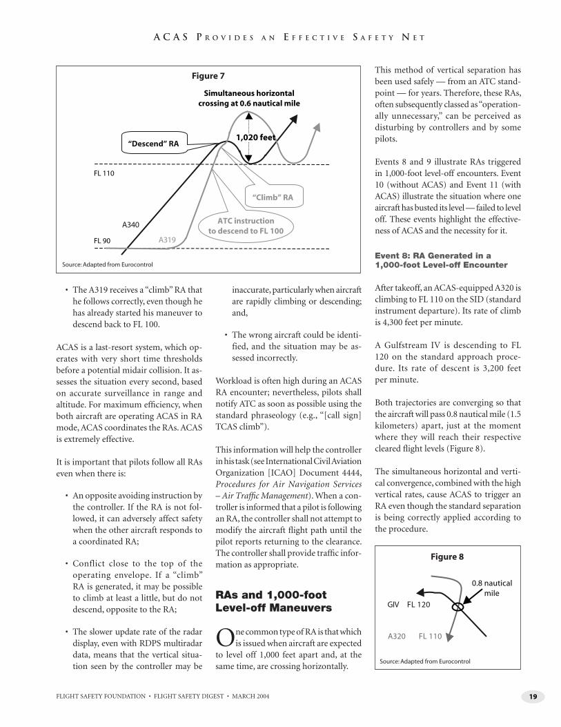
Nevertheless, because of the simultane-ous horizontal and vertical convergence, the ACAS of each aircraft triggers a coor-dinated RA (Figure 7, page 19).
In this event, the correct responses to the RAs by both pilots provide more than the ACAS vertical separation objective:
• The A340 receives a “descend” RA that he follows correctly, despite the clearance to climb to FL 150; and,
Figure 5
A340
A319
Source: Adapted from Eurocontrol
Figure 6
Source: Adapted from Eurocontrol
FL 370B737
Other aircraft
Event 5:hazardousmaneuver
Event 6: weak butappropiate reaction
“Climb” RA
“Descend” RA
19FLIGHT SAFETY FOUNDATION • FLIGHT SAFETY DIGEST • MARCH 2004
A C A S P R O V I D E S A N E F F E C T I V E S A F E T Y N E T
• The A319 receives a “climb” RA that he follows correctly, even though he has already started his maneuver to descend back to FL 100.
ACAS is a last-resort system, which op-erates with very short time thresholds before a potential midair collision. It as-sesses the situation every second, based on accurate surveillance in range and altitude. For maximum effi ciency, when both aircraft are operating ACAS in RA mode, ACAS coordinates the RAs. ACAS is extremely effective.
It is important that pilots follow all RAs even when there is:
• An opposite avoiding instruction by the controller. If the RA is not fol-lowed, it can adversely affect safety when the other aircraft responds to a coordinated RA;
• Conflict close to the top of the operating envelope. If a “climb” RA is generated, it may be possible to climb at least a little, but do not descend, opposite to the RA;
• The slower update rate of the radar display, even with RDPS multiradar data, means that the vertical situa-tion seen by the controller may be
inaccurate, particularly when aircraft are rapidly climbing or descending; and,
• The wrong aircraft could be identi-fied, and the situation may be as-sessed incorrectly.
Workload is often high during an ACAS RA encounter; nevertheless, pilots shall notify ATC as soon as possible using the standard phraseology (e.g., “[call sign] TCAS climb”).
This information will help the controller in his task (see International Civil Aviation Organization [ICAO] Document 4444, Procedures for Air Navigation Services – Air Traffi c Management). When a con-troller is informed that a pilot is following an RA, the controller shall not attempt to modify the aircraft fl ight path until the pilot reports returning to the clearance. The controller shall provide traffi c infor-mation as appropriate.
RAs and 1,000-foot Level-off Maneuvers
One common type of RA is that which is issued when aircraft are expected
to level off 1,000 feet apart and, at the same time, are crossing horizontally.
This method of vertical separation has been used safely — from an ATC stand-point — for years. Therefore, these RAs, often subsequently classed as “operation-ally unnecessary,” can be perceived as disturbing by controllers and by some pilots.
Events 8 and 9 illustrate RAs triggered in 1,000-foot level-off encounters. Event 10 (without ACAS) and Event 11 (with ACAS) illustrate the situation where one aircraft has busted its level — failed to level off. These events highlight the effective-ness of ACAS and the necessity for it.
Event 8: RA Generated in a 1,000-foot Level-off Encounter
After takeoff, an ACAS-equipped A320 is climbing to FL 110 on the SID (standard instrument departure). Its rate of climb is 4,300 feet per minute.
A Gulfstream IV is descending to FL 120 on the standard approach proce-dure. Its rate of descent is 3,200 feet per minute.
Both trajectories are converging so that the aircraft will pass 0.8 nautical mile (1.5 kilometers) apart, just at the moment where they will reach their respective cleared fl ight levels (Figure 8).
The simultaneous horizontal and verti-cal convergence, combined with the high vertical rates, cause ACAS to trigger an RA even though the standard separation is being correctly applied according to the procedure.
FL 90
FL 110
A340
A319
Simultaneous horizontalcrossing at 0.6 nautical mile
1,020 feet“Descend” RA
ATC instructionto descend to FL 100
“Climb” RA
Figure 7
GIV FL 120
A320 FL 110
0.8 nauticalmile
Figure 8
Source: Adapted from Eurocontrol
Source: Adapted from Eurocontrol
20 FLIGHT SAFETY FOUNDATION • FLIGHT SAFETY DIGEST • MARCH 2004
A C A S P R O V I D E S A N E F F E C T I V E S A F E T Y N E T
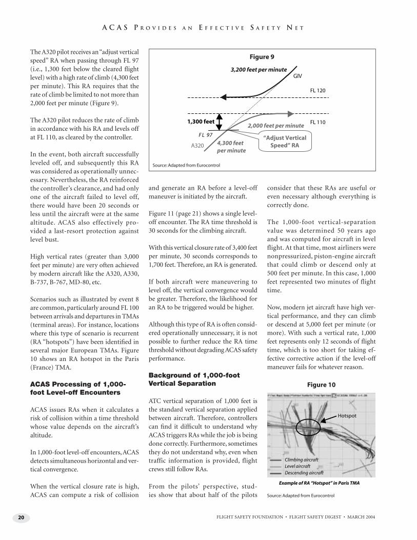
The A320 pilot receives an “adjust vertical speed” RA when passing through FL 97 (i.e., 1,300 feet below the cleared fl ight level) with a high rate of climb (4,300 feet per minute). This RA requires that the rate of climb be limited to not more than 2,000 feet per minute (Figure 9).
The A320 pilot reduces the rate of climb in accordance with his RA and levels off at FL 110, as cleared by the controller.
In the event, both aircraft successfully leveled off, and subsequently this RA was considered as operationally unnec-essary. Nevertheless, the RA reinforced the controller’s clearance, and had only one of the aircraft failed to level off, there would have been 20 seconds or less until the aircraft were at the same altitude. ACAS also effectively pro-vided a last-resort protection against level bust.
High vertical rates (greater than 3,000 feet per minute) are very often achieved by modern aircraft like the A320, A330, B-737, B-767, MD-80, etc.
Scenarios such as illustrated by event 8 are common, particularly around FL 100 between arrivals and departures in TMAs (terminal areas). For instance, locations where this type of scenario is recurrent (RA “hotspots”) have been identifi ed in several major European TMAs. Figure 10 shows an RA hotspot in the Paris (France) TMA.
ACAS Processing of 1,000-foot Level-off Encounters
ACAS issues RAs when it calculates a risk of collision within a time threshold whose value depends on the aircraft’s altitude.
In 1,000-foot level-off encounters, ACAS detects simultaneous horizontal and ver-tical convergence.
When the vertical closure rate is high, ACAS can compute a risk of collision
and generate an RA before a level-off maneuver is initiated by the aircraft.
Figure 11 (page 21) shows a single level-off encounter. The RA time threshold is 30 seconds for the climbing aircraft.
With this vertical closure rate of 3,400 feet per minute, 30 seconds corresponds to 1,700 feet. Therefore, an RA is generated.
If both aircraft were maneuvering to level off, the vertical convergence would be greater. Therefore, the likelihood for an RA to be triggered would be higher.
Although this type of RA is often consid-ered operationally unnecessary, it is not possible to further reduce the RA time threshold without degrading ACAS safety performance.
Background of 1,000-foot Vertical Separation
ATC vertical separation of 1,000 feet is the standard vertical separation applied between aircraft. Therefore, controllers can fi nd it diffi cult to understand why ACAS triggers RAs while the job is being done correctly. Furthermore, sometimes they do not understand why, even when traffic information is provided, flight crews still follow RAs.
From the pilots’ perspective, stud-ies show that about half of the pilots
consider that these RAs are useful or even necessary although everything is correctly done.
The 1,000-foot vertical-separation value was determined 50 years ago and was computed for aircraft in level flight. At that time, most airliners were nonpressurized, piston-engine aircraft that could climb or descend only at 500 feet per minute. In this case, 1,000 feet represented two minutes of flight time.
Now, modern jet aircraft have high ver-tical performance, and they can climb or descend at 5,000 feet per minute (or more). With such a vertical rate, 1,000 feet represents only 12 seconds of fl ight time, which is too short for taking ef-fective corrective action if the level-off maneuver fails for whatever reason.
FL 110
FL 120
GIV
A320 4,300 feetper minute
1,300 feet
3,200 feet per minute
2,000 feet per minute
F L 97 “Adjust VerticalSpeed” RA
Figure 9
Hotspot
Climbing aircraftLevel aircraftDescending aircraft
Example of RA “Hotspot” in Paris TMA
Figure 10
Source: Adapted from Eurocontrol
Source: Adapted from Eurocontrol
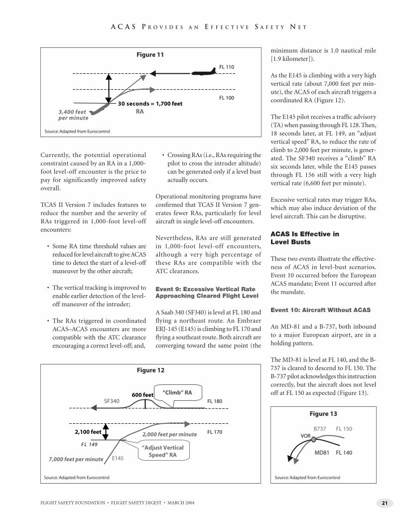
21FLIGHT SAFETY FOUNDATION • FLIGHT SAFETY DIGEST • MARCH 2004
A C A S P R O V I D E S A N E F F E C T I V E S A F E T Y N E T
Currently, the potential operational constraint caused by an RA in a 1,000-foot level-off encounter is the price to pay for significantly improved safety overall.
TCAS II Version 7 includes features to reduce the number and the severity of RAs triggered in 1,000-foot level-off encounters:
• Some RA time threshold values are reduced for level aircraft to give ACAS time to detect the start of a level-off maneuver by the other aircraft;
• The vertical tracking is improved to enable earlier detection of the level-off maneuver of the intruder;
• The RAs triggered in coordinated ACAS–ACAS encounters are more compatible with the ATC clearance encouraging a correct level-off; and,
• Crossing RAs (i.e., RAs requiring the pilot to cross the intruder altitude) can be generated only if a level bust actually occurs.
Operational monitoring programs have confi rmed that TCAS II Version 7 gen-erates fewer RAs, particularly for level aircraft in single level-off encounters.
Nevertheless, RAs are still generated in 1,000-foot level-off encounters, although a very high percentage of these RAs are compatible with the ATC clearances.
Event 9: Excessive Vertical Rate Approaching Cleared Flight Level
A Saab 340 (SF340) is level at FL 180 and flying a northeast route. An Embraer ERJ-145 (E145) is climbing to FL 170 and fl ying a southeast route. Both aircraft are converging toward the same point (the
minimum distance is 1.0 nautical mile [1.9 kilometer]).
As the E145 is climbing with a very high vertical rate (about 7,000 feet per min-ute), the ACAS of each aircraft triggers a coordinated RA (Figure 12).
The E145 pilot receives a traffi c advisory (TA) when passing through FL 128. Then, 18 seconds later, at FL 149, an “adjust vertical speed” RA, to reduce the rate of climb to 2,000 feet per minute, is gener-ated. The SF340 receives a “climb” RA six seconds later, while the E145 passes through FL 156 still with a very high vertical rate (6,600 feet per minute).
Excessive vertical rates may trigger RAs, which may also induce deviation of the level aircraft. This can be disruptive.
ACAS Is Effective in Level Busts
These two events illustrate the effective-ness of ACAS in level-bust scenarios. Event 10 occurred before the European ACAS mandate; Event 11 occurred after the mandate.
Event 10: Aircraft Without ACAS
An MD-81 and a B-737, both inbound to a major European airport, are in a holding pattern.
The MD-81 is level at FL 140, and the B-737 is cleared to descend to FL 150. The B-737 pilot acknowledges this instruction correctly, but the aircraft does not level off at FL 150 as expected (Figure 13).
FL 100
FL 110
3,400 feetper minute
30 seconds = 1,700 feetRA
Figure 11
FL 170
FL 180SF340
E1457,000 feet per minute
2,000 feet per minute2,100 feet
F L 149
600 feet “Climb” RA
“Adjust VerticalSpeed” RA
Figure 12
MD81 FL 140
B737 FL 150VOR
Figure 13
Source: Adapted from Eurocontrol
Source: Adapted from Eurocontrol Source: Adapted from Eurocontrol
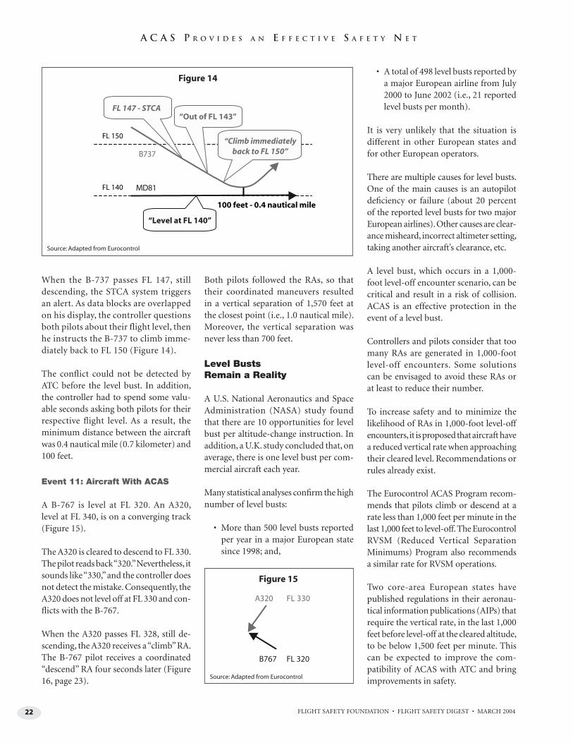
22 FLIGHT SAFETY FOUNDATION • FLIGHT SAFETY DIGEST • MARCH 2004
A C A S P R O V I D E S A N E F F E C T I V E S A F E T Y N E T
When the B-737 passes FL 147, still descending, the STCA system triggers an alert. As data blocks are overlapped on his display, the controller questions both pilots about their flight level, then he instructs the B-737 to climb imme-diately back to FL 150 (Figure 14).
The confl ict could not be detected by ATC before the level bust. In addition, the controller had to spend some valu-able seconds asking both pilots for their respective fl ight level. As a result, the minimum distance between the aircraft was 0.4 nautical mile (0.7 kilometer) and 100 feet.
Event 11: Aircraft With ACAS
A B-767 is level at FL 320. An A320, level at FL 340, is on a converging track (Figure 15).
The A320 is cleared to descend to FL 330. The pilot reads back “320.” Nevertheless, it sounds like “330,” and the controller does not detect the mistake. Consequently, the A320 does not level off at FL 330 and con-fl icts with the B-767.
When the A320 passes FL 328, still de-scending, the A320 receives a “climb” RA. The B-767 pilot receives a coordinated “descend” RA four seconds later (Figure 16, page 23).
Both pilots followed the RAs, so that their coordinated maneuvers resulted in a vertical separation of 1,570 feet at the closest point (i.e., 1.0 nautical mile). Moreover, the vertical separation was never less than 700 feet.
Level Busts Remain a Reality
A U.S. National Aeronautics and Space Administration (NASA) study found that there are 10 opportunities for level bust per altitude-change instruction. In addition, a U.K. study concluded that, on average, there is one level bust per com-mercial aircraft each year.
Many statistical analyses confi rm the high number of level busts:
• More than 500 level busts reported per year in a major European state since 1998; and,
• A total of 498 level busts reported by a major European airline from July 2000 to June 2002 (i.e., 21 reported level busts per month).
It is very unlikely that the situation is different in other European states and for other European operators.
There are multiple causes for level busts. One of the main causes is an autopilot defi ciency or failure (about 20 percent of the reported level busts for two major European airlines). Other causes are clear-ance misheard, incorrect altimeter setting, taking another aircraft’s clearance, etc.
A level bust, which occurs in a 1,000-foot level-off encounter scenario, can be critical and result in a risk of collision. ACAS is an effective protection in the event of a level bust.
Controllers and pilots consider that too many RAs are generated in 1,000-foot level-off encounters. Some solutions can be envisaged to avoid these RAs or at least to reduce their number.
To increase safety and to minimize the likelihood of RAs in 1,000-foot level-off encounters, it is proposed that aircraft have a reduced vertical rate when approaching their cleared level. Recommendations or rules already exist.
The Eurocontrol ACAS Program recom-mends that pilots climb or descend at a rate less than 1,000 feet per minute in the last 1,000 feet to level-off. The Eurocontrol RVSM (Reduced Vertical Separation Minimums) Program also recommends a similar rate for RVSM operations.
Two core-area European states have published regulations in their aeronau-tical information publications (AIPs) that require the vertical rate, in the last 1,000 feet before level-off at the cleared altitude, to be below 1,500 feet per minute. This can be expected to improve the com-patibility of ACAS with ATC and bring improvements in safety.
FL 140
FL 150
MD81
B737
100 feet - 0.4 nautical mile
“Out of FL 143”FL 147 - STCA
“Climb immediatelyback to FL 150”
“Level at FL 140”
Figure 14
B767 FL 320
A320 FL 330
Figure 15
Source: Adapted from Eurocontrol
Source: Adapted from Eurocontrol
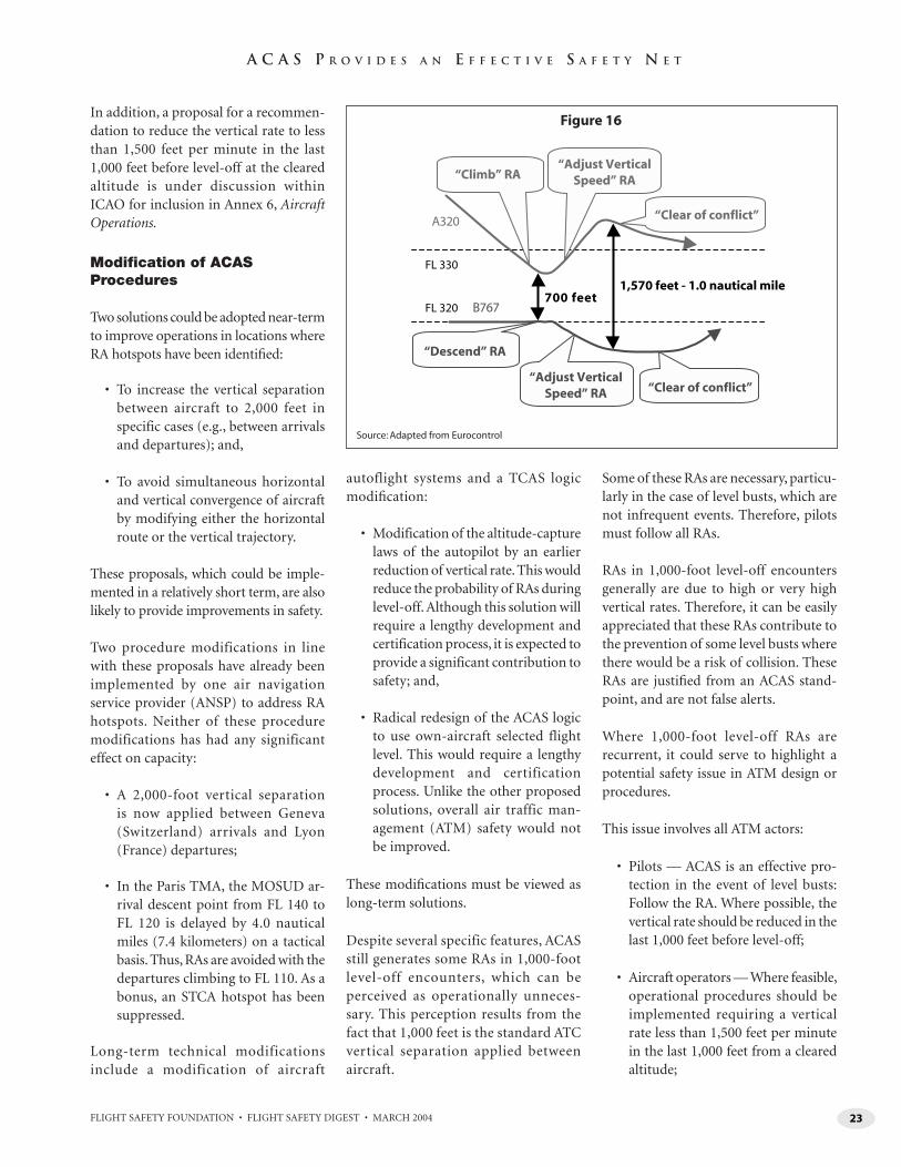
23FLIGHT SAFETY FOUNDATION • FLIGHT SAFETY DIGEST • MARCH 2004
A C A S P R O V I D E S A N E F F E C T I V E S A F E T Y N E T
In addition, a proposal for a recommen-dation to reduce the vertical rate to less than 1,500 feet per minute in the last 1,000 feet before level-off at the cleared altitude is under discussion within ICAO for inclusion in Annex 6, Aircraft Operations.
Modifi cation of ACAS Procedures
Two solutions could be adopted near-term to improve operations in locations where RA hotspots have been identifi ed:
• To increase the vertical separation between aircraft to 2,000 feet in specific cases (e.g., between arrivals and departures); and,
• To avoid simultaneous horizontal and vertical convergence of aircraft by modifying either the horizontal route or the vertical trajectory.
These proposals, which could be imple-mented in a relatively short term, are also likely to provide improvements in safety.
Two procedure modifications in line with these proposals have already been implemented by one air navigation service provider (ANSP) to address RA hotspots. Neither of these procedure modifications has had any significant effect on capacity:
• A 2,000-foot vertical separation is now applied between Geneva (Switzerland) arrivals and Lyon (France) departures;
• In the Paris TMA, the MOSUD ar-rival descent point from FL 140 to FL 120 is delayed by 4.0 nautical miles (7.4 kilometers) on a tactical basis. Thus, RAs are avoided with the departures climbing to FL 110. As a bonus, an STCA hotspot has been suppressed.
Long-term technical modifications include a modification of aircraft
autoflight systems and a TCAS logic modifi cation:
• Modification of the altitude-capture laws of the autopilot by an earlier reduction of vertical rate. This would reduce the probability of RAs during level-off. Although this solution will require a lengthy development and certification process, it is expected to provide a significant contribution to safety; and,
• Radical redesign of the ACAS logic to use own-aircraft selected flight level. This would require a lengthy development and certification process. Unlike the other proposed solutions, overall air traffic man-agement (ATM) safety would not be improved.
These modifi cations must be viewed as long-term solutions.
Despite several specific features, ACAS still generates some RAs in 1,000-foot level-off encounters, which can be perceived as operationally unneces-sary. This perception results from the fact that 1,000 feet is the standard ATC vertical separation applied between aircraft.
Some of these RAs are necessary, particu-larly in the case of level busts, which are not infrequent events. Therefore, pilots must follow all RAs.
RAs in 1,000-foot level-off encounters generally are due to high or very high vertical rates. Therefore, it can be easily appreciated that these RAs contribute to the prevention of some level busts where there would be a risk of collision. These RAs are justifi ed from an ACAS stand-point, and are not false alerts.
Where 1,000-foot level-off RAs are recurrent, it could serve to highlight a potential safety issue in ATM design or procedures.
This issue involves all ATM actors:
• Pilots — ACAS is an effective pro-tection in the event of level busts: Follow the RA. Where possible, the vertical rate should be reduced in the last 1,000 feet before level-off;
• Aircraft operators — Where feasible, operational procedures should be implemented requiring a vertical rate less than 1,500 feet per minute in the last 1,000 feet from a cleared altitude;
FL 320
FL 330
A320
B767700 feet
1,570 feet - 1.0 nautical mile
“Climb” RA“Adjust Vertical
Speed” RA
“Adjust VerticalSpeed” RA
“Clear of conflict”
“Clear of conflict”
“Descend” RA
Figure 16
Source: Adapted from Eurocontrol
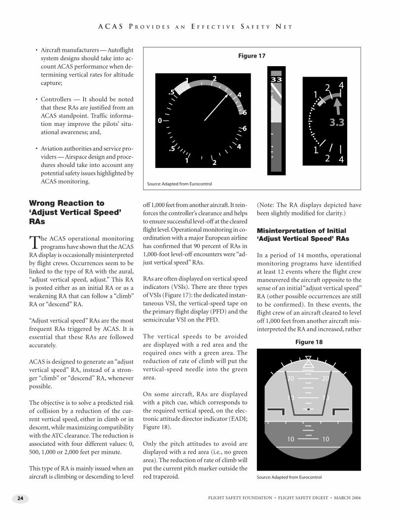
24 FLIGHT SAFETY FOUNDATION • FLIGHT SAFETY DIGEST • MARCH 2004
A C A S P R O V I D E S A N E F F E C T I V E S A F E T Y N E T
• Aircraft manufacturers — Autoflight system designs should take into ac-count ACAS performance when de-termining vertical rates for altitude capture;
• Controllers — It should be noted that these RAs are justified from an ACAS standpoint. Traffic informa-tion may improve the pilots’ situ-ational awareness; and,
• Aviation authorities and service pro-viders — Airspace design and proce-dures should take into account any potential safety issues highlighted by ACAS monitoring.
Wrong Reaction to ‘Adjust Vertical Speed’ RAs
The ACAS operational monitoring programs have shown that the ACAS
RA display is occasionally misinterpreted by fl ight crews. Occurrences seem to be linked to the type of RA with the aural, “adjust vertical speed, adjust.” This RA is posted either as an initial RA or as a weakening RA that can follow a “climb” RA or “descend” RA.
“Adjust vertical speed” RAs are the most frequent RAs triggered by ACAS. It is essential that these RAs are followed accurately.
ACAS is designed to generate an “adjust vertical speed” RA, instead of a stron-ger “climb” or “descend” RA, whenever possible.
The objective is to solve a predicted risk of collision by a reduction of the cur-rent vertical speed, either in climb or in descent, while maximizing compatibility with the ATC clearance. The reduction is associated with four different values: 0, 500, 1,000 or 2,000 feet per minute.
This type of RA is mainly issued when an aircraft is climbing or descending to level
off 1,000 feet from another aircraft. It rein-forces the controller’s clearance and helps to ensure successful level-off at the cleared fl ight level. Operational monitoring in co-ordination with a major European airline has confi rmed that 90 percent of RAs in 1,000-foot level-off encounters were “ad-just vertical speed” RAs.
RAs are often displayed on vertical speed indicators (VSIs). There are three types of VSIs (Figure 17): the dedicated instan-taneous VSI, the vertical-speed tape on the primary fl ight display (PFD) and the semicircular VSI on the PFD.
The vertical speeds to be avoided are displayed with a red area and the required ones with a green area. The reduction of rate of climb will put the vertical-speed needle into the green area.
On some aircraft, RAs are displayed with a pitch cue, which corresponds to the required vertical speed, on the elec-tronic attitude director indicator (EADI; Figure 18).
Only the pitch attitudes to avoid are displayed with a red area (i.e., no green area). The reduction of rate of climb will put the current pitch marker outside the red trapezoid.
(Note: The RA displays depicted have been slightly modifi ed for clarity.)
Misinterpretation of Initial ‘Adjust Vertical Speed’ RAs
In a period of 14 months, operational monitoring programs have identifi ed at least 12 events where the fl ight crew maneuvered the aircraft opposite to the sense of an initial “adjust vertical speed” RA (other possible occurrences are still to be confi rmed). In these events, the fl ight crew of an aircraft cleared to level off 1,000 feet from another aircraft mis-interpreted the RA and increased, rather
421
421
3.3
33
0
.5
.5
1 2
4
6
6
4
21
Figure 17
20 20
10 10
10 10
Figure 18
Source: Adapted from Eurocontrol
Source: Adapted from Eurocontrol
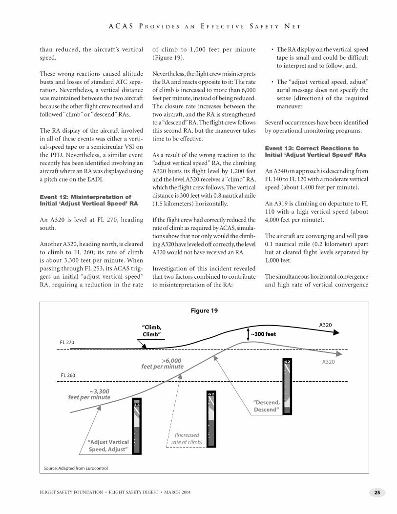
25FLIGHT SAFETY FOUNDATION • FLIGHT SAFETY DIGEST • MARCH 2004
A C A S P R O V I D E S A N E F F E C T I V E S A F E T Y N E T
than reduced, the aircraft’s vertical speed.
These wrong reactions caused altitude busts and losses of standard ATC sepa-ration. Nevertheless, a vertical distance was maintained between the two aircraft because the other fl ight crew received and followed “climb” or “descend” RAs.
The RA display of the aircraft involved in all of these events was either a verti-cal-speed tape or a semicircular VSI on the PFD. Nevertheless, a similar event recently has been identifi ed involving an aircraft where an RA was displayed using a pitch cue on the EADI.
Event 12: Misinterpretation of Initial ‘Adjust Vertical Speed’ RA
An A320 is level at FL 270, heading south.
Another A320, heading north, is cleared to climb to FL 260; its rate of climb is about 3,300 feet per minute. When passing through FL 253, its ACAS trig-gers an initial “adjust vertical speed” RA, requiring a reduction in the rate
of climb to 1,000 feet per minute (Figure 19).
Nevertheless, the fl ight crew misinterprets the RA and reacts opposite to it: The rate of climb is increased to more than 6,000 feet per minute, instead of being reduced. The closure rate increases between the two aircraft, and the RA is strengthened to a “descend” RA. The fl ight crew follows this second RA, but the maneuver takes time to be effective.
As a result of the wrong reaction to the “adjust vertical speed” RA, the climbing A320 busts its fl ight level by 1,200 feet and the level A320 receives a “climb” RA, which the fl ight crew follows. The vertical distance is 300 feet with 0.8 nautical mile (1.5 kilometers) horizontally.
If the fl ight crew had correctly reduced the rate of climb as required by ACAS, simula-tions show that not only would the climb-ing A320 have leveled off correctly, the level A320 would not have received an RA.
Investigation of this incident revealed that two factors combined to contribute to misinterpretation of the RA:
• The RA display on the vertical-speed tape is small and could be difficult to interpret and to follow; and,
• The “adjust vertical speed, adjust” aural message does not specify the sense (direction) of the required maneuver.
Several occurrences have been identifi ed by operational monitoring programs.
Event 13: Correct Reactions to Initial ‘Adjust Vertical Speed’ RAs
An A340 on approach is descending from FL 140 to FL 120 with a moderate vertical speed (about 1,400 feet per minute).
An A319 is climbing on departure to FL 110 with a high vertical speed (about 4,000 feet per minute).
The aircraft are converging and will pass 0.1 nautical mile (0.2 kilometer) apart but at cleared fl ight levels separated by 1,000 feet.
The simultaneous horizontal convergence and high rate of vertical convergence
“Adjust VerticalSpeed, Adjust”
“Descend,Descend”
A320
A320
“Climb,Climb”
FL 270
FL 260
~300 feet00
~3,300 feet per minute
>6,000 feet per minute
(Increasedrate of climb)
33
62
62
Figure 19
Source: Adapted from Eurocontrol
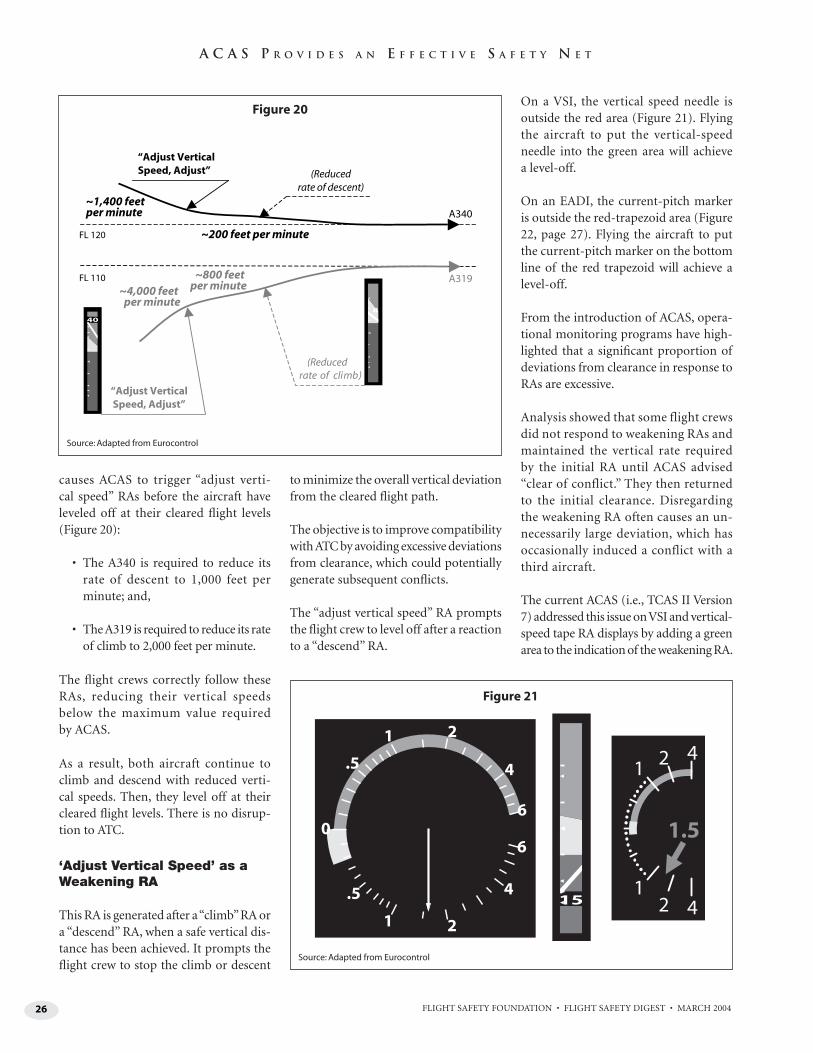
26 FLIGHT SAFETY FOUNDATION • FLIGHT SAFETY DIGEST • MARCH 2004
A C A S P R O V I D E S A N E F F E C T I V E S A F E T Y N E T
causes ACAS to trigger “adjust verti-cal speed” RAs before the aircraft have leveled off at their cleared fl ight levels (Figure 20):
• The A340 is required to reduce its rate of descent to 1,000 feet per minute; and,
• The A319 is required to reduce its rate of climb to 2,000 feet per minute.
The fl ight crews correctly follow these RAs, reducing their vertical speeds below the maximum value required by ACAS.
As a result, both aircraft continue to climb and descend with reduced verti-cal speeds. Then, they level off at their cleared fl ight levels. There is no disrup-tion to ATC.
‘Adjust Vertical Speed’ as a Weakening RA
This RA is generated after a “climb” RA or a “descend” RA, when a safe vertical dis-tance has been achieved. It prompts the fl ight crew to stop the climb or descent
to minimize the overall vertical deviation from the cleared fl ight path.
The objective is to improve compatibility with ATC by avoiding excessive deviations from clearance, which could potentially generate subsequent confl icts.
The “adjust vertical speed” RA prompts the fl ight crew to level off after a reaction to a “descend” RA.
On a VSI, the vertical speed needle is outside the red area (Figure 21). Flying the aircraft to put the vertical-speed needle into the green area will achieve a level-off.
On an EADI, the current-pitch marker is outside the red-trapezoid area (Figure 22, page 27). Flying the aircraft to put the current-pitch marker on the bottom line of the red trapezoid will achieve a level-off.
From the introduction of ACAS, opera-tional monitoring programs have high-lighted that a signifi cant proportion of deviations from clearance in response to RAs are excessive.
Analysis showed that some flight crews did not respond to weakening RAs and maintained the vertical rate required by the initial RA until ACAS advised “clear of conflict.” They then returned to the initial clearance. Disregarding the weakening RA often causes an un-necessarily large deviation, which has occasionally induced a conflict with a third aircraft.
The current ACAS (i.e., TCAS II Version 7) addressed this issue on VSI and vertical-speed tape RA displays by adding a green area to the indication of the weakening RA.
Figure 20
Figure 21
421
421
1.5
15
0
.5
.5
1 2
4
6
6
4
21
Source: Adapted from Eurocontrol
Source: Adapted from Eurocontrol
“Adjust VerticalSpeed, Adjust”
A340
A319
FL 120
FL 110
~4,000 feetper minute
(Reducedrate of climb)
“Adjust VerticalSpeed, Adjust” (Reduced
rate of descent)~1,400 feetper minute
~800 feetper minute
~200 feet per minute
40
8
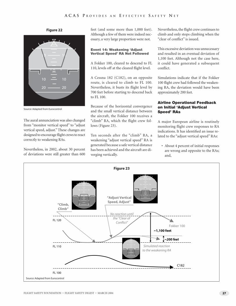
27FLIGHT SAFETY FOUNDATION • FLIGHT SAFETY DIGEST • MARCH 2004
A C A S P R O V I D E S A N E F F E C T I V E S A F E T Y N E T
The aural annunciation was also changed from “monitor vertical speed” to “adjust vertical speed, adjust.” These changes are designed to encourage fl ight crews to react correctly to weakening RAs.
Nevertheless, in 2002, about 30 percent of deviations were still greater than 600
feet (and some more than 1,000 feet). Although a few of them were indeed nec-essary, a very large proportion were not.
Event 14: Weakening ‘Adjust Vertical Speed’ RA Not Followed
A Fokker 100, cleared to descend to FL 110, levels off at the cleared fl ight level.
A Cessna 182 (C182), on an opposite route, is cleared to climb to FL 100. Nevertheless, it busts its fl ight level by 700 feet before starting to descend back to FL 100.
Because of the horizontal convergence and the small vertical distance between the aircraft, the Fokker 100 receives a “climb” RA, which the fl ight crew fol-lows (Figure 23).
Ten seconds after the “climb” RA, a weakening “adjust vertical speed” RA is generated because a safe vertical distance has been achieved and the aircraft are di-verging vertically.
Nevertheless, the fl ight crew continues to climb and only stops climbing when the “clear of confl ict” is issued.
This excessive deviation was unnecessary and resulted in an eventual deviation of 1,100 feet. Although not the case here, it could have generated a subsequent confl ict.
Simulations indicate that if the Fokker 100 fl ight crew had followed the weaken-ing RA, the deviation would have been approximately 200 feet.
Airline Operational Feedback on Initial ‘Adjust Vertical Speed’ RAs
A major European airline is routinely monitoring fl ight crew responses to RA indications. It has identifi ed an issue re-lated to the “adjust vertical speed” RAs:
• About 4 percent of initial responses are wrong and opposite to the RAs; and,
20 20
10 10
10 10
Figure 22
Figure 23
FL 100
C182
Fokker 100
FL 110
FL 120
Simulated reactionto the weakening RA
~1,100 feet
~200 feet
No reaction untilthe “Clear of
Conflict”
“Climb,Climb”
“Adjust VerticalSpeed, Adjust”
20 20
10 10
10 10
20 20
10 10
10 10
20 20
10 10
10 10
Source: Adapted from Eurocontrol
Source: Adapted from Eurocontrol
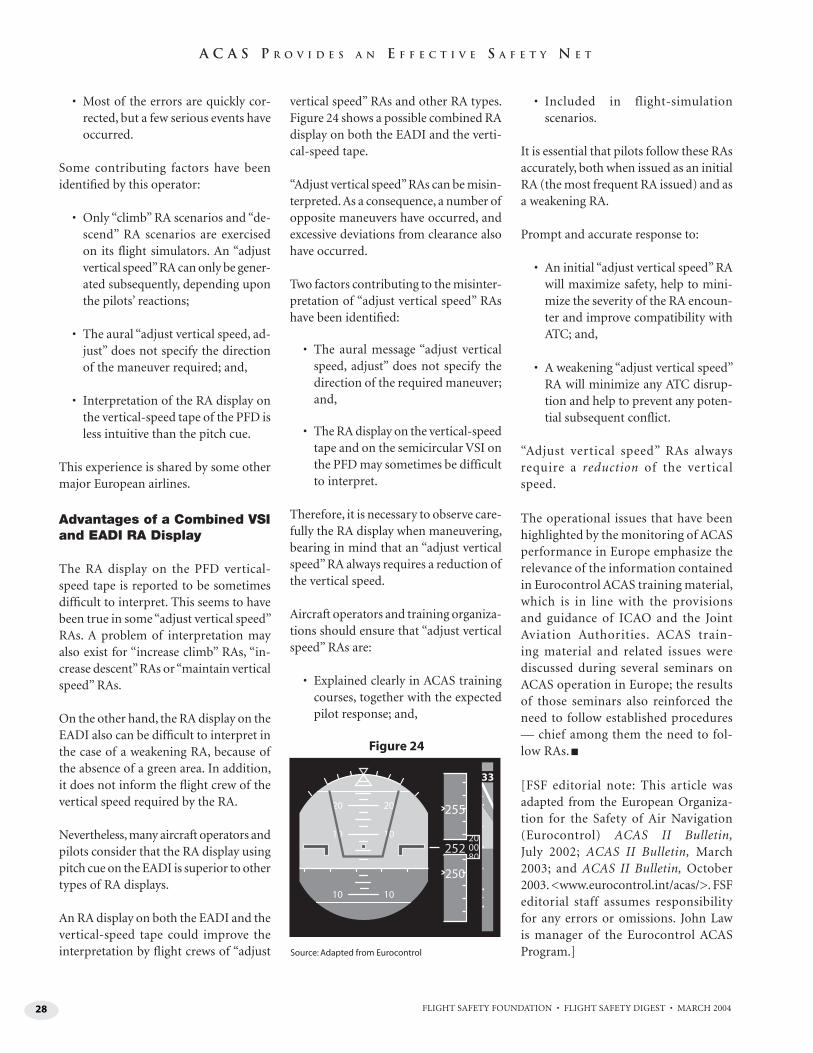
28 FLIGHT SAFETY FOUNDATION • FLIGHT SAFETY DIGEST • MARCH 2004
A C A S P R O V I D E S A N E F F E C T I V E S A F E T Y N E T
• Most of the errors are quickly cor-rected, but a few serious events have occurred.
Some contributing factors have been identifi ed by this operator:
• Only “climb” RA scenarios and “de-scend” RA scenarios are exercised on its flight simulators. An “adjust vertical speed” RA can only be gener-ated subsequently, depending upon the pilots’ reactions;
• The aural “adjust vertical speed, ad-just” does not specify the direction of the maneuver required; and,
• Interpretation of the RA display on the vertical-speed tape of the PFD is less intuitive than the pitch cue.
This experience is shared by some other major European airlines.
Advantages of a Combined VSI and EADI RA Display
The RA display on the PFD vertical-speed tape is reported to be sometimes diffi cult to interpret. This seems to have been true in some “adjust vertical speed” RAs. A problem of interpretation may also exist for “increase climb” RAs, “in-crease descent” RAs or “maintain vertical speed” RAs.
On the other hand, the RA display on the EADI also can be diffi cult to interpret in the case of a weakening RA, because of the absence of a green area. In addition, it does not inform the fl ight crew of the vertical speed required by the RA.
Nevertheless, many aircraft operators and pilots consider that the RA display using pitch cue on the EADI is superior to other types of RA displays.
An RA display on both the EADI and the vertical-speed tape could improve the interpretation by fl ight crews of “adjust
vertical speed” RAs and other RA types. Figure 24 shows a possible combined RA display on both the EADI and the verti-cal-speed tape.
“Adjust vertical speed” RAs can be misin-terpreted. As a consequence, a number of opposite maneuvers have occurred, and excessive deviations from clearance also have occurred.
Two factors contributing to the misinter-pretation of “adjust vertical speed” RAs have been identifi ed:
• The aural message “adjust vertical speed, adjust” does not specify the direction of the required maneuver; and,
• The RA display on the vertical-speed tape and on the semicircular VSI on the PFD may sometimes be difficult to interpret.
Therefore, it is necessary to observe care-fully the RA display when maneuvering, bearing in mind that an “adjust vertical speed” RA always requires a reduction of the vertical speed.
Aircraft operators and training organiza-tions should ensure that “adjust vertical speed” RAs are:
• Explained clearly in ACAS training courses, together with the expected pilot response; and,
• Included in flight-simulation scenarios.
It is essential that pilots follow these RAs accurately, both when issued as an initial RA (the most frequent RA issued) and as a weakening RA.
Prompt and accurate response to:
• An initial “adjust vertical speed” RA will maximize safety, help to mini-mize the severity of the RA encoun-ter and improve compatibility with ATC; and,
• A weakening “adjust vertical speed” RA will minimize any ATC disrup-tion and help to prevent any poten-tial subsequent conflict.
“Adjust vertical speed” RAs always require a reduction of the vertical speed.
The operational issues that have been highlighted by the monitoring of ACAS performance in Europe emphasize the relevance of the information contained in Eurocontrol ACAS training material, which is in line with the provisions and guidance of ICAO and the Joint Aviation Authorities. ACAS train-ing material and related issues were discussed during several seminars on ACAS operation in Europe; the results of those seminars also reinforced the need to follow established procedures — chief among them the need to fol-low RAs. ■
[FSF editorial note: This article was adapted from the European Organiza-tion for the Safety of Air Navigation (Eurocontrol) ACAS II Bulletin, July 2002; ACAS II Bulletin, March 2003; and ACAS II Bulletin, October 2003. <www.eurocontrol.int/acas/>. FSF editorial staff assumes responsibility for any errors or omissions. John Law is manager of the Eurocontrol ACAS Program.]
20
33
255
250
252
20
10 10
10 10
Figure 24
Source: Adapted from Eurocontrol
FLIGHT SAFETY FOUNDATION • FLIGHT SAFETY DIGEST • MARCH 2004 29
Australian High-capacity Aircraft Sector Reduces Accident Rate in 2002
The preliminary 2002 data showed a rate of 0.3 accidents per 100,000 departures,
the lowest of the non-zero rates reported since 1993. No fatal accidents occurred in
this sector during the 1992–2001 period.
— FSF EDITORIAL STAFF
Reported Australian aircraft occurrences (accidents and incidents combined) in-creased 50 percent from fi scal
year 1996–1997 to 2002–2003 (Table 1, page 30), said a report by the Australian Transport Safety Bureau (ATSB). The number of accidents showed a decreas-ing trend, and the number of incidents showed an increasing trend. Although in-cidents increased steadily during a 10-year period, the recent sharp increase can be attributed to the 1998 introduction of electronic safety incident reports from Air Services Australia, increased report-ing by airlines because of “a growing safety culture within the airlines” and ATSB’s own more comprehen-sive incident-recording policy, which includes “all reported bird strikes instead
of only those signifi cantly damaging air-craft,” the report said.
A decrease in occurrences in 2002–2003 — compared with the peak 2000–2001 fi scal year — was attributed to possible factors including “statistical variation, the cessation of operations by Ansett Australia and a decline in tourism and aviation activ-ity” involving the effects of terrorist attacks in the United States on Sept. 11, 2001, and in Bali, Indonesia, on Oct. 12, 2002, and the effect of the severe acute respiratory syndrome (SARS) virus, the report said.
“High-capacity aircraft operations con-tinue to be the safest, with extremely low accident rates [Table 2, page 30],” the report said. “While caution needs to be exercised because of the small
AVIATION STATISTICS
“High-capacity
aircraft operations
continue to be
the safest.”
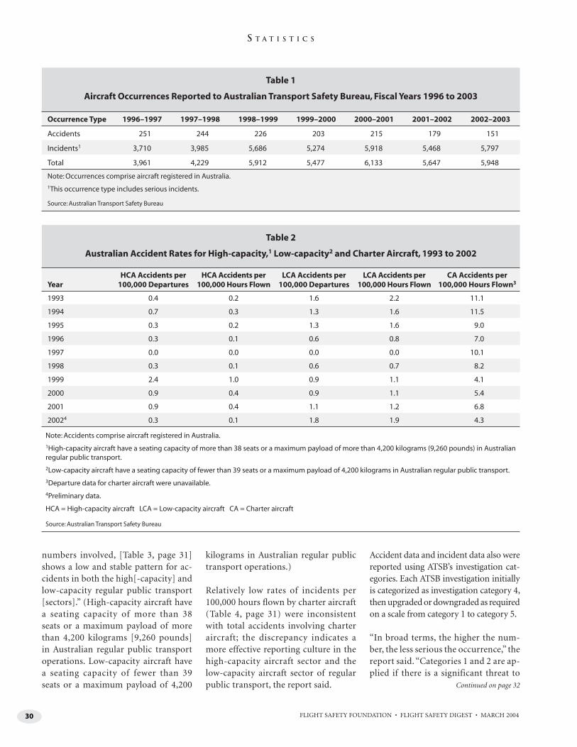
FLIGHT SAFETY FOUNDATION • FLIGHT SAFETY DIGEST • MARCH 200430
S T A T I S T I C S
Table 1
Aircraft Occurrences Reported to Australian Transport Safety Bureau, Fiscal Years 1996 to 2003
Occurrence Type 1996–1997 1997–1998 1998–1999 1999–2000 2000–2001 2001–2002 2002–2003
Accidents 251 244 226 203 215 179 151
Incidents1 3,710 3,985 5,686 5,274 5,918 5,468 5,797
Total 3,961 4,229 5,912 5,477 6,133 5,647 5,948
Note: Occurrences comprise aircraft registered in Australia.
1This occurrence type includes serious incidents.
Source: Australian Transport Safety Bureau
Table 2
Australian Accident Rates for High-capacity,1 Low-capacity2 and Charter Aircraft, 1993 to 2002
YearHCA Accidents per
100,000 DeparturesHCA Accidents per
100,000 Hours FlownLCA Accidents per
100,000 DeparturesLCA Accidents per
100,000 Hours FlownCA Accidents per
100,000 Hours Flown3
1993 0.4 0.2 1.6 2.2 11.1
1994 0.7 0.3 1.3 1.6 11.5
1995 0.3 0.2 1.3 1.6 9.0
1996 0.3 0.1 0.6 0.8 7.0
1997 0.0 0.0 0.0 0.0 10.1
1998 0.3 0.1 0.6 0.7 8.2
1999 2.4 1.0 0.9 1.1 4.1
2000 0.9 0.4 0.9 1.1 5.4
2001 0.9 0.4 1.1 1.2 6.8
20024 0.3 0.1 1.8 1.9 4.3
Note: Accidents comprise aircraft registered in Australia.
1High-capacity aircraft have a seating capacity of more than 38 seats or a maximum payload of more than 4,200 kilograms (9,260 pounds) in Australian regular public transport.
2Low-capacity aircraft have a seating capacity of fewer than 39 seats or a maximum payload of 4,200 kilograms in Australian regular public transport.
3Departure data for charter aircraft were unavailable.
4Preliminary data.
HCA = High-capacity aircraft LCA = Low-capacity aircraft CA = Charter aircraft
Source: Australian Transport Safety Bureau
numbers involved, [Table 3, page 31] shows a low and stable pattern for ac-cidents in both the high[-capacity] and low-capacity regular public transport [sectors].” (High-capacity aircraft have a seating capacity of more than 38 seats or a maximum payload of more than 4,200 kilograms [9,260 pounds] in Australian regular public transport operations. Low-capacity aircraft have a seating capacity of fewer than 39 seats or a maximum payload of 4,200
kilograms in Australian regular public transport operations.)
Relatively low rates of incidents per 100,000 hours fl own by charter aircraft (Table 4, page 31) were inconsistent with total accidents involving charter aircraft; the discrepancy indicates a more effective reporting culture in the high-capacity aircraft sector and the low-capacity aircraft sector of regular public transport, the report said.
Accident data and incident data also were reported using ATSB’s investigation cat-egories. Each ATSB investigation initially is categorized as investigation category 4, then upgraded or downgraded as required on a scale from category 1 to category 5.
“In broad terms, the higher the num-ber, the less serious the occurrence,” the report said. “Categories 1 and 2 are ap-plied if there is a significant threat to
Continued on page 32
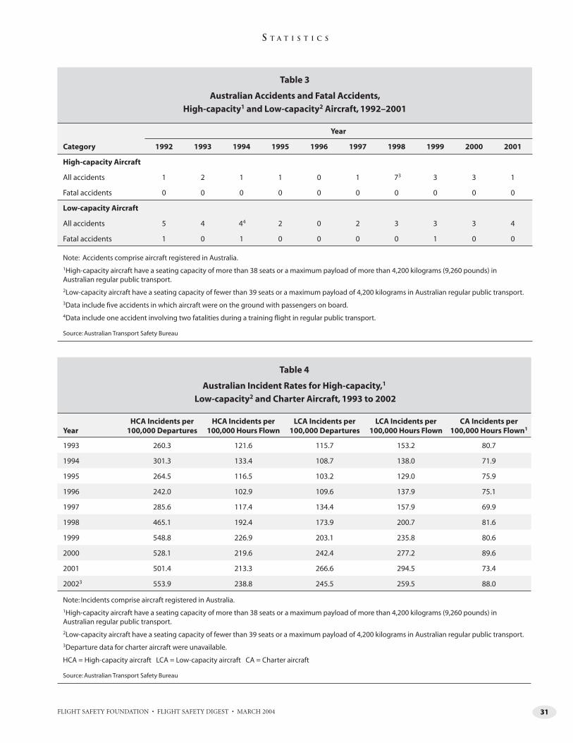
FLIGHT SAFETY FOUNDATION • FLIGHT SAFETY DIGEST • MARCH 2004 31
S T A T I S T I C S
Table 3
Australian Accidents and Fatal Accidents,
High-capacity1 and Low-capacity2 Aircraft, 1992–2001
Year
Category 1992 1993 1994 1995 1996 1997 1998 1999 2000 2001
High-capacity Aircraft
All accidents 1 2 1 1 0 1 73 3 3 1
Fatal accidents 0 0 0 0 0 0 0 0 0 0
Low-capacity Aircraft
All accidents 5 4 44 2 0 2 3 3 3 4
Fatal accidents 1 0 1 0 0 0 0 1 0 0
Note: Accidents comprise aircraft registered in Australia.
1High-capacity aircraft have a seating capacity of more than 38 seats or a maximum payload of more than 4,200 kilograms (9,260 pounds) in Australian regular public transport.
2Low-capacity aircraft have a seating capacity of fewer than 39 seats or a maximum payload of 4,200 kilograms in Australian regular public transport.
3Data include fi ve accidents in which aircraft were on the ground with passengers on board.
4Data include one accident involving two fatalities during a training fl ight in regular public transport.
Source: Australian Transport Safety Bureau
Table 4
Australian Incident Rates for High-capacity,1
Low-capacity2 and Charter Aircraft, 1993 to 2002
YearHCA Incidents per
100,000 DeparturesHCA Incidents per
100,000 Hours FlownLCA Incidents per
100,000 DeparturesLCA Incidents per
100,000 Hours FlownCA Incidents per
100,000 Hours Flown1
1993 260.3 121.6 115.7 153.2 80.7
1994 301.3 133.4 108.7 138.0 71.9
1995 264.5 116.5 103.2 129.0 75.9
1996 242.0 102.9 109.6 137.9 75.1
1997 285.6 117.4 134.4 157.9 69.9
1998 465.1 192.4 173.9 200.7 81.6
1999 548.8 226.9 203.1 235.8 80.6
2000 528.1 219.6 242.4 277.2 89.6
2001 501.4 213.3 266.6 294.5 73.4
20023 553.9 238.8 245.5 259.5 88.0
Note: Incidents comprise aircraft registered in Australia.
1High-capacity aircraft have a seating capacity of more than 38 seats or a maximum payload of more than 4,200 kilograms (9,260 pounds) in Australian regular public transport.
2Low-capacity aircraft have a seating capacity of fewer than 39 seats or a maximum payload of 4,200 kilograms in Australian regular public transport.
3Departure data for charter aircraft were unavailable.
HCA = High-capacity aircraft LCA = Low-capacity aircraft CA = Charter aircraft
Source: Australian Transport Safety Bureau
FLIGHT SAFETY FOUNDATION • FLIGHT SAFETY DIGEST • MARCH 200432
S T A T I S T I C S
public safety, while category 4 is normally used for occurrences where the facts do not indicate a serious safety deficiency or where the defi-ciency is well-known. Occurrence categories have varied over time, with the balance between categories 4 and 5 in particular influenced by resource availability and investigator workload. For the period 1993 to 2002, most high- capacity, low-capacity and charter accidents [were] cat-egory 4.”
ATSB’s investigation category 1 comprises the following:
• An accident involving one or more high-capacity air transport (scheduled and nonscheduled) passenger aircraft with fa-talities;
• An accident involving one or more high-capacity air transport (scheduled and nonscheduled) passenger aircraft without fatalities where there was a significant risk of fatalities or serious injuries, a substantial commitment of investigative resources is likely to significantly mitigate future high-capacity air transport accidents, and fund-ing is available for an investigation under this category; or,
• A serious incident involving one or more high-capacity air transport (scheduled and nonscheduled) passenger aircraft where there was a significant risk of fatalities or serious injuries and a substantial commitment of in-vestigative resources is likely to significantly mitigate future high-capacity air transport (scheduled and nonscheduled) accidents, and funding is available for an investigation under this category.
From 1998 through 2002, no accidents or incidents were assigned to category 1.
Category 2 comprises the following:
• An accident involving one or more high-capacity air transport cargo aircraft with fatalities and serious injuries;
• An accident involving one or more high- capacity air transport cargo aircraft with-out fatalities and serious injuries where
there was a significant risk of fatalities or serious injuries, a substantial commit-ment of investigative resources is likely to significantly mitigate future high-capacity air transport cargo aircraft accidents, and funding is available for an investigation under this category;
• An accident involving one or more low- capacity air transport (scheduled) passenger aircraft with a significant number of fatalities (for example, more than five fatalities) and serious injuries;
• An accident involving one or more low- capacity air transport (scheduled) passenger aircraft without fatalities or with a relatively low level of fatalities (for example, fewer than five fatalities) and serious injuries where there was a significant risk of more fatalities or serious injuries, a substantial commit-ment of investigative resources is likely to significantly mitigate future low-capacity air transport (scheduled) accidents, and fund-ing is available for an investigation under this category;
• A serious incident involving one or more low-capacity air transport (scheduled) passenger aircraft where there was a sig-nificant risk of multiple fatalities (for example, more than five fatalities) and serious injuries, a substantial commit-ment of investigative resources is likely to significantly mitigate future low-capacity air transport (scheduled) accidents, and funding is available for an investigation under this category; or,
• An accident involving one or more low-capacity charter (nonscheduled) aircraft with fare-paying passengers and multiple fatalities and serious injuries (for example, more than five fatalities), a substantial com-mitment of investigative resources is likely to significantly mitigate future low-capac-ity air transport (scheduled) and charter (non-scheduled) accidents, and funding is available for an investigation under this category.
From 1998 through 2002, the following were reported in category 2:
STATS
FLIGHT SAFETY FOUNDATION • FLIGHT SAFETY DIGEST • MARCH 2004 33
S T A T I S T I C S
• One high-capacity aircraft accident in 1999;
• One low-capacity aircraft accident in 2000;
• One charter aircraft accident in 1998, one in 2000 and one in 2001;
• No high-capacity aircraft incidents;
• One low-capacity aircraft incident in 1998, one in 2000 and one in 2002; and,
• No charter aircraft incidents.
Category 3 comprises the following:
• An accident involving one or more low- capacity air transport passenger (scheduled) or charter (nonscheduled) aircraft with fare-paying passengers with fatalities and/or serious injuries not classified as a category 2 investigation;
• An accident involving air transport cargo operations with fatalities;
• An accident involving one or more training aircraft with fatalities, investigation is likely to significantly mitigate future accidents, and funding is available for an investigation under this category;
• An accident without fatalities involving one or more high-capacity air transport aircraft or low-capacity air transport aircraft not classi-fied as a category 1 or category 2 investigation, investigation is likely to significantly mitigate future accidents, and funding is available for an investigation under this category;
• An accident involving one or more general aviation aircraft (other than sport aviation) with fatalities where investigation is likely to significantly mitigate future accidents and funding is available for an investigation under this category;
• An accident involving one or more charter aircraft or other general aviation aircraft, a significant risk of fatalities or serious injuries and a substantial commitment of
investigative resources would significantly mitigate accidents, and funding is available for an investigation in this category;
• A serious incident involving one or more high-capacity air transport aircraft or low-capacity air transport aircraft not clas-sified as a category 1 or category 2 investiga-tion, investigation is likely to significantly mitigate future accidents, and funding is available for an investigation under this category; or,
• A serious incident involving one or more air transport cargo, charter or training aircraft where investigation is likely to significantly mitigate future accidents and funding is avail-able for an investigation under this category.
From 1998 through 2002, the following were reported in category 3:
• Two high-capacity aircraft accidents in 1999 and one in 2000;
• One low-capacity aircraft accident in 1999;
• Three charter aircraft accidents in 1998, two in 1999, three in 2000, two in 2001 and two in 2002;
• Two high-capacity aircraft incidents in 1998, one in 1999, four in 2000, 10 in 2001 and two in 2002;
• Two low-capacity aircraft incidents in 1998, two in 1999, four in 2000 and four in 2001; and,
• One charter aircraft incident in 1998, three in 1999 and one in 2001.
Category 4 comprises the following:
• An accident involving a non-Australian- registered aircraft covered by Article 26 of the Chicago Convention that is not being investi-gated as category 1, category 2 or category 3;
• An accident involving aircraft (other than sport aviation) with fatalities where available resources and future safety considerations do not allow for a more detailed investigation;
STATS
FLIGHT SAFETY FOUNDATION • FLIGHT SAFETY DIGEST • MARCH 200434
S T A T I S T I C S
STATS
• An accident or serious incident involv-ing Australian-designed and Australian- manufactured aircraft types on the Australian Register with international safety implications not being investigated as category 1, category 2 or category 3;
• An accident or serious incident involving one or more high-capacity air transport aircraft or low-capacity air transport aircraft not being investigated as category 1, category 2 or category 3 and funding is available for an investigation;
• An accident involving one or more charter aircraft or general aviation aircraft without fatalities where a limited commitment of investigative resources could significantly mitigate future aviation accidents and fund-ing is available for an investigation; or,
• A serious incident involving one or more non-air-transport aircraft where a limited commitment of investigative resources could significantly mitigate future accidents and funding is available for an investigation.
From 1998 through 2002, the following were reported in category 4:
• One high-capacity aircraft accident in 1998, three in 1999, two in 2000 and one in 2001;
• Two low-capacity aircraft accidents in 1998, two in 1999, two in 2000 and two in 2001;
• Thirty-seven charter aircraft accidents in 1998, 19 in 1999, seven in 2000, seven in 2001 and four in 2002;
• A total of 580 high-capacity aircraft incidents in 1998, 551 in 1999, 76 in 2000, 33 in 2001 and 26 in 2002;
• A total of 313 low-capacity aircraft incidents in 1998, 289 in 1999, 37 in 2000, 15 in 2001 and six in 2002; and,
• A total of 187 charter aircraft incidents in 1998, 173 in 1999, 16 in 2000, seven in 2001 and four in 2002.
Category 5 comprises the following:
• An accident (including an accident with fa-talities) or serious incident involving a sport aviation aircraft unless a non-Australian-registered aircraft is involved and is required to be investigated under Article 26 of the Chicago Convention;
• An accident involving aircraft without fatali-ties where the potential safety lessons do not, after initial review, justify the commitment of investigative resources within available funds (basic incident data will be filed for statistical purposes); or,
• A serious incident or incident involving aircraft where the potential safety lessons do not, after initial review, justify the com-mitment of investigative resources within available funds (basic incident data will be filed for statistical purposes).
From 1998 through 2002, the following were reported in category 5:
• One high-capacity aircraft accident in 1999, two in 2001 and one in 2002;
• One low-capacity aircraft accident in 2001 and four in 2002;
• Fifteen charter aircraft accidents in 2000, 22 in 2001 and 13 in 2002;
• A total of 781 high-capacity aircraft incidents in 1998, 1,058 in 1999, 1,627 in 2000, 1,661 in 2001 and 1,690 in 2002;
• A total of 257 low-capacity aircraft incidents in 1998, 382 in 1999, 750 in 2000, 715 in 2001 and 534 in 2002; and,
• A total of 218 charter aircraft incidents in 1998, 233 in 1999, 414 in 2000, 336 in 2001 and 385 in 2002. ■
[This article, except where specifi cally noted, is based on Annual Review 2003 by the Australian Transport Safety Bureau (ATSB) and on defi ni-tions of terms published on the ATSB Internet site, <www.atsb.gov.au>.]
FLIGHT SAFETY FOUNDATION • FLIGHT SAFETY DIGEST • MARCH 2004 35
Report Cites Turbulence, Convection Factors as Prominent in FARs Part 121 Weather-related Accidents
Reports
National Aviation Weather Program, Mid-course Assessment: Accident Reduction Trends Confi rm Value of Coordinated R&D Programs. U.S. Offi ce of the Federal Coordinator for Meteorological Services and Supporting Research (OFCM). August 2003. FCM-R20-2003. 80 pp. Figures, tables, appendixes, images, references. Available from OFCM.*
Midway through a 10-year U.S. Na-tional Aviation Weather Program,
designed to reduce fatal weather-related aviation accidents, statistics show the fol-lowing trends, according to the OFCM report:
• U.S. Federal Aviation Regulations (FARs) Part 121 aircraft experienced only two weather-related fatal acci-dents in the 1994–2001 period, pre-venting trend analysis. Nevertheless, there was a downward trend in all weather-related Part 121 accidents;
• Part 91 aircraft showed strong down-ward trends in numbers of fatal ac-cidents, and the 80-percent reduction goal appears attainable by 2006; and,
• Overall, Part 135 aircraft are not expe-riencing the same risk reductions as Part 91 aircraft and Part 121 aircraft, mainly because of factors unique to Part 135 aircraft, such as range of operations and types of services.
In 1997, recommendations from the U.S. White House Commission on Aviation Safety and Security called for an 80-percent reduction in fatal aviation ac-cidents from all causes as a 10-year national goal. The U.S. Federal Aviation Administration (FAA) adopted the 80-percent reduction goal and initiated the “Safer Skies” plan. In parallel, the U.S. National Aviation Weather Program Council recommended an 80-percent reduction in weather-related accidents as the overall measure of success for its coordinated research-and-development (R&D) programs.
To assess progress toward reducing weather-related risks to aviation safety, this report examined accident data ob-tained from FAA and the U.S. National Transportation Safety Board and com-pared accidents in which weather was identifi ed as a factor to accidents with non-weather-related factors. The report contains data tables comparing accidents (fatal and nonfatal) by types of weather hazards, meteorological conditions, frequency per 100,000 fl ight hours and program goals. Using 1996 accident levels as the benchmark, the report identifi es trends in weather-related accidents for operations conducted under Part 91, Part 121 and Part 135 and offers recom-mendations for continuing initiatives.
The report says, concerning Part 121 weather-related accidents, “The most notable feature in the data is the promi-nence of … turbulence and convection hazards, in the citations each year. … These turbulence and convection haz-ards dominate the weather conditions that continue to contribute to accidents
PUBLICATIONS RECEIVED AT FSF JERRY LEDERER
AVIATION SAFETY LIBRARY
Weather-related-accident reduction in FARs Part 91 operations appears to be
on target for meeting 10-year program goals.
— FSF LIBRARY STAFF
FLIGHT SAFETY FOUNDATION • FLIGHT SAFETY DIGEST • MARCH 200436
R E F E R E N C E S
— albeit not usually fatal ones — for the major air carriers.”
Trends do not indicate that accident-reduction goals for Part 135 aircraft will be met in the categories of restricted visibility and ceiling haz-ards, precipitation (nonicing) hazards and icing conditions, the report said. Trends in other Part 135 weather-related accident categories are am-biguous. “The aircraft category regulated under [FARs] Part 135 displays weather-related accident-rate trends distinct from both the Part 91 and Part 121 categories,” says the report. “Aviation-weather initiatives and programs should consider special factors relevant to this category, rather than as-suming it is partly like the large commercial air carriers and partly like general aviation.”
What Aircrews Should Know About Their Occupational Exposure to Ionizing Radiation. Friedberg, Wallace; Copeland, Kyle. U.S. Federal Aviation Administration (FAA) Offi ce of Aerospace Medicine (OAM). DOT/FAA/AM-03/16. October 2003. 11 pp. Tables, references. Available on the Internet at <www.cami.jccbi.gov> or from NTIS.**
Flight crews are occupationally exposed to ionizing radiation, which causes subatomic
particles to interact with an atom, resulting in the loss of an electron or even breakage of the nucleus. When such changes occur in body tissues, health issues can arise, principally a small increase in the lifetime risk of fatal cancer.
Exposure of fl ight crews to potentially excessive ionizing radiation results mainly from galactic cosmic radiation. The report defines ionizing radiation and identifi es ionizing radiation doses from natural sources within the United States. Health risks to crewmembers and their children irradiated in utero and the risk of genetic defects in future generations are explained.
The report suggests ways that fl ight crewmembers may determine their exposure using computer software provided by FAA or dosing tables based on altitude, fl ight time and total trip time.
The Effects of Laser Illumination on Operational and Visual Performance of Pilots Conducting Terminal Operations. Nakagawara, Van B.; Montgomery, Ron W.;
Dillard, Archie; McLin, Leon; Connor, C. William. U.S. Federal Aviation Administration (FAA) Offi ce of Aerospace Medicine (OAM). DOT/FAA/AM-03/12. August 2003. 13 pp. Figures, references. Available on the Internet at <www.cami.jccbi.gov> or from NTIS.**
In response to hundreds of reported incidents involving the illumination of fl ight crewmem-
bers by laser light, the FAA revised FAA Order 7400.2, Part 6, Miscellaneous Procedures: Outdoor Laser Operations to protect fl ight crewmembers and passengers from biological tissue damage and temporary visual impairment resulting from exposure to visible laser beams in designated zones of navigable airspace.
To validate FAA recommendations, 38 multien-gine-rated civilian and military pilots participated in tests to evaluate their performance during simu-lated approach and departure maneuvers in the critical fl ight zone (CFZ), one of the designated zones of navigable airspace defi ned in relation to an airport reference point, while exposed to laser radiation.
Results validated the FAA recommendations for limits on laser light exposure in the CFZ. Pilots reported a “slight” effect on their operational and visual performance in the CFZ. Altitude of aircraft above the ground and distance from the landing area in the CFZ provided adequate time for vi-sual recovery after laser exposure. Pilots noted that familiarization with the aircraft, instrument training and familiarization with effects of laser exposure appeared to improve the ability to toler-ate laser events.
The report says, “Laser illumination at a higher level of exposure resulted in an unacceptable number of visual and operational problems.”
Civil and Military Aircraft Accident Procedures for Police Offi cers and Emergency Services Personnel. Australian Transport Safety Bureau (ATSB) and the Directorate of Flying Safety–Australian Defence Force (DFS-ADF). August 2003. Edition 2. 40 pp. Tables, photographs, checklist. Available from DFS-ADF.***
This booklet provides guidance to civil aviation authorities, military and emergency person-
nel, and others who may be the fi rst to arrive at
FLIGHT SAFETY FOUNDATION • FLIGHT SAFETY DIGEST • MARCH 2004 37
R E F E R E N C E S
an aircraft-accident site. Essential procedural steps are outlined and address notifi cation; site coordination and security; protection of wreck-age; recording eyewitness accounts; rescue and recovery; dangerous materials; and site hazards. A checklist of reminders for emergency-services personnel is included.
This edition supersedes Edition 1, dated November 2002, making minor corrections and refl ecting the new Transport Safety Investigation Act 2003.
Books
100 Years of Civil Aviation. International Systems and Communications Limited (ISC); International Civil Aviation Organization (ICAO). London, U.K.: ISC, 2003. 312 pp. Photographs.
Articles about the first 100 years of civil aviation emphasize contributions made
by individuals and organizations in developing aircraft, systems and safety. Articles reflect upon visions held by aviation pioneers and aviation organizations; contributions of science and technology; socio-economic and cultural influ-ences upon the aviation industry; standards and recommended practices; and programs initiated by ICAO and its members. Challenges to the aviation industries of today and tomorrow also are discussed.
The publication includes a chapter on the late Jerome F. “Jerry” Lederer, “Mr. Aviation Safety,” founder of Flight Safety Foundation.
The Plane Truth: Airline Crashes, the Media, and Transportation Policy. Cobb, Roger W.; Primo, David M. Washington, D.C., U.S.: Brookings Institution Press, 2003. 217 pp. Figures, tables, appendix, notes, index.
The book says that an airline accident brings two competing human responses into play.
The fi rst response, reinforced by media images of aircraft debris and human casualties, is fear and the question, “Is fl ying safe?” The second response, acceptance of the relative safety of fl ying, is based on logic. “The media stress the fi rst response, while offi cials focus on the second,” says the book. “Fear,
however, usually trumps logic as a prime reaction to disaster situations.”
Using several signifi cant U.S. aircraft accidents as examples, the book describes how media report-ing infl uenced reactions and investigations by government and industry, and, ultimately, airline transportation policy. The appendix lists accidents by date, indicating airline name, cause of accident and resulting policy changes.
[The Brookings Institution is a private, nonprofi t organization devoted to research, education and publication on issues of U.S. domestic and foreign policy.]
Encyclopedia of Technical Aviation. Bristow, Gary V. New York, New York, U.S.: McGraw-Hill, 2003. 463 pp. Figures.
Aviation terminology is as varied and diverse as the aviation topics it describes — aerodynam-
ics, human factors, engines, meteorology, satellite navigation, rules of the air, instrument fl ight rules and aircraft performance. The text is presented in dictionary-style, A-Z format, starting with “absolute ceiling” and ending with “zero-fuel weight.”
The book is written as a reference resource for pilots in all stages of their careers, from pilots in training to early-career pilots to experienced pilots desiring to expand or refresh knowledge of the ever-changing, technologically advancing aviation world.
Regulatory Materials
Airworthiness Approval of Global Navigation Satellite System (GNSS) Equipment. U.S. Federal Aviation Administration (FAA) Advisory Circular (AC) 20-138A. Dec. 22, 2003. 68 pp. Tables, appendixes. Available from GPO.****
This AC provides guidance for obtaining air-worthiness approval of GNSS equipment,
specifi cally the following:
• GNSS sensors, including those incorporating wide area augmentation system (WAAS), lo-cal area augmentation system (LAAS) or the Russian Global Navigation Satellite System (GLONASS); and,
FLIGHT SAFETY FOUNDATION • FLIGHT SAFETY DIGEST • MARCH 200438
R E F E R E N C E S
• GNSS stand-alone navigation equipment for en route, terminal or approach operations (in-cluding Category I precision approaches).
The document summarizes the approval process, covers GNSS as an aid to visual fl ight rules navigation and instrument fl ight rules navigation, and addresses equipment performance and function. Samples of quick reference guides as training aids and samples of supplements to fl ight manuals are included.
[This AC cancels AC 20-138, Airworthiness Approval of Global Positioning System (GPS) Navigation Equipment for Use as a VFR and IFR Supplemental Navigation System, dated May 25,
1994.]
Parts 91, 121, 125, and 135 Flightcrew Procedures During Taxi Operations. U.S. Federal Aviation Administration (FAA) Advisory Circular (AC) 120-74A. Sept. 26, 2003. 44 pp. Appendixes. Available from GPO.****
Getting to and from a runway has become in-creasingly complex because of the increased
numbers of aircraft and adherence to scheduled departure times, variously combined with weather, aircraft type, language usage and time of day, the AC says. The AC focuses on activities occurring within the cockpit (planning, communicating and coordinating), rather than actual control of the aircraft, to reduce the potential for runway incidents and accidents.
The AC’s intended use is development and im-plementation of standard operating procedures (SOPs) for safe aircraft operations during taxiing and is directed to persons operating aircraft under U.S. Federal Aviation Regulations (FARs) Part 91, Part 121, Part 125 and Part 135 with two or more pilots on the fl ight deck. The AC recommends that these guidelines become an integral part of all SOPs, fl ight operations manuals and formal fl ight crew training programs.
Guidelines are grouped into six major categories: planning; situational awareness; use of written taxi
instructions; intra-fl ight deck and cockpit verbal coordination; air traffi c control and fl ight crew communication; and taxiing. Examples of SOPs appear in the appendixes.
[This AC cancels AC 120-74, Parts 121, 125, and 135 Flightcrew Procedures During Taxi Operations, dated June 18, 2001.]
Turbine Engine Continued Rotation and Rotor Locking. U.S. Federal Aviation Administration (FAA) Advisory Circular (AC) 33.74/92-1A. July 23, 2003. 6 pp. Available from GPO.****
The safety objective of this AC is to ensure that airplane and helicopter turbine engines that
continue to rotate after shutdown will not create hazards to the aircraft. This AC provides guidance to engine manufacturers, modifi ers, foreign regu-latory authorities, FAA engine-type-certifi cation engineers and their designers regarding failure conditions, fi re hazards, fatigue assessment and rotor-locking devices.
[This AC revises AC 33.74/92, Turbine Engine Continued Rotation and Rotor Locking, dated Feb. 14, 1997.] ■
Sources
* Offi ce of the Federal Coordinator for Meteorological Services and Supporting Research (OFCM)8455 Colesville RoadSilver Spring, MD 20910 U.S.Internet: <http://www.ofcm.gov>
** National Technical Information Service (NTIS)5285 Port Royal RoadSpringfi eld, VA 22161 U.S.Internet: <http://www.ntis.gov>
*** John Crawley, EditorDFS-ADFCampbell Park Offi ces CP4-1-102Department of DefenceCanberra, ACT 2600 Australia
**** Superintendent of DocumentsU.S. Government Printing Offi ce (GPO)Washington, DC 20402 U.S.Internet: <http://www.access.gpo.gov>
LIBRARY
FLIGHT SAFETY FOUNDATION • FLIGHT SAFETY DIGEST • MARCH 2004 39
Error in Airspeed CalculationsCited in B-747 Tail Strike
The following information provides an awareness of problems through which such occurrences may be prevented in the future. Accident/incident briefs are
based on preliminary information from govern-ment agencies, aviation organizations, press infor-mation and other sources. This information may not be entirely accurate.
Rotation Speed Was 33 Knots Too Slow, Report SaysBoeing 747-400. Substantial damage. No injuries.
As the captain rotated the airplane for takeoff from an airport in New Zealand on a fl ight to
Singapore, the tail struck the runway and scraped the surface for about 490 meters (1,608 feet) until the airplane became airborne.
An investigation found that the tail strike occurred because the airplane’s rotation speed was 33 knots less than the 163 knots required for the airplane’s weight. The accident report said that the rotation speed had been calculated incorrectly, based on an
airplane weight that was 100 metric tons (220,460 pounds) less than the actual weight of the accident airplane.
“A takeoff weight transcription error, which remained undetected, led to the miscalculation of the takeoff data, which in turn resulted in a low-thrust setting and excessively slow takeoff reference speeds,” the report said. “The system defenses did not ensure [that] the errors were detected, and the airplane fl ight management sys-tem itself did not provide a fi nal defense against mismatched information being programmed into it.”
The report said that, during the takeoff, the air-plane had moved near the edge of the runway and the pilots had not responded correctly to a stall warning.
“The airplane takeoff performance was degraded by the inappropriately low thrust and reference speed settings, which compromised the ability of the airplane to cope with an engine failure and hence compromised the safety of the airplane and its occupants,” the report said.
ACCIDENT/INCIDENT BRIEFS
The accident report by the New Zealand Transport Accident Investigation Commission
said that the airplane’s rotation speed had been calculated using an aircraft weight that
was 100 metric tons (220,460 pounds) less than the actual takeoff weight.
— FSF EDITORIAL STAFF
AIR
CA
RR
IER
FLIGHT SAFETY FOUNDATION • FLIGHT SAFETY DIGEST • MARCH 200440
A C C I D E N T S / I N C I D E N T S
Faulty Slat Confi guration Cited in Rejected TakeoffMcDonnell Douglas DC-10. Minor damage. No injuries.
Visual meteorological conditions prevailed for the morning takeoff from an airport in
the United States. The airplane was taxied from the gate to the departure runway — a distance of about six miles (10 kilometers). During accelera-tion, the takeoff warning horn sounded and the crew rejected the takeoff.
As the airplane decelerated, air traffi c control said that smoke — and then fi re — was coming from the left-main landing gear. The airplane was stopped on the runway, the fl ight crew conducted appropriate checklists, and the seven people in the airplane disembarked using an evacuation slide. Aircraft rescue and fi re fi ghting equipment were sent to the scene.
A preliminary investigation indicated that the takeoff warning horn had sounded because of “a confi guration problem with the inboard/outboard slats,” the accident report said. “An inspection of the center-inboard slat-drive mechanism revealed the inboard slat-drive keel-beam support-rod end had popped off the bushing.”
Airplane Door Damaged During Pushback
Airbus A330. Minor damage. No injuries.
In preparation for departure on a domestic fl ight in Australia, the two forward-left aircraft doors had
been closed, the airbridges had been retracted and the ground engineer had been told that departure was imminent. Because aircraft weight-and-balance data differed from what had been expected, passenger seats were reassigned; an airbridge servicing door was returned to the airplane, and a cabin-crew customer service manager reopened the door to allow ground-based service agents to board the air-craft to supervise re-seating. The door was opened without the permission of the captain — whose permission was required by the operator.
The ground engineer was not told that the airbridge had been returned to the door, “and clearance to open the door was not sought,” a report said.
The only indication to the fl ight crew that the door had been opened was the appearance of an amber light on the door symbol on the electronic cen-tralized aircraft monitoring system. Nevertheless, because the fl ight crew already had verifi ed that the doors were closed, there was no requirement to check the doors again before pushback began.
“The fl ight crew obtained clearance for pushback from air traffi c control, and the pushback from the terminal was commenced,” the report said. “As the aircraft moved rearwards, the opened door … impacted the airbridge. The door and airbridge were defl ected into the aircraft fuselage, causing signifi cant damage to the fuselage skin and associated structure. Damage to the airbridge was limited to surface scraping and associated paint loss.”
After the incident, the operator reviewed its pro-cedures for airbridge return and door opening and took steps to improve communication and coordination among those responsible for dis-patching aircraft.
Faulty Starter Generator Cited in EFIS FailuresSaab Aircraft SF 340B. No damage. No injuries.
The airplane was being fl own through Flight Level 180 (approximately 18,000 feet) after
departure from an airport in Australia when the fi rst offi cer’s two electronic fl ight information system (EFIS) screens, on the right side of the instrument panel, failed.
The crew conducted the EFIS “Failure/disturbances” checklist, and then the central-warning-panel ice-protection annunciator light and the cabin-pressure annunciator light illumi-nated. The crew began an emergency descent and declared pan pan, an urgent condition.
“During the descent, a number of other cock-pit warnings and cautions activated, and some aircraft systems failed,” the accident report said. “The crew became aware that the right DC [direct current] generation system was operating abnor-mally. Their attempts to rectify that situation were unsuccessful.”
AIR
TA
XI/
CO
MM
UT
ER
FLIGHT SAFETY FOUNDATION • FLIGHT SAFETY DIGEST • MARCH 2004 41
A C C I D E N T S / I N C I D E N T S
They diverted the airplane to an en route airport, where they conducted a landing.
The failure of the EFIS screens and the subsequent problems were “consistent with a right-system voltage drop from the rated 28 volts DC to below 18 volts,” the report said. “During the investiga-tion, it became apparent that in some Saab 340 aircraft, a starter generator could fail without tak-ing the generator off line and alerting the crew, resulting in low system voltage.”
The report said that the crew had overlooked a checklist item that required a check of generator voltage.
“Consequently, the crew did not recognize the developing low voltage condition that led to the cascading series of warnings, cautions and fail-ures,” the report said. “The bus tie relay, which was designed to automatically connect the two main electrical systems in the case of generator failure, did not operate. An optional generator control unit modifi cation to prevent unalerted low-volt-age conditions had not been incorporated.”
Fuel Starvation Prompts Engine Shutdown Over English ChannelPiper PA-34-220T Seneca III. No damage. No injuries.
The airplane was being flown on a public transport fl ight across the English Channel
from England to France when the right engine stopped producing power and ran roughly. Gauges indicated that the right fuel tank was empty, that fuel pressure for the right engine was zero and that the left fuel tank contained 10 gallons (38 liters) of fuel.
The captain shut down and feathered the right engine and diverted the airplane to a nearby air-port, where she conducted a landing. Maintenance checks determined that fuel starvation had caused the problem.
An investigation found that the day before the fl ight, the captain had calculated the amount of fuel required for the fl ight and that the fueling organization was asked to add about 26 gallons (100 liters) of fuel to the tanks.
“However, the fax machine at the refueling point had run out of toner,” the report said. “The fax request did not print, with the result that the refueling organization was unaware that the aircraft required refueling, and it was not refueled.”
When the captain conducted the prefl ight inspec-tion, she could not see fuel in the fuel tanks, “but given the reduced amount to be carried, she was not concerned.” The fuel gauges indicated less fuel in each fuel tank than she expected, but “she doubted the accuracy of light aircraft fuel gauges,” the report said.
After the incident, the operator reviewed company operating procedures for refueling and in-fl ight fuel management, the captain received additional training, and the refueling organization began in-dicating on the fuel-order form how much fuel was loaded into each fuel tank.
Skyvan Strikes Canal Bank During Emergency LandingShort Brothers SC.7 Skyvan. Substantial damage. Two fatalities, five serious injuries.
Visual meteorological conditions prevailed for the late morning takeoff of the charter
passenger and cargo airplane from an airport in Guyana. About one minute after takeoff, when the airplane was at 200 feet to 300 feet, the pilot declared an emergency and said that he intended to land the airplane in a sugar cane fi eld. During the landing, the airplane struck a canal bank near the fi eld.
A preliminary investigation revealed that the right engine was not developing power when the airplane struck the ground. The investigation was continuing.
Airplane Slides Across Icy Ramp Into Concrete Wall
Gates Learjet 35A. Substantial damage. No injuries.
Visual meteorological conditions prevailed for the landing at an airport in the United
CO
RP
OR
AT
E/B
US
INE
SS
FLIGHT SAFETY FOUNDATION • FLIGHT SAFETY DIGEST • MARCH 200442
A C C I D E N T S / I N C I D E N T S
States. After landing, the fl ight crew taxied the airplane off the runway without diffi culty, but as the airplane was turned onto the ramp, it slid on a layer of ice.
The brakes were ineffective, and the crew shut down the engines. Nevertheless, because of the downward slope of the ramp area and the wind, which was from 300 degrees at 16 knots, with gusts to 27 knots, the airplane accelerated on the ramp and struck a concrete retaining wall.
An inspection of the area about 90 minutes after the accident found that the layer of ice on the ramp was about one inch (2.5 centimeters) thick.
Tire Fails During TakeoffRockwell Commander 690A. Substantial damage. No injuries.
Visual meteorological conditions prevailed and an instrument fl ight rules fl ight plan was fi led
for the fl ight from an airport in the United States. During the takeoff roll, about 1,250 feet (381 me-ters) from the departure end of the runway, the left-main landing gear tire failed. The airplane veered off the runway to the left and stopped in a fi eld.
Landing Gear Fails to Retract, Collapses During LandingBeech Super King Air 200. Minor damage. No injuries.
After takeoff from an airport in England, the pilot conducted the usual after-takeoff
actions, including moving the landing-gear selector lever to retract the landing gear. After controllers in the air traffic control tower told him that the landing gear was extended, he ob-served that the selector handle was in the “UP” position and that the “gear unsafe” warning light was illuminated. A visual check confirmed that both main landing gears were extended.
The pilot said that he selected the landing-gear selector lever “DOWN” to recycle the landing gear; subsequently, he was unable to move the lever to the “UP” position. After flying the airplane past the airport control tower, con-trollers said that the landing gear appeared to
be extended, and the pilot decided to land the airplane.
“On landing, the aircraft rolled straight along the runway for a while before it veered to the left and stopped,” the accident report said. “Realizing that the landing gear had collapsed, the pilot shut down the engines, switched off the electrical master switch and activated the fuel fi rewall shutoff valves before evacuating the aircraft, together with the other occupants, through the main entry door.”
An examination of the airplane revealed that, al-though all three landing gears had collapsed, the nose landing gear had remained extended suffi ciently to keep the propellers from scraping the ground.
The report said that an electrical problem ap-parently prevented the landing gear from being completely retracted and that additional tests of the landing gear were planned.
The report also said that the pilot did not follow the correct procedures when he observed the “GEAR UNSAFE” warning light and the absence of three green lights that would have indicated that the landing gear was fully extended.
“The correct procedure when faced with this eventuality was to select the landing gear down again, and, if ‘three greens’ were not obtained, to isolate the landing gear [circuit breaker] before activating the emergency [landing-]gear exten-sion manual-crank mechanism, until they were obtained,” the report said.
Replica of Lindbergh’s Plane Destroyed at Air ShowRyan M1/M2 NYP. Destroyed. One fatality.
The airplane, a replica of the one in which Charles Lindbergh made the fi rst trans-Atlantic crossing in 1927, was being fl own in an air show in England. Soon after the pilot began a series of gentle ma-neuvers to display the airplane in fl ight, the right wing “suffered a major structural failure,” the ac-cident report said.
As the pilot conducted a level right turn, the right wing leading edge rolled backward and the right
OT
HE
R G
EN
ER
AL
AV
IAT
ION
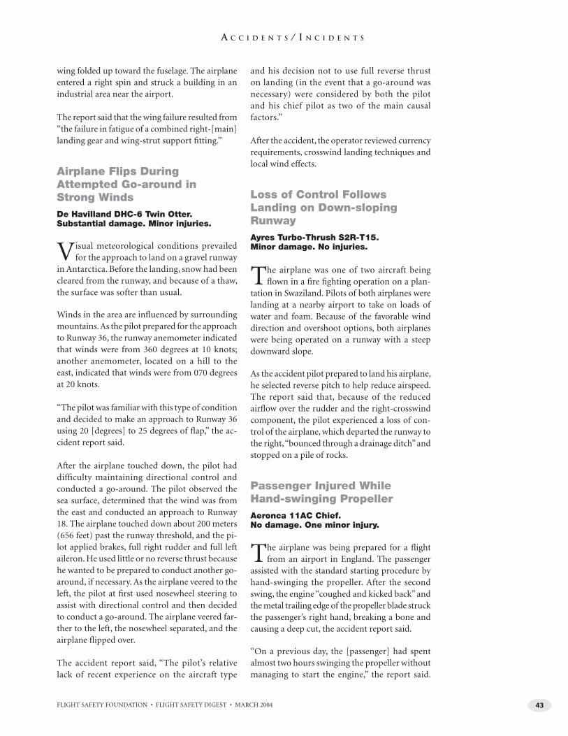
FLIGHT SAFETY FOUNDATION • FLIGHT SAFETY DIGEST • MARCH 2004 43
A C C I D E N T S / I N C I D E N T S
wing folded up toward the fuselage. The airplane entered a right spin and struck a building in an industrial area near the airport.
The report said that the wing failure resulted from “the failure in fatigue of a combined right-[main] landing gear and wing-strut support fi tting.”
Airplane Flips During Attempted Go-around in Strong WindsDe Havilland DHC-6 Twin Otter. Substantial damage. Minor injuries.
Visual meteorological conditions prevailed for the approach to land on a gravel runway
in Antarctica. Before the landing, snow had been cleared from the runway, and because of a thaw, the surface was softer than usual.
Winds in the area are infl uenced by surrounding mountains. As the pilot prepared for the approach to Runway 36, the runway anemometer indicated that winds were from 360 degrees at 10 knots; another anemometer, located on a hill to the east, indicated that winds were from 070 degrees at 20 knots.
“The pilot was familiar with this type of condition and decided to make an approach to Runway 36 using 20 [degrees] to 25 degrees of fl ap,” the ac-cident report said.
After the airplane touched down, the pilot had diffi culty maintaining directional control and conducted a go-around. The pilot observed the sea surface, determined that the wind was from the east and conducted an approach to Runway 18. The airplane touched down about 200 meters (656 feet) past the runway threshold, and the pi-lot applied brakes, full right rudder and full left aileron. He used little or no reverse thrust because he wanted to be prepared to conduct another go-around, if necessary. As the airplane veered to the left, the pilot at fi rst used nosewheel steering to assist with directional control and then decided to conduct a go-around. The airplane veered far-ther to the left, the nosewheel separated, and the airplane fl ipped over.
The accident report said, “The pilot’s relative lack of recent experience on the aircraft type
and his decision not to use full reverse thrust on landing (in the event that a go-around was necessary) were considered by both the pilot and his chief pilot as two of the main causal factors.”
After the accident, the operator reviewed currency requirements, crosswind landing techniques and local wind effects.
Loss of Control Follows Landing on Down-sloping RunwayAyres Turbo-Thrush S2R-T15. Minor damage. No injuries.
The airplane was one of two aircraft being fl own in a fi re fi ghting operation on a plan-
tation in Swaziland. Pilots of both airplanes were landing at a nearby airport to take on loads of water and foam. Because of the favorable wind direction and overshoot options, both airplanes were being operated on a runway with a steep downward slope.
As the accident pilot prepared to land his airplane, he selected reverse pitch to help reduce airspeed. The report said that, because of the reduced airfl ow over the rudder and the right-crosswind component, the pilot experienced a loss of con-trol of the airplane, which departed the runway to the right, “bounced through a drainage ditch” and stopped on a pile of rocks.
Passenger Injured While Hand-swinging PropellerAeronca 11AC Chief. No damage. One minor injury.
The airplane was being prepared for a fl ight from an airport in England. The passenger
assisted with the standard starting procedure by hand-swinging the propeller. After the second swing, the engine “coughed and kicked back” and the metal trailing edge of the propeller blade struck the passenger’s right hand, breaking a bone and causing a deep cut, the accident report said.
“On a previous day, the [passenger] had spent almost two hours swinging the propeller without managing to start the engine,” the report said.
FLIGHT SAFETY FOUNDATION • FLIGHT SAFETY DIGEST • MARCH 200444
A C C I D E N T S / I N C I D E N T S
“On this occasion, he swung the propeller with-out expecting the engine to fi re and was caught off guard when it did and the propeller kicked back.”
External Load Strikes, Severs Tail RotorHughes 369F. Substantial damage. No injuries.
Visual meteorological conditions prevailed for the late afternoon external-load operation in
the United States. The accident fl ight was the last fl ight of the day, and a load consisting of four lad-ders had been placed in a cargo net and attached to the helicopter’s long line.
After takeoff, as the helicopter accelerated, the pilot heard a bang and felt the helicopter pitch forward and roll left. The pilot conducted an autorotation and landed the helicopter in a riverbed.
A preliminary inspection revealed that one of the ladders had shifted during takeoff and had struck the tail rotor, which separated from the helicopter. The helicopter then struck terrain.
Helicopter Strikes Power Lines During Photographic FlightAerospatiale AS 350B. Minor damage. No injuries.
The helicopter was being flown on a photo-graphic flight in Scotland, with passengers
filming marine traffic on two bodies of water. As the pilot flew the helicopter in a descent to 200 feet above ground level, he conducted 1 1/4 turns to the right, then turned the helicopter left and observed power lines about 65 meters (213 feet) ahead. He applied aft cyclic to fly the helicopter over the power lines.
After the cameraman told him that the helicopter might have struck the wires, the pilot conducted a landing in a nearby fi eld, where examination of the helicopter showed that both tail-rotor blades and the lower vertical fi n had sustained wire-strike damage but were intact. One power line was severed.
After the accident, orange reflective devices were installed on the power lines to increase visibility.
The pilot said that the accident had occurred be-cause the fi lming operation had distracted him from his fl ight duties.
R22 Strikes Terrain During Mustering FlightRobinson R22. Substantial damage. Two fatalities.
The helicopter was one of two aircraft being fl own in a livestock-mustering operation
in Australia. After the pilot of the other heli-copter had heard no radio transmissions from the accident helicopter for about 15 minutes, he began a search for the helicopter and found the wreckage.
A preliminary investigation revealed that the helicopter had struck the ground heavily with little forward speed and that, at the time of im-pact, the main-rotor blades were rotating at low speed, the tail rotor was rotating at high speed, and the engine was operating at high power. The clutch shaft apparently failed before the impact.
A preliminary report said that the crashworthi-ness of the helicopter seats had been compro-mised by equipment that had been stored under the seats.
The investigation was continuing. ■
BR
IEFS
RO
TOR
CR
AFT
Now you have the safety tools to make a difference.
The Flight Safety Foundation is a comprehensive and practical resource on
compact disc to help you prevent the leading causes of fatalities in com mer cial aviation:
approach-and-landing ac ci dents (ALAs), including those involving controlled fl ight into ter rain (CFIT).
Put the FSF to work for you TODAY!• Separate lifesaving facts from fi ction among the data that confi rm ALAs and CFIT are the leading killers in avi a tion. Use FSF data-driven studies to reveal
eye-opening facts that are the nuts and bolts of the FSF ALAR Tool Kit.
• Volunteer specialists on FSF task forces from the international aviation industry studied the facts and de vel oped data-based con clu sions and recommendations to help pilots, air traffi c controllers and others prevent ALAs and CFIT. You can apply the results of this work — NOW!
• Review an industrywide consensus of best practices included in 34 FSF ALAR Briefi ng Notes. They provide practical in for ma tion that every pilot should know … but the FSF data confi rm that many pilots didn’t know — or ignored — this information. Use these benchmarks to build new standard operating pro ce dures and to im prove current ones.
• Related reading provides a library of more than 2,600 pages of factual information: sometimes chilling, but always useful. A versatile search engine will help you explore these pages and the other components of the FSF ALAR Tool Kit. (This collection of FSF publications would cost more than US$3,300 if purchased individually!)
• Print in six different languages the widely acclaimed FSF CFIT Checklist, which has been adapted by users for ev ery thing from checking routes to evaluating airports. This proven tool will enhance CFIT awareness in any fl ight department.
• Five ready-to-use slide presentations — with speakers’ notes — can help spread the safety message to a group, and enhance self-development. They cover ATC communication, fl ight op er a tions, CFIT prevention, ALA data and ATC/aircraft equipment. Customize them with your own notes.
• An approach and landing accident: It could happen to you! This 19-minute video can help enhance safety for every pilot — from student to professional — in the approach-and-landing environment.
• CFIT Awareness and Prevention: This 33-minute video includes a sobering description of ALAs/CFIT. And listening to the crews’ words and watching the accidents unfold with graphic depictions will imprint an un for get ta ble lesson for every pilot and every air traffi c controller who sees this video.
• Many more tools — including posters, the FSF Approach-and-landing Risk Awareness Tool and the FSF Approach-and-landing Risk Reduction Guide — are among the more than 590 mega bytes of in for ma tion in the FSF ALAR Tool Kit. An easy-to-navigate menu and book marks make the FSF ALAR Tool Kit user-friendly. Applications to view the slide pre sen ta tions, videos and pub li ca tions are included on the CD, which is designed to operate with Microsoft Windows or Apple Macintosh operating systems.
Order the FSF :Member price: US$40 Nonmember price: $160 Quantity discounts available!
Contact: Ellen Plaugher, special events and products manager, +1 (703) 739-6700, ext. 101.
Recommended System Requirements:
Windows®
• A Pentium®-based PC or compatible computer• At least 32MB of RAM• Windows 95/98/NT/ME/2000/XP system software• A Sound Blaster® or compatible sound card and speakers• DirectX® version 3.0 or later recommended
Mac® OS• A PowerPC processor-based Macintosh computer• At least 32MB of RAM• Mac OS 7.5.5 or later
Mac OS and Macintosh are trademarks of Apple Computer Inc. registered in the United States and other countries. Microsoft, Windows and DirectX are either registered trademarks or trade marks of Microsoft Corp. in the United States and/or other countries.
The FSF ALAR Tool Kit is not endorsed or sponsored by Apple Computer Inc. or Microsoft Corp.
Tool Kit
Flight Safety Foundation
Approach-and-landing Accident Reduction
Flight Safety FoundationAn independent, industry-sup port ed,
nonprofi t or ga ni za tion for the exchange of safety information
for more than 50 years
What can you do to improve aviation safe ty?Join Flight Safety Foundation.
• Receive 54 FSF regular periodicals including Accident Pre ven tion, Cabin Crew Safety and Flight Safety Digest that members may reproduce and use in their own publications.
• Receive discounts to attend well-es tab lished safety seminars for airline and corporateaviation managers.
• Receive member-only mailings of special reports on important safety issues such as controlled fl ight into terrain (CFIT), approach-and-landing accidents, human factors, and fatigue coun ter mea sures.
• Receive discounts on Safety Services including operational safety audits.
Your organization on the FSF membership list and Internet site presents your commitment to safety to the world.
Want more information about Flight Safety Foundation?
Contact Ann Hill, director, membership and developmentby e-mail: <hill@fl ightsafety.org> or by telephone: +1 (703) 739-6700, ext. 105.
Visit our Internet site at <www.fl ightsafety.org>.
We Encourage ReprintsArticles in this publication, in the interest of aviation safety, may be reprinted in whole or in part, but may not be offered for sale directly or indirectly, used commercially or distributed electronically on the Internet or on any other electronic media without the express written permission of Flight Safety Foundation’s director of publications. All uses must credit Flight Safety Foun da tion, Flight Safety Digest, the specifi c article(s) and the author(s). Please send two copies of the reprinted material to the director of pub li ca tions. These restrictions apply to all Flight Safety Foundation publications. Reprints must be ordered from the Foundation. For more information, contact the director of publications by telephone: +1 (703) 739-6700, ext. 116; or by e-mail: <rozelle@fl ightsafety.org>.
What’s Your Input?In keeping with the Foundation’s independent and non par ti san mission to disseminate objective safety in for ma tion, FSF publications solicit credible con tri bu tions that foster thought-provoking dis cus sion of aviation safety issues. If you have an article proposal, a completed manuscript or a technical paper that may be appropriate for Flight Safety Digest, please contact the director of publications. Rea son able care will be taken in handling a manu script, but Flight Safety Foundation assumes no responsibility for material submitted. The publications staff reserves the right to edit all pub lished sub mis sions. The Foundation buys all rights to manuscripts and payment is made to authors upon publication. Contact the Publications De part ment for more in for ma tion.
Flight Safety DigestCopyright © 2004 by Flight Safety Foundation Inc. All rights reserved. ISSN 1057-5588
Suggestions and opinions expressed in FSF pub li ca tions belong to the author(s) and are not nec es sar i ly endorsed by Flight Safety Foundation. This information is not intended to supersede operators’/manufacturers’ policies,
practices or requirements, or to supersede gov ern ment regulations.
Staff: Roger Rozelle, director of publications; Mark Lacagnina, senior editor; Wayne Rosenkrans, senior editor; Linda Werfelman, senior editor; Rick Darby, associate editor; Karen K. Ehrlich, web and print production coordinator; Ann L. Mullikin, pro duc tion designer;
Susan D. Reed, production specialist; and Patricia Setze, librarian, Jerry Lederer Aviation Safety Library
Subscriptions: One year subscription for 12 issues includes postage and handling: US$480. Include old and new addresses when requesting address change. • Attention: Ahlam Wahdan, membership services coordinator, Flight Safety Foun da tion, Suite 300, 601 Madison Street, Al ex an dria, VA 22314 U.S. • Tele phone: +1 (703) 739-6700 • Fax: +1 (703) 739-6708 • E-mail: <wahdan@fl ightsafety.org>