Embed Size (px)
Citation preview
APPROVEDChief DesignerAeroprakt Ltd.
Yuri V. Yakovlev Version : 18/07/2008
Flight Manualaircraft type:
“AEROPRAKT-22L

5
Table of Contents 1. Flight manual of AEROPRAKT-22L aircraft
Section Page
General 1 7
Limitations 2 7
Emergency procedures 3 15
Normal operation 4 18
Performance 5 23
Weight and centre of gravity 6 24
2. Maintenance manual of AEROPRAKT-22L aircraft
Section Page
Description of the aircraft and its systems 1 25
Aircraft care, operation and maintenance 2 43
7
1. GENERAL 1.1. Introduction 1.2. General information about the aircraft description 1.3. Aircraft three-view drawing
1.1. Introduction The aircraft Flight Manual has been prepared to provide the pilots and instructors with information for the safe and efficient operation of this aircraft.
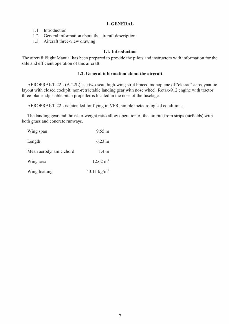
1.2. General information about the aircraft
AEROPRAKT-22L (A-22L) is a two-seat, high-wing strut braced monoplane of "classic" aerodynamic layout with closed cockpit, non-retractable landing gear with nose wheel. Rotax-912 engine with tractor three-blade adjustable pitch propeller is located in the nose of the fuselage.
AEROPRAKT-22L is intended for flying in VFR, simple meteorological conditions.
The landing gear and thrust-to-weight ratio allow operation of the aircraft from strips (airfields) with both grass and concrete runways.
Wing span 9.55 m
Length 6.23 m
Mean aerodynamic chord 1.4 m
Wing area 12.62 m2
Wing loading 43.11 kg/m2

8
1.3. AIRCRAFT THREE-VIEW DRAWING
9
2. LIMITATIO NS 2.1. Introductions 2.2. Airspeed 2.3. Airspeed indicator markings 2.4. Power plant 2.5. FLYdat – engine-monitoring instrument 2.6. Weight 2.7. Approved manoeuvres 2.8. Manoeuvring load factors 2.9. Flight crew 2.10. Kinds of operation 2.11. Instruments 2.12. Fuel 2.13. Other limitations 2.14. Limitation of engine operation at negative temperatures
2.1. Introduction Section 2 includes operating limitations, instrument markings, and basic tables necessary for safe opera-tion of the aircraft, its engine, systems and equipment.
2.2. Airspeed Airspeed limitations and their operational significance are shown in table 1.
Table 1
Symbol Speed IAS Remarks
VNE Never exceed speed 210 Do not exceed this speed in any operation
VA Max. manoeuvring speed 150 Do not make full or abrupt control movement above this speed, because under certain conditions the aircraft may be overstressed by full control movement
VF Max. flap extended speed 115 Do not exceed this speed with full flap deflection
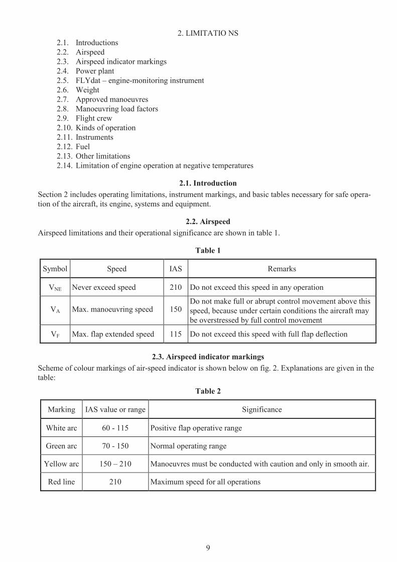
2.3. Airspeed indicator markings Scheme of colour markings of air-speed indicator is shown below on fig. 2. Explanations are given in the table:
Table 2
Marking IAS value or range Significance
White arc 60 - 115 Positive flap operative range
Green arc 70 - 150 Normal operating range
Yellow arc 150 – 210 Manoeuvres must be conducted with caution and only in smooth air.
Red line 210 Maximum speed for all operations
10
fig. 1 Airspeed indicator markings
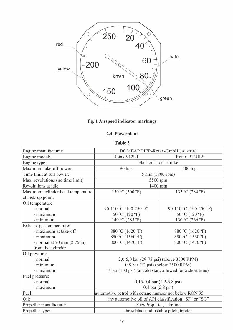
2.4. Powerplant
Table 3
Engine manufacturer: BOMBARDIER-Rotax-GmbH (Austria) Engine model: Rotax-912UL Rotax-912ULS Engine type: Flat-four, four-stroke Maximum take-off power: 80 h.p. 100 h.p. Time limit at full power: 5 min (5800 rpm) Max. revolutions (no time limit) 5500 rpm Revolutions at idle 1400 rpm Maximum cylinder head temperature at pick-up point:
150 ºC (300 ºF) 135 ºC (284 ºF)
Oil temperature: - normal - maximum - minimum
90-110 ºC (190-250 ºF)
50 ºC (120 ºF) 140 ºC (285 ºF)
90-110 ºC (190-250 ºF)
50 ºC (120 ºF) 130 ºC (266 ºF)
Exhaust gas temperature: - maximum at take-off - maximum - normal at 70 mm (2.75 in) from the cylinder
880 ºC (1620 ºF) 850 ºC (1560 ºF) 800 ºC (1470 ºF)
880 ºC (1620 ºF) 850 ºC (1560 ºF) 800 ºC (1470 ºF)
Oil pressure: - normal - minimum - maximum
2,0-5,0 bar (29-73 psi) (above 3500 RPM)
0,8 bar (12 psi) (below 3500 RPM) 7 bar (100 psi) (at cold start, allowed for a short time)
Fuel pressure: - normal - maximum
0,15-0,4 bar (2,2-5,8 psi)
0,4 bar (5,8 psi) Fuel: automotive petrol with octane number not below RON 95 Oil: any automotive oil of API classification “SF” or “SG” Propeller manufacturer: KievProp Ltd., Ukraine Propeller type: three-blade, adjustable pitch, tractor
200
250 2040
60
80100150
km/h
wite
green
yelow
red

11
2.5. FLYdat - engine-monitoring instrument A special combined instrument, FLYdat, is used for monitoring of engine operating parameters (fig. 3).
On FLYdat display, fig. 3, the following engine parameters data are indicated:
1 - RPM - engine speed, 1/min. revolutions per minute
2 - HOURS - hours of operation, ¥ 0.1 h 0.1 hour
3 - EGT/PTO - exhaust gas temperature, propeller side, "C degrees Celsius
4 - EGT/MAG - exhaust gas temperature, magneto side, "C degrees Celsius
5 - CHT - cylinder head temperature, "C degrees Celsius
6 - EGT display - indicates the line of cylinders from which the EGT is picked up, LEFT-RIGHT left or right
7 - OIL TEMP - oil temperature "C degrees Celsius
8 - OIL PRESS - oil pressure ¥ 0.1 bar
The FLYdat instrument is programmed for the following: - normal operation range, safe lower and upper limits; - take-off mode and warn limits; - each minimum and maximum value of alarm limit.
If the engine is running at speed less then 1,400 rpm then the red lamp “Battery discharge” is illuminated.
If all the engine parameters are within safe (normal range) limits then all their readings will be indicated by steady (non-blinking) figures.
If one or more parameters are out of safe limits then their readings will blink. At the same time alarm in-dicator will blink with period of 0.25 sec.
If one or more parameters are out of programmed alarm limits then their readings will be indicated by blinking figures and alarm indicator will give a steady light.
ROTAX
RPM1/min.
EGT/PTO°C
¥ 0.1hHOURS
°CEGT/MAG
EGT displayLEFT-RIGHT
¥ 0,1 barOIL PRESS
CHT°C
OIL TEMP°C
fig. 2. FLYdat display.
12
2.6. WeightMaximum take-off weight 472,5 kgMaximum landing weight 472,5 kgEmpty weight 280±10 kgMaximum luggage weight 20 kg
2.7. Approved manoeuvresAircraft "AEROPRAKT-22L" belongs to non-aerobatic category.
Manoeuvring should be within following limitations:- steep turns with bank angles not more than 60 degrees (flaps up or down);- sideslips with bank angles not more than 15 degrees at speed not exceeding 130 km/h.
2.8. Manoeuvring load factorsLimit load factors for the aircraft at gross weight of 472,5 kg are as follows:
Maximum positive limit load factor + 4Maximum negative limit load factor - 2
2.9. Flight crewThe flight crew may include 1 or 2 pilots.
Flying the aircraft with a load in the luggage container heavier 20 kg is strictly FORBIDDEN.
2.10. Kinds of operationThe aircraft may be operated only in daytime, under VFR conditions and when there is no danger of icing.
It can be used for following missions:- primary training;- sport competition;
after installation of appropriate equipment it also can be used for:- air surveillance and photography;- any other application within the aircraft performance.
13
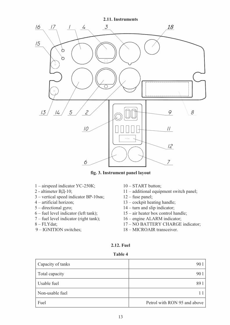
2.11. Instruments
fig. 3. Instrument panel layout
1 – airspeed indicator УС-250К; 2 - altimeter ВД-10; 3 – vertical speed indicator ВР-10мк; 4 – artificial horizon; 5 – directional gyro; 6 – fuel level indicator (left tank); 7 – fuel level indicator (right tank); 8 – FLYdat; 9 – IGNITION switches;
10 – START button; 11 – additional equipment switch panel; 12 – fuse panel; 13 – cockpit heating handle; 14 – turn and slip indicator; 15 – air heater box control handle; 16 – engine ALARM indicator; 17 – NO BATTERY CHARGE indicator; 18 – MICROAIR transceiver.
2.12. Fuel
Table 4
Capacity of tanks 90 l
Total capacity 90 l
Usable fuel 89 l
Non-usable fuel 1 l
Fuel Petrol with RON 95 and above

14
2.13. Other limitations This aircraft is approved as one of ultralight category and can be operated only in the day-time, under VFR and when no icing is possible.
Wind limitation for "AEROPRAKT-22L" are as follows: - head wind up to 10 meters per second; - cross wind up to 4 meters per second;
WARNING!
# It is highly recommended to choose upwind direction for take-off and landing with the least cross wind. It will significantly shorten take-off and landing distances and increase degree of safety.
# All aerobatic manoeuvres including intentional spins are PROHIBITED.
2.14. Limitation of engine operation at negative temperatures Engine Operator’s Manual prescribes some limitation of engine operation at negative temperatures.
At negative temperatures of ambient air icing of the carburettor, change in fuel-air mixture, loss of power and freezing of fuel lines are possible. Negative temperature can affect the carburettor adjustment.
Operating temperature range for Rotax-912 engine is from -25 ºC to +50 ºC.
15
3. EMERGENCY PROCEDURES 3.1. Introduction 3.2. Engine failure 3.3. Restarting the engine in flight 3.4. Fire 3.5. Landing with engine stopped 3.6. Spin recovery 3.7. Pitot/static system failure 3.8. Radio failure 3.9. Flying in dangerous meteorological conditions 3.10. Landing out of airfield
3.1. Introduction Section 3 contains recommendations to the pilots in case of emergency in flight. However such situations, caused by airframe or engine malfunction are extremely rare provided that pre-flight inspections and checks are made regularly.
3.2. Engine failure 1. In case of engine failure during take-off roll switch OFF the engine ignition system and discontinue the
take-off.
2. If the aircraft is at altitude up to 50 meters switch the engine OFF and land right ahead avoiding head-on collision with any obstacles.
3. If the engine failed during climb, set the aircraft into a steady descent at a speed of 90 km/h and if the altitude is sufficient turn the airplane toward the airfield, switch the ignition off, and make landing.
4. In case of engine failure during level flight set the aircraft into steady descent at a speed of 90 km/h, switch the ignition off, estimate wind direction and strength, choose a place for landing and land (pref-erably into the wind). Under favourable flight conditions try to restart the engine in flight (see para-graph 3.3). If the altitude is not sufficient, land.
5. If there is no place for landing and conditions do not allow restarting the engine in flight, use the re-covery system (installed as an option).
Recommendations to the crew. While descending on the parachute of recovery system the aircraft may rotate. In connection with this the crew is recommended to do the following:
- using ailerons and rudder try to stop the rotation. - the pilots should adopt a safe position to avoid possible injuries from impact in case of rough landing.
3.3. Restarting the engine in flight To restart the engine in flight:
- set the throttle lever at idle; - set the ignition switches into ON position; - turn the key to start the engine.
3.4. Fire In case of fire on board crew should act as follows:
- shut off the fuel taps; - switch the ignition OFF; - set the aircraft into a steady descent; - make emergency landing or deploy the recovery system.

16
3.5. Landing with engine stopped This aircraft has no peculiar handling features during the landing with stopped engine and flaps up or down. Recommended speed at descent - 90 km/h, entry into the flare at 5 meters, flare out at 0.5 m, land-ing speed 60 km/h. Maximum gliding ratio for the aircraft is approximately 10.
3.6. Spin recovery WARNING: Intentional spins on the aircraft are prohibited.
NOTE: In level flight and during turn stall approach warning is provided by the aerodynamic characteris-tics of the aircraft - shaking of aircraft structure and control yoke.
To recover the aircraft from the spin (unintentional stall) push forward the rudder pedal opposite to the di-rection of spin and then push the yoke fully forward. When the rotation ceases put the rudder in neutral position and after reaching speed of 80 km/h smoothly level off the aircraft without exceeding the load factor of +4 and maximum allowed speed of 200 km/h.
3.7. Pitot/static system failure 1. Pitot tube blockage
Signs of the malfunction: - in level flight readings of airspeed indicator do not change with speed changing; - during descent airspeed readings decrease and during climb increase.
Crew actions: - Do not use airspeed indicator readings. In level flight set the engine speed to 4100-4300 rpm, the
airspeed at that will be 100-110 km/h. While descending reduce the engine speed to idle set the sink rate of 4 m/s in this case the airspeed will be approximately 110 km/h.
2. Static tube blockage Signs of the malfunction:
- readings of vertical speed indicator and altimeter do not change with altitude changing; - during descent airspeed readings increase and during climb decrease.
Crew actions: - Do not use readings of airspeed indicator. - Check the airspeed by FLYdat (tachometer) readings only.
3.8. Radio failure NOTE: Radio transceiver is installed as an option.
If there is no radio transmission/reception make sure that: - the radio is switched on; - the frequency is set correctly; - headset cable is plugged into the radio set.
Crew actions: - Set VOLUME to maximum, SQUELCH to OFF. - Check the radio connection at other frequencies.
3.9. Flying in dangerous meteorological conditions Flying in dangerous meteorological conditions means flying in conditions when icing is possible, during thunderstorm, dust storm and strong turbulence.
Pay attention continuously to flight condition changes. If flight conditions begin to deteriorate take deci-sion in time to change the route or discontinue the flight.
WARNING: Flying in conditions when icing is possible is FORBIDDEN! In case of getting into such conditions the crew must leave the hazardous area immediately, and land at the nearest airfield or suitable place.
17
WARNING: Flying in the vicinity of thunderstorm is FORBIDDEN!
Having noticed the thunderstorm area estimate the available time, the direction of thunderstorm approach-ing and land at the nearest airfield or a suitable place. Tie down and cover the aircraft. The control surfac-es must be secured with clamps or stops, the canopy must be locked reliably.
Strong turbulence may be very dangerous. Avoid it in flight taking in time the decision to change the route or discontinue the flight.
In case of getting in strong turbulence at low altitude climb immediately to higher altitude flying away from the source of turbulence.
During strong turbulence the airspeed must be not less then 100 km/h but not more then 140 km/h, alti-tude at least 100 m. Turns must be performed with bank angle up to 30".
In case when flying into turbulence can not be avoided choose an open field and land trying not to exceed the limit values of speed and bank angle.
WARNING: DO NOT FLY INTO A CLOUD!
In case of getting into a cloud fly out of it descending and checking the airspeed and bank angle. When hori-zon line is obscured by the cloud the bank angle may be checked by vertical orientation of compass reel.
Wind shear effect on the aircraft Wind shear - difference in wind direction and velocity at low altitudes getting into which the aircraft may be suddenly shifted from the desired flight path. The wind shear is most dangerous when the aircraft is at final stage of flight, i.e. during final approach. Due to increase of tailwind component or decrease of headwind component near the ground the airspeed decreases, the lift drops, the sinking rate increases. Such situation may occur suddenly and the crew should know when and where this phenomenon may be expected and should be ready to act accordingly to ensure safe flight and landing.
Most often the wind shear is connected with: - passing fronts; - forming of thunderstorm clouds; - significant inversion at altitude 50-200 m.
When expecting wind shear the approach must be performed at speed 100 km/h minimum. The crew must be ready to increase engine speed to full power and go-around.
Getting into wake turbulence Getting into wake turbulence of another (especially large) aircraft may be very dangerous. The wake tur-bulence is created by propeller slipstream, wing and fuselage generated vortices. Getting into wake turbu-lence may cause complete loss of aircraft control. Most dangerous the wake turbulence is during the take-off, initial climb, final approach and landing.
WARNING: Avoid getting into wake turbulence!
3.10. Landing out of airfield In case when outlanding is imminent the pilot should do the following:
- select a suitable place for landing; - determine the wind direction looking at land features (smoke, trees, etc.); - make landing.
When landing on a place with dense and high vegetation (crops, bushes, etc.), select the top of it as ground level for leveling off.
Emergency landing on water (ditching) or forest must be done by flaring with fully extended flaps.
When landing on forest select the densest part of it selecting tree tops as ground level for flaring.
When ditching, unfasten the seat belts in advance in order to leave the aircraft promptly. For selecting the flare altitude use water surface as ground level.

18
4. NORMAL OPERATION 4.1. Aircraft assembly and disassembly 4.2. Pre-flight checks 4.3. Flight
4.1. Aircraft assembly and disassembly Procedures of the aircraft assembly and disassembly are described in Chapter 2, paragraph 2.4, AEROPRAKT-22L Aircraft Maintenance Manual.
4.2. Pre-flight checks Pre-flight inspection of the aircraft: Before the flight pilot must inspect the aircraft. It is recommended to inspect the aircraft in the following order:
- power plant; - landing gear; - right-hand wing; - right-hand side of the fuselage; - tail unit; - left-hand side of the fuselage; - left-hand wing; - cockpit.
Power plant Inspect the propeller and its spinner: make sure that there are no nicks and other damage. Inspect engine cowling: make sure that all locks are locked properly. Make sure that there are no leaks of fuel, oil or coolant from the engine.
Landing gear Make sure that landing gear is not damaged. Inspect the wheel tires and discs. Check the tire inflation (de-flection 20 - 30 mm) and secure attachment of the wheel spats.
Right-hand wing, fuselage side and tail unit
- Make sure that the wing covering is not damaged, flaperon attachment is intact, and there is no leak of fuel from the wing tank.
- Make sure that the fuel filler cap is closed tight.
- Check the fuselage skin for damage.
- Inspect the battery, control rod and cables through the transparent covering of fuselage.
- Make sure that the empennage skin has no damage and that attachment fittings of elevator, rudder and elevator trim tab are intact.
- Make sure that Pitot tube cover is removed. Check condition and attachment of the Pitot tube.
- Make sure that the amount of fuel, oil and coolant is adequate for the planned flight.
- The aircraft must be cleaned from snow and dirt.
It is strictly FORBIDDEN to fly the aircraft which is even partly covered with hoar, snow or ice.
Pre-flight inspection of the cockpit by pilot
- Inspect the interior of the cockpit and make sure that its equipment is intact and there are no foreign objects.
- Fit the harness belts to your size.
19
- Make sure that the cockpit glazing is clean and has no damage.
- Make sure that the recovery system is ready for deployment (safety pin is removed from the firing device).
- Make sure that the controls are not secured with stops.
- Make sure that the full and static pressure lines are free of water.
Sitting in the pilot seat check the following: - all control levers are in initial position; - controls move freely and correctly; - the trim tab lever is in its neutral position; - inspect the instrument readings and judging by their readings make sure that they are intact - altimeter is intact (by setting its altitude reading to 0 and comparing its pressure reading to actual at-
mospheric pressure at the airfield); - condition of the engine control system; - readings of the magnetic compass, which should give the magnetic course; - amount of fuel in the tank; - starter key is out of starter lock and ignition switches are set to OFF position.
Before starting the engine: Just before the engine start do the following:
- set the throttle lever to idle; - put the choke handle fully forward.
Before starting cold engine it is recommended to turn the engine with starter for 5 seconds without switching on the ignition, for that the pilot gives the “Clear prop!” command and hearing “Prop clear!” or making sure that the command is obeyed, turns the key to start the engine (DO NOT switch on the ig-nition).
Engine start Warn those who are standing close to the aircraft by command “Clear prop!” that you are going to start the engine. Having obtained “Cleared!” reply or seeing that your command has been obeyed insert the key into the ignition lock, set it to 1st position and make sure that FLYdat is working properly, switch the igni-tion ON and only after that press the wheel brake handle and turning the key to 2nd position start the en-gine. Engine will start running at idle. Warm the engine up to the normal oil temperature of 50 "C.
Emergency engine stop To stop the engine immediately switch OFF ignition switches.
4.3. Flight Preparation to taxiing and taxiing
Before taxiing make sure that the oil temperature is at least 50ºC and that the taxi way is clear.
The required speed of taxiing is chosen depending on the taxiway condition, visibility and presence of ob-stacles. Keep direction of taxiing and make turns using steerable nose wheel.
To check the brakes set the engine speed to idle, pedals in neutral position and pull the brake lever gently.
WARNING! - Abrupt braking at a high speed may cause the aircraft going nose over.
- During the taxiing with the cross wind the aircraft tends to turn into the wind.
- If the wind is stronger than 10 m/s during taxiing the aircraft should be followed by someone from the windward side near the wing tip.

20
Prior to take-off - Taxi onto the runway orienting the aircraft into the wind if possible; - move straight 2 or 3 m forward to set the nose wheel into neutral position and stop; - check the primary controls by moving them from stop to stop; - check the engine parameters; - check position of the flaps and elevator trim tab lever.
Take-off If the runway is clear, release the brakes, increase the engine speed gradually until the aircraft starts mov-ing then increase the engine RPM to take-off.
In the beginning of the take-off roll hold the yoke in neutral position, after reaching speed of 40 km/h raise the aircraft nose to take-off attitude by pulling the yoke gently backward. Maintain the direction of take-off using rudder.
Lift-off occurs at speed of 65 km/h. After lift-off accelerate the aircraft at 1-2 m altitude up to a speed of 90-100 km/h and then start the climb. Take-off without using the wing high-lift devices is the simplest and has no peculiar features. The aircraft easily maintains the direction during take-off roll.
If it is necessary to achieve the shortest take-off run and distance pilot should extend the flaps to the take-off (first) position. When choosing the flaperon setting it is necessary to take into account the strength of the headwind. With a headwind of 8 m/s and more extending of flaperon is NOT RECOMMENDED.
There are no peculiar features in aircraft handling with flaps extended.
At an altitude of about 50 m, maintaining the take-off power of the engine, retract the flaps slowly by set-ting them from first position to “zero” within 3 seconds.
Take-off with cross wind component Take-offs are allowed with a cross wind component not stronger than 4 m/s.
Take-off with the cross-wind must be done without extending the flaps. The aircraft tends to turn into the wind during take-off, so the yoke should be moved to the wind side from the very beginning of the take-off run. This is necessary for maintaining equal loads on main landing gear wheels, preventing the bank-ing and turning of the aircraft into the wind.
As the speed of aircraft and ailerons efficiency increase gradually return the yoke to the neutral position to prevent the aircraft from leaving the ground from one wheel.
If aircraft is starting to turn during take-off it is necessary to stop this tendency deflecting the rudder (pressing the pedal) to the side opposite to the turn.
After lift-off in order to prevent the drifting it is necessary to turn the aircraft slightly into the wind.
When taking-off with a cross-wind the lift-off speed should be by 5-10 km/h higher than normal.
Climb Recommended speed at climb is 90-100 km/h. At an altitude of 50 m use the trim tab to decrease control yoke force. During the climb it is necessary to check constantly the engine temperature and speed.
Level flight During the level flight the aircraft is stable, easily controllable within the entire speed range and any oper-ational centre of gravity position. The control yoke force in pitch may be removed with elevator trim tab deflection.
Steep turns are allowed at the height not less than 50 m with the bank angle not more than 60 degrees. Pe-riodically check the amount of fuel in the fuel tank. To ensure equal fuel level in left and right tanks use their shut-off valves in turn.

21
In turbulent air the speed should be not less than 100 km/h, altitude height not less than 100 m. Turns should be made with bank angle not more than 30 degrees.
Approach and landing Having obtained the clearance to proceed to final and information on weather condition adjust the altime-ter according to airfield pressure.
Make final turn at an altitude at least 100 m at 1000 m distance from the airfield.
At the altitude of not less than 50 meters set the flaps in landing position taking into account the strength of the wind.
It is NOT RECOMMENDED to extend the flaps with headwind more than 8 m/s.
After entering into final set the throttle to idle and descent at a speed of 90-100 km/h. Pay attention to changing of altitude, maintain zero bank and drift.
When you are too low DO NOT RETRACT the flaps, as this will cause some loss of altitude. This error should be corrected by increasing the engine RPM.
When you are too high correct the error by side-slipping.
Entry into the flare at 4-5 meters, flare out at approximately 0.2-0.3 m. Yoke motion should be energetic but smooth and continuous until the touch-down. Land softly on the main wheels. When landing look to the left side at an angle of 10 to 15 degrees to the aircraft axis and 15 to 20 m forward of it slipping with your glance over the airfield surface.
During the flare attention should be also shared between the following: - determining the altitude and vertical speed; - controlling the drift and bank angles; - controlling the direction of flight.
After touch-down retract the flaps at a speed of 40 km/h. Maintain the direction during the landing run with rudder.
Use of brakes for shortening the landing run is recommended only after the nose wheel touches the ground.
In case of landing with flaps retracted the glide path is shallower, landing speed and landing distance slightly increase.
Cross-wind landing The landing may be allowed if the cross-wind component is not higher than 4 m/s. Do not use flaps during cross-wind landing.
As the cross-wind landing is more complicated and in order to reduce the cross-wind component it is RECOMMENDED to choose in-wind direction of landing.
The lateral wind component: - causes drift of the aircraft in the air or; - turns the aircraft into the wind on the ground.
On approach apply a little bank opposite to the wind direction to counter the drift and use the rudder to maintain the direction. When entering into the flare start to decrease the bank slowly so that the aircraft touches down with the wing parallel to the ground.
If just before the touch-down there is a drift turn the aircraft with the rudder pedals towards the drift to lessen the side impact on the landing gear.
Go-around Go-around is possible from any altitude with flaps both up and down. When going around push the throt-tle fully forward. Climb at a speed of 90-100 km/h. Retract the flaps at an altitude at least 50 meters over the obstacles leaving the engine at a full throttle, repeat the circuit and approach patterns.

22
After landing After landing clear the runway and taxi to the parking.
Stop the engine by doing the following: - set the minimum engine speed using throttle lever; - set ignition switches to OFF.
Post-flight inspection If everything was OK with the aircraft during the flight then after the lading check visually:
- for leaks of fuel or oil; - condition of the propeller blades; - condition and inflation of tires; - landing gear legs for deformation, cracks and other damage.
Check the condition of the fabric covering of the wing, flaperons, elevator and rudder.
When flying at low temperatures pay a special attention to elimination of blockage and freezing of the pressure lines and static ports.
Refuel if necessary.
23
5. PERFORMANCE 5.1. Introduction 5.2. Stall speed 5.3. Take-off distance 5.4. Landing distance 5.5. Climb performance 5.6. Level flight at cruising speed 5.7. Flight endurance 5.8. Climb performance at go-around 5.9. "Bug" effect
5.1. Introduction Section 5 describes the flight performance of AEROPRAKT-22L aircraft as well as limitations of the per-formance.
5.2. Stall speed The stall speed with flaps set to second position at maximum take-off weight and engine at idle is equal to 60 km/h, with flaps in 1st position - 65 km/h, with retracted flaps - 70 km/h.
The stall speed with flaps retracted during the turn with bank angle 60 degrees is equal to 95 km/h, with bank angle 30 degrees - 75 km/h.
5.3. Take-off distance Take-off distance is a sum of take-off run and distance flown from lift-off to reaching of 15 m altitude.
The take-off distance at any conditions of take-off and maximum take-off weigh does not exceed 250 m.
5.4. Landing distance Landing distance is a sum of distance flown from 15 m altitude to touch-down and landing run. In any conditions of landing and at maximum take-off weight it does not exceed 350 m.
5.5. Climb performance The aircraft rate of climb depends on ambient air temperature and take-off weight. Climb shall be per-formed at the speed of the highest climb rate which is 90-100 km/h. The climb rate at maximum take-off weight near the ground level is at least 3 m/sec.
5.6. Level flight at cruising speed The cruising speed of level flight is 130 km/h, engine revolutions – 4400 RPM.
5.7. Endurance Maximum flight endurance of the aircraft at a low altitude and full fuel tanks (90 l) is equal to 10 hours.
5.8. Climb performance at go-around Go-around procedure shall be done at the speed of maximum rate of climb (90-100 km/h) with engine at maximum power.
5.9. "Bug" effect Bugs and raindrops affect the aircraft performance insignificantly, and as there is no wiper on the wind-screen they worsen the visibility in flight.
24
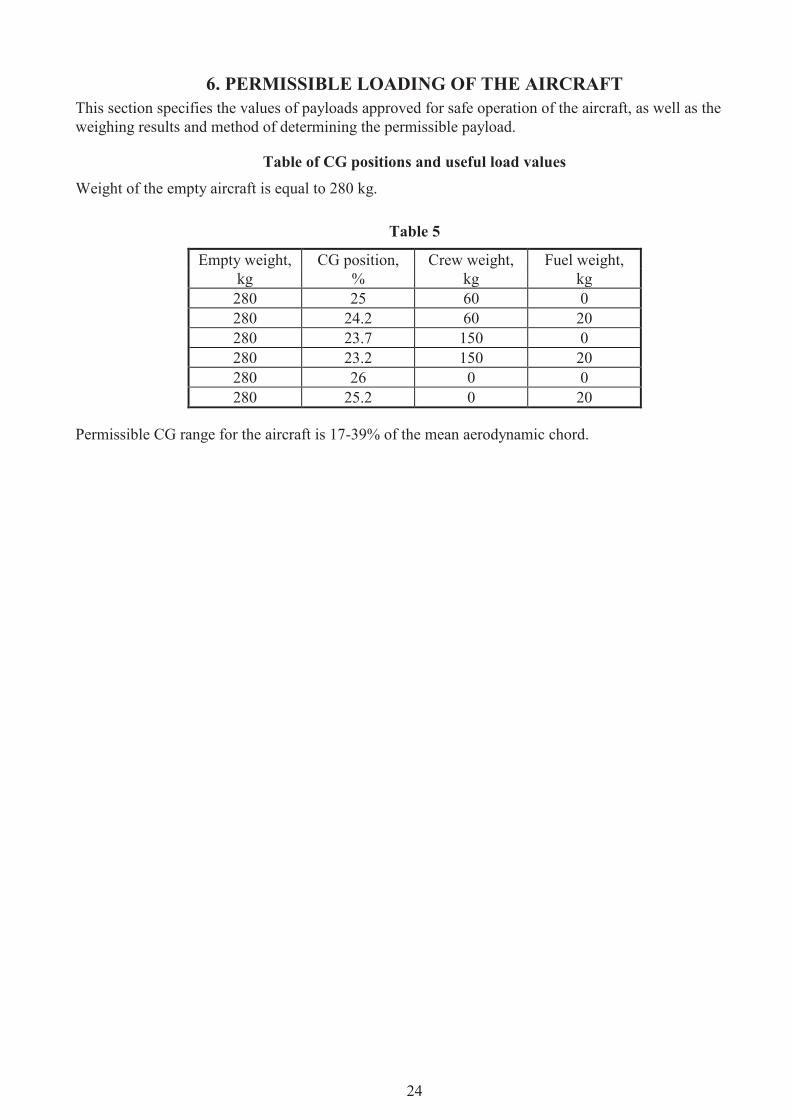
6. PERMISSIBLE LOADING OF THE AIRCRAFT This section specifies the values of payloads approved for safe operation of the aircraft, as well as the weighing results and method of determining the permissible payload.
Table of CG positions and useful load values Weight of the empty aircraft is equal to 280 kg.
Table 5
Empty weight, CG position, Crew weight, Fuel weight, kg % kg kg 280 25 60 0 280 24.2 60 20 280 23.7 150 0 280 23.2 150 20 280 26 0 0 280 25.2 0 20
Permissible CG range for the aircraft is 17-39% of the mean aerodynamic chord.