Embed Size (px)
Citation preview

University of Plymouth
PEARL https://pearl.plymouth.ac.uk
The Plymouth Student Scientist - Volume 10 - 2017 The Plymouth Student Scientist - Volume 10, No. 2 - 2017
2017
Flexural behaviour of BFRP rebar
reinforced concrete beams
Rudzinskis, E.
Rudzinskis, E. (2017) '
http://hdl.handle.net/10026.1/14163
The Plymouth Student Scientist
University of Plymouth
All content in PEARL is protected by copyright law. Author manuscripts are made available in accordance with
publisher policies. Please cite only the published version using the details provided on the item record or
document. In the absence of an open licence (e.g. Creative Commons), permissions for further reuse of content
should be sought from the publisher or author.

The Plymouth Student Scientist, 2017, 10 (2), 134-170
134
Flexural behaviour of BFRP rebar reinforced
concrete beams
Edgaras Rudžinskis
Project Advisor: Dave Easterbrook, Plymouth University, Drake Circus, Plymouth,
PL4 8AA
Abstract
Deterioration of concrete structures caused by corrosion of the steel reinforced bar (rebar) inside the structures has led to a significant focus on developing more efficient and sustainable alternatives. Several studies have investigated the ability of Basalt Fibre Reinforced Polymer (BFRP) to be used for structural application in concrete beams. However, the findings have been variable suggesting a more refined experimental model to produce more robust results is needed. Therefore, the overall aim of this study was to improve the current understanding of BFRP rebar reinforced concrete beams’ flexural behaviour. Four class C28/35 concrete beams, reinforced with 8 mm diameter reinforcement elements, made of BFRP and traditional steel, were tested under flexure. The main actions carried out in the experiment were firstly, the recording of failure load and mid-span vertical displacements of the beams. Secondly, observation and investigation of failure modes by removing the concrete from the reinforcement of the tested beams. Thirdly, the investigation of how different reinforcement setups affected BFRP reinforced concrete beam flexural behaviour. Fourthly, the comparison of cracked and un-cracked section behaviour of BFRP and traditional steel rebar reinforced concrete beams. The fifth action was an assessment of whether traditional steel reinforcement principles are suitable for designing BFRP reinforcement for concrete beams. Lastly, crack propagation between BFRP and traditional steel reinforced concrete beams was compared. The results showed a very good correlation between experimental results and predicted ultimate load and deflection values obtained using traditional steel reinforcement design principles. It was found that the un-cracked sections of the BFRP reinforced concrete beam behaviour is virtually identical to steel reinforced beams, but the cracked section behaved completely differently. Also, beams reinforced with BFRP tension bars that were anchored displayed less deflection. Detailing issues using BFRP and steel hybrid reinforcement system were discovered, therefore further investigation including the proposed setup solutions from this study, needs to be carried out to determine whether they strengthen the evidence for hybrid reinforcement systems using BFRP reinforced concrete beams.

The Plymouth Student Scientist, 2017, 10 (2), 134-170
135
Contents 1. Introduction ........................................................................................................ 137
2. Literature review ................................................................................................. 137
3. Experimental beam setup (Method) ................................................................... 142
3.1 Tensile strength tests ................................................................................ 143
3.2 Concrete design of the beams .................................................................. 145
3.3 Reinforcing cage ....................................................................................... 146
3.4 External load setup ................................................................................... 147
Results ................................................................................................................... 149
4.1 Failure modes ........................................................................................... 149
4.2 Beam B1 - control beam ........................................................................... 150
4.3 Beam B2 – bottom basalt bars lapped with steel L bars ........................... 150
4.4 Beam B3 – bottom basalt bars (not anchored ends) ................................. 151
4.5 Beam B4 – bottom basalt bars lapped with steel L bars ........................... 152
4.6 Comparison of all four beams’ behaviour .................................................. 153
4.7 Un-cracked section deflection ................................................................... 154
4.8 Cracked section deflection ........................................................................ 155
5. Visual inspection ................................................................................................ 156
5.1 Beam B1 (control beam) ........................................................................... 156
5.2 BFRP rebar reinforced concrete beam B2 ................................................ 157
5.3 BFRP rebar reinforced concrete beam B3 ................................................ 158
5.4 BFRP rebar reinforced concrete beam B4 ................................................ 159
6. Discussion .......................................................................................................... 159
6.1 Tensile test ................................................................................................ 159
6.2 Constructability .......................................................................................... 160
6.3 Results ...................................................................................................... 161
6.3.1 Control beam (B1) .............................................................................. 161
6.3.2 Un-cracked section ............................................................................. 161
6.3.3 Cracked section .................................................................................. 162
6.4 Visual inspection ....................................................................................... 163
6.4.1 Beam B1 ............................................................................................. 163
6.4.2 Beam B2 ............................................................................................. 164
6.4.3 Beam B3 ............................................................................................. 164
6.4.4 Beam B4 ............................................................................................. 164
6.4.5 Summary of visual inspection ............................................................. 165
6.5 Real-life situation representation ............................................................... 166
7. Conclusions ........................................................................................................ 166

The Plymouth Student Scientist, 2017, 10 (2), 134-170
136
8. Future work improvements ................................................................................. 167
9. Reference List .................................................................................................... 169

The Plymouth Student Scientist, 2017, 10 (2), 134-170
137
1. Introduction In recent years, there has been a significant focus on developing and inventing new sustainable more efficient materials to replace traditional steel reinforced bars (rebar) that are used in concrete structural elements. This is predominately due to deterioration of concrete structures being caused by the corrosion of the steel rebar inside the structure (American Concrete Institute Committee 440, 2006). The ability of Basalt Fibre Reinforced Polymer (BFRP) to be used for structural application in concrete beams has been investigated in several studies. The variable findings in these studies implicated that a further refined experimental model needed to be developed to produce results that are more robust (Fan & Zhang, 2016; Gohnert, Gool & Benjamin, 2014; Lapko & Urbanski, 2014). Therefore, the overall aim of this study was to improve the current understanding of BFRP rebar reinforced concrete beams’ flexural behaviour
The following objectives were outlined in this study to meet the overall aim: firstly, to determine the mechanical properties of BFRP rebar and compare them with the mechanical properties of steel rebar. Secondly, to investigate how different BRFP rebar reinforcement setups affect the flexural performance of the concrete beam. Thirdly, to determine whether and how the slippage phenomenon affects flexural behaviour and load taking capacity of BFRP rebar reinforced concrete beams. Lastly, to test the level of accuracy of traditional steel reinforcement design principles used to design the BFRP rebar reinforced concrete beams.
2. Literature review
BFRP rebar concrete beams subjected to flexure Research into alternatives to steel rebar to replace traditional rebar used in concrete structural elements have included basalt, glass, carbon and aramid rebar (Dhand et al., 2015; Fiore et al., 2015; Gohnert, Gool & Benjamin, 2014; Lapko & Urbanski, 2014; Urbanski, Lapko & Garbacz., 2013). It has been found that the performance of glass, carbon and aramid as rebar are affected by the alkaline environment within the concrete causing them to breakdown, whereas basalt as an alternative does not break down in the alkaline environment (Fan & Zhang, 2016).
Basalt is a naturally occurring volcanic rock that originates from frozen lava that can be found in abundance in the Earth's crust. Basalt Fibre Reinforced Polymer (BFRP) rebar is formed by crushing basalt rock into a powder which is then heated to melting point (approximately 1450 degrees Celsius). A fine nozzle is then used to extrude the molten material to form a thin continuous strand. These strands are bundled and bound together by using a polymeric compound, to produce long straight rebars. Often supplementary BFRP strands are used to form spiral ribbing, by winding them transversely around the rebar, to provide containment and rigidity to the rebar and increase the strength of the mechanical anchorage between the concrete and rebar (Gohnert, Gool & Benjamin, 2014). Figure 1 demonstrates the finished product of BFRP rebar.

The Plymouth Student Scientist, 2017, 10 (2), 134-170
138
Figure 1: Basalt Fibre Reinforced Polymer rebar.
Aside from its ability not to corrode in an alkaline environment, BFRP rebar has a wide range of beneficial properties including resistance to heat and a weight that is much lighter compared to steel, making the rebar easier to handle during installation (Fiore et a., 2015). BFRP rebar possesses a high tensile strength. Several studies have shown that when carrying out rebar maximum tensile capacity tests, the tensile stress of BFRP rebar is almost twice that of steel rebar (Gohnert, Gool & Benjamin, 2014). BFRP rebar is significantly cheaper to produce than other rebar including glass and carbon rebar. Overall cost of structures using BFRP rebar could further be reduced by decreasing the nominal covers of concrete reinforcement due to BFRP rebar not being susceptible to corrosion. The reduction of the cover would reduce the self-weight of the structure and eliminate the need for building maintenance due to corrosion (Dhand et al., 2015; Fiore et a., 2015; Gohnert, Gool & Benjamin, 2014). Other benefits of BFRP rebar include the natural resistance of BFRP rebar to ultraviolet (UV) and the resistance of BFRP rebar to fire, as unlike steel rebar, when subjected to heat, BFRP rebar does not lose its strength and result in structural failure (Zhu et al, 2014; Ross, 2006).
Nevertheless, there are several weaknesses associated with BFRP rebar including low elastic modulus which causes high deflections in concrete elements (Gohnert, Gool & Benjamin, 2014; Urbanski, Lapko & Garbacz., 2013). Furthermore, rebar slippage in concrete beams is a significant drawback which is caused by anchorage problems (Gohnert, Gool & Benjamin, 2014). BFRP rebar also has some constructability limitations as it cannot physically be bent and therefore only straight reinforcing bars can be used in construction which can complicate contractors work (Gohnert, Gool & Benjamin, 2014; Sim, Park & Moon, 2005).
Several studies have investigated the ability of BFRP fibre sheets and BFRP rebar for structural application in concrete beams, subjected to flexure (Fan & Zhang, 2014; Shafiq, Ayub & Khan, 2016; Ge et al., 2015; Gohnert, Gool & Benjamin, 2014; Lapko & Urbanski, 2014; Urbanski, Lapko & Garbacz., 2013). However, it appears that only three of these studies have successfully compared the mechanical properties of BFRP rebar used in concrete beams with a reference beam made with steel rebar (Fan & Zhang, 2016; Gohnert, Gool & Benjamin, 2014; Lapko & Urbanski, 2014).
Gohnert, Gool & Benjamin, (2014) undertook a study on the behaviour of BFRP rebar concrete beams that had been subjected to flexure. Six samples of BFRP rebar, with

The Plymouth Student Scientist, 2017, 10 (2), 134-170
139
a diameter of8mm, located at the bottom of the concrete beam where the tension zone is, were tested alongside six samples of steel equivalent diameter rebar reinforced concrete beams. In all twelve of the samples, steel shear links, steel U-rebars and steel rebar at the top of concrete beam cross-section were used. See Gohnert, Gool & Benjamin, (2014) for the experimental setup used.
Lapko & Urbanski (2014) conducted a similar experiment to Gohnert, Gool & Benjamin (2014) to study the behaviour of BFRP rebar concrete beams that had been subjected to flexure. However, Lapko & Urbanski (2014) used a different setup as only six concrete beams were used (three steel rebar beams and three BFRP rebar beams) compared with Gohnert, Gool & Benjamin (2014) where there was a total of twelve beams (six steel rebar and six BFRP rebar). See Lakpo & Urbanski (2014) for the experimental setup.
Compared to Gohnert, Gool & Benjamin (2014), the BFRP rebar concrete beams used in Lakpo & Urbanski (2014) did not have shear links or top steel reinforcement in the middle region of the beam. Also, similar to Gohnert, Gool & Benjamin (2014), in the tension zone at the bottom of the concrete beam, BFRP 8mm diameter rebars were used, although three rebars were used in Lapko & Urbanski (2014), unlike Gohnert, Gool & Benjamin (2014) where only two were used on each beam. In Lapko & Urbanski (2014), the middle BFRP rebar was placed protruding through the ends of the concrete beam on each side. This is different to Gohnert, Gool & Benjamin (2014) as they did not have the middle rebar protruding. Furthermore, the concrete beams used in Lapko & Urbanski (2014) did not have U-rebars at each end of the beams anchoring the BFRP rebar at each end of the beam.
Fan & Zhang (2016) conducted a study that was very similar to Lapko & Urbanski (2014); however, the main difference was the type of concrete used. Fan & Zhang (2016) used an inorganic polymer (geopolymer) concrete instead of an ordinary Portland concrete. This was due to the need for a more environmentally sustainable type of concrete to dominate the construction and building products industry to decrease the percentage of global CO2 emissions that are currently produced from man-made concrete infrastructure (Juenger & Siddique, 2015). The setup of the concrete beams in Fan & Zhang (2016) differed from Gohnert, Gool & Benjamin (2014) and Lapko & Urbanski (2014) as two BFRP rebars were located at the bottom of the beam with a diameter of 12mm and two steel rebars with a diameter of 14mm at the bottom of the beam. See Fan & Zhang (2016) for the experimental setup.
There were further ways that the experimental setups differed between the three studies. Firstly, the load distribution across the beam was very wide in Gohnert, Gool & Benjamin (2014) compared to Lapko & Urbanski (2014) and Fan & Zhang (2016). In fact, the load setup in Gohnert, Gool & Benjamin (2014) was so widely distributed it resulted in the shear span ratio being only 0.75 which was very low compared to Lapko & Urbanski (2014) and Fan & Zhang (2016) which were 2.4 and 3.3 respectively. Moreover, Lapko & Urbanski (2014) and Fan & Zhang (2016) omitted shear links in the middle span region in order to subject the mid-span of the beams to pure bending whereas Gohnert, Gool & Benjamin (2014) placed shear links across a whole span of beams. Finally, it is important to note that Fan & Zhang (2016) and Lapko & Urbanski (2014) omitted not only shear links but longitudinal top steel reinforcement in the middle region of the beam, whereas Gohnert, Gool & Benjamin (2014) left longitudinal top reinforcement rebars spanning the full length of the beam.
The Plymouth Student Scientist, 2017, 10 (2), 134-170
140
There were similarities and differences between the results in Fan & Zhang (2016), Gohnert, Gool & Benjamin (2014) and Lapko & Urbanski (2014). Beam failure was reported in all three of the studies; Gohnert, Gool & Benjamin (2014) reported that beam failure was caused by BFRP rebar slippage. Fan & Zhang (2016) reported that both steel rebar and BFRP rebar reinforced beams failed in compression i.e. tensile capacity of the BFRP rebar was not reached. Failure in Lapko & Urbanski (2014) occurred by the crushing of concrete in the compression zone due to section being over-reinforced. Lapko & Urbanski (2014) argued that beam failure did not occur in bending, instead shear failure occurred. Fan & Zhang (2016), Gohnert, Gool & Benjamin (2014) and Lapko & Urbanski (2014) failed to test BFRP rebar in the reinforced beams, as failure occurred by either concrete crushing in the compression zone, or BFRP rebar slippage but not failure of the bottom rebar.
It is important to design tension (bottom) reinforcement so that it is not greater than then concrete crushing capacity in order to avoid beam failure in compression, which is sudden failure. This failure occurred in the experiments of both Lapko & Urbanski (2014) and Fan & Zhang (2016). Despite the similar experimental setup between Lapko & Urbanski (2014) and Fan & Zhang (2016), Fan & Zhang (2016) used inorganic polymer concrete beams which had a higher resistance to fracture than Portland concrete. Furthermore, the concrete beam cross-section and BFRP rebar diameter in Fan & Zhang (2016) were larger compared to the concrete cross-section and diameter of the BFRP rebar in Lapko & Urbanski (2014). It appears that this size difference in rebar and concrete beam cross-section plus the difference in concrete type caused the ultimate load at failure of concrete beams to be greater in Fan & Zhang (2016) than Lapko & Urbanski (2014) (96 and 47.5 kN respectively).
Gohnert, Gool & Benjamin (2014) also claimed that rebar slippage had occurred in the experiment, which resulted in crack propagations at the bottom of the beam along the span. However, the shear-span ratio of the experimental setup in Gohnert, Gool & Benjamin (2014) was 0.75 therefore indicating likely shear failure rather than bending failure. However, the same setup beams with steel rebar at the bottom displayed a crack pattern which is typical of bending failure with vertical cracks at the bottom and sloping cracks toward the support, indicating that shear failure did not occur in Gohnert, Gool & Benjamin (2014).In Lapko & Urbanski (2014), the crack pattern that occurred at failure in beams reinforced with BFRP rebar at the bottom of the section was typical to bending with vertical cracks in the middle and sloping cracks toward the support, which indicates the characteristics of flexural behaviour.
Fan & Zhang (2016) determined that the inorganic polymer concrete (IPC) beam reinforced with BFRP rebar cracking was similar to beams reinforced with steel rebar. Additionally, Fan & Zhang (2016) found the correlation between load-strain of BFRP rebar and concrete beam crack propagation phases, suggesting a good bond between concrete and BFRP rebar was present. Fan & Zhang (2016) also determined that the maximum crack width in the BFRP rebar concrete beams was twice as great compared to the control beam reinforced with steel rebar, which is logical, since the BFRP rebar concrete beam deflected more i.e. its curvature was greater therefore the crack width must have been greater. In the experimental setup in Fan & Zhang (2016), cracks appeared to be following a bending cracking pattern with roughly horizontal cracks in the middle and sloping cracks towards the support of the concrete beams reinforced with BFRP rebar.

The Plymouth Student Scientist, 2017, 10 (2), 134-170
141
In both Lapko & Urbanski (2014) and Fan & Zhang (2016), BFRP rebar concrete beams exhibited crack propagations which were typical of flexural behaviour (vertical cracks in the middle and slopping cracks toward the support). This is different from cracking that occurred in the experiment in Gohnert, Gool & Benjamin (2014), which resulted in crack propagations at the bottom of the beam along the span. The difference in experimental setup between Gohnert, Gool & Benjamin (2014), Lapko & Urbanski (2014) and Fan & Zhang (2016) could have contributed to the difference in crack propagation. Gohnert, Gool & Benjamin (2014) placed the shear links all the way across the span of the BFRP rebar concrete beam and control beam (bottom steel rebar reinforced). Lapko & Urbanski (2014) and Fan & Zhang (2016) omitted shear links in the middle region of the beam. The fact that shear links were omitted, allowed the beam to be subjected to bending, hence the reason cracks in Lapko & Urbanski (2014) and Fan & Zhang (2016) propagated from the bottom of the section where the tension zone is (concrete is weaker in tension) vertically up from the mid-span of the beam.
Gohnert, Gool & Benjamin (2014) reported rebar slippage which caused failure of concrete beam reinforced with BFRP rebar. On the other hand, Lapko & Urbanski (2014) reported that rebar slippage did not occur. Further to that, Lapko & Urbanski (2014) extruded a middle rebar through the end of each end of the beam and used to measure the slippage, whereas Gohnert, Gool & Benjamin (2014) investigated the slippage phenomenon by dissecting failed beams and observing cavities located behind reinforcing rebars. The way of measuring the rebar slippage in Lapko & Urbanski (2014) was more accurate and reliable compared to that in Gohnert, Gool & Benjamin (2014) where the beam was dissected.
Fan & Zhang (2016) did not report any rebar slippage and additionally Fan& Zhang (2016) found a correlation between load-strain of BFRP rebar and concrete beam crack propagation phases, suggesting there was a good bond between concrete and BFRP rebar. It is possible that the reason why slippage was reported in Gohnert, Gool & Benjamin (2014) was due to the significantly greater load than in Lapko & Urbanski (2014) and Fan & Zhang (2016). Even though Lapko & Urbanski (2014) did not observe any slippage and Fan & Zhang (2016) did not report any slippage, the ultimate loads at beam failure in their experiments were approximately 96 and 48 respectively, which is significantly lower compared to Gohnert, Gool & Benjamin (2014), as the ultimate load at failure was around 200 kN. Gohnert, Gool & Benjamin (2014) suggested that the rebar could have de-bonded, which resulted in beam failure followed by slippage. It is therefore interesting to consider whether slippage occurs when a BFRP rebar beam is subjected to a high tension.
It was found by Gohnert, Gool & Benjamin (2014) and Lapko & Urbanski (2014) that the average failure of beams with BFRP rebar was greater than the failure of beams reinforced with equivalent steel rebar by under 2 and 19.5 percent respectfully. On the contrary, Fan & Zhang (2016) reported that the ultimate load capacity of the concrete beam with BFRP rebar was 14.5 percent lower than the concrete beam with equivalent steel reinforcement.
In Gohnert, Gool & Benjamin (2014) and Lapko & Urbanski (2014) the BFRP rebar concrete beams exhibited deflections that were nearly three times greater than the beams reinforced with steel rebar. Furthermore, BFRP rebar concrete beams in Fan & Zhang (2016) exhibited deflection that was four times greater than steel reinforced beams. The difference between the studies can be explained by the fact that in Fan &
The Plymouth Student Scientist, 2017, 10 (2), 134-170
142
Zhang (2016), the diameter of the BFRP rebar was used following the strength to diameter ratio which led BFRP rebar diameter in the experiment to be less than the steel rebar by 2mm. In other words, BFRP rebar area of reinforcement was smaller compared to the steel area of reinforcement in Fan & Zhang (2016).
In all three studies, it was determined that BFRP rebar concrete beams deflected elastically linearly with an increase of load as opposed to steel reinforced beams. It was observed that the yielding stage of BFRP rebar concrete beams was very low and therefore deemed insignificant whereas the yielding stage of the steel rebar reinforced concrete beams was clearly visible (which can be explained by a low Young’s Modulus of basalt rebar value which is in the range of 40 kN/mm2 to 50 kN/mm2, whereas steel has a value of 210 kN/mm2).In Fan & Zhang, (2016), Gohnert, Gool & Benjamin (2014) and Lapko & Urbanski, (2014) it was found that the stress and strain relationship in the concrete beam section reinforced with BFRP rebar was linear, therefore determination of deflections and bending moments can be obtained incorporating steel reinforcement design principles. However, further research needs to be carried out to strengthen these results.
The analysed studies present different findings, including crack propagations, slippage of the BFRP rebar, failure mode of the concrete beam with BFRP rebar and anchoring setup. Therefore, further studies should include a more refined beam experimental model to produce more robust results. It is important to note that the analysed studies did not succeed to test the maximum tensile strength of BFRP rebar located at the bottom of the concrete beam. To allow for the concrete beam to fail in tension, a steel longitudinal rebar needs to be located in the compression zone (at the top of the concrete beam). This would accommodate forces after concrete compressive strength is exceeded. Further to that, tension reinforcement must be carefully designed so that it does not exceed concrete crushing capacity. Additionally, the experimental model should be refined by omitting shear links in the middle region of the beam to subject beam to pure bending. To avoid BFRP rebar slippage, L-rebars should be used to anchor longitudinal tension BFRP rebars at each end of the beam. Furthermore, the diameter of the BFRP rebar should be the same as the diameter of the steel rebar, to avoid excessive deflections and distorted results. Lastly, the external load should be set up so that it is distributed in the middle third of the span to avoid low shear span ratio, which can potentially impact to the experimental findings.
The literature on BFRP rebar for structural application in concrete beams was reviewed, along with the consideration of further improvements that could be made to achieve better results. The following experiment was then carried out to achieve the overall aim of this study: to improve the current understanding of BFRP rebar reinforced concrete beams flexural behaviour.
3. Experimental beam setup (Method) Four reinforced concrete beams (150mm wide, 200mm deep and 1500mm long), containing different reinforcing setups as indicated in Figure 2 were used. Due to constraints in the laboratory, the reinforcement cover was reduced to be 25mm.The diameter of the BFRP and steel rebar element sizes that were used in this experimental study are both 8mm.The information regarding the reinforcement setting-out, sizes and element length are outlined in Figure 2 and in the bar bending schedule

The Plymouth Student Scientist, 2017, 10 (2), 134-170
143
attached in the appendixError! Reference source not found..Error! Reference source not found.
Figure 2: Reinforcement Setting-Out.3
3.1 Tensile strength tests To carry out the design of the BFRP rebar reinforced concrete beam and therefore predict the maximum load capacity, a test was carried out to attempt to obtain basalt rebar maximum tensile strength. To obtain BFRP rebar modulus of elasticity, extensometer was utilised during the tensile strength tests. The extensometer position is illustrated in Error! Reference source not found. attached in appendixError! Reference source not found.. Additionally, experimental results regarding the BFRP and steel rebar modulus of elasticity are attached in the appendix Error! Reference source not found.. Due to basalt rebar composition and its delicacy the following setups were proposed:
Both ends of the BFRP rebar sample were encased in the aluminium rods that were threaded inside, as illustrated in Photo 1.
Photo 1: BFRP rebar encased in threaded aluminium rods.

The Plymouth Student Scientist, 2017, 10 (2), 134-170
144
Both ends of the BFRP rebar sample had 50mm of the BFRP spiral sanded off the overall length (refer to Photo 2).
Photo 2:Ends of BFRP Rebar Sanded Off.
The BFRP rebar lapped with steel L bar and encased in class40/50concrete cube (100 mm x 100 mm x 100 mm). A concrete cube mix was designed to ensure that compression failure does not occur before BFRP rebar tensile capacity is reached. Refer to appendix Error! Reference source not found. for the concrete mix design.
Photo 3:BFRP Rebar Encased Concrete Cube.

The Plymouth Student Scientist, 2017, 10 (2), 134-170
145
Unfortunately, all attempts to obtain maximum tensile strength of the BFRP rebar were unsuccessful. Causes of failure are discussed in section 6.1. For the BFRP reinforcement design purposes, maximum tensile strength published by other studies was used. Based on experimental data obtained by Gohnert, Gool & Benjamin (2014) and Ge et al. (2015), BFRP maximum tensile strength (fyk(basalt) was chosen to be used as 1000 N/mm2.
3.2 Concrete design of the beams Based on the literature review undertaken, the importance was recognised of designing concrete mix which would be sufficient in terms of concrete strength and at the same time would allow for concrete beams to be tested in bending (flexure). Therefore, concrete mix representing the grade C28/35 was designed. Concrete mix design was carried out using cement type CEM 52, 5. To improve concrete workability and ensure that segregation during the casting stage did not occur, “BASF MasterPolyheed 410” plasticiser was added weighing 1% of the cement weight (refer to Error! Reference source not found. in appendixError! Reference source not found.). Design mix, aggregate quantities and plasticiser control of substances hazardous to health (COSHH) assessment form are outlined in appendix Error! Reference source not found..
Appropriate personal protective equipment (PPE) was used including protective goggles, rubber gloves, a dusk mask and a laboratory coat. Further to that, based on the manufacturer’s COSHH assessment form, no additional PPE has been required during handling of the BFRP rebar. The COSHH assessment form regarding the BFRP rebar is attached to the appendixError! Reference source not found.. Multiple cube samples were cast during the reinforced concrete beams casting stages to determine compressive strength of the beam when tested. Cubes were placed in the water chamber for controlled curing purposes (refer to appendix Error! Reference source not found.). Additionally, the progression of compressive strength was closely monitored and the concrete cubes were tested at 7, 14, 21 and 28-day periods. Further to that, compression tests were carried out on the same day each reinforced concrete beam was tested. Graph 1 depicts the compressive strength progression of class C28/35 concrete.
0
5
10
15
20
25
30
35
40
45
0 5 10 15 20 25 30
Co
mp
ress
ive
Stre
ngh
t (k
N/m
m2)
Time (days)
Concrete Compressive Strength

The Plymouth Student Scientist, 2017, 10 (2), 134-170
146
Graph 1:Concrete Compressive Strength Progression.
3.3 Reinforcing cage Research into existing BFRP Rebar manufacturers determined that the manufacturer “Vulkan” based in Denmark would sponsor the project by supplying the required BFRP rebar. Four reinforcing cages were assembled with the following features: Cage 1 consisted entirely of steel elements such as top and bottom longitudinal bars, shear links (omitted in the middle region) and L bars. Cages 2 and 4 contained the same steel elements except for the bottom (tension zone) reinforcement, which was substituted with the BFRP rebar. Cage 3 contained the same elements as Cages 2 and 4 except that the L bars were removed. Figure 3 illustrates the different reinforcement setups. Further to that, photos regarding basalt and steel reinforcement setups are attached in appendixError! Reference source not found.. Moreover, to facilitate the in-situ casting procedure, appropriate moulds were assembled and all four beams were cast. Photo 4 illustrates the types of moulds that were assembled.
Figure 3: Reinforcement General Layout.

The Plymouth Student Scientist, 2017, 10 (2), 134-170
147
Photo 4:R.C. Beam Mould with Reinforcement Cages Inside.
3.4 External load setup The load was carried by the beams in the four-point system consisting of the steel transverse beam which transfers applied external load to the middle region of the reinforced concrete (R.C.) beam (refer to Figure 4). The transverse steel beam self-weight is approximately 1.3kN which was included in further analysis of the beam test results. To ensure that localized failure at the concrete beam surface due to load transfer rollers did not occur, body filler was applied between the R.C. beam surface and load transfer roller(seePhoto 5) which acted as a “cushion” during the beam test.
Figure 4: Four Point Load Setup

The Plymouth Student Scientist, 2017, 10 (2), 134-170
148
Photo 5:R.C. Beam Two-Point Load Setup.
The load was applied in two phases. The first phase was “load controlled” where load was applied in 4kN increments with a 5 minute “load hold" between increments. In the second phase, once the applied load reached near the maximum predicted load, the load control mode switched to displacement control mode where displacement was applied in 2mm steps up to 30mm maximum displacement plus previous displacement under the load control mode phase.
To facilitate the crack propagation observation process, two sides of each beam were covered with a thin layer of white paint. In addition to that, a felt pen was used to highlight the crack propagation paths and indicate the magnitude of external load applied during which cracks occurred and propagated.
The external vertical displacement gauge was used due to an initial disposition of the experimental load application machinery in the Heavy Structures laboratory. The gauge was applied during the un-cracked section testing phase. The gauge was placed at the mid-span of the under-side of each concrete beam (refer to appendix Error! Reference source not found.). During the cracked section testing stage, the external displacement gauge was removed from its original position to prevent the gauge being damaged if brittle concrete beam failure occurred. External deflection readings were used to determine the percentage difference between predicted and experimental deflection of un-cracked section concrete beams.

The Plymouth Student Scientist, 2017, 10 (2), 134-170
149
Photo 6: External Vertical Displacement Gauge.
Results
4.1 Failure modes Flexural behaviour experiments revealed that crack propagation characteristics were similar for all fours beams. Photo 6 shows that vertical cracks propagated in the middle region of the beams, followed by diagonal cracks located closer towards the supports. The first crack appeared during the application of an external load of 20 kN. More detailed crack propagation under increasing loading is illustrated in appendix Error! Reference source not found.. The reinforced concrete beams’ failure types are discussed in section 6.4.
Photo 6:Failure Modes of Each Beam.

The Plymouth Student Scientist, 2017, 10 (2), 134-170
150
Photo 6 also illustrates the failure mode of each beam. The observed failure modes suggest that the beam reinforced with 100% traditional steel reinforcement (Beam B1) failed in compression with concrete spalling from the top of the section which is the compression zone. On the other hand, the concrete beams reinforced with basalt longitudinal bars located at the bottom (Beams B2, B3 and B4) experienced failure which can be described as “shear failure”.
4.2 Beam B1 - control beam Firstly, the ultimate load capacity in kilo-Newtons (kN) was determined using ultimate load capacity principles calculated in appendixError! Reference source not found.. Subsequently, a flexure test of the reinforced concrete beam with 100% steel reinforcement was carried out. It is important to note that this beam was used as a control beam for comparison and analysis is outlined in further sections. The control beam flexure test showed that failure occurred at a maximum load of 84.13kN (including the self-weight of the transverse beam) with the corresponding deflection of 14.8mm as indicated in the Graph 2.
Graph 2:Beam B1: Load against Extension.
4.3 Beam B2 – bottom basalt bars lapped with steel L bars The results depicted in Graph 3 correspond to the flexure test of the reinforced concrete beam with basalt longitudinal bars located at the bottom (tension zone) and lapped with steel L bars at each end (refer to Figure 4). The maximum load achieved including the self-weight of the transverse beam was 97.9kNwith a corresponding deflection of 27.927mm.
0
10
20
30
40
50
60
70
80
90
0 1 2 3 4 5 6 7 8 9 10 11 12 13 14 15 16
Load
(kN
)
Deflection (mm)
(Control ) Beam B1 - Load against Extension
The Plymouth Student Scientist, 2017, 10 (2), 134-170
151
Graph 3:Beam B2: Load against Extension.
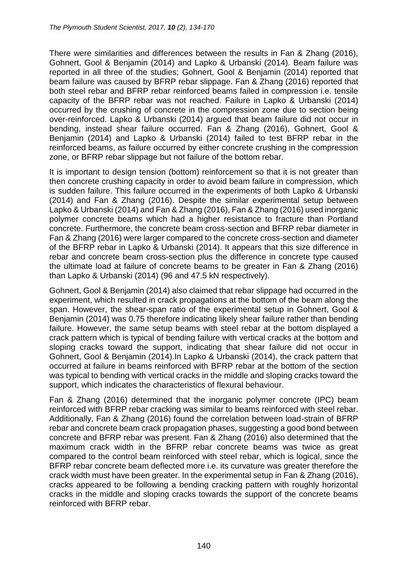
4.4 Beam B3 – bottom basalt bars (not anchored ends) The experiment showed that beam 3 reached a maximum load of 85.642 kN (including the self-weight of transverse steel beam) with a corresponding deflection of 28.5mm. Graph 4 depicts B3 concrete beam’s behaviour when subjected to load under flexure.
Graph 4:Beam B3: Load against Extension.
0
10
20
30
40
50
60
70
80
90
100
0 1 2 3 4 5 6 7 8 9 10 11 12 13 14 15 16 17 18 19 20 21 22 23 24 25 26 27 28 29 30
Load
(kN
)
Deflection (mm)
Basalt B2 - Load against Extension
0
10
20
30
40
50
60
70
80
90
0 1 2 3 4 5 6 7 8 9 10 11 12 13 14 15 16 17 18 19 20 21 22 23 24 25 26 27 28 29 30
Load
(kN
)
Deflection (mm)
Basalt B3 - Load against Extension

The Plymouth Student Scientist, 2017, 10 (2), 134-170
152
4.5 Beam B4 – bottom basalt bars lapped with steel L bars It was found that beam 4 reached a maximum load of 80.549kN (including the self-weight of the steel transverse beam) with a corresponding deflection of 26.1mm. Graph 5 depicts concrete beam B4’s behaviour when subjected to load under flexure.
Graph 5:Beam B4: Load against Extension.
Table 1 below summarises the experimental and predicted failure load values using steel reinforcement design principles, that are outlined in the appendicesError! Reference source not found. and Error! Reference source not found..
Table 1:R.C Beam Experimental against Theoretical Ultimate Load.
BEAM LOAD (kN)
THEORETICAL LOAD (kN)
DIFFERENCE (kN)
PERCENTAGE DIFFERNCE (%)
B1 84.130 45.302 38.828 46.2 B2 97.926 87.135 10.791 11.0 B3 85.642 87.135 1.493 1.7
B4 80.549 87.135 6.586 7.6
Furthermore, Graph 6 summarises the load and deflection relationship obtained by the reinforced concrete beam tests.
0
10
20
30
40
50
60
70
80
90
0 1 2 3 4 5 6 7 8 9 10 11 12 13 14 15 16 17 18 19 20 21 22 23 24 25 26 27 28
Load
(kN
)
Deflection (mm)
Basalt B4 - Load against Extension

The Plymouth Student Scientist, 2017, 10 (2), 134-170
153
4.6 Comparison of all four beams’ behaviour
Graph 6:Comparison of All Four Beams: Load against Extension.
---- Beam B1
---- Beam B2
---- Beam B3
---- Beam B4
The Plymouth Student Scientist, 2017, 10 (2), 134-170
154
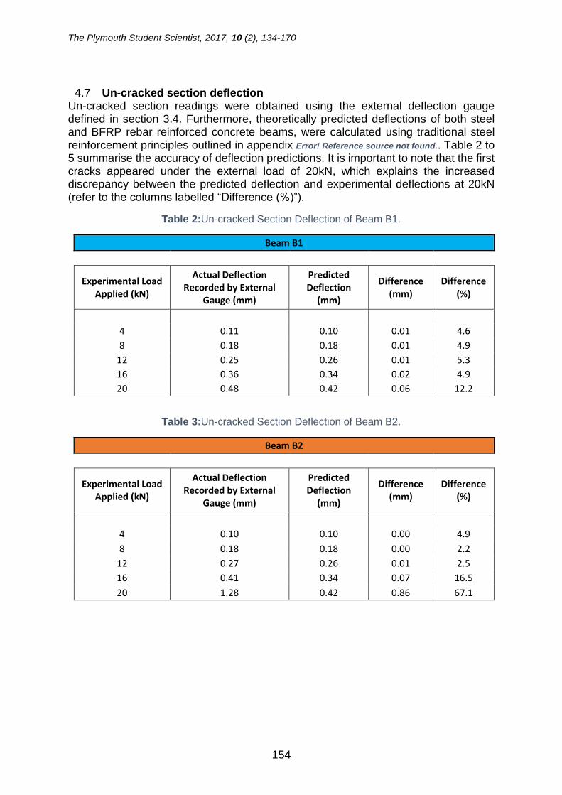
4.7 Un-cracked section deflection Un-cracked section readings were obtained using the external deflection gauge defined in section 3.4. Furthermore, theoretically predicted deflections of both steel and BFRP rebar reinforced concrete beams, were calculated using traditional steel reinforcement principles outlined in appendix Error! Reference source not found.. Table 2 to 5 summarise the accuracy of deflection predictions. It is important to note that the first cracks appeared under the external load of 20kN, which explains the increased discrepancy between the predicted deflection and experimental deflections at 20kN (refer to the columns labelled “Difference (%)”).
Table 2:Un-cracked Section Deflection of Beam B1.
Beam B1
Experimental Load Applied (kN)
Actual Deflection Recorded by External
Gauge (mm)
Predicted Deflection
(mm)
Difference (mm)
Difference (%)
4 0.11 0.10 0.01 4.6
8 0.18 0.18 0.01 4.9
12 0.25 0.26 0.01 5.3 16 0.36 0.34 0.02 4.9
20 0.48 0.42 0.06 12.2
Table 3:Un-cracked Section Deflection of Beam B2.
Beam B2
Experimental Load Applied (kN)
Actual Deflection Recorded by External
Gauge (mm)
Predicted Deflection
(mm)
Difference (mm)
Difference (%)
4 0.10 0.10 0.00 4.9
8 0.18 0.18 0.00 2.2
12 0.27 0.26 0.01 2.5
16 0.41 0.34 0.07 16.5
20 1.28 0.42 0.86 67.1

The Plymouth Student Scientist, 2017, 10 (2), 134-170
155
Table 4:Un-cracked Section Deflection of Beam B3.
Beam B3
Experimental Load Applied (kN)
Actual Deflection Recorded by External
Gauge (mm)
Predicted Deflection
(mm)
Difference (mm)
Difference (%)
4 0.10 0.10 0.00 4.9
8 0.18 0.18 0.00 2.2
12 0.26 0.26 0.00 1.2
16 0.36 0.34 0.02 4.9
20 0.50 0.42 0.08 15.7
Table 5:Un-cracked Section Deflection of Beam B4.
Beam B4
Experimental Load Applied (kN)
Actual Deflection Recorded by External
Gauge (mm)
Predicted Deflection
(mm)
Difference (mm)
Difference (%)
4 0.10 0.10 0.00 4.9
8 0.17 0.18 0.01 5.2
12 0.26 0.26 0.00 1.2
16 0.36 0.34 0.02 4.9
20 0.50 0.42 0.08 15.7
4.8 Cracked section deflection The deflections at failure point were recorded and compared with predicted deflections obtained using cracked section deflection estimation principles presented in the appendixError! Reference source not found.. It is important to mention that deflection due to shrinkage was omitted when calculating the ultimate failure deflection, since all tested beams were cast in the controlled environment. Additionally, beams were tested after a 28-50 day period had occurred when the beams were cast and subjected to an external load for a maximum of 45 minutes. Therefore, deflection due to shrinkage prediction was deemed not applicable when predicting maximum cracked section concrete beam deflection.

The Plymouth Student Scientist, 2017, 10 (2), 134-170
156
Table 6:Cracked Section Deflection at Failure.
Beam Predicted Deflection (mm)
Experimental Deflection (mm)
Difference (mm)
Difference (%)
B1 N/A N/A N/A N/A B2 31.0 27.9 3.0 9.8 B3 31.0 28.5 2.5 8.0 B4 31.0 26.1 4.9 15.7
5. Visual inspection
5.1 Beam B1 (control beam) Concrete removal from the bottom face of the concrete beam reinforced using 100% steel reinforcement, showed that no significant slippage occurred. Further to that, bar yielding was clearly visible. Photo 7 illustrates the appearance of tension in the longitudinal steel rebar after undergoing a yielding stage.
Photo 7:Beam B1 Yielded Tension Steel Bars.

The Plymouth Student Scientist, 2017, 10 (2), 134-170
157
5.2 BFRP rebar reinforced concrete beam B2 After the completion of the beam testing stage, the concrete was removed from the top and bottom faces of the concrete beams to carry out a visual inspection and investigate the slippage phenomenon. Firstly, it was observed that the basalt rebar experienced deboning of the spiral strands which act as ribs to increase the mechanical key between basalt rebar and concrete. Photo 8 illustrates the observed basalt rebar deboning phenomenon.
Photo 8:Basalt B2: basalt spiral strands are deboning from longitudinal strands.
Further investigation revealed that one out of two longitudinal BFRP tension reinforcing bars “snapped”. However, the second rebar did not “snap”. Instead it went through significant elongation as illustrated in Photo 9 and Photo 11.
Photo 9:Bottom basalt rebar elongated.
Finally, full concrete removal from the bottom face showed that no significant slippage occurred, that could be detected by visual inspection, as illustrated in Photo 10.

The Plymouth Student Scientist, 2017, 10 (2), 134-170
158
Photo 10:Basalt B2: bottom face of the beam.
Photo 11:BFRP Rebar Reinforced Concrete Beam B2: Reinforcement Failure.
5.3 BFRP rebar reinforced concrete beam B3 The same procedure of visual inspection was carried out for basalt beam B3 and it was observed that one bottom bar “snapped” at the conjunction with the steel shear link as illustrated in Photo 12.

The Plymouth Student Scientist, 2017, 10 (2), 134-170
159
Photo 12:Beam B3 Reinforcement Failure.
5.4 BFRP rebar reinforced concrete beam B4 Visual inspection showed that the both BFRP tension bars “snapped” in beam B4. Failure of the basalt beams occurred at the “shear crack” propagation point. The failed basalt bars did not exhibit significant elongation before failure as opposed to beam 2 as outlined in section 4.3.
Photo 13:Beam B4 Reinforcement Failure.
6. Discussion
6.1 Tensile test Constructability issues were experienced during the direct tensile test experiments. Firstly, when a plain basalt rebar was placed inside the testing machine and the maximum tensile strength was attempted to be obtained, the experiment was brought to a halt as the rebar slipped out from the testing machine clamps. Subsequent visual inspection showed that the basalt strands wrapped around the main longitudinal
V-SHAPE LIFTING BARS

The Plymouth Student Scientist, 2017, 10 (2), 134-170
160
strands in a spiral and serving as “ribs” simply sheared off (refer to Error! Reference source not found. attached in appendixError! Reference source not found.). Furthermore, BFRP spiral “ribs” significantly reduced the “grip area” of the basalt rebar placed inside the machine clamps.
During the second attempt to increase the surface grip area, two aluminium rods were attached to each end of the basalt rebar sample. Holes with a 10mm diameter were drilled and the inside faces of the walls of the aluminium rods were threaded to increase the mechanical key between the BFRP rebar and the aluminium rod. Subsequently each end of the basalt rebar sample was placed inside the aluminium rods and set with resin and adhesive. During the tensile testing stage the basalt rebar pulled out of the aluminium rods before it reached its maximum tensile capacity. It was concluded that failure occurred due to the resin shear resistance being significantly smaller than the tension force applied by the testing machine (refer to Error! Reference source not found. in appendix Error! Reference source not found.). Gohnert, Gool & Benjamin (2014) claimed that by encasing both ends in tight fitting tubes, the maximum tensile capacity of BFRP rebar was achieved. Therefore, it is arguable that Gohnert, Gool & Benjamin (2014) in his study used specifically high shear resistance resin when undertaking tensile tests. In addition to that, when visually inspecting aluminium rods it was observed that they did not deform. Thus, this suggest that the aluminium rod wall could be too thick and therefore did not transfer the “grip” to the BFRP rebar (refer to Photo 1).
Moreover, it was attempted to “sand off” the BFRP spiral at each end as illustrated in Photo 2. Once again the experiment failed to test BFRP rebar maximum tensile capacity as one end of the rebar came out of the testing machine clamps. During the visual inspection, it was observed that the “teeth” of the upper clamp were partly damaged. Error! Reference source not found. attached in appendix Error! Reference source not found. illustrates the damaged “teeth” condition. Additionally, when the smaller size clamps were used, the failure of the test was caused by the BFRP rebar sample crushing inside the clamps (refer to Error! Reference source not found. attached in appendix Error! Reference source not found.). Due to brittle nature of fibre binding resin, it was not able to withstand the force in the lateral direction.
Lastly, Fan & Zhang (2016) claimed that the BFRP rebar reinforcement and concrete bonded well. Therefore, in this study it was proposed to embed the BFRP reinforcement rebar in the concrete cube and undertake the BFRP rebar tensile strength test in a form of pulling rebar out of the concrete cube. Unfortunately, the test was unsuccessful due to the upper end of the basalt rebar sample pulling out from the testing machine clamps. However, the results of the pull-out test undertaken, reinforces the claim of a strong bond between BFRP rebar and concrete that was made in the study by Fan & Zhang (2016), as the BFRP rebar was not pulled out from the concrete cube.
6.2 Constructability Several buildability issues have arisen during the concrete beam reinforcement assembly stage. Initially it was proposed to use BFRP shear links and L bars. However, after contacting several manufacturers, it emerged that a considerable number of elements needed to be ordered, which was far outside of the project budget. Therefore, traditional shear links and L bars were utilised. The ordering issues outlined above suggest that this potentially prevents basalt development adoption for small

The Plymouth Student Scientist, 2017, 10 (2), 134-170
161
scale projects, where a small amount reinforcement would be required. In order for BFRP rebar reinforcement to be adopted, improvement is required in production phases allowing a manufacturer to supply small amounts of reinforcement elements.
The tensile test has proved that there are clear constructability and handling issues of the BFRP rebar reinforcement (refer to section 6.1). In order for BFRP rebar reinforcement to be adopted, stronger or more flexible binding to the basalt fibres resin would need to be developed in order to facilitate the testing procedure of the BFRP reinforcement.
Furthermore, for adoption of the basalt reinforcement to occur, it is fair to suggest that development of the reinforcement elements joining system would facilitate the construction process. For example, a rebar coupling system would allow for assembly of shear links, L-bars or U-bars to take place on a construction site. Currently it is impossible to manually bend longitudinal BFRP bars to make it into L-bars, U-bars or shear links.
6.3 Results
6.3.1 Control beam (B1) Failure load summary in Table 1 shows significant difference between beam B1 theoretical and experimental failure load values. Traditional steel reinforcement design principles outlined in the appendix Error! Reference source not found. calculates the failure load up to the plastic limit when steel bars start to yield. This explains the experimental failure load being over 46% higher than predicted. When tension bar reinforcement reached plastic behaviour, it was still able to accommodate increase in load by the means of yielding (refer to Figure 5).
Figure 5: Steel Bar Yielding.

The Plymouth Student Scientist, 2017, 10 (2), 134-170
162
6.3.2 Un-cracked section It is evident from Graph 6 that concrete beam concrete mix has been consistent since the initial gradient of load- deflection graphs up to around 20kN are almost identical. This suggests that the BFRP rebar reinforced un-cracked section concrete beams behaved virtually identical to traditional steel reinforced concrete beam when the section was un-cracked.
Moreover, it is evident that theoretical deflection predictions of BFRP rebar reinforced concrete beams based on traditional steel reinforcement design principles are consistent and sufficiently accurate. Results in section 4.7 show that up to when the first crack appeared (under the load of 20 kN plus self-weight of steel transverse beam), the difference between observed and predicted deflection of BFRP rebar reinforced beams differed by approximately 5%. However, when testing the beam B2, the greater difference between the actual and the predicted deflection values emerged under the load of 16kN (plus self-weight of the steel transverse beam). This can be explained by the fact that with the progression of time after around a14-day period of concrete beam casting, the concrete elastic modulus to decreases and therefore beam becomes slightly less elastic and cracks start to appear earlier (Neville, Brooks, 2010). Concrete beam B2 was tested after 50 days from the casting date as opposed to beams B2 to B4 which were tested at 28-days after casting. Therefore, it is fair to suggest that this could be the cause of slightly greater deflection of beam B2 in relation to other concrete beams.
6.3.3 Cracked section In contrast, it can be clearly seen that once the BFRP rebar reinforced beams are cracked, the behaviour in terms of load and displacement is fundamentally different. It appears from Graph 6 that the relationship between the cracked section load and displacement of the BFRP rebar reinforced concrete beams (B2, B3 and B4) is virtually linear, whereas the traditional steel reinforced concrete beam (B1) has a clearly visible yielding stage. This can be explained by the low value of BFRP rebar modulus of elasticity (refer to appendix Error! Reference source not found.), which is over 4 times lower than traditional steel rebar. Additionally, linear load and deflection relationship suggests that failure load should be easily predictable as opposed to the steel yielding stage.
Furthermore, there is a relatively small variation between the cracked section concrete beams reinforced with BFRP rebar as depicted in Graph 6.The ultimate load at which the beams failed varies from5.9%to 21.5%within the 3 BFRP rebar reinforced concrete beams and the displacement variation ranges between 2.0% and 8.4%. Nevertheless, based on the previously outlined percentage variation, the suggestion can be made that a materials factor should be introduced when designing reinforced concrete beams reinforced with BFRP rebar to account for the ultimate load and displacement variations.
Also, it was discovered that using traditional steel reinforcement design principles (refer to appendixError! Reference source not found.) failure load predicted were sufficiently accurate. Summary in Table 1 shows that theoretical and experimental failure load values vary from 1.7% to 11.0%. However, the experimental failure loads of the beams B3 and B4 were slightly lower than predictions outlined in Table 1. This suggests the presence of the statistical variation in reinforcement material and therefore it is fair to suggests that statistical factors need to be introduced when undertaking the design of the BFRP reinforcement.

The Plymouth Student Scientist, 2017, 10 (2), 134-170
163
Moreover, Graph 6 shows that BFRP rebar reinforced concrete beam B3 with free ends (no anchor) exhibited greater maximum deflection at failure compared with the other two concrete beams which are BFRP rebar reinforced and lapped with steel L bars. Current experimental data obtained suggests that anchoring of BFRP tension rebar reduces maximum deflection. On the other hand, although beam B3 displayed the highest vertical displacement at failure, the corresponding failure load was higher than beam B4 but lower than beam B2. In order to support the hypothesis that anchoring BFRP tension rebar reduces the deflection, more samples beams must to be tested in order to provide more credible and robust results. In addition to that, beam B4 lower ultimate failure load being lower than beam B3 could be dictated by the BFRP tension bars being damaged by the steel L bars, observed during the visual inspection (refer to section 6.4.4).
Table 6 show that the BFRP rebar reinforced concrete beams predicted deflection are sufficiently accurate. Further to that, predicted values are slightly overestimated compared to the experimental values. Theoretical deflections are higher than experimental ones in a range of 9.8% to 15.7% (refer to Table 6). This suggests that traditional steel reinforcement principles are safely suitable for designing BFRP reinforcement in terms of cracked section deflections as predicted values are “on the safe side” and sufficiently close to the actual deflections.
Imperfection of support conditions must be taken into account. The theoretical calculations that were used to obtain the predicted ultimate load capacity assumes a concrete beam with pin and roller support conditions. However, the experimental supports do not entirely represent pin and roller support conditions. Instead it partly acts as two pin support condition system. This arguably could contribute to the difference between theoretical predictions and experimental ultimate load capacity results.
Also, it is important to mention, that marginal deflection induced due to deflection of transverse steel beam was omitted during the analysis, as the deflection caused by it was only 0.03mm and therefore deemed insignificant. Refer to appendix Error! Reference source not found. for deflection analysis of the transverse beam.
6.4 Visual inspection
6.4.1 Beam B1 Beam bending tests showed that the concrete beam (B1) reinforced with 100% traditional steel reinforcement (refer to Figure 4), experienced compression failure as illustrated in Photo 6. This can be explained by the fact that once the concrete beam cracks, the neutral axis shifts higher towards the top of the concrete beam section. As this progresses further, the top area withstanding compression generated by the external load, reduces until the concrete’s compressive strength becomes lower than compressive force generated on to the beam by application of an external load. This causes concrete to spall from the top of the concrete beam and the beam to fail. Figure 6 depicts the compression area reduction in reinforced concrete beam. Furthermore, the compression failure (refer to Photo 6) occurred prior to steel bottom tension bar “snapping”. (refer to Photo 7).

The Plymouth Student Scientist, 2017, 10 (2), 134-170
164
Figure 6: Neutral Axis Shifts Up as Cracking Progresses.
6.4.2 Beam B2 It is important to address the fact that one of the basalt longitudinal bar underwent significant elongation only at the point of failure as depicted in Photo 9. It was initially assumed that the slippage of the BFRP rebar (located at the tension zone) occurred. The slippage phenomenon means that the BFRP rebar is moving irrespective of the concrete surrounding the rebar. However, subsequent full exposure of bottom basalt longitudinal bars showed that slippage did not occur that could be detected by a visual inspection, as there was no evidence of rebar slipping. This suggests that once the first basalt bottom longitudinal bar “snapped” full load applied by the experimental machinery was transferred onto the second basalt bottom rebar. At this point rebar was carrying the load which was twice the load the rebar was designed to carry. This dramatic elongation can be explained by the high Poisson’s ratio. It was established by Gohnert, Gool & Benjamin (2014) that Poisson’s ratio is approximately 4 (subject to variation depending on manufacturer) as opposed to steel with ration of 0.25-0.3. This means that basalt reinforcement can go through significant elongation which results in reduction of the cross-sectional area compared to traditional steel reinforcing rebar.
Furthermore, it is evident from Photo 11 that the failure of the BFRP rebar occurred at the conjunction with the steel shear links. This suggests that steel shear links could have caused the failure of BFRP rebar. Based on the evidence currently available, it seems fair to suggest that steel shear links were forced to move up when the concrete beam was subjected to an external load and therefore exhibited deflection by curvature. This could have caused local stresses to concentrate onto the BFRP longitudinal rebar at the junction with the steel shear links.
In addition to that, Photo 11 depicts that the second bottom longitudinal BFRP rebar was not far from its breaking point. It can be seen in Photo 11 that the BFRP rebar that underwent significant elongation, started to break at the location very close to the shear link. Also, it is visible from Photo 11 that the BFRP rebar fibres are starting to break. Additionally, it is visible that resin which bonds the basalt fibres in the rebar changed colour, which indicated the failure of the resin.
6.4.3 Beam B3 Similar results were observed when BFRP rebar reinforcement was exposed. Photo 12 shows that only one BFRP tension rebar “snapped”. BFRP rebar failure occurred at the conjunction with the steel shear link, suggesting the failure was caused by the steel shear link.

The Plymouth Student Scientist, 2017, 10 (2), 134-170
165
6.4.4 Beam B4 During the visual inspection of the beam B4 (refer to section5.4) it was observed that both BFRP tension bars “snapped”. Interestingly the basalt bars failed at the exact location where the steel L bars end when lapped with BFRP tension bars (refer to Photo 13). This suggests that during the period when beam was subjected to external load the concrete beam curvature increased forcing the steel L bars down, resulting in steel L bars contributing to failure of BFRP longitudinal bars by causing localised stresses. Further to that, bending moment and shear capacity checks outlined in appendix Error! Reference source not found. suggest that concrete beam B4 was more than capable to withstand the forces applied at the point of failure. The analysis undertaken at the location of the failure showed, that area of tension reinforcement required to withstand the subjected forces was 68mm2. Two 8mm diameter BFRP bars provided 101mm2 area of reinforcement. This signifies that reinforcement failure at the location of concrete beam failure was not caused by bending. Furthermore, shear check outlined in appendix Error! Reference source not found. also suggests that failure was not caused by the failing shear links. Shear force applied required minimum of 30 mm2, whereas steel shear links used provided area of 151mm2. The area of reinforcement that the shear links provided was over three times more than required.
6.4.5 Summary of visual inspection Firstly, observations made by means of visual inspection suggest that none of the BFRP rebar reinforced concrete beams were affected by the rebar slippage phenomenon, as BFRP rebar experienced elongation and spiral de-bonding only at the point of shear failure. Furthermore, emphasis must be put on the distinct difference in failure modes between beams reinforced with BFRP rebar and traditional steel rebar. Although the reinforcement setting-out was virtually identical for both, steel and BFRP rebar reinforced concrete beams, the control beam B1 failed in compression and all other BFRP reinforced concrete beams failed in shear. This was dictated by the BFRP rebar higher tensile strength. Analysis undertaken in appendix Error! Reference source not found. and Error! Reference source not found. show that the neutral axis position of the beam B1 was calculated to be 15mm from the top of the section. The neutral axis of the BFRP reinforced beams was calculated to be 30mm from the top of the section. It was established earlier that with the advancement of the cracking, the neutral axis moves upward towards the top of the section (refer to 6.4.1). The lower position of the neutral axis of the BFRP reinforced concrete beam allowed for greater compression resistance under the same strength class concrete. Thus, the shear failure occurred before beam failed in compression.
The different failure cases discussed above suggest that there is a limitation in creating hybrid reinforcing systems consisting of traditional steel and BFRP rebar elements. Since BFRP rebar is inherently softer due to fibre binding resin compared to steel, it is only logical that it will be damaged by a lot harder traditional steel components. However, it is obvious that the BFRP rebar failure caused by the damage of steel reinforcement elements, occurred during the plastic stage when the reinforced concrete beams were close to its failure point. On one hand, it is fair to suggest that in reality such a phenomenon would not be critical since BFRP and steel hybrid reinforced concrete beams would be designed to perform elastically with no cracks present. On the other hand, this phenomenon would have a huge significance in the case of critical structural damaging events such as accidental explosion, earthquake or terrorist attacks. Therefore, it is important to design out different BFRP and steel

The Plymouth Student Scientist, 2017, 10 (2), 134-170
166
reinforcement detailing clashes to ensure the provision of sufficient time allowance for residents to safely leave failing structure.
Ultimately, it is important to note that shear failure in BFRP rebar reinforced concrete beams occurred at one end only (refer to Photo 6). This could be caused by marginally different reinforcement position at each end of the beam. It is possible that reinforcement could have dislocated from its original position during the beam casting stage when a vibrating poker was used. In addition, that marginal difference in shear link spacing, during the reinforcement cage assembly phase could have contributed to the unsymmetrical reinforcement setup. Furthermore, the analysis carried out suggests, that the shear span of the tested beams was 1.8, as depicted in Figure 7. This suggests that the shear span ration was too low and potentially resulted in shear failure BFRP rebar reinforced beams as illustrated in Photo 6. Naik & Kute (2014) suggested that, that to prevent shear failure, shear span to depth ratio should be greater than 2.5.
Figure 7: Shear Span Ratio of the Reinforced Concrete Beams.
6.5 Real-life situation representation It is important to note that in typical construction, shear links would be spaced out throughout the full span of a concrete beam. In this study shear links in the middle region were omitted purely to make sure that BFRP reinforcement is tested in bending.
7. Conclusions Results obtained during this study suggest there is promising potential for BFRP rebar reinforcement to replace traditional steel reinforcement, or at least to be incorporated as a hybrid system. The behaviour of the un-cracked section of the BFRP rebar reinforced concrete beam was shown to match the behaviour of the traditional steel reinforced beam in this experiment. The steel reinforcement design principles accurately predicted the un-cracked section of the BFRP rebar reinforced concrete

The Plymouth Student Scientist, 2017, 10 (2), 134-170
167
beam deflection. Furthermore, the crack propagation of the BFRP rebar reinforced concrete beam was virtually identical to the traditional steel reinforced concrete beams.
Secondly referring to the cracked sections of the concrete beams, this study determined that the behaviour of the cracked section of the BFRP rebar reinforced concrete beam was completely different to a traditional steel reinforced concrete beam. The results showed that the cracked section of the BFRP reinforced concrete beams displayed linear load and vertical displacement relationship without a clearly visible yielding stage. Additionally, it was found that BFRP rebar reinforced concrete beams deflected nearly twice as much than the traditional steel reinforced concrete beam. Nevertheless, loads at failure of BFRP reinforced concrete beams were higher than the traditional steel reinforced concrete beam and the steel reinforcement design principles predicted failure load and displacement to a sufficient degree of accuracy.
Furthermore, this study did not find any evidence of BFRP rebar slippage phenomenon occurring. Also, current experimental results suggested that anchoring each end of BFRP rebar reduced ultimate failure deflection of the BFRP rebar reinforced concrete beams. Nevertheless, reduced deflection was marginal and therefore more experimental investigation is required to strengthen current findings. Finally, it was concluded that the detailing issues must be carefully taken into consideration when using a hybrid steel and BFRP rebar reinforcement to ensure that the premature failure of the BFRP rebar does not occur.
8. Future work improvements The following work improvements are suggested to refine the experiment conducted in this study, to improve the flexural behaviour of BFRP rebar reinforced concrete beams.
First to mention, due to the unsuccessful tensile strength experiment, the BFRP rebar tensile strength was chosen based on results produced by other studies (refer to section 6.1). Therefore, to try and achieve a successful tensile strength experiment, a more refined BFRP rebar tensile strength experiment needs to be carried out using thinner encasement tubes and higher shear resistance resin. Additionally, review of the comparison of the theoretical predictions and experimental deflections and ultimate failure loads need to be carried out.
To increase credibility and production of more robust test results a higher number of BFRP rebar reinforced concrete beams samples should be tested. The current analysis and the discrepancy between different setup failure modes does not reflect statistical variation.
It was clear that shear span ratio in this experiment was too low (refer to Figure). This means that future improvements could be made by placing the load transfer rollers closer together and increasing the spacing between the shear links or adding a greater number of shear links to the reinforcement cage. This would reduce the middle region span where no shear links were present and therefore increase the shear span ratio, potentially avoiding shear failure. Alternatively, the shear span to depth ratio could be reduced by making a less deeper section. However, this would be extremely complicated due to the very small spacing of the reinforcement elements.
The Plymouth Student Scientist, 2017, 10 (2), 134-170
168
Another improvement to this study would be to incorporate the shear links and L bars that are made of BFRP rebar. It would be interesting to see if tension BFRP bars failure would be affected by the clash with the BFRP shear link and L bars.
To avoid the failure of BFRP rebar described in section 6.4.4, further improvement could be made by placing steel L bars to the side of the BFRP longitudinal tensions bars (refer to Figure 8).

The Plymouth Student Scientist, 2017, 10 (2), 134-170
169
Figure 8: Steel L-Bar Location.
One of the most significant drawbacks of the BFRP rebar reinforcement is excessive deflection caused by low elastic modulus of elasticity of BFRP rebar. Further improvement on beam flexural behaviour could be undertaken by applying external fibre reinforced polymer (FRP) fabric wrapping techniques. A study undertaken by Sen & Reddy (2013) showed that using external FRP jute glass and carbon fabric wrapping techniques helped to reduce the reinforced concrete beam deflection. Basalt fibre reinforced polymer fabric could be applied to reduce the deflection of BFRP rebar reinforced concrete beam.
As the literature review revealed that the resistance of BFRP rebar to heat is significantly higher than traditional steel rebar, an additional step to this study could be subjecting BFRP and traditional steel rebar reinforced beams to heat and external loading at the same time to compare the difference in behaviour.
Moreover, it was established in this study that cracks in BFRP rebar reinforced concrete beams propagate virtually the same way as in traditional steel reinforced beams. To strengthen the existing findings of this study, an assessment could be carried out to determine whether traditional steel reinforced concrete beam crack width prediction theory is applicable to BFRP reinforcement system.
Finally, an internal strain gauge attached to the BFRP rebar during cage assembly stage would be useful, to observe the actual strain of BFRP rebar inside the concrete beam and compare it with the strain obtained during the maximum tensile strength experiment.
Acknowledgements Firstly, I would like to thank Mr J. (Hans) De Wit, the owner and CEO of “VULKAN” based in the Netherlands, for providing the reinforcement materials and related information required for this project. The Basalt reinforced polymer rebar was essential for carrying out this project, so I am deeply appreciative of this voluntary contribution.

The Plymouth Student Scientist, 2017, 10 (2), 134-170
170
Also, I want to thank my dissertation supervisor Mr David Easterbrook for the excellent guidance and support he provided throughout my dissertation project.
Finally, I would like to thank the Brunel Laboratory technician Mr Trevor Bevan and the lecturer Mr Tony Tapp for their continuous support in the heavy structures laboratory during the experimental stage of this project.
9. Reference List American Concrete Institute Committee 440. (2006) ‘Commercially available FRP reinforcing rebars’, 440.1R-06: Guide for the Design and Construction of Structural Concrete Reinforced with FRP Rebars, [Online] Available at: https://www.concrete.org/store/productdetail.aspx?ItemID=440106&Format=DOWNLOAD
Dhand, V., Mittal., G., Rhee, K.Y., Park, S-J. & Hui, D. (2015) ‘A Short Review on BFRP Fiber Reinforced Polymer Composites’, Composites Part B,73, pp. 166-180.
Fan, X & Zhang, (2016) ‘Experimental Study on Flexure Behaviour of Inorganic Polymer Concrete Beams Reinforced with BFRP rebar’, Composites Part B,93, pp. 174-183.
Fiore, V., Scalici, T., Di Bella, G. Valenza, A. (2015) ‘A Review on BFRP Fibre and its Composites’, Composites Part B, 74, pp. 74-94.
Ge, W., Zhang, J., Cao, D & Tu, Y. (2015) Flexural Behaviours of Hybrid Concrete Beams Reinforced with BFRP Rebars and Steel Rebars. Construction and Building Materials, 87, pp. 28-37.
Gohnert, M., Van Gool, R. & Benjamin, M. (2014) ‘BFRP reinforced in concrete beams in flexure’, The Structural Engineer, pp. 38-43.
Juenger, M.C.G. & Siddique, R. (2015) Recent Advances in Understanding the Role of Supplementary Cementitious Materials in Concrete. Cement and Concrete Research, 78, pp. 71-80.
Lapko, A.& Urbanski, M. (2014) ‘Experimental and Theoretical Analysis of Deflections of Concrete Beams Reinforced with BFRP rebar’ Archives of Civil and Mechanical Engineering,15, pp.223-230.
Mosley B., Bungey J. & Hulse R. (2007) Reinforced Concrete Design to Eurocode 2. 6th edn. Basingstoke: Palgrave Macmillan, pp 136-145. Neville A.M., Brooks J.J. (2010) Concrete Technology. 2nd edn. Harlow: Pearson Education Limited, pp 206-212.
Pears, R. & Shields, G. (2008) Cite Them Right The Essential Referencing Guide. 3rd edn. Newcastle upon Tyne: Pear Tree Books.
Ross, A. (2006) ‘BFRP Fibers: Alternative To Glass?’ Composites World, [Online]. Available at: http://www.compositesworld.com/articles/BFRP-fibers-alternative-to-glass (Accessed: 10 December 2016)
Shafiq, N., Ayub, T., & Khan, S.U. (2016) Investigating the Performance of PVA and BFRP Fibre Reinforced Beams Subjected to Flexural Action. Composite Structures, 153, pp. 30-41.

The Plymouth Student Scientist, 2017, 10 (2), 134-170
171
Sim, S., Park, C. & Moon, D.Y. (2005) Characteristics of Basalt Fiber as a Strengthening Material for Concrete Structures. Composites Part B, 36, pp. 504-512.
Tara Sen, H. N. Jagannatha Reddy (2013) ‘Strengthening of RC beams in flexure using natural jute fibre textile composite system and its comparative study with CFRP and GFRP strengthening systems’, International Journal of Sustainable Built Environment, Vol 2, pp 41-55.
Teychenne, D. C., Franklin, R. E., Erntroy, H. C. (1997) Design of Normal Concrete Mixes. 2nd edn. Building Research Establishment Ltd: Garston. pp 10-22.
U.P. Naik, S. Y. Kute (2014) ‘Effect of Shear Span to Depth Ration on Shear Strength of Steel Fiber Reinforced High Strength Concrete Deep Beam using ANN’, International Journal of Engineering Research & Technology (IJERT), Vol. 3 Issue 6, June 2014, pp 927-930.
Urbanski, M., Lapko, A. & Garbacz, A. (2013) ‘Investigation on Concrete Beams Reinforced with Basalt Rebars as an Alternative of Conventional R/C Structures’ Procedia Engineering,57, pp.1183-1191.
Zhu, H., Wu, G., Zhang, L., Zhang, J. & Hui, D. (2014) Experimental Study on the Fire Resistance of RC beams Strengthened with near-surface-mounted high-Tg BFRP Rebars. Composites Part B – Eng,60, pp. 680-687.
Appendices can be seen in Supplementary files in the list of Article Tools showing
to the right-hand side of the main window.