Embed Size (px)
Citation preview

Reg
iste
red
copy
for
joha
nnes
.ple
tzer
@cs
.uni
-sal
zbur
g.at
FlexRay Communications System
Protocol Specification
Version 2.1Revision A
2.1 Revision A

FlexRay Protocol Specification Disclaimer
Reg
iste
red
copy
for
joha
nnes
.ple
tzer
@cs
.uni
-sal
zbur
g.at
Disclaimer
This specification as released by the FlexRay Consortium is intended for the purpose of information only.The use of material contained in this specification requires membership within the FlexRay Consortium oran agreement with the FlexRay Consortium. The FlexRay Consortium will not be liable for any unauthorizeduse of this Specification.
Following the completion of the development of the FlexRay Communications System Specificationscommercial exploitation licenses will be made available to End Users by way of an End User's LicenseAgreement. Such licenses shall be contingent upon End Users granting reciprocal licenses to all CorePartners and non-assertions in favor of all Premium Associate Members, Associate Members and Devel-opment Members.
All details and mechanisms concerning the bus guardian concept are defined in the FlexRay Bus GuardianSpecifications.
The FlexRay Communications System is currently specified for a baud rate of 10 Mbit/s. It may be extendedto additional baud rates.
No part of this publication may be reproduced or utilized in any form or by any means, electronic ormechanical, including photocopying and microfilm, without permission in writing from the publisher.
The word FlexRay and the FlexRay logo are registered trademarks.
Copyright © 2004-2005 FlexRay Consortium. All rights reserved.
The Core Partners of the FlexRay Consortium are BMW AG, DaimlerChrysler AG, Freescale HalbleiterDeutschland GmbH, General Motors Corporation, Philips GmbH, Robert Bosch GmbH, and VolkswagenAG.
Version 2.1 Revision A 22-December-2005 Page 2 of 245
FlexRay Protocol Specification Table of Contents
Table of Contents
Reg
iste
red
copy
for
joha
nnes
.ple
tzer
@cs
.uni
-sal
zbur
g.at
Chapter 1
Introduction.............................................................................................................. 10 1.1 Scope .............................................................................................................................................10 1.2 References .....................................................................................................................................10 1.2.1 FlexRay consortium documents ........................................................................................... 10 1.2.2 Non-consortium documents.................................................................................................. 10 1.3 Revision history ..............................................................................................................................12 1.4 Terms and definitions .....................................................................................................................13 1.5 Acronyms and abbreviations ..........................................................................................................16 1.6 Notational conventions ...................................................................................................................18 1.6.1 Parameter prefix conventions............................................................................................... 18 1.6.2 Color coding ......................................................................................................................... 18 1.7 SDL conventions ............................................................................................................................19 1.7.1 General................................................................................................................................. 19 1.7.2 SDL Notational Conventions ................................................................................................ 19 1.7.3 SDL Extensions .................................................................................................................... 20 1.7.3.1 Microtick, macrotick and sample tick timers ................................................................. 20 1.7.3.2 Microtick behavior of the 'now' - expression ................................................................. 20 1.7.3.3 Channel-specific process replication ............................................................................ 21 1.7.3.4 Handling of Priority Input Symbols ............................................................................... 21 1.8 Network topology considerations....................................................................................................21 1.8.1 Passive bus topology............................................................................................................ 22 1.8.2 Active star topology .............................................................................................................. 22 1.8.3 Active star topology combined with a passive bus topology................................................. 24 1.9 Example node architecture.............................................................................................................25 1.9.1 Objective............................................................................................................................... 25 1.9.2 Overview............................................................................................................................... 25 1.9.3 Host - communication controller interface ............................................................................ 26 1.9.4 Communication controller - bus driver interface ................................................................... 26 1.9.5 Bus driver - host interface..................................................................................................... 27 1.9.5.1 Hard wired signals (option A) ....................................................................................... 27 1.9.5.2 Serial Peripheral Interface (SPI) (option B) .................................................................. 27 1.9.6 Bus driver - power supply interface (optional) ...................................................................... 28 1.10 Testability Requirements ..............................................................................................................28
Chapter 2Protocol Operation Control .................................................................................... 29
2.1 Principles ........................................................................................................................................29 2.1.1 Communication controller power moding ............................................................................. 29 2.2 Description......................................................................................................................................31 2.2.1 Operational overview............................................................................................................ 32 2.2.1.1 Host commands............................................................................................................ 33 2.2.1.2 Error conditions ............................................................................................................ 33 2.2.1.2.1 Errors causing immediate entry to the POC:halt state ..........................................33 2.2.1.2.2 Errors handled by the degradation model .............................................................34 2.2.1.3 POC status ................................................................................................................... 34 2.2.1.4 SDL considerations for single channel nodes .............................................................. 36 2.3 The Protocol Operation Control process ........................................................................................36 2.3.1 POC SDL utilities.................................................................................................................. 37
Version 2.1 Revision A 15-December-2005 Page 3 of 245
FlexRay Protocol Specification Table of Contents
Reg
iste
red
copy
for
joha
nnes
.ple
tzer
@cs
.uni
-sal
zbur
g.at
2.3.2 SDL organization .................................................................................................................. 38 2.3.3 Preempting commands......................................................................................................... 39 2.3.4 Reaching the POC:ready state............................................................................................. 40 2.3.5 Reaching the POC:normal active state ................................................................................ 41 2.3.5.1 Wakeup and startup support ........................................................................................ 43 2.3.6 Behavior during normal operation ........................................................................................ 45 2.3.6.1 Asynchronous commands ............................................................................................ 45 2.3.6.2 Cyclical behavior .......................................................................................................... 45 2.3.6.2.1 Cycle counter.........................................................................................................46 2.3.6.2.2 POC:normal active state........................................................................................46 2.3.6.2.3 POC:normal passive state.....................................................................................47 2.3.6.2.4 Error checking during normal operation ................................................................49 2.3.6.2.4.1 Error checking overview ................................................................................50 2.3.6.2.4.2 Error checking details for the POC:normal active state.................................50 2.3.6.2.4.3 Error checking details for the POC:normal passive state ..............................51
Chapter 3Coding and Decoding ............................................................................................. 54
3.1 Principles ........................................................................................................................................54 3.2 Description......................................................................................................................................54 3.2.1 Frame and symbol encoding ................................................................................................ 55 3.2.1.1 Frame encoding............................................................................................................ 56 3.2.1.1.1 Transmission start sequence.................................................................................56 3.2.1.1.2 Frame start sequence............................................................................................56 3.2.1.1.3 Byte start sequence...............................................................................................56 3.2.1.1.4 Frame end sequence.............................................................................................56 3.2.1.1.5 Dynamic trailing sequence ....................................................................................56 3.2.1.1.6 Frame bit stream assembly ...................................................................................57 3.2.1.2 Symbol encoding .......................................................................................................... 58 3.2.1.2.1 Collision avoidance symbol and media access test symbol ..................................58 3.2.1.2.2 Wakeup symbol .....................................................................................................59 3.2.2 Sampling and majority voting ............................................................................................... 61 3.2.3 Bit clock alignment and bit strobing ...................................................................................... 61 3.2.4 Channel idle detection .......................................................................................................... 63 3.2.5 Action point and time reference point ................................................................................... 63 3.2.6 Frame and symbol decoding ................................................................................................ 65 3.2.6.1 Frame decoding............................................................................................................ 66 3.2.6.2 Symbol decoding .......................................................................................................... 67 3.2.6.2.1 Collision avoidance symbol and media access test symbol decoding ..................67 3.2.6.2.2 Wakeup symbol decoding .....................................................................................67 3.2.6.3 Decoding error.............................................................................................................. 68 3.2.7 Signal integrity ...................................................................................................................... 68 3.3 Coding and decoding process ........................................................................................................69 3.3.1 Operating modes .................................................................................................................. 69 3.3.2 Coding and decoding process behavior ............................................................................... 69 3.3.3 Encoding behavior................................................................................................................ 71 3.3.4 Encoding macros.................................................................................................................. 73 3.3.5 Decoding behavior................................................................................................................ 77 3.3.6 Decoding macros.................................................................................................................. 78 3.4 Bit strobing process ........................................................................................................................85 3.4.1 Operating modes .................................................................................................................. 85 3.4.2 Bit strobing process behavior ............................................................................................... 86 3.5 Wakeup pattern decoding process .................................................................................................87
Version 2.1 Revision A 15-December-2005 Page 4 of 245
FlexRay Protocol Specification Table of Contents
Reg
iste
red
copy
for
joha
nnes
.ple
tzer
@cs
.uni
-sal
zbur
g.at
3.5.1 Operating modes .................................................................................................................. 87 3.5.2 Wakeup decoding process behavior .................................................................................... 88 3.5.3 Wakeup decoding macros .................................................................................................... 89
Chapter 4Frame Format........................................................................................................... 90
4.1 Overview.........................................................................................................................................90 4.2 FlexRay header segment (5 bytes) ................................................................................................90 4.2.1 Reserved bit (1 bit) ............................................................................................................... 90 4.2.2 Payload preamble indicator (1 bit) ........................................................................................ 91 4.2.3 Null frame indicator (1 bit) .................................................................................................... 91 4.2.4 Sync frame indicator (1 bit)................................................................................................... 91 4.2.5 Startup frame indicator (1 bit) ............................................................................................... 92 4.2.6 Frame ID (11 bits)................................................................................................................. 92 4.2.7 Payload length (7 bits).......................................................................................................... 93 4.2.8 Header CRC (11 bits) ........................................................................................................... 93 4.2.9 Cycle count (6 bits)............................................................................................................... 94 4.2.10 Formal header definition..................................................................................................... 94 4.3 FlexRay payload segment (0 - 254 bytes)......................................................................................94 4.3.1 NMVector (optional).............................................................................................................. 95 4.3.2 Message ID (optional, 16 bits).............................................................................................. 96 4.4 FlexRay trailer segment..................................................................................................................96 4.5 CRC calculation details ..................................................................................................................97 4.5.1 CRC calculation algorithm .................................................................................................... 97 4.5.2 Header CRC calculation ....................................................................................................... 98 4.5.3 Frame CRC calculation ........................................................................................................ 98
Chapter 5Media Access Control ........................................................................................... 100
5.1 Principles ......................................................................................................................................100 5.1.1 Communication cycle ......................................................................................................... 100 5.1.2 Communication cycle execution ......................................................................................... 101 5.1.3 Static segment.................................................................................................................... 102 5.1.3.1 Structure of the static segment................................................................................... 102 5.1.3.2 Execution and timing of the static segment ................................................................ 102 5.1.4 Dynamic segment............................................................................................................... 103 5.1.4.1 Structure of the dynamic segment.............................................................................. 103 5.1.4.2 Execution and timing of the dynamic segment ........................................................... 103 5.1.5 Symbol window................................................................................................................... 106 5.1.6 Network idle time ................................................................................................................ 107 5.2 Description....................................................................................................................................107 5.2.1 Operating modes ................................................................................................................ 108 5.2.2 Significant events ............................................................................................................... 109 5.2.2.1 Reception-related events............................................................................................ 109 5.2.2.2 Transmission-related events ...................................................................................... 109 5.2.2.3 Timing-related events ................................................................................................. 110 5.3 Media access control process ......................................................................................................110 5.3.1 Initialization and state MAC:standby .................................................................................. 110 5.3.2 Static segment related states ............................................................................................. 112 5.3.2.1 State machine for the static segment media access control ...................................... 112 5.3.2.2 Transmission conditions and frame assembly in the static segment.......................... 114 5.3.3 Dynamic segment related states ........................................................................................ 116
Version 2.1 Revision A 15-December-2005 Page 5 of 245
FlexRay Protocol Specification Table of Contents
Reg
iste
red
copy
for
joha
nnes
.ple
tzer
@cs
.uni
-sal
zbur
g.at
5.3.3.1 State machine for the dynamic segment media access control ................................. 116 5.3.3.2 Transmission conditions and frame assembly in the dynamic segment..................... 120 5.3.4 Symbol window related states ............................................................................................ 121 5.3.4.1 State machine for the symbol window media access control ..................................... 121 5.3.4.2 Transmission condition in the symbol window............................................................ 122 5.3.5 Network idle time ................................................................................................................ 122
Chapter 6Frame and Symbol Processing ............................................................................ 124
6.1 Principles ......................................................................................................................................124 6.2 Description....................................................................................................................................124 6.2.1 Operating modes ................................................................................................................ 125 6.2.2 Significant events ............................................................................................................... 126 6.2.2.1 Reception-related events............................................................................................ 126 6.2.2.2 Decoding-related events............................................................................................. 127 6.2.2.3 Timing-related events ................................................................................................. 127 6.2.3 Status data ......................................................................................................................... 128 6.3 Frame and symbol processing process........................................................................................130 6.3.1 Initialization and state FSP:standby ................................................................................... 131 6.3.2 Macro SLOT_SEGMENT_END_A ..................................................................................... 132 6.3.3 State FSP:wait for CE start................................................................................................. 133 6.3.4 State FSP:decoding in progress ......................................................................................... 134 6.3.4.1 Frame reception checks during non-TDMA operation................................................ 136 6.3.4.2 Frame reception checks during TDMA operation ....................................................... 137 6.3.4.2.1 Frame reception checks in the static segment ....................................................137 6.3.4.2.2 Frame reception checks in the dynamic segment ...............................................138 6.3.5 State FSP:wait for CHIRP .................................................................................................. 139 6.3.6 State FSP:wait for transmission end .................................................................................. 140
Chapter 7Wakeup and Startup.............................................................................................. 142
7.1 Cluster wakeup.............................................................................................................................142 7.1.1 Principles ............................................................................................................................ 142 7.1.2 Description.......................................................................................................................... 143 7.1.3 Wakeup support by the communication controller.............................................................. 144 7.1.3.1 Wakeup state diagram................................................................................................ 144 7.1.3.2 The POC:wakeup listen state ..................................................................................... 146 7.1.3.3 The POC:wakeup send state...................................................................................... 147 7.1.3.4 The POC:wakeup detect state.................................................................................... 148 7.1.4 Wakeup application notes .................................................................................................. 148 7.1.4.1 Wakeup initiation by the host...................................................................................... 148 7.1.4.1.1 Single-channel nodes ..........................................................................................149 7.1.4.1.2 Dual-channel nodes.............................................................................................149 7.1.4.1.2.1 Wakeup pattern reception by the bus driver................................................150 7.1.4.1.2.2 Wakeup pattern reception by the communication controller........................151 7.1.4.2 Host reactions to status flags signaled by the communication controller ................... 151 7.1.4.2.1 Frame header reception without coding violation ................................................151 7.1.4.2.2 Wakeup pattern reception ...................................................................................152 7.1.4.2.3 Wakeup pattern transmission ..............................................................................152 7.1.4.2.4 Termination due to unsuccessful wakeup pattern transmission ..........................152 7.1.4.3 Retransmission of wakeup patterns ........................................................................... 152 7.1.4.4 Transition to startup.................................................................................................... 152
Version 2.1 Revision A 15-December-2005 Page 6 of 245
FlexRay Protocol Specification Table of Contents
Reg
iste
red
copy
for
joha
nnes
.ple
tzer
@cs
.uni
-sal
zbur
g.at
7.2 Communication startup and reintegration.....................................................................................153 7.2.1 Principles ............................................................................................................................ 153 7.2.1.1 Definition and properties............................................................................................. 153 7.2.1.2 Principle of operation.................................................................................................. 153 7.2.1.2.1 Startup performed by the coldstart nodes ...........................................................153 7.2.1.2.2 Integration of the non-coldstart nodes .................................................................154 7.2.2 Description.......................................................................................................................... 154 7.2.3 Coldstart inhibit mode......................................................................................................... 155 7.2.4 Startup state diagram ......................................................................................................... 155 7.2.4.1 Path of the node initiating the coldstart (leading coldstart node)................................ 157 7.2.4.2 Path of the integrating coldstart nodes (following coldstart nodes) ............................ 157 7.2.4.3 Path of a non-coldstart node ...................................................................................... 157 7.2.4.4 The POC:coldstart listen state.................................................................................... 159 7.2.4.5 The POC:coldstart collision resolution state............................................................... 160 7.2.4.6 The POC:coldstart consistency check state ............................................................... 161 7.2.4.7 The POC:coldstart gap state ...................................................................................... 162 7.2.4.8 The POC:initialize schedule state............................................................................... 163 7.2.4.9 The POC:integration coldstart check state ................................................................. 164 7.2.4.10 The POC:coldstart join state..................................................................................... 165 7.2.4.11 The POC:integration listen state............................................................................... 166 7.2.4.12 The POC:integration consistency check state.......................................................... 167
Chapter 8Clock Synchronization.......................................................................................... 169
8.1 Introduction...................................................................................................................................169 8.2 Time representation......................................................................................................................170 8.2.1 Timing hierarchy ................................................................................................................. 170 8.2.2 Global and local time .......................................................................................................... 171 8.2.3 Parameters and variables................................................................................................... 171 8.3 Synchronization process ..............................................................................................................172 8.4 Startup of the clock.......................................................................................................................175 8.4.1 Cold start startup ................................................................................................................ 177 8.4.2 Integration startup............................................................................................................... 177 8.5 Time measurement.......................................................................................................................180 8.5.1 Data structure ..................................................................................................................... 181 8.5.2 Initialization......................................................................................................................... 182 8.5.3 Time measurement storage................................................................................................ 183 8.6 Correction term calculation...........................................................................................................184 8.6.1 Fault-tolerant midpoint algorithm ........................................................................................ 184 8.6.2 Calculation of the offset correction value............................................................................ 185 8.6.3 Calculation of the rate correction value .............................................................................. 187 8.6.4 Value limitations ................................................................................................................. 189 8.6.5 External clock synchronization ........................................................................................... 190 8.7 Clock correction............................................................................................................................190 8.8 Sync frame configuration rules .....................................................................................................193
Chapter 9Controller Host Interface ...................................................................................... 194
9.1 Principles ......................................................................................................................................194 9.2 Description....................................................................................................................................194 9.3 Interfaces......................................................................................................................................195 9.3.1 Protocol data interface........................................................................................................ 195
Version 2.1 Revision A 15-December-2005 Page 7 of 245
FlexRay Protocol Specification Table of Contents
Reg
iste
red
copy
for
joha
nnes
.ple
tzer
@cs
.uni
-sal
zbur
g.at
9.3.1.1 Protocol configuration data......................................................................................... 195 9.3.1.1.1 Communication cycle timing-related protocol configuration data ........................195 9.3.1.1.2 Protocol operation-related protocol configuration data........................................196 9.3.1.1.3 Frame-related protocol configuration data...........................................................197 9.3.1.1.4 Symbol-related protocol configuration data .........................................................197 9.3.1.2 Protocol control data................................................................................................... 198 9.3.1.2.1 Control of the protocol operation control .............................................................198 9.3.1.2.2 Control of MTS transmission ...............................................................................198 9.3.1.2.3 Control of external clock synchronization ............................................................198 9.3.1.3 Protocol status data.................................................................................................... 198 9.3.1.3.1 Protocol operation control-related status data.....................................................198 9.3.1.3.2 Startup-related status data ..................................................................................199 9.3.1.3.3 Time-related status data......................................................................................199 9.3.1.3.4 Synchronization frame-related status data ..........................................................199 9.3.1.3.5 Symbol window-related status data.....................................................................200 9.3.1.3.6 NIT-related status data ........................................................................................201 9.3.1.3.7 Aggregated channel status-related status data ...................................................201 9.3.1.3.8 Wakeup-related status data.................................................................................202 9.3.1.3.9 Dynamic segment-related status data .................................................................202 9.3.2 Message data interface ...................................................................................................... 202 9.3.2.1 Message transmission................................................................................................ 202 9.3.2.1.1 Transmission slot assignment .............................................................................202 9.3.2.1.2 Transmit buffer assignment .................................................................................203 9.3.2.1.3 Transmit buffer identification for message retrieval.............................................204 9.3.2.1.4 Transmit buffer-related status data......................................................................204 9.3.2.2 Message reception ..................................................................................................... 205 9.3.2.2.1 Reception slot subscription and receive buffer assignment ................................205 9.3.2.2.2 Receive buffer contents.......................................................................................206 9.3.2.2.2.1 Slot status-related data................................................................................206 9.3.2.2.2.2 Frame contents-related data .......................................................................207 9.3.3 CHI Services....................................................................................................................... 208 9.3.3.1 Macrotick timer service............................................................................................... 208 9.3.3.1.1 Absolute timers....................................................................................................208 9.3.3.1.2 Relative timers.....................................................................................................208 9.3.3.2 Interrupt service.......................................................................................................... 208 9.3.3.3 Message ID filtering service ....................................................................................... 209 9.3.3.4 Network management service .................................................................................... 209
Appendix ASystem Parameters ............................................................................................... 210
A.1 Protocol constants........................................................................................................................210 A.1.1 cdCASRxLowMin ................................................................................................................211 A.2 Physical layer constants...............................................................................................................212 A.2.1 cdTxMax..............................................................................................................................212 A.3 Performance Constants ...............................................................................................................213
Appendix BConfiguration Constraints .................................................................................... 214
B.1 General ........................................................................................................................................214 B.2 Global cluster parameters ............................................................................................................214 B.2.1 Protocol relevant .................................................................................................................214 B.2.2 Protocol related ...................................................................................................................216
Version 2.1 Revision A 15-December-2005 Page 8 of 245
FlexRay Protocol Specification Table of Contents
Reg
iste
red
copy
for
joha
nnes
.ple
tzer
@cs
.uni
-sal
zbur
g.at
B.2.3 Physical layer relevant ........................................................................................................217 B.3 Node parameters .........................................................................................................................217 B.3.1 Protocol relevant .................................................................................................................217 B.3.2 Protocol related ...................................................................................................................219 B.3.3 Physical layer relevant ........................................................................................................220 B.4 Calculation of configuration parameters.......................................................................................220 B.4.1 Attainable precision.............................................................................................................220 B.4.1.1 Propagation Delay.......................................................................................................220 B.4.1.2 Worst-case precision...................................................................................................221 B.4.1.3 Best-case precision.....................................................................................................222 B.4.1.4 Assumed precision......................................................................................................222 B.4.2 Definition of microtick and macrotick...................................................................................223 B.4.3 gdMaxInitializationError.......................................................................................................224 B.4.4 pdAcceptedStartupRange ...................................................................................................224 B.4.5 pClusterDriftDamping..........................................................................................................225 B.4.6 gdActionPointOffset ............................................................................................................225 B.4.7 gdMinislotActionPointOffset ................................................................................................226 B.4.8 gdMinislot ............................................................................................................................226 B.4.9 gdStaticSlot .........................................................................................................................227 B.4.10 gdSymbolWindow .............................................................................................................228 B.4.11 gMacroPerCycle................................................................................................................229 B.4.12 pMicroPerCycle.................................................................................................................230 B.4.13 gdDynamicSlotIdlePhase ..................................................................................................231 B.4.14 gNumberOfMinislots..........................................................................................................232 B.4.15 pRateCorrectionOut ..........................................................................................................233 B.4.16 Offset Correction ...............................................................................................................234 B.4.16.1 gOffsetCorrectionMax ...............................................................................................234 B.4.16.2 pOffsetCorrectionOut ................................................................................................235 B.4.17 gOffsetCorrectionStart ......................................................................................................235 B.4.18 gdNIT ................................................................................................................................235 B.4.19 pExternRateCorrection......................................................................................................237 B.4.20 pExternOffsetCorrection....................................................................................................237 B.4.21 pdMaxDrift.........................................................................................................................237 B.4.22 pdListenTimeout................................................................................................................238 B.4.23 pDecodingCorrection ........................................................................................................238 B.4.24 pMacroInitialOffset ............................................................................................................239 B.4.25 pMicroInitialOffset .............................................................................................................240 B.4.26 pLatestTx ..........................................................................................................................240 B.4.27 gdTSSTransmitter .............................................................................................................241 B.4.28 gdCASRxLowMax .............................................................................................................242 B.4.29 gdWakeupSymbolTxIdle ...................................................................................................243 B.4.30 gdWakeupSymbolTxLow ..................................................................................................243 B.4.31 gdWakeupSymbolRxIdle...................................................................................................244 B.4.32 gdWakeupSymbolRxLow ..................................................................................................244 B.4.33 gdWakeupSymbolRxWindow............................................................................................245
Version 2.1 Revision A 15-December-2005 Page 9 of 245
FlexRay Protocol Specification Chapter 1: Introduction
Reg
iste
red
copy
for
joha
nnes
.ple
tzer
@cs
.uni
-sal
zbur
g.at
Chapter 1Introduction
1.1 Scope
The FlexRay communication protocol described in this document is specified for a dependable automotivenetwork. Some of the basic characteristics of the FlexRay protocol are synchronous and asynchronousframe transfer, guaranteed frame latency and jitter during synchronous transfer, prioritization of framesduring asynchronous transfer, multi-master clock synchronization1, error detection and signaling, errorcontainment on the physical layer through the use of a bus guardian device, and scalable fault tolerance2.
1.2 References
1.2.1 FlexRay consortium documents[EPL05] FlexRay Communications System - Electrical Physical Layer Specification, v2.1 Revision A,
FlexRay Consortium, December 2005.
[EPLAN05] FlexRay Communications System - Electrical Physical Layer Application Notes, v2.1 RevisionA, FlexRay Consortium, December 2005.
[DLLCT05] FlexRay Communications System - Data Link Layer Conformance Test Specification, v1.0,FlexRay Consortium, December 2005.
[Req05] FlexRay Requirements Specification, v2.100, FlexRay Consortium, December 2005.
[Mül01] B. Müller, “On FlexRay Clock Synchronisation”, Robert Bosch Corporation, 2001 (internaldocument).
[Ung02] J. Ungermann, “Performance of the FlexRay Clock Synchronisation”, Philips GmbH, 2002(internal document).
1.2.2 Non-consortium documents[Cas93] G. Castagnoli, S. Bräuer, and M. Herrmann, "Optimization of Cyclic Redundancy-Check Codes
with 24 and 32 Parity Bits", IEEE Transactions on Communications, vol. 41, pp. 883-892, June1993.
[Koo02] P. Koopman, "32-bit Cyclic Redundancy Codes for Internet Applications", Proceedings of theInternational Conference on Dependable Systems and Networks (DSN 2002), Washington DC,pp. 459-468. June 2002.
[Pet72] W. W. Peterson and E. J. Weldon, Jr., Error-Correcting Codes, 2nd ed., Cambridge MA: M.I.T.Press, 1972.
[Rau02] M. Rausch, "Optimierte Mechanismen und Algorithmen in FlexRay", Elektronik Automotive, pp.36-40, December 2002.
1 Multi-master clock synchronization refers to a synchronization that is based on the clocks of several (three or more) synchronization masters or sync nodes.
2 Scalable fault tolerance refers to the ability of the FlexRay protocol to operate in configurations that provide various degrees of fault tolerance (for example, single or dual channel clusters, clusters with or without bus guardians, clusters with many or few sync nodes, etc.).
Version 2.1 Revision A 15-December-2005 Page 10 of 245
FlexRay Protocol Specification Chapter 1: Introduction
Reg
iste
red
copy
for
joha
nnes
.ple
tzer
@cs
.uni
-sal
zbur
g.at
[Wad01] T. Wadayama, “Average Distortion of Some Cyclic Codes”, web site available at: http://www-tkm.ics.nitech.ac.jp/~wadayama/distortion.html
[Wel88] J. L. Welch and N. A. Lynch, "A New Fault-Tolerant Algorithm for Clock Synchronization", Infor-mation and Computation, vol. 77, no. 1, pp. 1-36, April 1988.
[Z100] ITU-T Recommendation Z.100 (03/93), Programming Languages - CCITT Specification andDescription Language (SDL), International Telecommunication Union, Geneva, 1993.
Version 2.1 Revision A 15-December-2005 Page 11 of 245
FlexRay Protocol Specification Chapter 1: Introduction
Reg
iste
red
copy
for
joha
nnes
.ple
tzer
@cs
.uni
-sal
zbur
g.at
1.3 Revision history
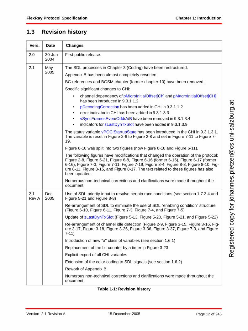
Vers. Date Changes
2.0 30-Jun-2004
First public release.
2.1 May 2005
The SDL processes in Chapter 3 (Coding) have been restructured.
Appendix B has been almost completely rewritten.
BG references and BGSM chapter (former chapter 10) have been removed.
Specific significant changes to CHI:
• channel dependency of pMicroInitialOffset[Ch] and pMacroInitialOffset[CH] has been introduced in 9.3.1.1.2
• pDecodingCorrection has been added in CHI in 9.3.1.1.2 • error indicator in CHI has been added in 9.3.1.3.3• vSyncFramesEven/Odd/A/B have been removed in 9.3.1.3.4• indicators for zLastDynTxSlot have been added in 9.3.1.3.9
The status variable vPOC!StartupState has been introduced in the CHI in 9.3.1.3.1. The variable is reset in Figure 2-6 to Figure 2-8 and set in Figure 7-11 to Figure 7-19.
Figure 6-10 was split into two figures (now Figure 6-10 and Figure 6-11).
The following figures have modifications that changed the operation of the protocol: Figure 2-8, Figure 5-21, Figure 6-8, Figure 6-16 (former 6-15), Figure 6-17 (former 6-16), Figure 7-3, Figure 7-11, Figure 7-19, Figure 8-4, Figure 8-8, Figure 8-10, Fig-ure 8-11, Figure 8-15, and Figure 8-17. The text related to these figures has also been updated.
Numerous non-technical corrections and clarifications were made throughout the document.
2.1Rev A
Dec2005
Use of SDL priority input to resolve certain race conditions (see section 1.7.3.4 and Figure 5-21 and Figure 8-8)
Re-arrangement of SDL to eliminate the use of SDL "enabling condition" structure (Figure 6-10, Figure 6-11, Figure 7-3, Figure 7-4, and Figure 7-5)
Update of zLastDynTxSlot (Figure 5-13, Figure 5-20, Figure 5-21, and Figure 5-22)
Re-arrangement of channel idle detection (Figure 2-9, Figure 3-15, Figure 3-16, Fig-ure 3-17, Figure 3-18, Figure 3-25, Figure 3-36, Figure 3-37, Figure 7-3, and Figure 7-11)
Introduction of new "a" class of variables (see section 1.6.1)
Replacement of the bit counter by a timer in Figure 3-23
Explicit export of all CHI variables
Extension of the color coding to SDL signals (see section 1.6.2)
Rework of Appendix B
Numerous non-technical corrections and clarifications were made throughout the document.
Table 1-1: Revision history
Version 2.1 Revision A 15-December-2005 Page 12 of 245
FlexRay Protocol Specification Chapter 1: Introduction
Reg
iste
red
copy
for
joha
nnes
.ple
tzer
@cs
.uni
-sal
zbur
g.at
1.4 Terms and definitions
application data
data produced and/or used by application tasks. In the automotive context the term 'signal' is often used for application data exchanged among tasks.
bus
a communication system topology in which nodes are directly connected to a single, common communication media (as opposed to connection through stars, gateways, etc.). The term bus is also used to refer to the media itself.
bus driver
an electronic component consisting of a transmitter and a receiver that connects a communication controller to one communication channel.
bus guardian
an electronic component that protects a channel from interference caused by communication that is not temporally aligned with the cluster's communication schedule by limiting the times that a communication controller can transmit to those times allowed by the schedule.
channel
see communication channel.
channel idle
the condition of medium idle as perceived by each individual node in the network.
clique
set of communication controllers having the same view of certain systems properties, e.g., the global time value or the activity state of communication controllers.
cluster
a communication system of multiple nodes connected via at least one communication channel directly (bus topology) or by star couplers (star topology).
coldstart node
a node capable of initiating the communication startup procedure on the cluster by sending startup frames.
communication channel
the inter-node connection through which signals are conveyed for the purpose of communication. The communication channel abstracts both the network topology, i.e., bus or star, as well as the physical transmission medium, i.e. electrical or optical.
communication controller (CC)
an electronic component in a node that is responsible for implementing the protocol aspects of the FlexRay communications system.
Version 2.1 Revision A 15-December-2005 Page 13 of 245
FlexRay Protocol Specification Chapter 1: Introduction
Reg
iste
red
copy
for
joha
nnes
.ple
tzer
@cs
.uni
-sal
zbur
g.at
communication cycle
one complete instance of the communication structure that is periodically repeated to comprise the media access method of the FlexRay system. The communication cycle consists of a static segment, an optional dynamic segment, an optional symbol window, and a network idle time.
communication slot
an interval of time during which access to a communication channel is granted exclusively to a specific node for the transmission of a frame with a frame ID corresponding to the slot. FlexRay distinguishes between static communication slots and dynamic communication slots.
cycle counter
the number of the current communication cycle.
cycle time
the time within the current communication cycle, expressed in units of macroticks. Cycle time is reset to zero at the beginning of each communication cycle.
dynamic segment
portion of the communication cycle where the media access is controlled via a mini-slotting scheme, also known as Flexible Time Division Multiple Access (FTDMA). During this segment access to the media is dynamically granted on a priority basis to nodes with data to transmit.
dynamic communication slot
an interval of time within the dynamic segment of the communication cycle consisting of one or more minislots during which access to a communication channel is granted exclusively to a specific node for transmission of a frame with a frame ID corresponding to the slot. In contrast to a static communication slot, the duration of a dynamic communication slot may vary depending on the length of the frame. If no frame is sent, the duration of a dynamic communication slot equals that of one minislot.
frame
a structure used by the communication system to exchange information within the system. A frame consists of a header segment, a payload segment and a trailer segment. The payload segment is used to convey application data.
frame identifier
the frame identifier defines the slot position in the static segment and defines the priority in the dynamic segment. A lower identifier indicates a higher priority.
gateway
a node that is connected to two or more independent communication networks that allows information to flow between the networks.
global time
combination of cycle counter and cycle time.
Hamming distance
the minimum distance (i.e., the number of bits which differ) between any two valid code words in a binary code.
Version 2.1 Revision A 15-December-2005 Page 14 of 245
FlexRay Protocol Specification Chapter 1: Introduction
Reg
iste
red
copy
for
joha
nnes
.ple
tzer
@cs
.uni
-sal
zbur
g.at
host
the part of an ECU where the application software is executed, separated by the CHI from the FlexRay protocol engine.
macrotick
an interval of time derived from the cluster-wide clock synchronization algorithm. A macrotick consists of an integral number of microticks. The actual number of microticks in a given macrotick is adjusted by the clock synchronization algorithm. The macrotick represents the smallest granularity unit of the global time.
medium idle
the condition of the physical transmission medium when no node is actively transmitting on the physical transmission medium.
microtick
an interval of time derived directly from the CC's oscillator (possibly through the use of a prescaler). The microtick is not affected by the clock synchronization mechanisms, and is thus a node-local concept. Different nodes can have microticks of different duration.
minislot
an interval of time within the dynamic segment of the communication cycle that is of constant duration (in terms of macroticks) and that is used by the synchronized FTDMA media access scheme to manage media arbitration.
network
the combination of the communication channels that connect the nodes of a cluster.
network topology
the arrangement of the connections between the nodes. FlexRay supports bus, star, cascaded star, and hybrid network topologies.
node
a logical entity connected to the network that is capable of sending and/or receiving frames.
null frame
a frame that contains no usable data in the payload segment. A null frame is indicated by a bit in the header segment, and all data bytes in the payload segment are set to zero.
physical communication link
an inter-node connection through which signals are conveyed for the purpose of communication. All nodes connected to a given physical communication link share the same electrical or optical signals (i.e., they are not connected through repeaters, stars, gateways, etc.). Examples of a physical communication link include a bus network or a point-to-point connection between a node and a star. A communication channel may be constructed by combining one or more physical communication links together using stars.
precision
the worst-case deviation between the corresponding macroticks of any two synchronized nodes in the cluster.
Version 2.1 Revision A 15-December-2005 Page 15 of 245
FlexRay Protocol Specification Chapter 1: Introduction
Reg
iste
red
copy
for
joha
nnes
.ple
tzer
@cs
.uni
-sal
zbur
g.at
slot
see communication slot.
star
a device that allows information to be transferred from one physical communication link to one or more other physical communication links. A star duplicates information present on one of its links to the other links connected to the star. A star can be either passive or active.
startup frame
FlexRay frame whose header segment contains an indicator that integrating nodes may use time-related information from this frame for initialization during the startup process. Startup frames are always also sync frames.
startup slot
communication slot in which a startup frame is sent.
static communication slot
an interval of time within the static segment of the communication cycle that is constant in terms of macroticks and during which access to a communication channel is granted exclusively to a specific node for transmission of a frame with a frame ID corresponding to the slot. Unlike a dynamic communication slot, each static communication slot contains a constant number of macroticks regardless of whether or not a frame is sent in the slot.
static segment
portion of the communication cycle where the media access is controlled via a static Time Division Multiple Access (TDMA) scheme. During this segment access to the media is determined solely by the progression of time.
sync frame
FlexRay frame whose header segment contains an indicator that the deviation measured between the frame's arrival time and its expected arrival time should be used by the clock synchronization algorithm.
sync slot
communication slot in which a sync frame is sent.
1.5 Acronyms and abbreviations
µT Microtick
AP Action Point
BD Bus Driver
BIST Built-In Self Test
BITSTRB Bit Strobing Process
BSS Byte Start Sequence
CAS Collision Avoidance Symbol
CC Communication Controller
Version 2.1 Revision A 15-December-2005 Page 16 of 245
FlexRay Protocol Specification Chapter 1: Introduction
Reg
iste
red
copy
for
joha
nnes
.ple
tzer
@cs
.uni
-sal
zbur
g.at
CE Communication Element
CHI Controller Host Interface
CHIRP Channel Idle Recognition Point
CODEC Coding and Decoding Process
CRC Cyclic Redundancy Code
CSP Clock Synchronization Process
CSS Clock Synchronization Startup Process
DTS Dynamic Trailing Sequence
ECU Electronic Control Unit, same as node
EMC Electromagnetic Compatibility
ERRN Error Not signal
FES Frame End Sequence
FSP Frame and Symbol Processing
FSS Frame Start Sequence
FTDMA Flexible Time Division Multiple Access (media access method)
FTM Fault Tolerant Midpoint
ID Identifier
INH Inhibit signal
MAC Media Access Control Process
MT Macrotick
MTG Macrotick Generation Process
MTS Media Access Test Symbol
NIT Network Idle Time
NM Network Management
POC Protocol Operation Control
RxD Receive data signal from bus driver
RxEN Receive data enable signal from bus driver
SDL Specification and Description Language
SPI Serial Peripheral Interface
STBN Standby Not signal
SuF Startup Frame
SW Symbol Window
SyF Sync Frame
TDMA Time Division Multiple Access (media access method)
TRP Time Reference Point
TSS Transmission Start Sequence
Version 2.1 Revision A 15-December-2005 Page 17 of 245

FlexRay Protocol Specification Chapter 1: Introduction
Reg
iste
red
copy
for
joha
nnes
.ple
tzer
@cs
.uni
-sal
zbur
g.at
TxD Transmit Data signal from CC
TxEN Transmit Data Enable Not signal from CC
WUP Wakeup Pattern
WUS Wakeup Symbol
WUPDEC Wakeup Pattern Decoding Process
1.6 Notational conventions
1.6.1 Parameter prefix conventions<variable> ::= <prefix_1> [<prefix_2>] Name
<prefix_1>::= a | c | v | g | p | z
<prefix_2>::= d | s
1.6.2 Color codingThroughout the text several types of items are highlighted through the use of an italicized color font.
Naming Convention
Information Type
Description
a Auxiliary Parameter
Auxiliary parameter used in the definition or derivation of other parameters or in the derivation of constraints.
c Protocol Constant
Values used to define characteristics or limits of the protocol. These values are fixed for the protocol and cannot be changed.
v Node Variable Values that vary depending on time, events, etc.
g Cluster Parameter
Parameter that must have the same value in all nodes in a cluster, is initialized in the POC:default config state, and can only be changed while in the POC:config state.
p Node Para-meter
Parameter that may have different values in different nodes in the cluster, is initialized in the POC:default config state, and can only be changed while in the POC:config state.
z Local SDL Process Variable
Variables used in SDL processes to facilitate accurate representa-tion of the necessary algorithmic behavior. Their scope is local to the process where they are declared and their existence in any particu-lar implementation is not mandated by the protocol.
Table 1-2: Parameter prefix 1.
Naming Convention
Information Type
Description
d Time Duration Value (variable, parameter, etc.) describing a time duration, the time between two points in time
s Set Set of values (variables, parameters, etc.)
Table 1-3: Parameter prefix 2.
Version 2.1 Revision A 15-December-2005 Page 18 of 245
FlexRay Protocol Specification Chapter 1: Introduction
Reg
iste
red
copy
for
joha
nnes
.ple
tzer
@cs
.uni
-sal
zbur
g.at
Parameters, constants and variables are highlighted with blue italics. An example is the parameter gdStat-icSlot. This convention is not used within SDL diagrams, as it is assumed that such information is obvious.The meaning of the prefixes of parameters, constants, and variables is described in section 1.6.1.
SDL states are highlighted in green italics. An example is the SDL state POC:normal active. Thishighlighting convention is not used within SDL diagrams. Further notational conventions related to SDLstates are described in section 1.7.2.
SDL signals are highlighted in brown italics. An example is the SDL signal CHIRP on A. Again, thisconvention is not used within the SDL diagrams themselves as the fact that an item is an input or outputsignal should be obvious.
Terms which are important for FlexRay are highlighted in red italics at their first (or defining) instance in thetext. An example is the term communication element.
1.7 SDL conventions
1.7.1 GeneralThe FlexRay protocol mechanisms described in this specification are presented using a graphical methodloosely based on the Specification and Description Language (SDL) technique described in [Z100]. Theintent of this description is not to provide a complete executable SDL model of the protocol mechanisms,but rather to present a reasonably unambiguous description of the mechanisms and their interactions. Thisdescription is intended to be read by humans, not by machines, and in many cases the description isoptimized for understandability rather than exact syntactic correctness.
The SDL descriptions in this specification are behavioral descriptions, not requirements on a particularmethod of implementation. In many cases the method of description was chosen for ease of understandingrather than efficiency of implementation. An actual implementation should have the same behavior as theSDL description, but it need not have the same underlying structure or mechanisms.
Several SDL diagrams have textual descriptions intended to assist the reader in understanding the behaviordepicted in the SDL diagrams. Some technical details are intentionally omitted from these explanations.Unless specifically mentioned, the behavior depicted in the SDL diagrams takes precedence over anytextual description.
The SDL in this specification describes a dual channel FlexRay device. As a result, there are a number ofmechanisms that exhibit behavior that is specific to a given channel. It is also possible to have FlexRaydevices that only support a single channel, or that may be configured to support a single channel. Imple-menters of single channel devices will have to make appropriate adjustments to eliminate the effects ofmechanisms and signals that do not exist in devices operating in a single channel mode.
1.7.2 SDL Notational ConventionsStates that exist within the various SDL processes are shown with the state symbol shaded in light gray.These states are named with all lowercase letters. Acronyms or proper nouns that appear in a state nameare capitalized as appropriate. Examples include the states "wait for sync frame" and "wait for CE start".
SDL states that are referenced in the text are prefixed with an identification of the SDL process in whichthey are located (for example, the state POC:normal active refers to the "normal active" state in the POCprocess). This convention is not used within the SDL diagrams themselves, as the process informationshould be obvious.
The definitions of an SDL process are often spread over several different figures. The caption of each figurethat contains SDL definitions indicates to which SDL process the figure belongs.
Version 2.1 Revision A 15-December-2005 Page 19 of 245
FlexRay Protocol Specification Chapter 1: Introduction
Reg
iste
red
copy
for
joha
nnes
.ple
tzer
@cs
.uni
-sal
zbur
g.at
1.7.3 SDL ExtensionsThe SDL descriptions in this specification contain some constructs that are not a part of normal SDL. Also,some mechanisms described with constructs that are part of normal SDL expect that these constructsbehave somewhat differently than is described in [Z100]. This section documents significant deviations from"standard" SDL.
1.7.3.1 Microtick, macrotick and sample tick timers
The representation of time in the FlexRay protocol is based on a hierarchy that includes microticks andmacroticks (see Chapter 8 for details). Several SDL mechanisms need timers that measure a certainnumber of microticks or macroticks. This specification makes use of an extension of the SDL 'timer'construct to accomplish this.
An SDL definition of the form
µT timer
defines a timer that counts in terms of microticks. This behavior would be similar to that of an SDL systemwhose underlying time unit is the microtick.
An SDL definition of the form
MT timer
defines a timer that counts in terms of macroticks. Note that a macrotick timer uses the corrected macroticksgenerated by the macrotick generation process. Since the duration of a macrotick can vary, the duration ofthese timers can also vary, but the timers themselves remain synchronized to the macrotick-level timebaseof the protocol.
In all other respects both of these constructs behave in the same manner as normal SDL timers.
In addition to the above, several SDL mechanisms used in the description of encoding make use of a timerthat measures a certain number of ticks of the bit sample clock. An SDL definition of the form
ST timer
defines a timer that counts in terms of ticks of the bit sample clock (i.e., sample ticks). This behavior wouldbe similar to that of an SDL system whose underlying time unit is the sample tick. In all other respects thisconstruct behaves in the same manner as a normal SDL timer.
There is a defined relationship between the "ticks" of the microtick timebase and the sample ticks of bitsampling. Specifically, a microtick consists of an integral number, pSamplesPerMicrotick, of sample ticks.As a result, there is a fixed phase relationship between the microtick timebase and the ticks of the sampleclock.
The time expression of a timer is defined in [Z100] by:
<Time expression> = now + <Duration constant expression>
In this specification the time expression is used in the following simplified way:
<Time expression> = <Duration constant expression>3
1.7.3.2 Microtick behavior of the 'now' - expression
The behavioral descriptions of various aspects of the FlexRay system require the ability to take "time-stamps" at the occurrence of certain events. The granularity of these timestamps is one microtick, and thetimestamps taken by different processes need to be taken against the same underlying timebase. Thisspecification makes use of an extension of the SDL concept of time to facilitate these timestamps.
3 If the duration time expression is zero or negative then the timer is started and expires immediately.
Version 2.1 Revision A 15-December-2005 Page 20 of 245
FlexRay Protocol Specification Chapter 1: Introduction
Reg
iste
red
copy
for
joha
nnes
.ple
tzer
@cs
.uni
-sal
zbur
g.at
This specification assumes the existence of an underlying microtick timebase. This timebase, which isavailable to all processes, contains a microtick counter that is started at zero at some arbitrary epochassumed to occur before system startup. As time progresses, this timebase increments the microtickcounter without bound4. Explicit use of the SDL 'now' construct returns the value of this microtick counter.The difference between the timestamps of two events represents the number of microticks that haveoccurred between the events.
1.7.3.3 Channel-specific process replication
The FlexRay protocol described in this specification is a dual channel protocol. Several of the mechanismsin the protocol are replicated on a channel basis, i.e., essentially identical mechanisms are executed, onefor channel A and one for channel B. This specification only provides SDL descriptions for the channel-specific processes on channel A - it is assumed that whenever a channel-specific process is defined forchannel A there is another, essentially identical, process defined for channel B, even though this process isnot explicitly described in the specification.
Channel-specific processes have names that include the identity of their channel (for example, "Clocksynchronization startup process on channel A [CSS_A]"). In addition, signals that leave a channel-specificprocess have signal names that include the identity of their channel (for example, the signal integrationaborted on A).
1.7.3.4 Handling of Priority Input Symbols
The SDL language contains certain ambiguities regarding the order of execution of processes if multipleprocesses have input queues that are not empty. For example, the usage of timers and clock oscillatorinputs causes multiple processes to be eligible for execution at the beginning of clock edges. Generally, thisposes no problem for the FlexRay specification, but for certain special cases it is not possible to specify therequired behavior in an unambiguous way without additional language constructs.
To resolve these situations the SDL priority input symbol is used, but with a slightly extended meaning.Whenever an input priority symbol is used, no other exit path of this state may be taken unless it isimpossible that the priority input could be triggered on the current microtick clock edge. Effectively, theexecution of the process in question is stalled until all other process have executed. Should multipleprocesses be in a state where they are sensitive to a priority input, all are executed last and in random order.The message queue is handled in the standard way, i.e. the signal triggering the priority input is removedfrom the queue while any signals placed before or after are preserved for the succeeding state.
1.8 Network topology considerations
The following sections provide a brief overview of the possible topologies for a FlexRay system. Thismaterial is for reference only - detailed requirements and specifications may be found in [EPL05].
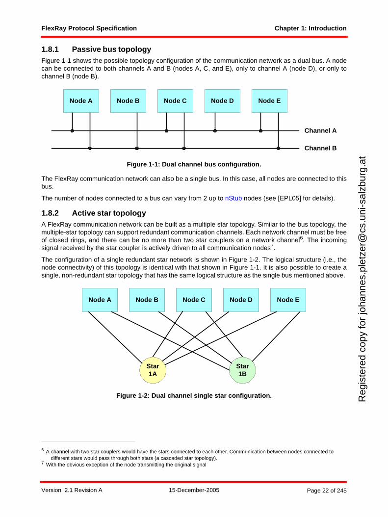
There are several ways to design a FlexRay cluster. It can be configured as a single-channel or dual-channel bus network, a single-channel or dual-channel star network, or in various hybrid combinations ofbus and star topologies.
A FlexRay cluster consists of at most two channels, identified as Channel A and Channel B. Each node inthe cluster may be connected to either or both of the channels. In the fault free condition, all nodesconnected to Channel A are able to communicate with all other nodes connected to Channel A, and allnodes connected to Channel B are able to communicate with all other nodes connected to Channel B. If anode needs to be connected to more than one cluster then the connection to each cluster must be madethrough a different communication controller5.
4 This is in contrast to the vMicrotick variable, which is reset to zero at the beginning of each cycle.5 For example, it is not allowed for a communication controller to connect to Channel A of one cluster and Channel B of another
cluster.
Version 2.1 Revision A 15-December-2005 Page 21 of 245
FlexRay Protocol Specification Chapter 1: Introduction
Reg
iste
red
copy
for
joha
nnes
.ple
tzer
@cs
.uni
-sal
zbur
g.at
1.8.1 Passive bus topologyFigure 1-1 shows the possible topology configuration of the communication network as a dual bus. A nodecan be connected to both channels A and B (nodes A, C, and E), only to channel A (node D), or only tochannel B (node B).
Figure 1-1: Dual channel bus configuration.
The FlexRay communication network can also be a single bus. In this case, all nodes are connected to thisbus.
The number of nodes connected to a bus can vary from 2 up to nStub nodes (see [EPL05] for details).
1.8.2 Active star topologyA FlexRay communication network can be built as a multiple star topology. Similar to the bus topology, themultiple-star topology can support redundant communication channels. Each network channel must be freeof closed rings, and there can be no more than two star couplers on a network channel6. The incomingsignal received by the star coupler is actively driven to all communication nodes7.
The configuration of a single redundant star network is shown in Figure 1-2. The logical structure (i.e., thenode connectivity) of this topology is identical with that shown in Figure 1-1. It is also possible to create asingle, non-redundant star topology that has the same logical structure as the single bus mentioned above.
Figure 1-2: Dual channel single star configuration.
6 A channel with two star couplers would have the stars connected to each other. Communication between nodes connected to different stars would pass through both stars (a cascaded star topology).
7 With the obvious exception of the node transmitting the original signal
Channel A
Channel B
Node A Node B Node C Node D Node E
Node A Node B Node C Node D Node E
Star1A
Star1B
Version 2.1 Revision A 15-December-2005 Page 22 of 245
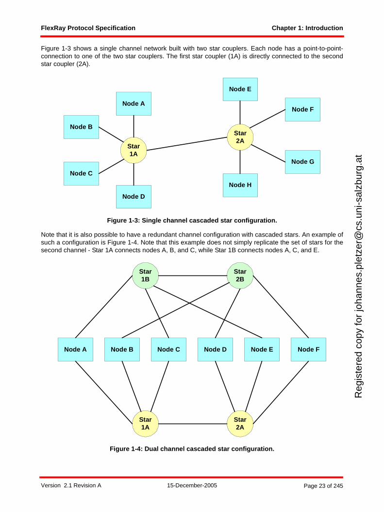
FlexRay Protocol Specification Chapter 1: Introduction
Reg
iste
red
copy
for
joha
nnes
.ple
tzer
@cs
.uni
-sal
zbur
g.at
Figure 1-3 shows a single channel network built with two star couplers. Each node has a point-to-point-connection to one of the two star couplers. The first star coupler (1A) is directly connected to the secondstar coupler (2A).
Figure 1-3: Single channel cascaded star configuration.
Note that it is also possible to have a redundant channel configuration with cascaded stars. An example ofsuch a configuration is Figure 1-4. Note that this example does not simply replicate the set of stars for thesecond channel - Star 1A connects nodes A, B, and C, while Star 1B connects nodes A, C, and E.
Figure 1-4: Dual channel cascaded star configuration.
Star1A
Star2A
Node C
Node E
Node F
Node H
Node G
Node A
Node B
Node D
Node A Node B Node C Node D Node E Node F
Star1A
Star1B
Star2A
Star2B
Version 2.1 Revision A 15-December-2005 Page 23 of 245
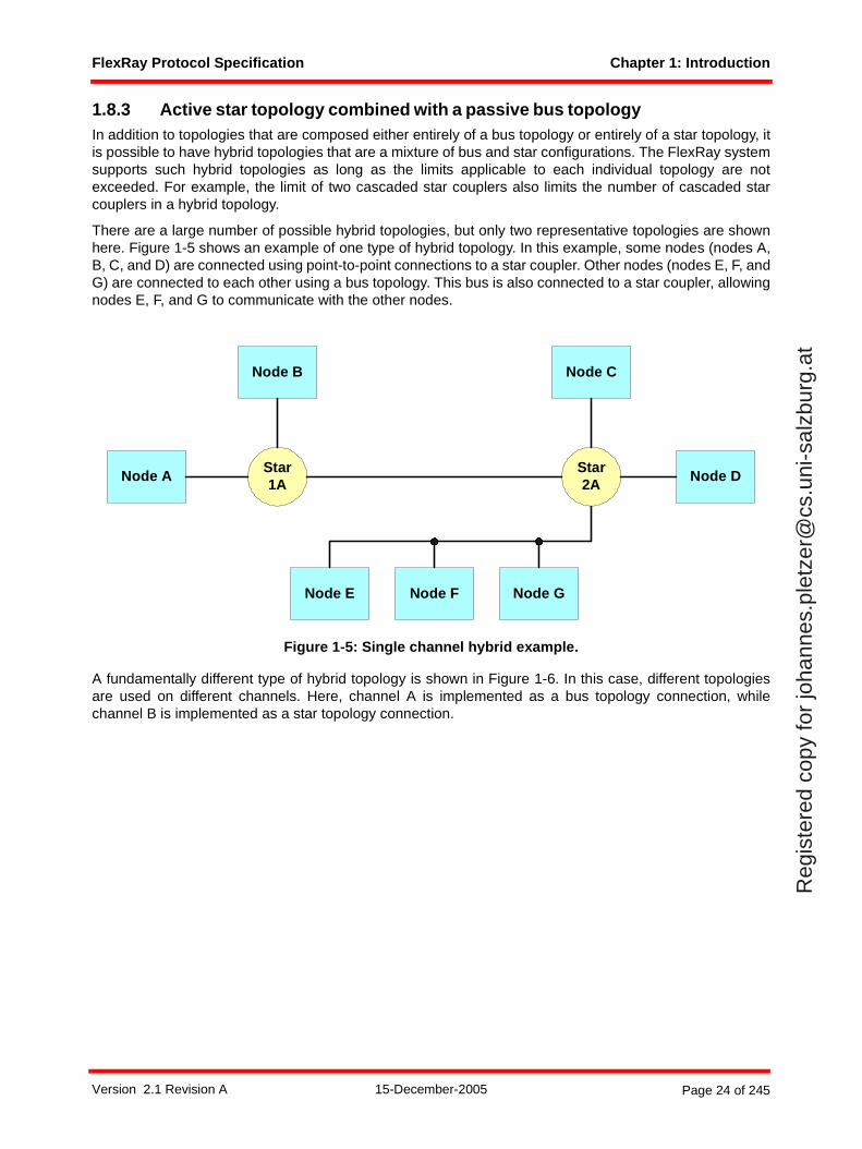
FlexRay Protocol Specification Chapter 1: Introduction
Reg
iste
red
copy
for
joha
nnes
.ple
tzer
@cs
.uni
-sal
zbur
g.at
1.8.3 Active star topology combined with a passive bus topologyIn addition to topologies that are composed either entirely of a bus topology or entirely of a star topology, itis possible to have hybrid topologies that are a mixture of bus and star configurations. The FlexRay systemsupports such hybrid topologies as long as the limits applicable to each individual topology are notexceeded. For example, the limit of two cascaded star couplers also limits the number of cascaded starcouplers in a hybrid topology.
There are a large number of possible hybrid topologies, but only two representative topologies are shownhere. Figure 1-5 shows an example of one type of hybrid topology. In this example, some nodes (nodes A,B, C, and D) are connected using point-to-point connections to a star coupler. Other nodes (nodes E, F, andG) are connected to each other using a bus topology. This bus is also connected to a star coupler, allowingnodes E, F, and G to communicate with the other nodes.
Figure 1-5: Single channel hybrid example.
A fundamentally different type of hybrid topology is shown in Figure 1-6. In this case, different topologiesare used on different channels. Here, channel A is implemented as a bus topology connection, whilechannel B is implemented as a star topology connection.
Star1A
Star2A
Node B Node C
Node DNode A
Node GNode FNode E
Version 2.1 Revision A 15-December-2005 Page 24 of 245
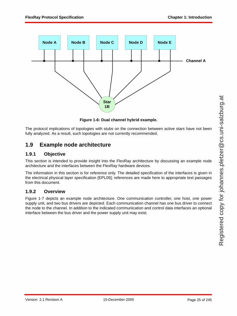
FlexRay Protocol Specification Chapter 1: Introduction
Reg
iste
red
copy
for
joha
nnes
.ple
tzer
@cs
.uni
-sal
zbur
g.at
Figure 1-6: Dual channel hybrid example.
The protocol implications of topologies with stubs on the connection between active stars have not beenfully analyzed. As a result, such topologies are not currently recommended.
1.9 Example node architecture
1.9.1 ObjectiveThis section is intended to provide insight into the FlexRay architecture by discussing an example nodearchitecture and the interfaces between the FlexRay hardware devices.
The information in this section is for reference only. The detailed specification of the interfaces is given inthe electrical physical layer specification [EPL05]; references are made here to appropriate text passagesfrom this document.
1.9.2 OverviewFigure 1-7 depicts an example node architecture. One communication controller, one host, one powersupply unit, and two bus drivers are depicted. Each communication channel has one bus driver to connectthe node to the channel. In addition to the indicated communication and control data interfaces an optionalinterface between the bus driver and the power supply unit may exist.
Node A Node B Node C Node D Node E
Star1B
Channel A
Version 2.1 Revision A 15-December-2005 Page 25 of 245
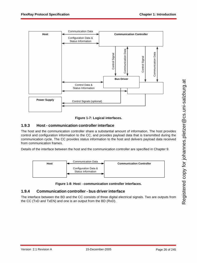
FlexRay Protocol Specification Chapter 1: Introduction
Reg
iste
red
copy
for
joha
nnes
.ple
tzer
@cs
.uni
-sal
zbur
g.at
Figure 1-7: Logical interfaces.
1.9.3 Host - communication controller interface The host and the communication controller share a substantial amount of information. The host providescontrol and configuration information to the CC, and provides payload data that is transmitted during thecommunication cycle. The CC provides status information to the host and delivers payload data receivedfrom communication frames.
Details of the interface between the host and the communication controller are specified in Chapter 9.
Figure 1-8: Host - communication controller interfaces.
1.9.4 Communication controller - bus driver interfaceThe interface between the BD and the CC consists of three digital electrical signals. Two are outputs fromthe CC (TxD and TxEN) and one is an output from the BD (RxD).
Host
Bus Driver
Communication Controller
Power Supply
Com
mun
icat
ion
Dat
a
Control Data &Status Information
Control Signals (optional)
Communication Data
Con
trol
Sig
nal
Com
mun
icat
ion
Dat
a
Con
trol
Sig
nal
Configuration Data &Status Information
Host Communication Controller
Configuration Data &Status Information
Communication Data
Version 2.1 Revision A 15-December-2005 Page 26 of 245
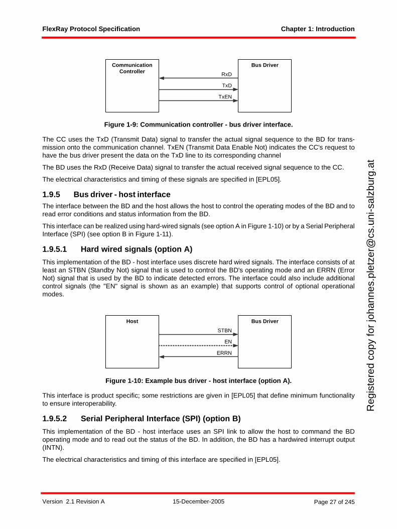
FlexRay Protocol Specification Chapter 1: Introduction
Reg
iste
red
copy
for
joha
nnes
.ple
tzer
@cs
.uni
-sal
zbur
g.at
Figure 1-9: Communication controller - bus driver interface.
The CC uses the TxD (Transmit Data) signal to transfer the actual signal sequence to the BD for trans-mission onto the communication channel. TxEN (Transmit Data Enable Not) indicates the CC's request tohave the bus driver present the data on the TxD line to its corresponding channel
The BD uses the RxD (Receive Data) signal to transfer the actual received signal sequence to the CC.
The electrical characteristics and timing of these signals are specified in [EPL05].
1.9.5 Bus driver - host interfaceThe interface between the BD and the host allows the host to control the operating modes of the BD and toread error conditions and status information from the BD.
This interface can be realized using hard-wired signals (see option A in Figure 1-10) or by a Serial PeripheralInterface (SPI) (see option B in Figure 1-11).
1.9.5.1 Hard wired signals (option A)
This implementation of the BD - host interface uses discrete hard wired signals. The interface consists of atleast an STBN (Standby Not) signal that is used to control the BD's operating mode and an ERRN (ErrorNot) signal that is used by the BD to indicate detected errors. The interface could also include additionalcontrol signals (the "EN" signal is shown as an example) that supports control of optional operationalmodes.
Figure 1-10: Example bus driver - host interface (option A).
This interface is product specific; some restrictions are given in [EPL05] that define minimum functionalityto ensure interoperability.
1.9.5.2 Serial Peripheral Interface (SPI) (option B)
This implementation of the BD - host interface uses an SPI link to allow the host to command the BDoperating mode and to read out the status of the BD. In addition, the BD has a hardwired interrupt output(INTN).
The electrical characteristics and timing of this interface are specified in [EPL05].
RxD
CommunicationController
TxD
TxEN
Bus Driver
STBN
EN
ERRN
Host Bus Driver
Version 2.1 Revision A 15-December-2005 Page 27 of 245
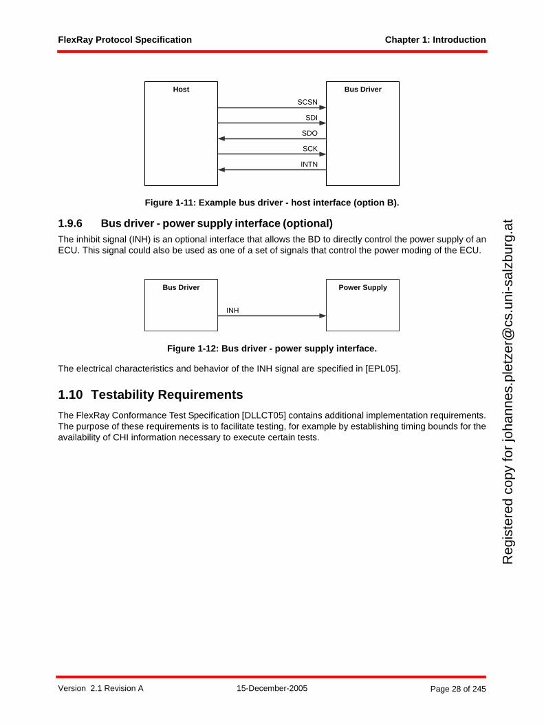
FlexRay Protocol Specification Chapter 1: Introduction
Reg
iste
red
copy
for
joha
nnes
.ple
tzer
@cs
.uni
-sal
zbur
g.at
Figure 1-11: Example bus driver - host interface (option B).
1.9.6 Bus driver - power supply interface (optional)The inhibit signal (INH) is an optional interface that allows the BD to directly control the power supply of anECU. This signal could also be used as one of a set of signals that control the power moding of the ECU.
Figure 1-12: Bus driver - power supply interface.
The electrical characteristics and behavior of the INH signal are specified in [EPL05].
1.10 Testability Requirements
The FlexRay Conformance Test Specification [DLLCT05] contains additional implementation requirements.The purpose of these requirements is to facilitate testing, for example by establishing timing bounds for theavailability of CHI information necessary to execute certain tests.
INTN
SCK
SDO
SDI
Bus DriverHost
SCSN
INH
Power SupplyBus Driver
Version 2.1 Revision A 15-December-2005 Page 28 of 245
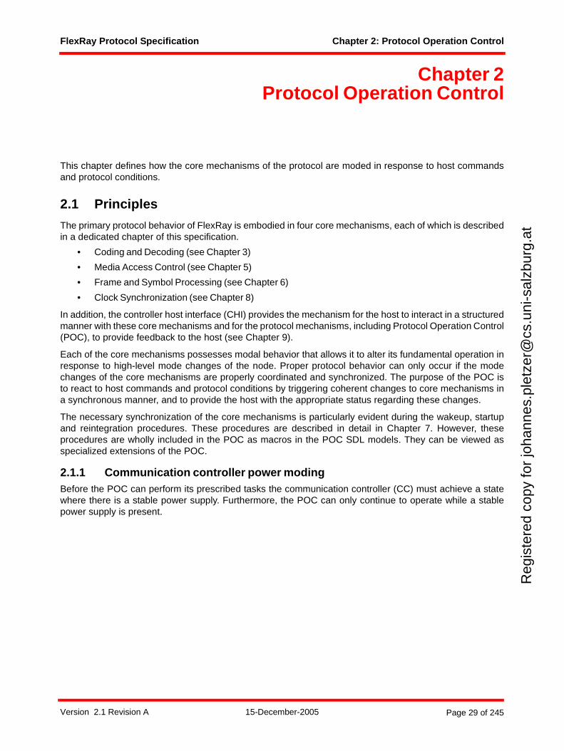
FlexRay Protocol Specification Chapter 2: Protocol Operation Control
Reg
iste
red
copy
for
joha
nnes
.ple
tzer
@cs
.uni
-sal
zbur
g.at
Chapter 2Protocol Operation Control
This chapter defines how the core mechanisms of the protocol are moded in response to host commandsand protocol conditions.
2.1 Principles
The primary protocol behavior of FlexRay is embodied in four core mechanisms, each of which is describedin a dedicated chapter of this specification.
• Coding and Decoding (see Chapter 3)
• Media Access Control (see Chapter 5)
• Frame and Symbol Processing (see Chapter 6)
• Clock Synchronization (see Chapter 8)
In addition, the controller host interface (CHI) provides the mechanism for the host to interact in a structuredmanner with these core mechanisms and for the protocol mechanisms, including Protocol Operation Control(POC), to provide feedback to the host (see Chapter 9).
Each of the core mechanisms possesses modal behavior that allows it to alter its fundamental operation inresponse to high-level mode changes of the node. Proper protocol behavior can only occur if the modechanges of the core mechanisms are properly coordinated and synchronized. The purpose of the POC isto react to host commands and protocol conditions by triggering coherent changes to core mechanisms ina synchronous manner, and to provide the host with the appropriate status regarding these changes.
The necessary synchronization of the core mechanisms is particularly evident during the wakeup, startupand reintegration procedures. These procedures are described in detail in Chapter 7. However, theseprocedures are wholly included in the POC as macros in the POC SDL models. They can be viewed asspecialized extensions of the POC.
2.1.1 Communication controller power modingBefore the POC can perform its prescribed tasks the communication controller (CC) must achieve a statewhere there is a stable power supply. Furthermore, the POC can only continue to operate while a stablepower supply is present.
Version 2.1 Revision A 15-December-2005 Page 29 of 245
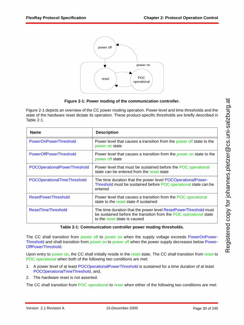
FlexRay Protocol Specification Chapter 2: Protocol Operation Control
Reg
iste
red
copy
for
joha
nnes
.ple
tzer
@cs
.uni
-sal
zbur
g.at
Figure 2-1: Power moding of the communication controller.
Figure 2-1 depicts an overview of the CC power moding operation. Power level and time thresholds and thestate of the hardware reset dictate its operation. These product-specific thresholds are briefly described inTable 2-1.
The CC shall transition from power off to power on when the supply voltage exceeds PowerOnPower-Threshold and shall transition from power on to power off when the power supply decreases below Power-OffPowerThreshold.
Upon entry to power on, the CC shall initially reside in the reset state. The CC shall transition from reset toPOC operational when both of the following two conditions are met:
1. A power level of at least POCOperationalPowerThreshold is sustained for a time duration of at least POCOperationalTimeThreshold, and,
2. The hardware reset is not asserted.
The CC shall transition from POC operational to reset when either of the following two conditions are met:
Name Description
PowerOnPowerThreshold Power level that causes a transition from the power off state to the power on state
PowerOffPowerThreshold Power level that causes a transition from the power on state to thepower off state
POCOperationalPowerThreshold Power level that must be sustained before the POC operational state can be entered from the reset state
POCOperationalTimeThreshold The time duration that the power level POCOperationalPower-Threshold must be sustained before POC operational state can be entered
ResetPowerThreshold Power level that causes a transition from the POC operational state to the reset state if sustained
ResetTimeThreshold The time duration that the power level ResetPowerThreshold must be sustained before the transition from the POC operational state to the reset state is caused
Table 2-1: Communication controller power moding thresholds.
power off
POCoperational
reset
power on
Version 2.1 Revision A 15-December-2005 Page 30 of 245

FlexRay Protocol Specification Chapter 2: Protocol Operation Control
Reg
iste
red
copy
for
joha
nnes
.ple
tzer
@cs
.uni
-sal
zbur
g.at
1. A power level of no more than ResetPowerThreshold but still greater than PowerOffPowerThreshold, is sustained for a time duration of at least ResetTimeThreshold, or,
2. The hardware reset is asserted.
In the power off state there is insufficient power for the CC to operate8. In the power on state (including bothreset and POC operational) the CC shall guarantee that all pins are in prescribed states. In the POC opera-tional state the CC shall drive the pins in accordance with the product specification. The POC controls theother protocol mechanisms in the manner described in this chapter while the CC is in the POC operationalstate.
2.2 Description
The relationships between the CHI, POC and the core mechanisms are depicted in Figure 2-29.
8 While the CC cannot enforce specific behavior of the pins, there shall be product-specific behavior specified (e.g. high impedance).
9 The dark lines represent data flows between mechanisms that are relevant to this chapter. The lighter gray lines are relevant to the protocol, but not to this chapter.
Version 2.1 Revision A 15-December-2005 Page 31 of 245
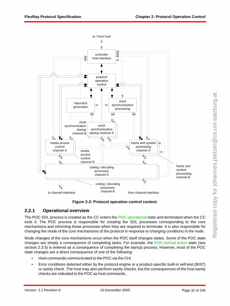
FlexRay Protocol Specification Chapter 2: Protocol Operation Control
Reg
iste
red
copy
for
joha
nnes
.ple
tzer
@cs
.uni
-sal
zbur
g.at
Figure 2-2: Protocol operation control context.
2.2.1 Operational overviewThe POC SDL process is created as the CC enters the POC operational state and terminated when the CCexits it. The POC process is responsible for creating the SDL processes corresponding to the coremechanisms and informing those processes when they are required to terminate. It is also responsible forchanging the mode of the core mechanisms of the protocol in response to changing conditions in the node.
Mode changes of the core mechanisms occur when the POC itself changes states. Some of the POC statechanges are simply a consequence of completing tasks. For example, the POC:normal active state (seesection 2.3.5) is entered as a consequence of completing the startup process. However, most of the POCstate changes are a direct consequence of one of the following:
• Host commands communicated to the POC via the CHI.
• Error conditions detected either by the protocol engine or a product-specific built-in self-test (BIST)or sanity check. The host may also perform sanity checks, but the consequences of the host sanitychecks are indicated to the POC as host commands.
frame and symbolprocessing
media accesscontrol
clocksynchronization
startup
macrotickgeneration
clocksynchronization
processing
protocoloperation
control
controllerhost interface
coding / decodingprocesseschannel A
frame and symbolprocessingchannel A
media accesscontrol
channel A
clocksynchronization
startup channel A
to channel interface from channel interface
to / from host
mediaaccesscontrolchannel B
coding / decodingprocesseschannel B
frame andsymbolprocessingchannel B
clocksynchronization
startupchannel B
Version 2.1 Revision A 15-December-2005 Page 32 of 245
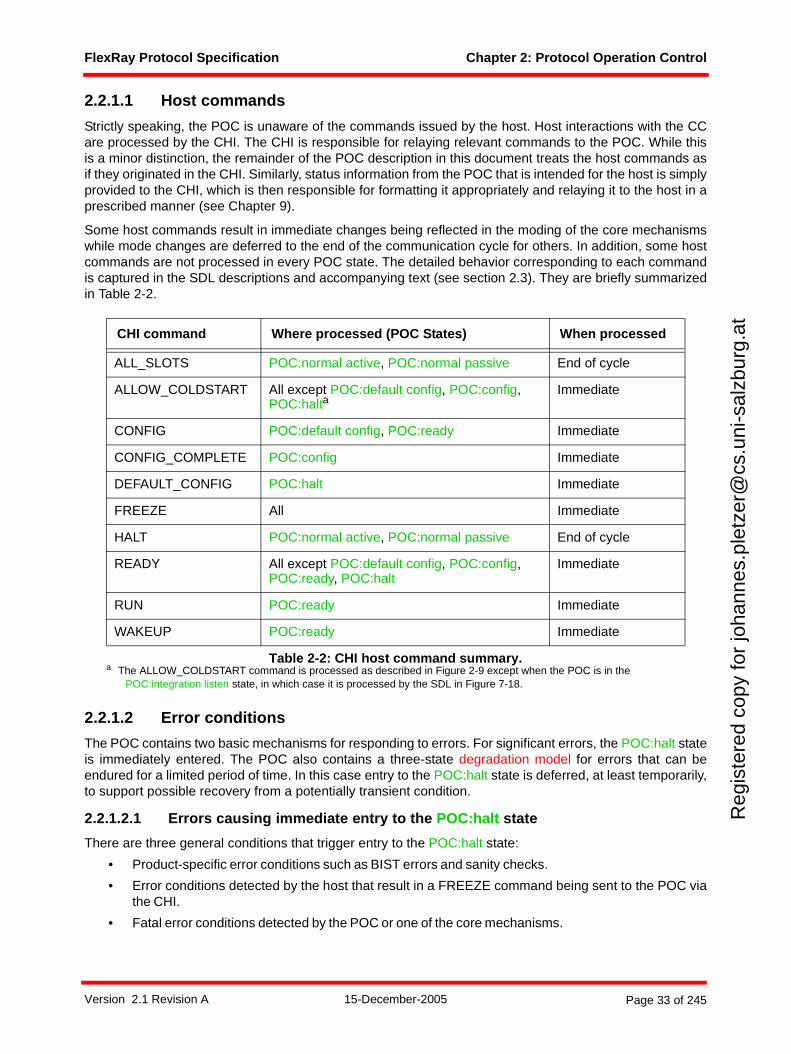
FlexRay Protocol Specification Chapter 2: Protocol Operation Control
Reg
iste
red
copy
for
joha
nnes
.ple
tzer
@cs
.uni
-sal
zbur
g.at
2.2.1.1 Host commands
Strictly speaking, the POC is unaware of the commands issued by the host. Host interactions with the CCare processed by the CHI. The CHI is responsible for relaying relevant commands to the POC. While thisis a minor distinction, the remainder of the POC description in this document treats the host commands asif they originated in the CHI. Similarly, status information from the POC that is intended for the host is simplyprovided to the CHI, which is then responsible for formatting it appropriately and relaying it to the host in aprescribed manner (see Chapter 9).
Some host commands result in immediate changes being reflected in the moding of the core mechanismswhile mode changes are deferred to the end of the communication cycle for others. In addition, some hostcommands are not processed in every POC state. The detailed behavior corresponding to each commandis captured in the SDL descriptions and accompanying text (see section 2.3). They are briefly summarizedin Table 2-2.
2.2.1.2 Error conditions
The POC contains two basic mechanisms for responding to errors. For significant errors, the POC:halt stateis immediately entered. The POC also contains a three-state degradation model for errors that can beendured for a limited period of time. In this case entry to the POC:halt state is deferred, at least temporarily,to support possible recovery from a potentially transient condition.
2.2.1.2.1 Errors causing immediate entry to the POC:halt state
There are three general conditions that trigger entry to the POC:halt state:
• Product-specific error conditions such as BIST errors and sanity checks.
• Error conditions detected by the host that result in a FREEZE command being sent to the POC viathe CHI.
• Fatal error conditions detected by the POC or one of the core mechanisms.
CHI command Where processed (POC States) When processed
ALL_SLOTS POC:normal active, POC:normal passive End of cycle
ALLOW_COLDSTART All except POC:default config, POC:config, POC:halta
a The ALLOW_COLDSTART command is processed as described in Figure 2-9 except when the POC is in the POC:integration listen state, in which case it is processed by the SDL in Figure 7-18.
Immediate
CONFIG POC:default config, POC:ready Immediate
CONFIG_COMPLETE POC:config Immediate
DEFAULT_CONFIG POC:halt Immediate
FREEZE All Immediate
HALT POC:normal active, POC:normal passive End of cycle
READY All except POC:default config, POC:config, POC:ready, POC:halt
Immediate
RUN POC:ready Immediate
WAKEUP POC:ready Immediate
Table 2-2: CHI host command summary.
Version 2.1 Revision A 15-December-2005 Page 33 of 245
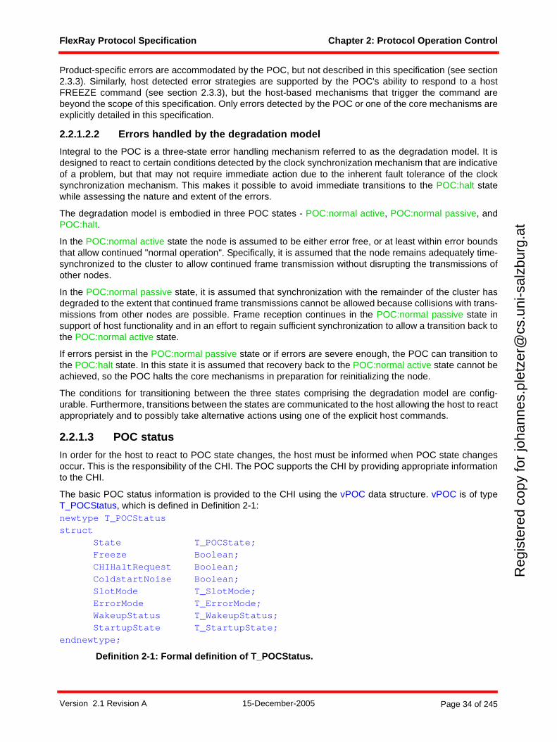
FlexRay Protocol Specification Chapter 2: Protocol Operation Control
Reg
iste
red
copy
for
joha
nnes
.ple
tzer
@cs
.uni
-sal
zbur
g.at
Product-specific errors are accommodated by the POC, but not described in this specification (see section2.3.3). Similarly, host detected error strategies are supported by the POC's ability to respond to a hostFREEZE command (see section 2.3.3), but the host-based mechanisms that trigger the command arebeyond the scope of this specification. Only errors detected by the POC or one of the core mechanisms areexplicitly detailed in this specification.
2.2.1.2.2 Errors handled by the degradation model
Integral to the POC is a three-state error handling mechanism referred to as the degradation model. It isdesigned to react to certain conditions detected by the clock synchronization mechanism that are indicativeof a problem, but that may not require immediate action due to the inherent fault tolerance of the clocksynchronization mechanism. This makes it possible to avoid immediate transitions to the POC:halt statewhile assessing the nature and extent of the errors.
The degradation model is embodied in three POC states - POC:normal active, POC:normal passive, andPOC:halt.
In the POC:normal active state the node is assumed to be either error free, or at least within error boundsthat allow continued "normal operation". Specifically, it is assumed that the node remains adequately time-synchronized to the cluster to allow continued frame transmission without disrupting the transmissions ofother nodes.
In the POC:normal passive state, it is assumed that synchronization with the remainder of the cluster hasdegraded to the extent that continued frame transmissions cannot be allowed because collisions with trans-missions from other nodes are possible. Frame reception continues in the POC:normal passive state insupport of host functionality and in an effort to regain sufficient synchronization to allow a transition back tothe POC:normal active state.
If errors persist in the POC:normal passive state or if errors are severe enough, the POC can transition tothe POC:halt state. In this state it is assumed that recovery back to the POC:normal active state cannot beachieved, so the POC halts the core mechanisms in preparation for reinitializing the node.
The conditions for transitioning between the three states comprising the degradation model are config-urable. Furthermore, transitions between the states are communicated to the host allowing the host to reactappropriately and to possibly take alternative actions using one of the explicit host commands.
2.2.1.3 POC status
In order for the host to react to POC state changes, the host must be informed when POC state changesoccur. This is the responsibility of the CHI. The POC supports the CHI by providing appropriate informationto the CHI.
The basic POC status information is provided to the CHI using the vPOC data structure. vPOC is of typeT_POCStatus, which is defined in Definition 2-1:newtype T_POCStatusstruct
State T_POCState;Freeze Boolean;CHIHaltRequest Boolean;ColdstartNoise Boolean;SlotMode T_SlotMode;ErrorMode T_ErrorMode;WakeupStatus T_WakeupStatus;StartupState T_StartupState;
endnewtype;
Definition 2-1: Formal definition of T_POCStatus.
Version 2.1 Revision A 15-December-2005 Page 34 of 245
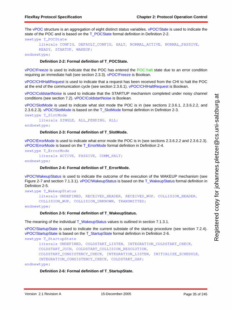
FlexRay Protocol Specification Chapter 2: Protocol Operation Control
Reg
iste
red
copy
for
joha
nnes
.ple
tzer
@cs
.uni
-sal
zbur
g.at
The vPOC structure is an aggregation of eight distinct status variables. vPOC!State is used to indicate thestate of the POC and is based on the T_POCState formal definition in Definition 2-2.newtype T_POCState
literals CONFIG, DEFAULT_CONFIG, HALT, NORMAL_ACTIVE, NORMAL_PASSIVE, READY, STARTUP, WAKEUP;endnewtype;
Definition 2-2: Formal definition of T_POCState.
vPOC!Freeze is used to indicate that the POC has entered the POC:halt state due to an error conditionrequiring an immediate halt (see section 2.3.3). vPOC!Freeze is Boolean.
vPOC!CHIHaltRequest is used to indicate that a request has been received from the CHI to halt the POCat the end of the communication cycle (see section 2.3.6.1). vPOC!CHIHaltRequest is Boolean.
vPOC!ColdstartNoise is used to indicate that the STARTUP mechanism completed under noisy channelconditions (see section 7.2). vPOC!ColdstartNoise is Boolean.
vPOC!SlotMode is used to indicate what slot mode the POC is in (see sections 2.3.6.1, 2.3.6.2.2, and2.3.6.2.3). vPOC!SlotMode is based on the T_SlotMode formal definition in Definition 2-3.newtype T_SlotMode
literals SINGLE, ALL_PENDING, ALL;endnewtype;
Definition 2-3: Formal definition of T_SlotMode.
vPOC!ErrorMode is used to indicate what error mode the POC is in (see sections 2.3.6.2.2 and 2.3.6.2.3).vPOC!ErrorMode is based on the T_ErrorMode formal definition in Definition 2-4.newtype T_ErrorMode
literals ACTIVE, PASSIVE, COMM_HALT;endnewtype;
Definition 2-4: Formal definition of T_ErrorMode.
vPOC!WakeupStatus is used to indicate the outcome of the execution of the WAKEUP mechanism (seeFigure 2-7 and section 7.1.3.1). vPOC!WakeupStatus is based on the T_WakeupStatus formal definition inDefinition 2-5.newtype T_WakeupStatus
literals UNDEFINED, RECEIVED_HEADER, RECEIVED_WUP, COLLISION_HEADER, COLLISION_WUP, COLLISION_UNKNOWN, TRANSMITTED;endnewtype;
Definition 2-5: Formal definition of T_WakeupStatus.
The meaning of the individual T_WakeupStatus values is outlined in section 7.1.3.1.
vPOC!StartupState is used to indicate the current substate of the startup procedure (see section 7.2.4).vPOC!StartupState is based on the T_StartupState formal definition in Definition 2-6.newtype T_StartupState
literals UNDEFINED, COLDSTART_LISTEN, INTEGRATION_COLDSTART_CHECK,COLDSTART_JOIN, COLDSTART_COLLISION_RESOLUTION,COLDSTART_CONSISTENCY_CHECK, INTEGRATION_LISTEN, INITIALIZE_SCHEDULE,INTEGRATION_CONSISTENCY_CHECK, COLDSTART_GAP;
endnewtype;
Definition 2-6: Formal definition of T_StartupState.
Version 2.1 Revision A 15-December-2005 Page 35 of 245
FlexRay Protocol Specification Chapter 2: Protocol Operation Control
Reg
iste
red
copy
for
joha
nnes
.ple
tzer
@cs
.uni
-sal
zbur
g.at
The individual T_StartupState values are the states within the STARTUP mechanism in section 7.2.4.
In addition to the vPOC data structure, the POC makes two counters available to the host via the CHI. Thesecounters are vClockCorrectionFailed and vAllowPassiveToActive, and are described in section 2.3.6.2.4.
2.2.1.4 SDL considerations for single channel nodes
FlexRay supports configurations where a node is only attached to one of the two possible FlexRay channels(see section 1.8). The POC behavior depicted in this chapter is that of a node connected to both channels.The behavior of a single channel variant is intuitively obvious. Specifically, the POC for this variant only
• Instantiates processes for the attached channel,
• Generates termination signals for the attached channel, and,
• Generates moding signals for the attached channel.
Process instantiation is depicted in Figure 2-5. The channel specific processes are readily identifiable bythe "_A" or "_B" text in the process names. The POC for a node attached to only one channel would onlyinstantiate the process set corresponding to the attached channel.
Process termination signal generation is also depicted in Figure 2-5. The channel specific signals are identi-fiable by the "_A" or "_B" text in the signal names. The POC for a node attached to only one channel wouldonly generate the signal set corresponding to the attached channel.
Process moding signals are generated throughout the POC. Figure 2-4 is an example that includes all ofthese moding signals. The channel specific moding signals are identifiable by the "on A" or "on B" text inthe signal names. The POC for a node attached to only one channel would only generate the signal setcorresponding to the attached channel.
2.3 The Protocol Operation Control process
This section contains the formalized specification of the POC process. Figure 2-3 depicts an overview of thePOC states and how they interrelate10.
10 The states depicted as wakeup and startup are actually procedures containing several states. The depiction is simplified for the purpose of an overview.
Version 2.1 Revision A 15-December-2005 Page 36 of 245
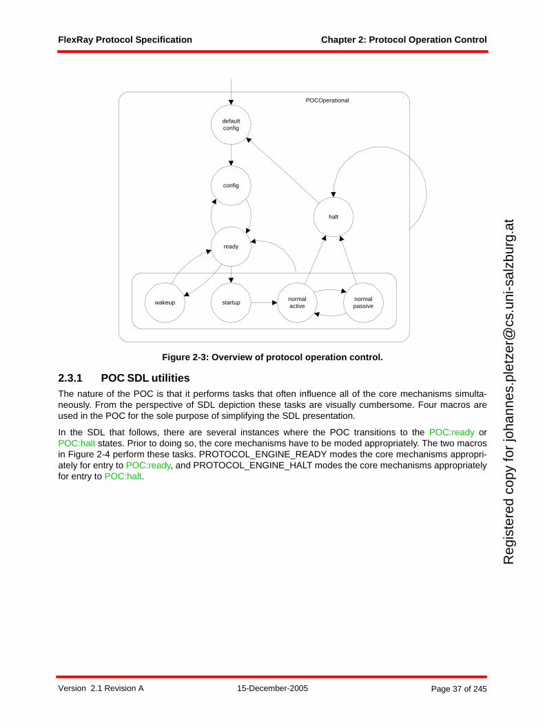
FlexRay Protocol Specification Chapter 2: Protocol Operation Control
Reg
iste
red
copy
for
joha
nnes
.ple
tzer
@cs
.uni
-sal
zbur
g.at
Figure 2-3: Overview of protocol operation control.
2.3.1 POC SDL utilitiesThe nature of the POC is that it performs tasks that often influence all of the core mechanisms simulta-neously. From the perspective of SDL depiction these tasks are visually cumbersome. Four macros areused in the POC for the sole purpose of simplifying the SDL presentation.
In the SDL that follows, there are several instances where the POC transitions to the POC:ready orPOC:halt states. Prior to doing so, the core mechanisms have to be moded appropriately. The two macrosin Figure 2-4 perform these tasks. PROTOCOL_ENGINE_READY modes the core mechanisms appropri-ately for entry to POC:ready, and PROTOCOL_ENGINE_HALT modes the core mechanisms appropriatelyfor entry to POC:halt.
config
ready
halt
defaultconfig
wakeup startupnormalpassive
normalactive
POCOperational
Version 2.1 Revision A 15-December-2005 Page 37 of 245
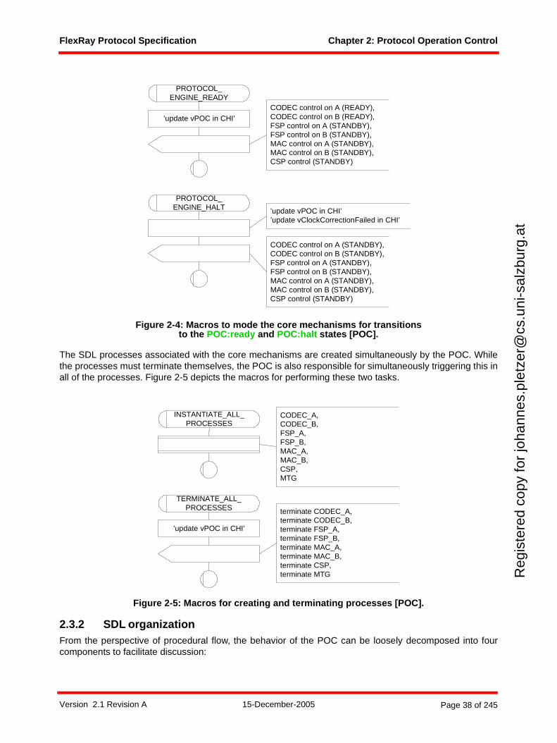
FlexRay Protocol Specification Chapter 2: Protocol Operation Control
Reg
iste
red
copy
for
joha
nnes
.ple
tzer
@cs
.uni
-sal
zbur
g.at
Figure 2-4: Macros to mode the core mechanisms for transitions to the POC:ready and POC:halt states [POC].
The SDL processes associated with the core mechanisms are created simultaneously by the POC. Whilethe processes must terminate themselves, the POC is also responsible for simultaneously triggering this inall of the processes. Figure 2-5 depicts the macros for performing these two tasks.
Figure 2-5: Macros for creating and terminating processes [POC].
2.3.2 SDL organizationFrom the perspective of procedural flow, the behavior of the POC can be loosely decomposed into fourcomponents to facilitate discussion:
PROTOCOL_ENGINE_HALT
CODEC control on A (STANDBY),CODEC control on B (STANDBY),FSP control on A (STANDBY),FSP control on B (STANDBY),MAC control on A (STANDBY),MAC control on B (STANDBY),CSP control (STANDBY)
PROTOCOL_ENGINE_READY
CODEC control on A (READY),CODEC control on B (READY),FSP control on A (STANDBY),FSP control on B (STANDBY),MAC control on A (STANDBY),MAC control on B (STANDBY),CSP control (STANDBY)
’update vPOC in CHI’
’update vPOC in CHI’’update vClockCorrectionFailed in CHI’
TERMINATE_ALL_PROCESSES terminate CODEC_A,
terminate CODEC_B,terminate FSP_A,terminate FSP_B,terminate MAC_A,terminate MAC_B,terminate CSP,terminate MTG
INSTANTIATE_ALL_PROCESSES
CODEC_A,CODEC_B,FSP_A,FSP_B,MAC_A,MAC_B,CSP,MTG
’update vPOC in CHI’
Version 2.1 Revision A 15-December-2005 Page 38 of 245
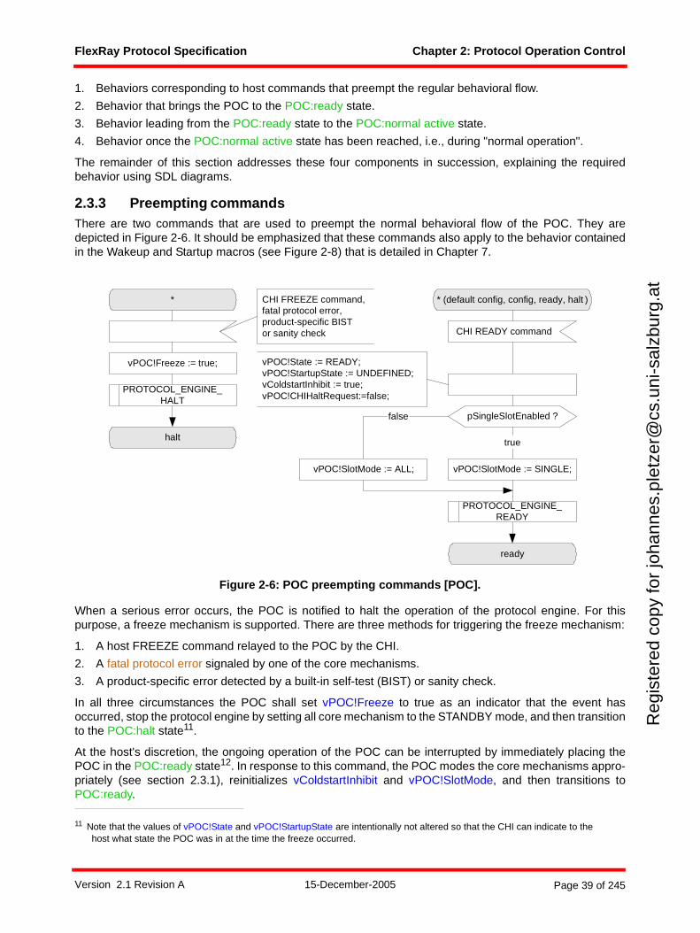
FlexRay Protocol Specification Chapter 2: Protocol Operation Control
Reg
iste
red
copy
for
joha
nnes
.ple
tzer
@cs
.uni
-sal
zbur
g.at
1. Behaviors corresponding to host commands that preempt the regular behavioral flow.
2. Behavior that brings the POC to the POC:ready state.
3. Behavior leading from the POC:ready state to the POC:normal active state.
4. Behavior once the POC:normal active state has been reached, i.e., during "normal operation".
The remainder of this section addresses these four components in succession, explaining the requiredbehavior using SDL diagrams.
2.3.3 Preempting commandsThere are two commands that are used to preempt the normal behavioral flow of the POC. They aredepicted in Figure 2-6. It should be emphasized that these commands also apply to the behavior containedin the Wakeup and Startup macros (see Figure 2-8) that is detailed in Chapter 7.
Figure 2-6: POC preempting commands [POC].
When a serious error occurs, the POC is notified to halt the operation of the protocol engine. For thispurpose, a freeze mechanism is supported. There are three methods for triggering the freeze mechanism:
1. A host FREEZE command relayed to the POC by the CHI.
2. A fatal protocol error signaled by one of the core mechanisms.
3. A product-specific error detected by a built-in self-test (BIST) or sanity check.
In all three circumstances the POC shall set vPOC!Freeze to true as an indicator that the event hasoccurred, stop the protocol engine by setting all core mechanism to the STANDBY mode, and then transitionto the POC:halt state11.
At the host's discretion, the ongoing operation of the POC can be interrupted by immediately placing thePOC in the POC:ready state12. In response to this command, the POC modes the core mechanisms appro-priately (see section 2.3.1), reinitializes vColdstartInhibit and vPOC!SlotMode, and then transitions toPOC:ready.
11 Note that the values of vPOC!State and vPOC!StartupState are intentionally not altered so that the CHI can indicate to the host what state the POC was in at the time the freeze occurred.
* * (default config, config, ready, halt )
CHI READY command
ready
halt
vPOC!Freeze := true;
PROTOCOL_ENGINE_HALT
PROTOCOL_ENGINE_READY
CHI FREEZE command,fatal protocol error,product-specific BISTor sanity check
pSingleSlotEnabled ?
true
false
vPOC!SlotMode := SINGLE;vPOC!SlotMode := ALL;
vPOC!State := READY;vPOC!StartupState := UNDEFINED;vColdstartInhibit := true;vPOC!CHIHaltRequest:=false;
Version 2.1 Revision A 15-December-2005 Page 39 of 245
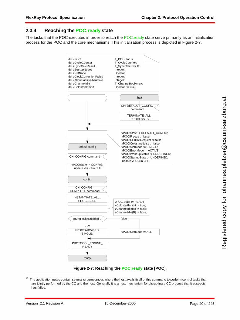
FlexRay Protocol Specification Chapter 2: Protocol Operation Control
Reg
iste
red
copy
for
joha
nnes
.ple
tzer
@cs
.uni
-sal
zbur
g.at
2.3.4 Reaching the POC:ready stateThe tasks that the POC executes in order to reach the POC:ready state serve primarily as an initializationprocess for the POC and the core mechanisms. This initialization process is depicted in Figure 2-7.
Figure 2-7: Reaching the POC:ready state [POC].
12 The application notes contain several circumstances where the host avails itself of this command to perform control tasks that are jointly performed by the CC and the host. Generally it is a host mechanism for disrupting a CC process that it suspects has failed.
default config
CHI CONFIG command
config
CHI CONFIG_COMPLETE command
ready
dcl vPOC T_POCStatus;dcl vCycleCounter T_CycleCounter;dcl zSyncCalcResult T_SyncCalcResult;dcl zStartupNodes Integer;dcl zRefNode Boolean;dcl vClockCorrectionFailed Integer;dcl vAllowPassiveToActive Integer;dcl zChannelIdle T_ChannelBoolArray;dcl vColdstartInhibit Boolean := true;
vPOC!State := DEFAULT_CONFIG;vPOC!Freeze := false;vPOC!CHIHaltRequest := false;vPOC!ColdstartNoise := false;vPOC!SlotMode := SINGLE;vPOC!ErrorMode := ACTIVE;vPOC!WakeupStatus := UNDEFINED;vPOC!StartupState := UNDEFINED;’update vPOC in CHI’
halt
CHI DEFAULT_CONFIGcommand
vPOC!State := CONFIG;’update vPOC in CHI’
TERMINATE_ALL_PROCESSES
PROTOCOL_ENGINE_READY
INSTANTIATE_ALL_PROCESSES
pSingleSlotEnabled ?
true
false
vPOC!SlotMode :=SINGLE;
vPOC!SlotMode := ALL;
vPOC!State := READY;vColdstartInhibit := true;zChannelIdle(A) := false;zChannelIdle(B) := false;
Version 2.1 Revision A 15-December-2005 Page 40 of 245
FlexRay Protocol Specification Chapter 2: Protocol Operation Control
Reg
iste
red
copy
for
joha
nnes
.ple
tzer
@cs
.uni
-sal
zbur
g.at
The POC shall enter the POC:default config state when the CC enters the POC Operational power state(see section 2.1.1). The POC:default config shall also be entered from the POC:halt state if aDEFAULT_CONFIG command is received from the CHI. In the latter case, the POC shall signal the coremechanisms to terminate so that they can be created again as a part of the normal initialization process.
Prior to entering the POC:default config state the POC shall initialize the elements of the vPOC datastructure that is used to communicate the POC status to the CHI. With the exception of vPOC!SlotMode,the values assumed by the vPOC elements are obvious initial values and are depicted in Figure 2-7. Theinitial value of vPOC!SlotMode is defaulted to SINGLE until the configuration process is carried out to set itto the value desired by the host.
In the POC:default config state the POC awaits the explicit command from the host to enable configuration.The POC shall enter the POC:config state in response to the CONFIG command. Configuration of the CCis only allowed in the POC:config state and this state can only be entered with an explicit CONFIG commandissued while the POC is in the POC:default config state or the POC:ready state (see section 2.3.5).
In the POC:config state the host configures the CC. The host is responsible for verifying this configurationand only allowing the initialization to proceed when a proper configuration is verified. For this purpose, anexplicit CONFIG_COMPLETE command is required for the POC to progress from the POC:config state.
The POC shall transition to the POC:ready state in response to the CONFIG_COMPLETE command. Onthis transition, the POC shall create all of the core mechanism processes, incorporating the configurationvalues that were set in the POC:config state. It shall then update vPOC to reflect the new state, the newlyconfigured value of slot mode13, and the initial value of the vColdstartInhibit. It shall then command all ofthe core mechanisms to their appropriate mode (see section 2.3.1). The POC then transitions to thePOC:ready state.
2.3.5 Reaching the POC:normal active stateFollowing the initialization sequence (see section 2.3.4) the CC resides in the POC:ready state (see Figure2-8). From this state the CC is able to perform the necessary tasks to start or join an actively communicatingcluster. There are three POC actions that can take place, each of which is initiated by a specific commandfrom the CHI. These commands are WAKEUP, RUN, and CONFIG.
13 The value is determined by the node configuration, pSingleSlotEnabled, a Boolean used to indicate whether the single slot mode is enabled. This supports an optional strategy to limit frame transmissions following startup to a single designated frame until the host confirms that the node is synchronized to the cluster and enables the remaining transmissions with an ALL_SLOTS command (see section 2.3.6.1).
Version 2.1 Revision A 15-December-2005 Page 41 of 245
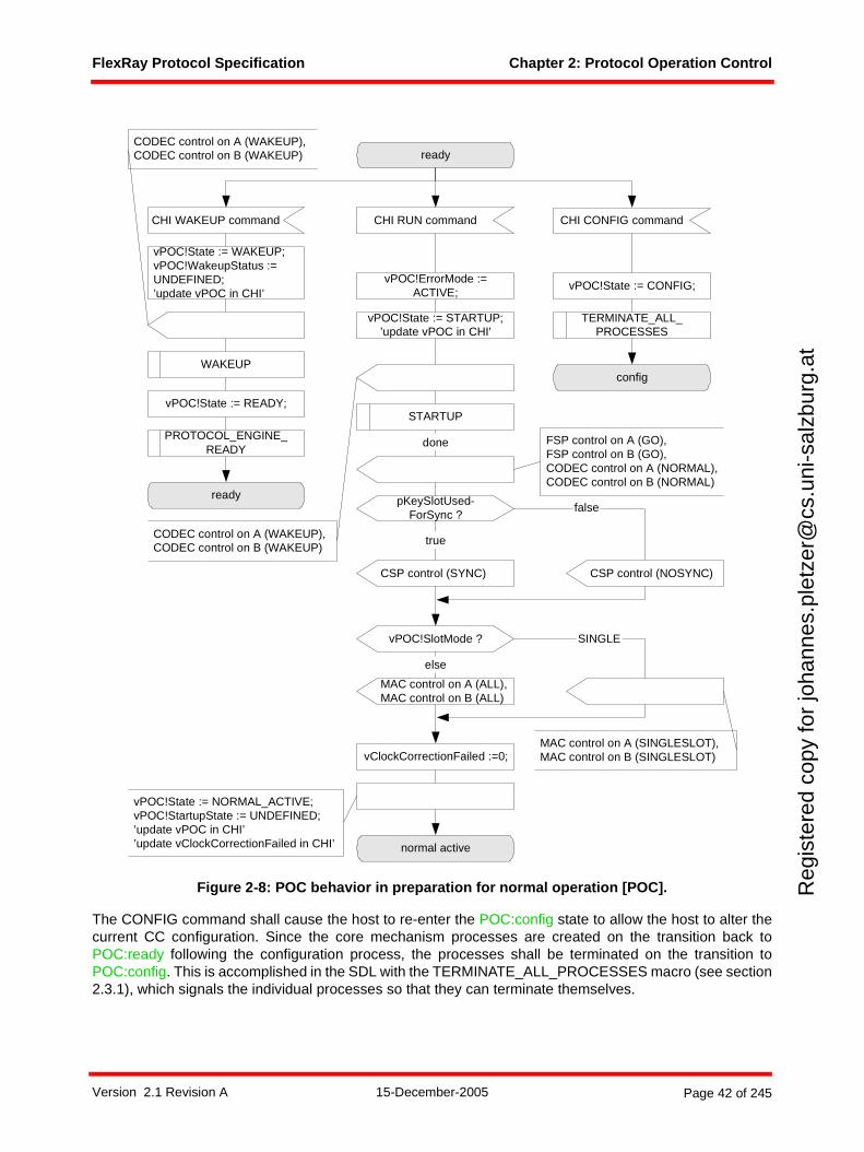
FlexRay Protocol Specification Chapter 2: Protocol Operation Control
Reg
iste
red
copy
for
joha
nnes
.ple
tzer
@cs
.uni
-sal
zbur
g.at
Figure 2-8: POC behavior in preparation for normal operation [POC].
The CONFIG command shall cause the host to re-enter the POC:config state to allow the host to alter thecurrent CC configuration. Since the core mechanism processes are created on the transition back toPOC:ready following the configuration process, the processes shall be terminated on the transition toPOC:config. This is accomplished in the SDL with the TERMINATE_ALL_PROCESSES macro (see section2.3.1), which signals the individual processes so that they can terminate themselves.
config
CSP control (SYNC)
ready
CHI RUN commandCHI WAKEUP command CHI CONFIG command
vPOC!ErrorMode :=ACTIVE;
WAKEUP
STARTUP
CSP control (NOSYNC)
pKeySlotUsed-ForSync ?
vPOC!SlotMode ?
MAC control on A (ALL),MAC control on B (ALL)
else
SINGLE
true
false
vClockCorrectionFailed :=0;
normal active
done
ready
CODEC control on A (WAKEUP),CODEC control on B (WAKEUP)
PROTOCOL_ENGINE_READY
vPOC!State := READY;
vPOC!State := CONFIG;
TERMINATE_ALL_PROCESSES
vPOC!State := WAKEUP;vPOC!WakeupStatus :=UNDEFINED;’update vPOC in CHI’
vPOC!State := STARTUP;’update vPOC in CHI’
vPOC!State := NORMAL_ACTIVE;vPOC!StartupState := UNDEFINED;’update vPOC in CHI’’update vClockCorrectionFailed in CHI’
MAC control on A (SINGLESLOT),MAC control on B (SINGLESLOT)
FSP control on A (GO),FSP control on B (GO),CODEC control on A (NORMAL),CODEC control on B (NORMAL)
CODEC control on A (WAKEUP),CODEC control on B (WAKEUP)
Version 2.1 Revision A 15-December-2005 Page 42 of 245
FlexRay Protocol Specification Chapter 2: Protocol Operation Control
Reg
iste
red
copy
for
joha
nnes
.ple
tzer
@cs
.uni
-sal
zbur
g.at
The WAKEUP command shall cause the POC to commence the wakeup procedure in accordance with theconfiguration loaded into the CC when it was previously configured. This procedure is described in detail insection 7.1, and is represented in Figure 2-8 by the WAKEUP macro invocation. On completion of thewakeup procedure, the POC shall mode all the core mechanisms appropriately for POC:ready (see section2.3.1) and return to the POC:ready state.
The RUN command shall cause the POC to commence a sequence of tasks to bring the POC to normaloperation, i.e. the POC:normal active state. First, all internal status variables are reset to their startingvalues14. Then the startup procedure is executed. In Figure 2-8 this is represented by the STARTUP macroinvocation. This procedure is described in detail in section 7.2. This procedure modes the core mechanismsappropriately to perform the sequence of tasks necessary for the node to start or enter an actively commu-nicating cluster.
The startup procedure results in the node being synchronized to the timing of the cluster. At the end of thecommunication cycle, the POC shall mode the core mechanisms depending on the values ofvPOC!SlotMode and the configuration pKeySlotUsedForSync (see Appendix B) as depicted in Figure 2-8:
1. The CODEC mechanism shall be moded to NORMAL and the FSP mechanism shall be moded to GO for both channels.
2. If the node is a sync node (including coldstart nodes) (pKeySlotUsedForSync is true) CSP shall be moded to SYNC mode. Otherwise, CSP shall be moded to NOSYNC.
3. If the node is currently in single slot mode (vPOC!SlotMode is SINGLE), then the POC shall mode the MAC to SINGLESLOT mode on both channels. If the node is not currently in single slot mode (vPOC!SlotMode is ALL), then the POC shall mode the MAC to ALL mode on both channels.
The POC shall then enter the POC:normal active state.
2.3.5.1 Wakeup and startup support
As indicated above, the Wakeup and Startup procedures are performed in logical extensions of the POCthat are embodied in the WAKEUP and STARTUP macros. The POC behavior captured in those macros isdocumented in Chapter 7 and is largely self-contained. However, there are two exceptions and they aredepicted in Figure 2-9.
14 This is necessary because the POC:ready state may have been entered due to a READY command from the CHI that caused the POC to enter POC:ready from a state where the status variables had already been altered (see section 2.3.2).
Version 2.1 Revision A 15-December-2005 Page 43 of 245
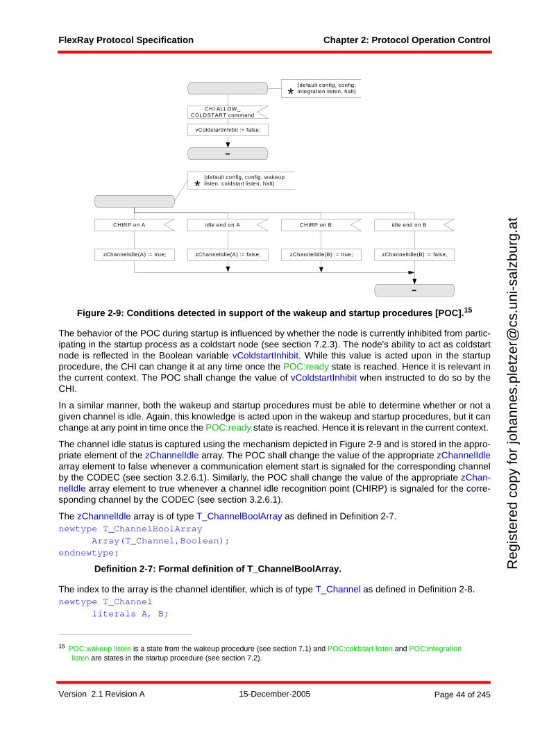
FlexRay Protocol Specification Chapter 2: Protocol Operation Control
Reg
iste
red
copy
for
joha
nnes
.ple
tzer
@cs
.uni
-sal
zbur
g.at
Figure 2-9: Conditions detected in support of the wakeup and startup procedures [POC].15
The behavior of the POC during startup is influenced by whether the node is currently inhibited from partic-ipating in the startup process as a coldstart node (see section 7.2.3). The node's ability to act as coldstartnode is reflected in the Boolean variable vColdstartInhibit. While this value is acted upon in the startupprocedure, the CHI can change it at any time once the POC:ready state is reached. Hence it is relevant inthe current context. The POC shall change the value of vColdstartInhibit when instructed to do so by theCHI.
In a similar manner, both the wakeup and startup procedures must be able to determine whether or not agiven channel is idle. Again, this knowledge is acted upon in the wakeup and startup procedures, but it canchange at any point in time once the POC:ready state is reached. Hence it is relevant in the current context.
The channel idle status is captured using the mechanism depicted in Figure 2-9 and is stored in the appro-priate element of the zChannelIdle array. The POC shall change the value of the appropriate zChannelIdlearray element to false whenever a communication element start is signaled for the corresponding channelby the CODEC (see section 3.2.6.1). Similarly, the POC shall change the value of the appropriate zChan-nelIdle array element to true whenever a channel idle recognition point (CHIRP) is signaled for the corre-sponding channel by the CODEC (see section 3.2.6.1).
The zChannelIdle array is of type T_ChannelBoolArray as defined in Definition 2-7.newtype T_ChannelBoolArray
Array(T_Channel,Boolean);endnewtype;
Definition 2-7: Formal definition of T_ChannelBoolArray.
The index to the array is the channel identifier, which is of type T_Channel as defined in Definition 2-8.newtype T_Channel
literals A, B;
15 POC:wakeup listen is a state from the wakeup procedure (see section 7.1) and POC:coldstart listen and POC:integration listen are states in the startup procedure (see section 7.2).
CHI ALLOW_COLDSTART command
-
CHIRP on A idle end on A CHIRP on B
-
zChannelIdle(A) := true; zChannelIdle(A) := false; zChannelIdle(B) := true;
vColdstartInhibit := false;
(default config, config, wakeuplisten, coldstart listen, halt) *
(default config, config,integration listen, halt) *
idle end on B
zChannelIdle(B) := false;
Version 2.1 Revision A 15-December-2005 Page 44 of 245
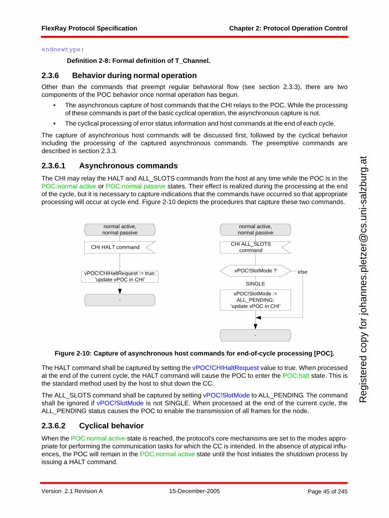
FlexRay Protocol Specification Chapter 2: Protocol Operation Control
Reg
iste
red
copy
for
joha
nnes
.ple
tzer
@cs
.uni
-sal
zbur
g.at
endnewtype;
Definition 2-8: Formal definition of T_Channel.
2.3.6 Behavior during normal operationOther than the commands that preempt regular behavioral flow (see section 2.3.3), there are twocomponents of the POC behavior once normal operation has begun.
• The asynchronous capture of host commands that the CHI relays to the POC. While the processingof these commands is part of the basic cyclical operation, the asynchronous capture is not.
• The cyclical processing of error status information and host commands at the end of each cycle.
The capture of asynchronous host commands will be discussed first, followed by the cyclical behaviorincluding the processing of the captured asynchronous commands. The preemptive commands aredescribed in section 2.3.3.
2.3.6.1 Asynchronous commands
The CHI may relay the HALT and ALL_SLOTS commands from the host at any time while the POC is in thePOC:normal active or POC:normal passive states. Their effect is realized during the processing at the endof the cycle, but it is necessary to capture indications that the commands have occurred so that appropriateprocessing will occur at cycle end. Figure 2-10 depicts the procedures that capture these two commands.
Figure 2-10: Capture of asynchronous host commands for end-of-cycle processing [POC].
The HALT command shall be captured by setting the vPOC!CHIHaltRequest value to true. When processedat the end of the current cycle, the HALT command will cause the POC to enter the POC:halt state. This isthe standard method used by the host to shut down the CC.
The ALL_SLOTS command shall be captured by setting vPOC!SlotMode to ALL_PENDING. The commandshall be ignored if vPOC!SlotMode is not SINGLE. When processed at the end of the current cycle, theALL_PENDING status causes the POC to enable the transmission of all frames for the node.
2.3.6.2 Cyclical behavior
When the POC:normal active state is reached, the protocol's core mechanisms are set to the modes appro-priate for performing the communication tasks for which the CC is intended. In the absence of atypical influ-ences, the POC will remain in the POC:normal active state until the host initiates the shutdown process byissuing a HALT command.
normal active,normal passive
CHI HALT command
vPOC!CHIHaltRequest := true;’update vPOC in CHI’
-
normal active,normal passive
CHI ALL_SLOTScommand
vPOC!SlotMode :=ALL_PENDING;
’update vPOC in CHI’
-
SINGLE
vPOC!SlotMode ? else
Version 2.1 Revision A 15-December-2005 Page 45 of 245
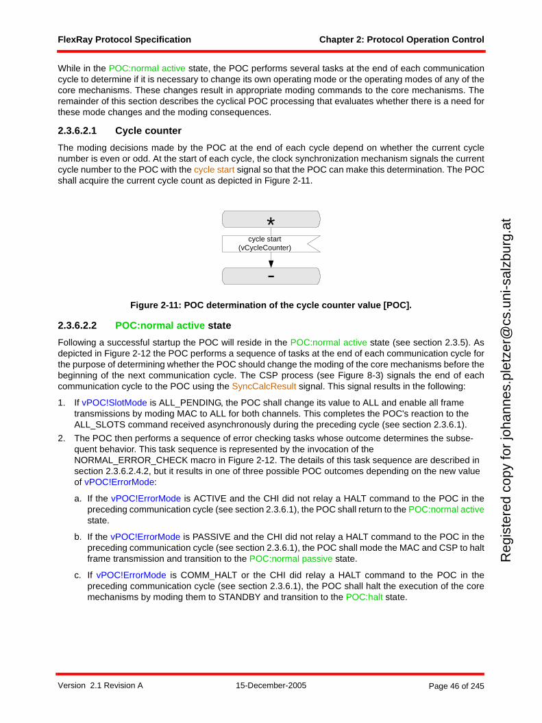
FlexRay Protocol Specification Chapter 2: Protocol Operation Control
Reg
iste
red
copy
for
joha
nnes
.ple
tzer
@cs
.uni
-sal
zbur
g.at
While in the POC:normal active state, the POC performs several tasks at the end of each communicationcycle to determine if it is necessary to change its own operating mode or the operating modes of any of thecore mechanisms. These changes result in appropriate moding commands to the core mechanisms. Theremainder of this section describes the cyclical POC processing that evaluates whether there is a need forthese mode changes and the moding consequences.
2.3.6.2.1 Cycle counter
The moding decisions made by the POC at the end of each cycle depend on whether the current cyclenumber is even or odd. At the start of each cycle, the clock synchronization mechanism signals the currentcycle number to the POC with the cycle start signal so that the POC can make this determination. The POCshall acquire the current cycle count as depicted in Figure 2-11.
Figure 2-11: POC determination of the cycle counter value [POC].
2.3.6.2.2 POC:normal active state
Following a successful startup the POC will reside in the POC:normal active state (see section 2.3.5). Asdepicted in Figure 2-12 the POC performs a sequence of tasks at the end of each communication cycle forthe purpose of determining whether the POC should change the moding of the core mechanisms before thebeginning of the next communication cycle. The CSP process (see Figure 8-3) signals the end of eachcommunication cycle to the POC using the SyncCalcResult signal. This signal results in the following:
1. If vPOC!SlotMode is ALL_PENDING, the POC shall change its value to ALL and enable all frame transmissions by moding MAC to ALL for both channels. This completes the POC's reaction to the ALL_SLOTS command received asynchronously during the preceding cycle (see section 2.3.6.1).
2. The POC then performs a sequence of error checking tasks whose outcome determines the subse-quent behavior. This task sequence is represented by the invocation of the NORMAL_ERROR_CHECK macro in Figure 2-12. The details of this task sequence are described in section 2.3.6.2.4.2, but it results in one of three possible POC outcomes depending on the new value of vPOC!ErrorMode:
a. If the vPOC!ErrorMode is ACTIVE and the CHI did not relay a HALT command to the POC in thepreceding communication cycle (see section 2.3.6.1), the POC shall return to the POC:normal activestate.
b. If the vPOC!ErrorMode is PASSIVE and the CHI did not relay a HALT command to the POC in thepreceding communication cycle (see section 2.3.6.1), the POC shall mode the MAC and CSP to haltframe transmission and transition to the POC:normal passive state.
c. If vPOC!ErrorMode is COMM_HALT or the CHI did relay a HALT command to the POC in thepreceding communication cycle (see section 2.3.6.1), the POC shall halt the execution of the coremechanisms by moding them to STANDBY and transition to the POC:halt state.
cycle start(vCycleCounter)
-
*
Version 2.1 Revision A 15-December-2005 Page 46 of 245
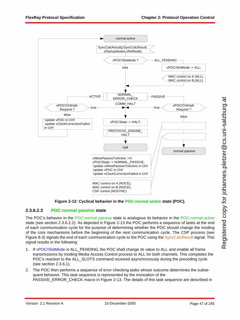
FlexRay Protocol Specification Chapter 2: Protocol Operation Control
Reg
iste
red
copy
for
joha
nnes
.ple
tzer
@cs
.uni
-sal
zbur
g.at
Figure 2-12: Cyclical behavior in the POC:normal active state [POC].
2.3.6.2.3 POC:normal passive state
The POC's behavior in the POC:normal passive state is analogous its behavior in the POC:normal activestate (see section 2.3.6.2.2). As depicted in Figure 2-13 the POC performs a sequence of tasks at the endof each communication cycle for the purpose of determining whether the POC should change the modingof the core mechanisms before the beginning of the next communication cycle. The CSP process (seeFigure 8-3) signals the end of each communication cycle to the POC using the SyncCalcResult signal. Thissignal results in the following:
1. If vPOC!SlotMode is ALL_PENDING, the POC shall change its value to ALL and enable all frame transmissions by moding Media Access Control process to ALL for both channels. This completes the POC's reaction to the ALL_SLOTS command received asynchronously during the preceding cycle (see section 2.3.6.1).
2. The POC then performs a sequence of error checking tasks whose outcome determines the subse-quent behavior. This task sequence is represented by the invocation of the PASSIVE_ERROR_CHECK macro in Figure 2-13. The details of this task sequence are described in
normal active
vPOC!CHIHalt-Request ? true
halt
vPOC!SlotMode ?
vPOC!SlotMode := ALL;
ALL_PENDING
else
COMM_HALT
NORMAL_ERROR_CHECK
PASSIVE
normal passive
ACTIVE
PROTOCOL_ENGINE_HALT
MAC control on A (ALL),MAC control on B (ALL)
vPOC!CHIHalt-Request ?
false
true
vPOC!State := HALT;
SyncCalcResult(zSyncCalcResult,zStartupNodes,zRefNode)
MAC control on A (NOCE),MAC control on B (NOCE),CSP control (NOSYNC)
vAllowPassiveToActive :=0;vPOC!State := NORMAL_PASSIVE;’update vAllowPassiveToActive in CHI’’update vPOC in CHI’’update vClockCorrectionFailed in CHI’
’update vPOC in CHI’’update vClockCorrectionFailedin CHI’
false
Version 2.1 Revision A 15-December-2005 Page 47 of 245
FlexRay Protocol Specification Chapter 2: Protocol Operation Control
Reg
iste
red
copy
for
joha
nnes
.ple
tzer
@cs
.uni
-sal
zbur
g.at
section 2.3.6.2.4.3, but it results in one of three possible POC outcomes depending on the new value of vPOC!ErrorMode:
a. If the vPOC!ErrorMode is ACTIVE and the CHI did not relay a HALT command to the POC in thepreceding communication cycle (see section 2.3.6.1), the POC shall mode the MAC and CSPmechanisms to support resumption of frame transmission based on whether the node is a sync node(pKeySlotUsedForSync is true) and whether the node is currently in single slot mode, and thentransition to the POC:normal active state.
b. If the vPOC!ErrorMode is PASSIVE and the CHI did not relay a HALT command to the POC in thepreceding communication cycle (see section 2.3.6.1), the POC shall return to the POC:normalpassive state.
c. If vPOC!ErrorMode is COMM_HALT or the CHI did relay a HALT command to the POC in thepreceding communication cycle (see section 2.3.6.1), the POC shall stop the execution of the coremechanisms by moding them to STANDBY and transition to the POC:halt state.
Version 2.1 Revision A 15-December-2005 Page 48 of 245
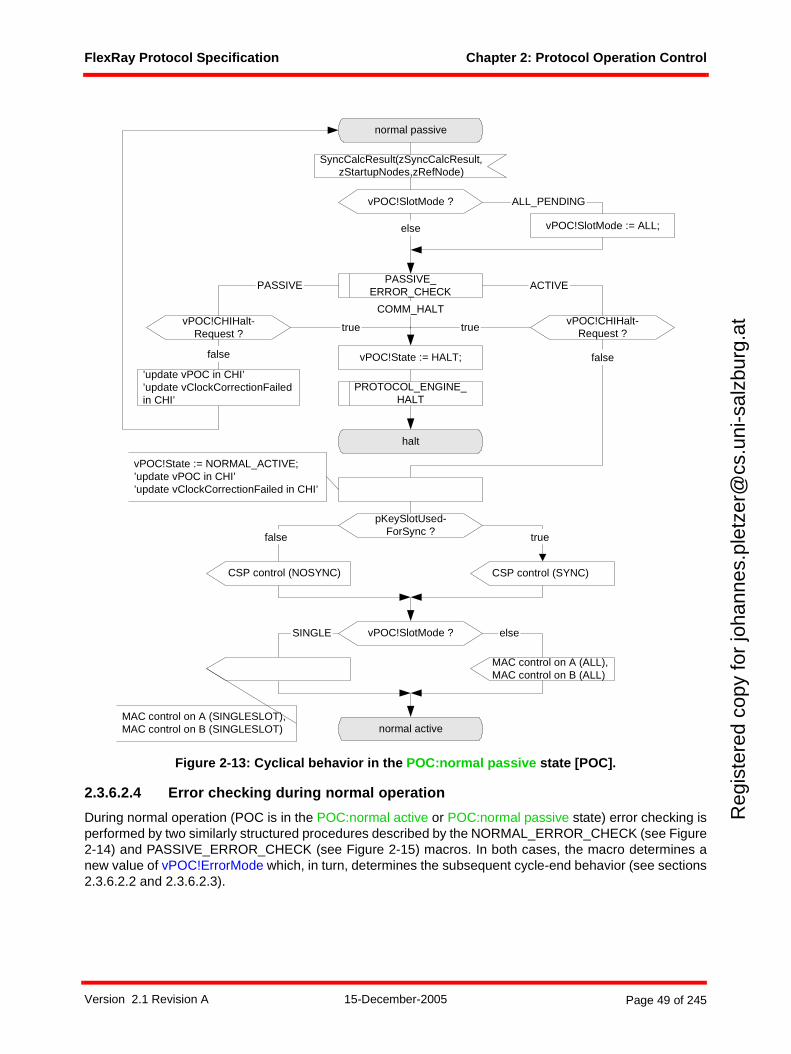
FlexRay Protocol Specification Chapter 2: Protocol Operation Control
Reg
iste
red
copy
for
joha
nnes
.ple
tzer
@cs
.uni
-sal
zbur
g.at
Figure 2-13: Cyclical behavior in the POC:normal passive state [POC].
2.3.6.2.4 Error checking during normal operation
During normal operation (POC is in the POC:normal active or POC:normal passive state) error checking isperformed by two similarly structured procedures described by the NORMAL_ERROR_CHECK (see Figure2-14) and PASSIVE_ERROR_CHECK (see Figure 2-15) macros. In both cases, the macro determines anew value of vPOC!ErrorMode which, in turn, determines the subsequent cycle-end behavior (see sections2.3.6.2.2 and 2.3.6.2.3).
normal passive
SyncCalcResult(zSyncCalcResult,zStartupNodes,zRefNode)
vPOC!CHIHalt-Request ?
halt
vPOC!SlotMode ?
vPOC!SlotMode := ALL;
ALL_PENDING
else
COMM_HALT
PASSIVE_ERROR_CHECK
ACTIVE
normal active
PASSIVE
vPOC!CHIHalt-Request ?
falsevPOC!State := HALT;
PROTOCOL_ENGINE_HALT
truetrue
CSP control (SYNC)CSP control (NOSYNC)
vPOC!SlotMode ?
MAC control on A (ALL),MAC control on B (ALL)
elseSINGLE
false
MAC control on A (SINGLESLOT),MAC control on B (SINGLESLOT)
pKeySlotUsed-ForSync ? true
’update vPOC in CHI’’update vClockCorrectionFailedin CHI’
false
vPOC!State := NORMAL_ACTIVE;’update vPOC in CHI’’update vClockCorrectionFailed in CHI’
Version 2.1 Revision A 15-December-2005 Page 49 of 245
FlexRay Protocol Specification Chapter 2: Protocol Operation Control
Reg
iste
red
copy
for
joha
nnes
.ple
tzer
@cs
.uni
-sal
zbur
g.at
2.3.6.2.4.1 Error checking overview
At the end of each communication cycle CSP communicates the error consequences of the clock synchro-nization mechanism's rate and offset calculations. In the SDL this is accomplished with the SyncCalcResultsignal whose first argument, zSyncCalcResult, assumes one of three values:
1. WITHIN_BOUNDS indicates that the calculations resulted in no errors.
2. MISSING_TERM indicates that either the rate or offset correction could not be calculated.
3. EXCEEDS_BOUNDS indicates that either the rate or offset correction term calculated was deemed too large when compared to the calibrated limits.
The consequences of the EXCEEDS_BOUNDS value are processed in every cycle. The other two resultsare only processed at the end of odd cycles.
The error checking behavior is detailed in sections 2.3.6.2.4.2 and 2.3.6.2.4.3. A number of configurationalternatives and the need to verify cycle timing before resuming communication influence the detailed errorchecking behavior. However, the basic concept can be grasped by considering the behavior in the absenceof these considerations. In the absence of these influences, the processing path is determined by thevalue of zSyncCalcResult as follows:
1. In all cycles (even or odd), zSyncCalcResult = EXCEEDS_BOUNDS causes the POC to transition to the POC:halt state.
2. In odd cycles, zSyncCalcResult = WITHIN_BOUNDS causes the POC to stay in, or transition to, the POC:normal active state.
3. In odd cycles, if zSyncCalcResult = MISSING_TERM
a. The POC will transition to the POC:halt state if the MISSING_TERM value has persisted for at leastgMaxWithoutClockCorrectionFatal odd cycles.
b. The POC will transition to (or remain in) the POC:normal passive state if the MISSING_TERM valuehas persisted for at least gMaxWithoutClockCorrectionPassive, but less than gMaxWithoutClock-CorrectionFatal odd cycles.
c. Otherwise the POC stays in the POC:normal active state.
2.3.6.2.4.2 Error checking details for the POC:normal active state
The zSyncCalcResult value obtained from CSP is used to determine the new vPOC!ErrorMode as depictedin Figure 2-14.
1. If zSyncCalcResult is WITHIN_BOUNDS, the vPOC!ErrorMode remains ACTIVE.
2. If zSyncCalcResult is EXCEEDS_BOUNDS:
a. If the node is configured to allow communication to be halted due to severe clock calculation errors(pAllowHaltDueToClock is true), then the vPOC!ErrorMode is set to COMM_HALT.
b. If the node is configured not to allow communication to be halted due to severe clock calculationerrors (pAllowHaltDueToClock is false), then the vPOC!ErrorMode is set to PASSIVE.
3. If zSyncCalcResult is MISSING_TERM and the cycle is even, the condition is ignored and vPOC!ErrorMode remains ACTIVE.
4. If zSyncCalcResult is MISSING_TERM and the cycle is odd the behavior is determined by how many consecutive odd cycles (vClockCorrectionFailed) have yielded MISSING_TERM.
a. If vClockCorrectionFailed < gMaxWithoutClockCorrectionPassive, then the vPOC!ErrorModeremains ACTIVE.
b. If gMaxWithoutClockCorrectionPassive <= vClockCorrectionFailed < gMaxWithoutClockCorrection-Fatal, then the vPOC!ErrorMode is set to PASSIVE.
c. If vClockCorrectionFailed >= gMaxWithoutClockCorrectionFatal and
Version 2.1 Revision A 15-December-2005 Page 50 of 245
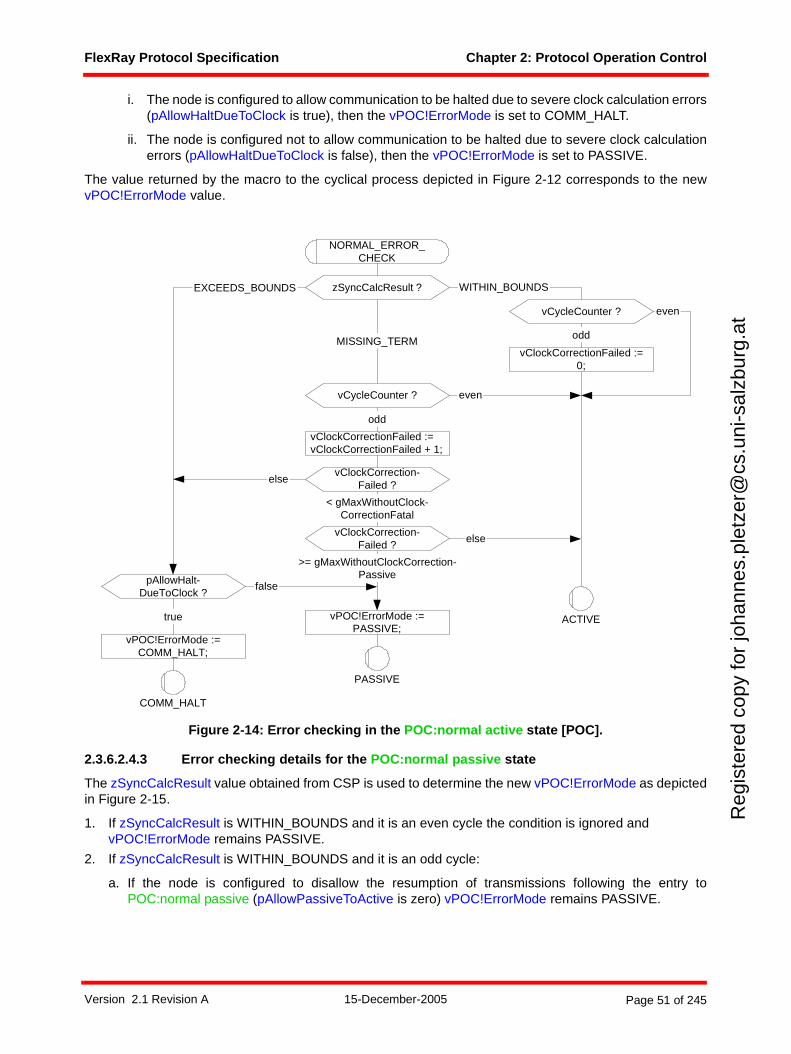
FlexRay Protocol Specification Chapter 2: Protocol Operation Control
Reg
iste
red
copy
for
joha
nnes
.ple
tzer
@cs
.uni
-sal
zbur
g.at
i. The node is configured to allow communication to be halted due to severe clock calculation errors(pAllowHaltDueToClock is true), then the vPOC!ErrorMode is set to COMM_HALT.
ii. The node is configured not to allow communication to be halted due to severe clock calculationerrors (pAllowHaltDueToClock is false), then the vPOC!ErrorMode is set to PASSIVE.
The value returned by the macro to the cyclical process depicted in Figure 2-12 corresponds to the newvPOC!ErrorMode value.
Figure 2-14: Error checking in the POC:normal active state [POC].
2.3.6.2.4.3 Error checking details for the POC:normal passive state
The zSyncCalcResult value obtained from CSP is used to determine the new vPOC!ErrorMode as depictedin Figure 2-15.
1. If zSyncCalcResult is WITHIN_BOUNDS and it is an even cycle the condition is ignored and vPOC!ErrorMode remains PASSIVE.
2. If zSyncCalcResult is WITHIN_BOUNDS and it is an odd cycle:
a. If the node is configured to disallow the resumption of transmissions following the entry toPOC:normal passive (pAllowPassiveToActive is zero) vPOC!ErrorMode remains PASSIVE.
vClockCorrection-Failed ?
MISSING_TERM
PASSIVE
pAllowHalt-DueToClock ?
ACTIVE
else
>= gMaxWithoutClockCorrection-Passive
vClockCorrection-Failed ?
zSyncCalcResult ?
COMM_HALT
< gMaxWithoutClock-CorrectionFatal
vClockCorrectionFailed :=vClockCorrectionFailed + 1;
EXCEEDS_BOUNDS
NORMAL_ERROR_CHECK
WITHIN_BOUNDS
false
true
vPOC!ErrorMode :=COMM_HALT;
vPOC!ErrorMode :=PASSIVE;
vCycleCounter ?
odd
vClockCorrectionFailed :=0;
vCycleCounter ?
odd
even
else
even
Version 2.1 Revision A 15-December-2005 Page 51 of 245
FlexRay Protocol Specification Chapter 2: Protocol Operation Control
Reg
iste
red
copy
for
joha
nnes
.ple
tzer
@cs
.uni
-sal
zbur
g.at
b. If the node is configured to allow the resumption of transmissions following the entry to POC:normalpassive (pAllowPassiveToActive is nonzero) the behavior is determined by how many consecutiveodd cycles have yielded WITHIN_BOUNDS.
i. If less than pAllowPassiveToActive consecutive odd cycles have yielded WITHIN_BOUNDS,then the vPOC!ErrorMode remains PASSIVE.
ii. If at least pAllowPassiveToActive consecutive odd cycles have yielded WITHIN_BOUNDS, thevPOC!ErrorMode depends on the number (zStartupNodes) of startup frame pairs observed in thepreceding double cycle.
A. If the node has seen more than one startup frame pair (zStartupNodes > 1) then thevPOC!ErrorMode is set to ACTIVE.
B. If the node has seen only one startup frame pair (zStartupNodes = 1) and if the node is acoldstart node (pKeySlotUsedForStartup = true) then the vPOC!ErrorMode is set to ACTIVE.
C. If neither of the preceding two conditions is met then the vPOC!ErrorMode remains PASSIVE.
3. If zSyncCalcResult is EXCEEDS_BOUNDS:
a. If the node is configured to allow communication to be halted due to severe clock calculation errors(pAllowHaltDueToClock is true), then the vPOC!ErrorMode is set to COMM_HALT.
b. If the node is configured not to allow communication to be halted due to severe clock calculationerrors (pAllowHaltDueToClock is false), then the vPOC!ErrorMode remains PASSIVE.
4. If zSyncCalcResult is MISSING_TERM and the cycle is even, the condition is ignored and vPOC!ErrorMode remains PASSIVE.
5. If zSyncCalcResult is MISSING_TERM and the cycle is odd, then the behavior is determined by how many consecutive odd cycles have yielded MISSING_TERM.
a. If at least gMaxWithoutClockCorrectionFatal consecutive odd cycles have yielded MISSING_TERM,and
i. The node is configured to allow communication to be halted due to severe clock calculation errors(pAllowHaltDueToClock is true), then the vPOC!ErrorMode is set to COMM_HALT.
ii. The node is configured not to allow communication to be halted due to severe clock calculationerrors (pAllowHaltDueToClock is false), then the vPOC!ErrorMode remains PASSIVE.
b. If less than gMaxWithoutClockCorrectionFatal consecutive odd cycles have yieldedMISSING_TERM then the vPOC!ErrorMode remains PASSIVE.
The value returned by the macro to the cyclical process depicted in Figure 2-13 corresponds to the newvPOC!ErrorMode value.
Version 2.1 Revision A 15-December-2005 Page 52 of 245
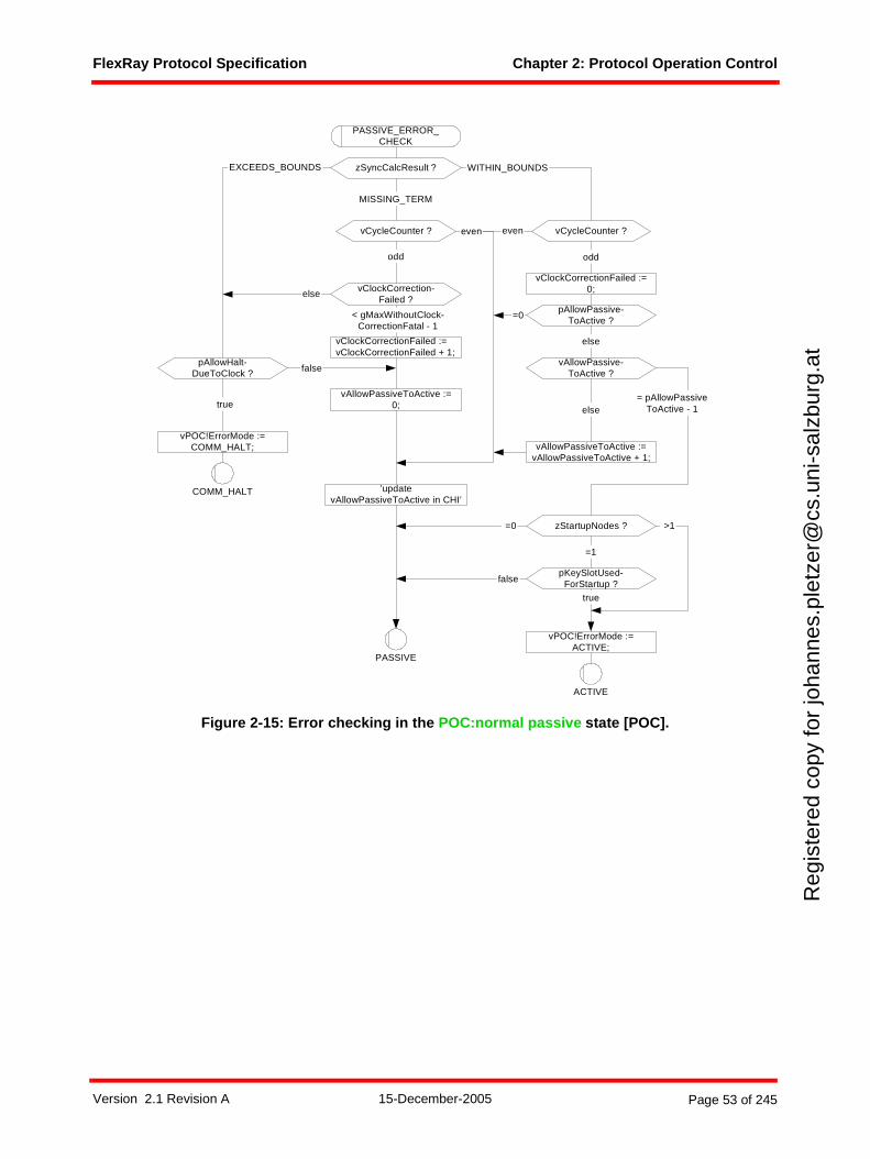
FlexRay Protocol Specification Chapter 2: Protocol Operation Control
Reg
iste
red
copy
for
joha
nnes
.ple
tzer
@cs
.uni
-sal
zbur
g.at
Figure 2-15: Error checking in the POC:normal passive state [POC].
true
vClockCorrection-Failed ?
< gMaxWithoutClock-CorrectionFatal - 1
vClockCorrectionFailed :=vClockCorrectionFailed + 1;
pAllowHalt-DueToClock ?
true
else
COMM_HALT
zStartupNodes ?
false
pKeySlotUsed-ForStartup ?
=1
>1
vAllowPassive-ToActive ?
= pAllowPassiveToActive - 1
vClockCorrectionFailed :=0;
WITHIN_BOUNDSzSyncCalcResult ?
ACTIVE
PASSIVE_ERROR_CHECK
MISSING_TERM
PASSIVE
EXCEEDS_BOUNDS
=0
=0
false
vPOC!ErrorMode :=COMM_HALT;
vPOC!ErrorMode :=ACTIVE;
vAllowPassiveToActive :=vAllowPassiveToActive + 1;
vAllowPassiveToActive :=0; else
vCycleCounter ? even
odd
pAllowPassive-ToActive ?
else
vCycleCounter ?even
odd
’updatevAllowPassiveToActive in CHI’
Version 2.1 Revision A 15-December-2005 Page 53 of 245
FlexRay Protocol Specification Chapter 3: Coding and Decoding
Reg
iste
red
copy
for
joha
nnes
.ple
tzer
@cs
.uni
-sal
zbur
g.at
Chapter 3Coding and Decoding
This chapter defines how the node performs frame and symbol coding and decoding.
3.1 Principles
This chapter describes the coding and decoding behavior of the TxD, RxD, and TxEN interface signalsbetween the communication controller and the bus driver.
A node may support up to two independent physical layer channels, identified as channel A and channel B.Refer to section 1.9.4 for additional information on the interface between the CC and the BD. Since theFlexRay protocol is independent from the underlying physical layer, the description in this chapter assumesa binary medium with two distinct levels, called HIGH and LOW.16 A bit stream generated from these twolevels is called a communication element (CE).
A node shall use a non-return to zero (NRZ) signaling method for coding and decoding of a CE. This meansthat the generated bit level is either LOW or HIGH during the entire bit time gdBit.
The node processes bit streams present on the physical media, extracts frame and symbol information, andpasses this information to the relevant FlexRay processes.
3.2 Description
In order to support two channels each node must implement two sets of independent coding and decodingprocesses, one for channel A and another for channel B. The subsequent paragraphs of this chapter specifythe function of the coding and decoding for channel A. It is assumed that whenever a channel-specificprocess is defined for channel A there is another, essentially identical, process defined for channel B, eventhough this process is not explicitly described in the specification.
The description of the coding and decoding behavior is contained in three processes. These processes arethe main coding and decoding process (CODEC) and the following two sub-processes:
1. Bit strobing process (BITSTRB).
2. Wakeup pattern decoding process (WUPDEC).
The POC is responsible for creating the CODEC process before entering the POC:ready state. Once instan-tiated, the CODEC process is responsible for creating and terminating the subprocesses. The POC isresponsible for sending a signal that causes a termination of the CODEC process.
The relationships between the coding/decoding and the other core mechanisms are depicted in Figure 3-117.
16 Detailed bus state definitions may be found in the appropriate physical layer specification ([EPL05], for example).17 The dark lines represent data flows between mechanisms that are relevant to this chapter. The lighter gray lines are relevant
to the protocol, but not to this chapter.
Version 2.1 Revision A 15-December-2005 Page 54 of 245
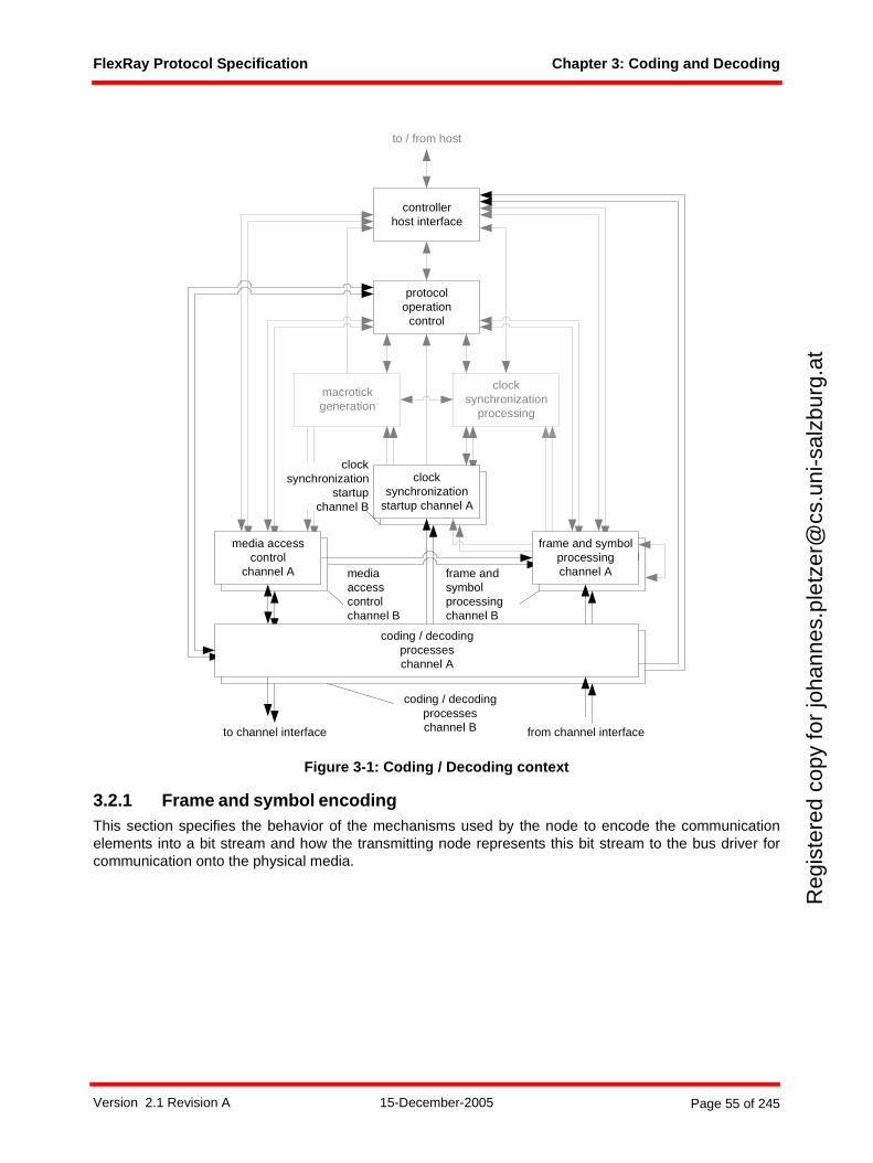
FlexRay Protocol Specification Chapter 3: Coding and Decoding
Reg
iste
red
copy
for
joha
nnes
.ple
tzer
@cs
.uni
-sal
zbur
g.at
Figure 3-1: Coding / Decoding context
3.2.1 Frame and symbol encodingThis section specifies the behavior of the mechanisms used by the node to encode the communicationelements into a bit stream and how the transmitting node represents this bit stream to the bus driver forcommunication onto the physical media.
frame and symbolprocessing
media accesscontrol
clocksynchronization
startup
macrotickgeneration
clocksynchronization
processing
protocoloperation
control
controllerhost interface
coding / decodingprocesseschannel A
frame and symbolprocessingchannel A
media accesscontrol
channel A
clocksynchronization
startup channel A
to channel interface from channel interface
to / from host
mediaaccesscontrolchannel B
coding / decodingprocesseschannel B
frame andsymbolprocessingchannel B
clocksynchronization
startupchannel B
Version 2.1 Revision A 15-December-2005 Page 55 of 245
FlexRay Protocol Specification Chapter 3: Coding and Decoding
Reg
iste
red
copy
for
joha
nnes
.ple
tzer
@cs
.uni
-sal
zbur
g.at
3.2.1.1 Frame encoding
3.2.1.1.1 Transmission start sequence
The transmission start sequence (TSS) is used to initiate proper connection setup through the network18.A transmitting node generates a TSS that consists of a continuous LOW for a period given by the parametergdTSSTransmitter.
3.2.1.1.2 Frame start sequence
The frame start sequence (FSS) is used to compensate for a possible quantization error in the first byte startsequence after the TSS. The FSS shall consist of one HIGH gdBit time. The node shall append an FSS tothe bit stream immediately following the TSS of a transmitted frame.
3.2.1.1.3 Byte start sequence
The byte start sequence (BSS) is used to provide bit stream timing information to the receiving devices. TheBSS shall consist of one HIGH gdBit time followed by one LOW gdBit time. Each byte of frame data shallbe sent on the channel as an extended byte sequence that consists of one BSS followed by eight data bits.
3.2.1.1.4 Frame end sequence
The frame end sequence (FES) is used to mark the end of the last byte sequence of a frame. The FES shallconsist of one LOW gdBit time followed by one HIGH gdBit time. The node shall append an FES to the bitstream immediately after the last extended byte sequence of the frame.
For frames transmitted in the static segment the second bit of the FES is the last bit in the transmitted bitstream. As a result, the transmitting node shall set the TxEN signal to HIGH at the end of the second bit ofthe FES.
For frames transmitted in the dynamic segment the FES is followed by the dynamic trailing sequence (seebelow).
3.2.1.1.5 Dynamic trailing sequence
The dynamic trailing sequence (DTS), which is only used for frames transmitted in the dynamic segment, isused to indicate the exact point in time of the transmitter's minislot action point19 and prevents prematurechannel idle detection20 by the receivers. When transmitting a frame in the dynamic segment the node shalltransmit a DTS immediately after the FES of the frame.
The DTS consists of two parts - a variable-length period with the TxD output at the LOW level, followed bya fixed-length period with the TxD output at the HIGH level. The minimum length of the LOW period is onegdBit. After this minimum length the node leaves the TxD output at the LOW level until the next minislotaction point. At the next minislot action point the node shall switch the TxD output to the HIGH level, andthe node shall switch the TxEN output to the HIGH level after a delay of 1 gdBit after the minislot actionpoint21. The duration of a DTS is variable and can assume any value between 2 gdBit (for a DTS composedof 1 gdBit LOW and 1 gdBit HIGH), and gdMinislot + 2 gdBit (if the DTS starts slightly later than one gdBitbefore a minislot action point).
Note that the processes defining the behavior of the CODEC do not have any direct knowledge of theminislot action point - those processes are informed of the appropriate time to end the generation of the DTSby the signal stop transmission on A sent by the MAC process.
18 The purpose of the TSS is to "open the gates" of an active star, i.e., to cause the star to properly set up input and output connections. During this set up, an active star truncates a number of bits at the beginning of a communication element. The TSS prevents the content of the frame or symbol from being truncated.
19 See also Chapter 5.20 See also section 3.2.4.21 This ensures that there is a period of one gdBit during which the TxD output is at the HIGH level prior to the transition of TxEN
output to the HIGH level. This is required for the stability of certain types of physical layers.
Version 2.1 Revision A 15-December-2005 Page 56 of 245
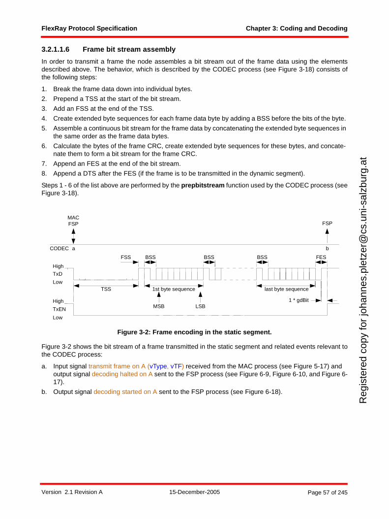
FlexRay Protocol Specification Chapter 3: Coding and Decoding
Reg
iste
red
copy
for
joha
nnes
.ple
tzer
@cs
.uni
-sal
zbur
g.at
3.2.1.1.6 Frame bit stream assembly
In order to transmit a frame the node assembles a bit stream out of the frame data using the elementsdescribed above. The behavior, which is described by the CODEC process (see Figure 3-18) consists ofthe following steps:
1. Break the frame data down into individual bytes.
2. Prepend a TSS at the start of the bit stream.
3. Add an FSS at the end of the TSS.
4. Create extended byte sequences for each frame data byte by adding a BSS before the bits of the byte.
5. Assemble a continuous bit stream for the frame data by concatenating the extended byte sequences in the same order as the frame data bytes.
6. Calculate the bytes of the frame CRC, create extended byte sequences for these bytes, and concate-nate them to form a bit stream for the frame CRC.
7. Append an FES at the end of the bit stream.
8. Append a DTS after the FES (if the frame is to be transmitted in the dynamic segment).
Steps 1 - 6 of the list above are performed by the prepbitstream function used by the CODEC process (seeFigure 3-18).
Figure 3-2: Frame encoding in the static segment.
Figure 3-2 shows the bit stream of a frame transmitted in the static segment and related events relevant tothe CODEC process:
a. Input signal transmit frame on A (vType, vTF) received from the MAC process (see Figure 5-17) and output signal decoding halted on A sent to the FSP process (see Figure 6-9, Figure 6-10, and Figure 6-17).
b. Output signal decoding started on A sent to the FSP process (see Figure 6-18).
FSS
TSS
High
Low
TxD
1st byte sequence last byte sequence
High
Low
TxEN MSB LSB
BSS
1 * gdBit
a b
BSS FES
MACFSP
CODEC
FSP
BSS
Version 2.1 Revision A 15-December-2005 Page 57 of 245
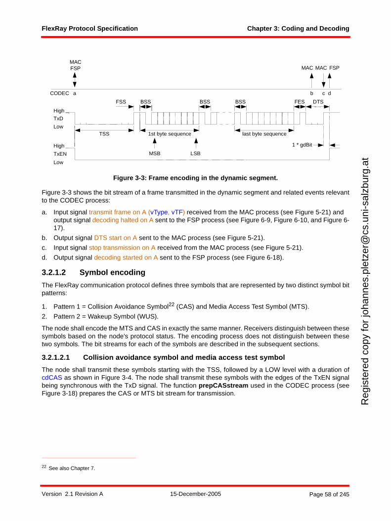
FlexRay Protocol Specification Chapter 3: Coding and Decoding
Reg
iste
red
copy
for
joha
nnes
.ple
tzer
@cs
.uni
-sal
zbur
g.at
Figure 3-3: Frame encoding in the dynamic segment.
Figure 3-3 shows the bit stream of a frame transmitted in the dynamic segment and related events relevantto the CODEC process:
a. Input signal transmit frame on A (vType, vTF) received from the MAC process (see Figure 5-21) and output signal decoding halted on A sent to the FSP process (see Figure 6-9, Figure 6-10, and Figure 6-17).
b. Output signal DTS start on A sent to the MAC process (see Figure 5-21).
c. Input signal stop transmission on A received from the MAC process (see Figure 5-21).
d. Output signal decoding started on A sent to the FSP process (see Figure 6-18).
3.2.1.2 Symbol encoding
The FlexRay communication protocol defines three symbols that are represented by two distinct symbol bitpatterns:
1. Pattern 1 = Collision Avoidance Symbol22 (CAS) and Media Access Test Symbol (MTS).
2. Pattern 2 = Wakeup Symbol (WUS).
The node shall encode the MTS and CAS in exactly the same manner. Receivers distinguish between thesesymbols based on the node's protocol status. The encoding process does not distinguish between thesetwo symbols. The bit streams for each of the symbols are described in the subsequent sections.
3.2.1.2.1 Collision avoidance symbol and media access test symbol
The node shall transmit these symbols starting with the TSS, followed by a LOW level with a duration ofcdCAS as shown in Figure 3-4. The node shall transmit these symbols with the edges of the TxEN signalbeing synchronous with the TxD signal. The function prepCASstream used in the CODEC process (seeFigure 3-18) prepares the CAS or MTS bit stream for transmission.
22 See also Chapter 7.
FSS
TSS
High
Low
TxD
1st byte sequence
FES
last byte sequence
High
Low
TxEN MSB LSB
1 * gdBit
DTS
a db
BSSBSS
FSP
CODEC c
MAC MACMACFSP
BSS
Version 2.1 Revision A 15-December-2005 Page 58 of 245
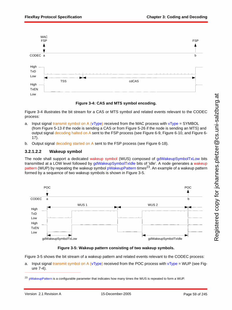
FlexRay Protocol Specification Chapter 3: Coding and Decoding
Reg
iste
red
copy
for
joha
nnes
.ple
tzer
@cs
.uni
-sal
zbur
g.at
Figure 3-4: CAS and MTS symbol encoding.
Figure 3-4 illustrates the bit stream for a CAS or MTS symbol and related events relevant to the CODECprocess:
a. Input signal transmit symbol on A (vType) received from the MAC process with vType = SYMBOL (from Figure 5-13 if the node is sending a CAS or from Figure 5-26 if the node is sending an MTS) and output signal decoding halted on A sent to the FSP process (see Figure 6-9, Figure 6-10, and Figure 6-17).
b. Output signal decoding started on A sent to the FSP process (see Figure 6-18).
3.2.1.2.2 Wakeup symbol
The node shall support a dedicated wakeup symbol (WUS) composed of gdWakeupSymbolTxLow bitstransmitted at a LOW level followed by gdWakeupSymbolTxIdle bits of 'idle'. A node generates a wakeuppattern (WUP) by repeating the wakeup symbol pWakeupPattern times23. An example of a wakeup patternformed by a sequence of two wakeup symbols is shown in Figure 3-5.
Figure 3-5: Wakeup pattern consisting of two wakeup symbols.
Figure 3-5 shows the bit stream of a wakeup pattern and related events relevant to the CODEC process:
a. Input signal transmit symbol on A (vType) received from the POC process with vType = WUP (see Fig-ure 7-4).
23 pWakeupPattern is a configurable parameter that indicates how many times the WUS is repeated to form a WUP.
cdCAS
High
Low
TxD
High
Low
TxEN
TSS
a bCODEC
MACFSP FSP
WUS 1 WUS 2
gdWakeupSymbolTxLow
High
LowTxD
High
LowTxEN
a b
POC
CODEC
POC
gdWakeupSymbolTxIdle
Version 2.1 Revision A 15-December-2005 Page 59 of 245
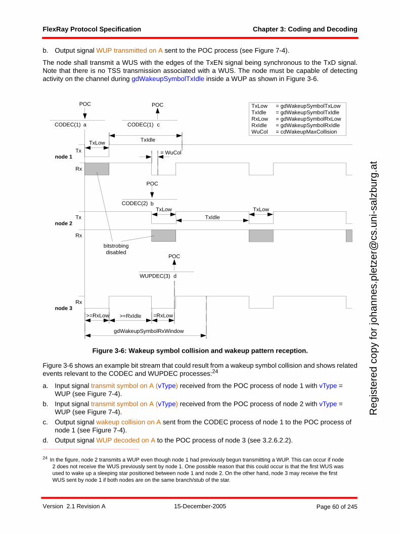
FlexRay Protocol Specification Chapter 3: Coding and Decoding
Reg
iste
red
copy
for
joha
nnes
.ple
tzer
@cs
.uni
-sal
zbur
g.at
b. Output signal WUP transmitted on A sent to the POC process (see Figure 7-4).
The node shall transmit a WUS with the edges of the TxEN signal being synchronous to the TxD signal.Note that there is no TSS transmission associated with a WUS. The node must be capable of detectingactivity on the channel during gdWakeupSymbolTxIdle inside a WUP as shown in Figure 3-6.
Figure 3-6: Wakeup symbol collision and wakeup pattern reception.
Figure 3-6 shows an example bit stream that could result from a wakeup symbol collision and shows relatedevents relevant to the CODEC and WUPDEC processes:24
a. Input signal transmit symbol on A (vType) received from the POC process of node 1 with vType = WUP (see Figure 7-4).
b. Input signal transmit symbol on A (vType) received from the POC process of node 2 with vType = WUP (see Figure 7-4).
c. Output signal wakeup collision on A sent from the CODEC process of node 1 to the POC process of node 1 (see Figure 7-4).
d. Output signal WUP decoded on A to the POC process of node 3 (see 3.2.6.2.2).
24 In the figure, node 2 transmits a WUP even though node 1 had previously begun transmitting a WUP. This can occur if node 2 does not receive the WUS previously sent by node 1. One possible reason that this could occur is that the first WUS was used to wake up a sleeping star positioned between node 1 and node 2. On the other hand, node 3 may receive the first WUS sent by node 1 if both nodes are on the same branch/stub of the star.
TxLow = gdWakeupSymbolTxLowTxIdle = gdWakeupSymbolTxIdleRxLow = gdWakeupSymbolRxLowRxIdle = gdWakeupSymbolRxIdleWuCol = cdWakeupMaxCollision
Tx
d
POC
= WuCol
WUPDEC(3)
TxIdle
TxLow
TxLow
>=RxLow =RxLow>=RxIdle
Tx
Rx
node 1
node 2
Rx
Rxnode 3
c
POC
CODEC(1)a
POC
CODEC(1)
b
POC
CODEC(2)
gdWakeupSymbolRxWindow
bitstrobingdisabled
TxLow
TxIdle
Version 2.1 Revision A 15-December-2005 Page 60 of 245
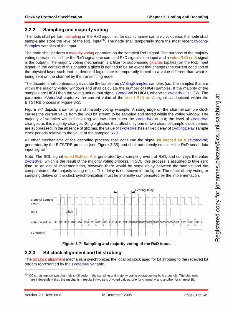
FlexRay Protocol Specification Chapter 3: Coding and Decoding
Reg
iste
red
copy
for
joha
nnes
.ple
tzer
@cs
.uni
-sal
zbur
g.at
3.2.2 Sampling and majority votingThe node shall perform sampling on the RxD input, i.e., for each channel sample clock period the node shallsample and store the level of the RxD input25. The node shall temporarily store the most recent cVoting-Samples samples of the input.
The node shall perform a majority voting operation on the sampled RxD signal. The purpose of the majorityvoting operation is to filter the RxD signal (the sampled RxD signal is the input and a voted RxD on A signalis the output). The majority voting mechanism is a filter for suppressing glitches (spikes) on the RxD inputsignal. In the context of this chapter a glitch is defined to be an event that changes the current condition ofthe physical layer such that its detected logic state is temporarily forced to a value different than what isbeing sent on the channel by the transmitting node.
The decoder shall continuously evaluate the last stored cVotingSamples samples (i.e., the samples that arewithin the majority voting window) and shall calculate the number of HIGH samples. If the majority of thesamples are HIGH then the voting unit output signal zVotedVal is HIGH, otherwise zVotedVal is LOW. Theparameter zVotedVal captures the current value of the voted RxD on A signal as depicted within theBITSTRB process in Figure 3-35.
Figure 3-7 depicts a sampling and majority voting example. A rising edge on the channel sample clockcauses the current value from the RxD bit stream to be sampled and stored within the voting window. Themajority of samples within the voting window determines the zVotedVal output; the level of zVotedValchanges as this majority changes. Single glitches that affect only one or two channel sample clock periodsare suppressed. In the absence of glitches, the value of zVotedVal has a fixed delay of cVotingDelay sampleclock periods relative to the value of the sampled RxD.
All other mechanisms of the decoding process shall consume the signal bit strobed on A (zVotedVal)generated by the BITSTRB process (see Figure 3-35) and shall not directly consider the RxD serial datainput signal.
Note: The SDL signal voted RxD on A is generated by a sampling event of RxD, and conveys the valuezVotedVal, which is the result of the majority voting process. In SDL, this process is assumed to take zerotime. In an actual implementation, however, there would be some delay between the sample and thecomputation of the majority voting result. This delay is not shown in the figure. The effect of any voting orsampling delays on the clock synchronization must be internally compensated by the implementation.
Figure 3-7: Sampling and majority voting of the RxD input.
3.2.3 Bit clock alignment and bit strobingThe bit clock alignment mechanism synchronizes the local bit clock used for bit strobing to the received bitstream represented by the zVotedVal variable.
25 CC's that support two channels shall perform the sampling and majority voting operations for both channels. The channels are independent (i.e., the mechanism results in two sets of voted values, one for channel A and another for channel B).
channel sampleclock
RxD
voting window
zVotedVal
11111 11111 11110 11100 1100110011 00111 11111 11110 11100 11000 10000 0000001111 00000 00000 00000 00001 00011 00111 01111
glitch
cVotingDelay
Version 2.1 Revision A 15-December-2005 Page 61 of 245
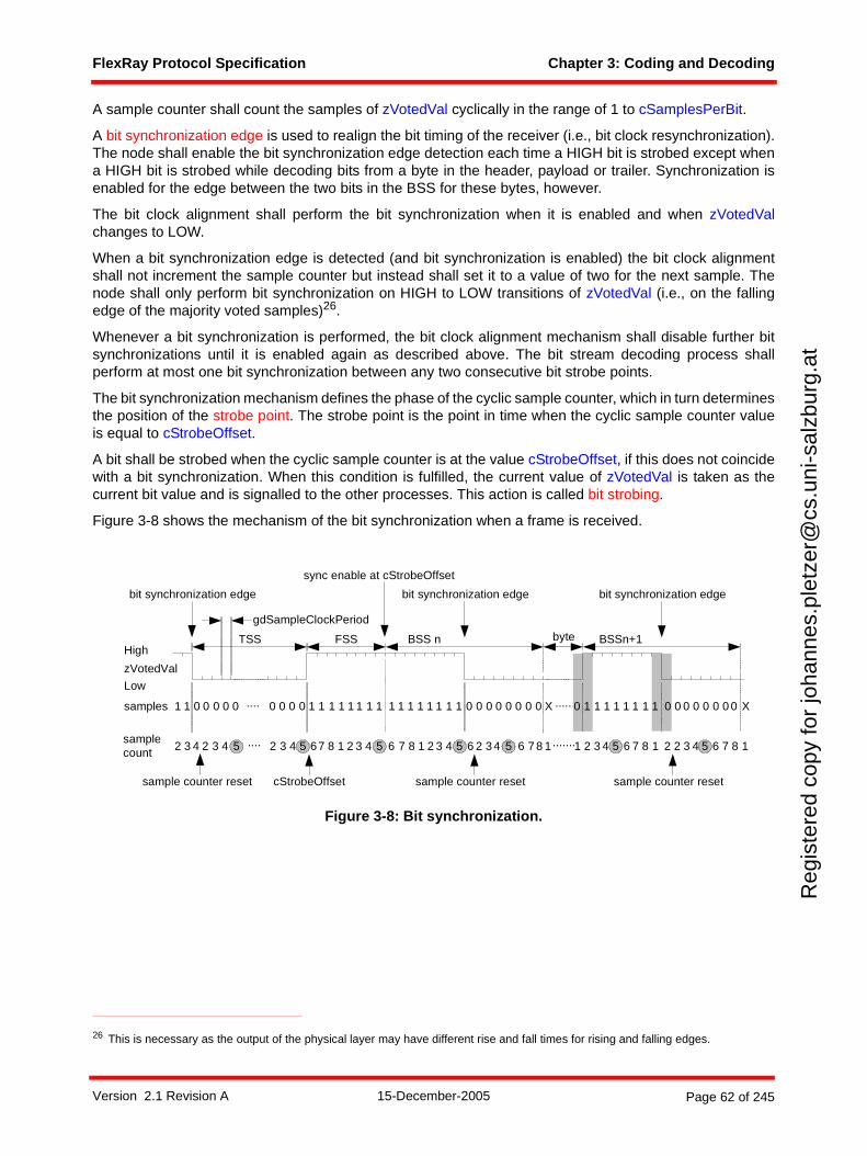
FlexRay Protocol Specification Chapter 3: Coding and Decoding
Reg
iste
red
copy
for
joha
nnes
.ple
tzer
@cs
.uni
-sal
zbur
g.at
A sample counter shall count the samples of zVotedVal cyclically in the range of 1 to cSamplesPerBit.
A bit synchronization edge is used to realign the bit timing of the receiver (i.e., bit clock resynchronization).The node shall enable the bit synchronization edge detection each time a HIGH bit is strobed except whena HIGH bit is strobed while decoding bits from a byte in the header, payload or trailer. Synchronization isenabled for the edge between the two bits in the BSS for these bytes, however.
The bit clock alignment shall perform the bit synchronization when it is enabled and when zVotedValchanges to LOW.
When a bit synchronization edge is detected (and bit synchronization is enabled) the bit clock alignmentshall not increment the sample counter but instead shall set it to a value of two for the next sample. Thenode shall only perform bit synchronization on HIGH to LOW transitions of zVotedVal (i.e., on the fallingedge of the majority voted samples)26.
Whenever a bit synchronization is performed, the bit clock alignment mechanism shall disable further bitsynchronizations until it is enabled again as described above. The bit stream decoding process shallperform at most one bit synchronization between any two consecutive bit strobe points.
The bit synchronization mechanism defines the phase of the cyclic sample counter, which in turn determinesthe position of the strobe point. The strobe point is the point in time when the cyclic sample counter valueis equal to cStrobeOffset.
A bit shall be strobed when the cyclic sample counter is at the value cStrobeOffset, if this does not coincidewith a bit synchronization. When this condition is fulfilled, the current value of zVotedVal is taken as thecurrent bit value and is signalled to the other processes. This action is called bit strobing.
Figure 3-8 shows the mechanism of the bit synchronization when a frame is received.
Figure 3-8: Bit synchronization.
26 This is necessary as the output of the physical layer may have different rise and fall times for rising and falling edges.
High
Low
zVotedVal
TSS FSS byteBSS n
samples 1 0 0 0 0 0 .... 0 0 0 0
cStrobeOffset
1 1 1 1 1 1 1 1 1 1 1 1 0 0 0 0 0 .....0 0 0
gdSampleClockPeriod
samplecount
1
3 4 2 3 4 .... 2 3 4 67 8 1 62
1
2
1 1 1
3 4 7 8 1 2 3 4 6 62 34 7 8 1
bit synchronization edge
sample counter reset
X 0
BSSn+1
1 1 1 1 1 1 1 1 0 0 0 0 00 0 0
4 6 7 8 12 3 4 16 7 8 2 2 3
X
1
sync enable at cStrobeOffset
bit synchronization edgebit synchronization edge
5 5 5 5 55 5.......
sample counter resetsample counter reset
Version 2.1 Revision A 15-December-2005 Page 62 of 245
FlexRay Protocol Specification Chapter 3: Coding and Decoding
Reg
iste
red
copy
for
joha
nnes
.ple
tzer
@cs
.uni
-sal
zbur
g.at
The example from Figure 3-8 shows the nominal case of an FSS and BSS with cSamplesPerBit samples.At the bit synchronization edge, the sample counter is set to '2' for the sample following the detected edge.The example also shows a misalignment after the received first header byte of the frame. The misalignmentis reflected by the value of the sample counter at the start of the HIGH bit of the BSS (see the first highlightedarea). The first expected sample (HIGH) of BSS n + 1 should occur when the sample counter value is '1'.Since it actually occurs when the sample counter value is '2', the edge was decoded with a delay of onechannel sample clock period. Bit synchronization, performed by resetting the sample counter, takes placewith the next bit synchronization edge (see second highlighted area). The effect of the bit synchronizationis that the distance of edge to the strobe point is the same as if the edge would have appeared at theexpected sample (see also 3.2.7).
To detect activity on a channel, it is necessary that at least cStrobeOffset consecutive LOW samples makeit through the majority voter27. This is a consequence of the combination of the majority voting and the bitsynchronization mechanisms.
The SDL representation of the BITSTRB process is depicted in Figure 3-35.
3.2.4 Channel idle detectionThe node shall use a channel idle detection mechanism to identify the end of the current communicationelement. The channel idle detection is context insensitive, i.e., channel idle is detected whenever cChannel-IdleDelimiter consecutive strobed HIGH bits are decoded on a channel that is not currently considered tobe idle. However, idle detection is not active while the node is encoding a communication element. Thedecoding and encoding mechanisms are mutually exclusive and idle detection is a logical component of thedecoding mechanism.
When the CODEC process is created by the POC, it immediately creates the BITSTRB process and puts itin the GO mode where idle detection is performed. The initial assumption is that the channel is active, socChannelIdleDelimiter consecutive strobed HIGH bits must be decoded to detect that the channel is actuallyidle (section 3.4.2).
The BITSTRB process is toggled between the GO and STANDBY modes by the CODEC process. Whenthe CODEC process is encoding a communication element, the BITSTRB process is placed in theSTANDBY mode and idle detection is terminated. When the encoding of a communication element isconcluded, the CODEC places the BITSTRB process in the GO mode where idle detection is reactivated.Whenever the BITSTRB process is placed in the GO mode, the initial assumption of the BITSTRB processis that the channel is active, so cChannelIdleDelimiter consecutive strobed HIGH bits must be subsequentlydecoded to detect that the channel is actually idle.
3.2.5 Action point and time reference pointAs defined in Chapter 5, an action point (AP) is an instant in time at which a node performs a specific actionin alignment with its local time base, e.g. when a transmitter starts the transmission of a frame.
The clock synchronization algorithm requires a measurement of the time difference between the static slotaction point of the transmitter of a sync frame and the static slot action point of the corresponding slot in thereceiving node. Obviously, a receiving node does not have direct knowledge of the static slot action pointof a different node. The clock synchronization algorithm instead infers the time of the transmitter's actionpoint by making a measurement of the arrival time of a received sync frame28.
27 In order to allow the detection of colliding startup frames, a FlexRay system must be configured in such a way that in the event of colliding startup frames a node shall detect at least one strobed LOW bit so that detectable noise is produced to enable setting of the tWakeupNoise timer (see Chapter 7).
28 This is possible because transmission of the sync frame begins at the static slot action point of the transmitting node.
Version 2.1 Revision A 15-December-2005 Page 63 of 245
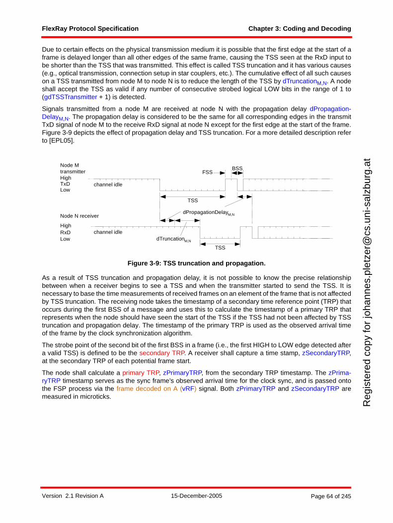
FlexRay Protocol Specification Chapter 3: Coding and Decoding
Reg
iste
red
copy
for
joha
nnes
.ple
tzer
@cs
.uni
-sal
zbur
g.at
Due to certain effects on the physical transmission medium it is possible that the first edge at the start of aframe is delayed longer than all other edges of the same frame, causing the TSS seen at the RxD input tobe shorter than the TSS that was transmitted. This effect is called TSS truncation and it has various causes(e.g., optical transmission, connection setup in star couplers, etc.). The cumulative effect of all such causeson a TSS transmitted from node M to node N is to reduce the length of the TSS by dTruncationM,N. A nodeshall accept the TSS as valid if any number of consecutive strobed logical LOW bits in the range of 1 to(gdTSSTransmitter + 1) is detected.
Signals transmitted from a node M are received at node N with the propagation delay dPropagation-DelayM,N. The propagation delay is considered to be the same for all corresponding edges in the transmitTxD signal of node M to the receive RxD signal at node N except for the first edge at the start of the frame.Figure 3-9 depicts the effect of propagation delay and TSS truncation. For a more detailed description referto [EPL05].
Figure 3-9: TSS truncation and propagation.
As a result of TSS truncation and propagation delay, it is not possible to know the precise relationshipbetween when a receiver begins to see a TSS and when the transmitter started to send the TSS. It isnecessary to base the time measurements of received frames on an element of the frame that is not affectedby TSS truncation. The receiving node takes the timestamp of a secondary time reference point (TRP) thatoccurs during the first BSS of a message and uses this to calculate the timestamp of a primary TRP thatrepresents when the node should have seen the start of the TSS if the TSS had not been affected by TSStruncation and propagation delay. The timestamp of the primary TRP is used as the observed arrival timeof the frame by the clock synchronization algorithm.
The strobe point of the second bit of the first BSS in a frame (i.e., the first HIGH to LOW edge detected aftera valid TSS) is defined to be the secondary TRP. A receiver shall capture a time stamp, zSecondaryTRP,at the secondary TRP of each potential frame start.
The node shall calculate a primary TRP, zPrimaryTRP, from the secondary TRP timestamp. The zPrima-ryTRP timestamp serves as the sync frame's observed arrival time for the clock sync, and is passed ontothe FSP process via the frame decoded on A (vRF) signal. Both zPrimaryTRP and zSecondaryTRP aremeasured in microticks.
Node MtransmitterHigh
LowTxD channel idle
Node N receiver
High
LowRxD channel idle
dTruncationM,N
dPropagationDelayM,N
BSS
TSS
TSS
FSS
Version 2.1 Revision A 15-December-2005 Page 64 of 245
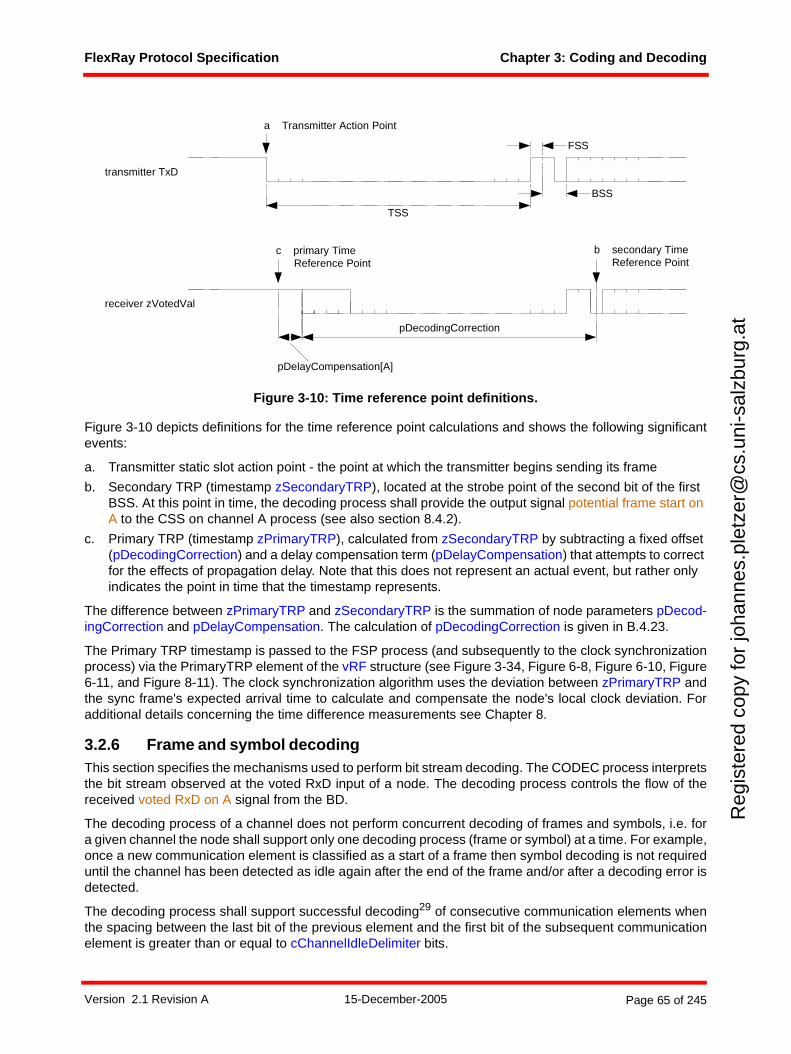
FlexRay Protocol Specification Chapter 3: Coding and Decoding
Reg
iste
red
copy
for
joha
nnes
.ple
tzer
@cs
.uni
-sal
zbur
g.at
Figure 3-10: Time reference point definitions.
Figure 3-10 depicts definitions for the time reference point calculations and shows the following significantevents:
a. Transmitter static slot action point - the point at which the transmitter begins sending its frame
b. Secondary TRP (timestamp zSecondaryTRP), located at the strobe point of the second bit of the first BSS. At this point in time, the decoding process shall provide the output signal potential frame start on A to the CSS on channel A process (see also section 8.4.2).
c. Primary TRP (timestamp zPrimaryTRP), calculated from zSecondaryTRP by subtracting a fixed offset (pDecodingCorrection) and a delay compensation term (pDelayCompensation) that attempts to correct for the effects of propagation delay. Note that this does not represent an actual event, but rather only indicates the point in time that the timestamp represents.
The difference between zPrimaryTRP and zSecondaryTRP is the summation of node parameters pDecod-ingCorrection and pDelayCompensation. The calculation of pDecodingCorrection is given in B.4.23.
The Primary TRP timestamp is passed to the FSP process (and subsequently to the clock synchronizationprocess) via the PrimaryTRP element of the vRF structure (see Figure 3-34, Figure 6-8, Figure 6-10, Figure6-11, and Figure 8-11). The clock synchronization algorithm uses the deviation between zPrimaryTRP andthe sync frame's expected arrival time to calculate and compensate the node's local clock deviation. Foradditional details concerning the time difference measurements see Chapter 8.
3.2.6 Frame and symbol decodingThis section specifies the mechanisms used to perform bit stream decoding. The CODEC process interpretsthe bit stream observed at the voted RxD input of a node. The decoding process controls the flow of thereceived voted RxD on A signal from the BD.
The decoding process of a channel does not perform concurrent decoding of frames and symbols, i.e. fora given channel the node shall support only one decoding process (frame or symbol) at a time. For example,once a new communication element is classified as a start of a frame then symbol decoding is not requireduntil the channel has been detected as idle again after the end of the frame and/or after a decoding error isdetected.
The decoding process shall support successful decoding29 of consecutive communication elements whenthe spacing between the last bit of the previous element and the first bit of the subsequent communicationelement is greater than or equal to cChannelIdleDelimiter bits.
pDecodingCorrection
TSS
a Transmitter Action Point
transmitter TxD
receiver zVotedVal
FSS
BSS
pDelayCompensation[A]
b secondary Time Reference Point
c primary Time Reference Point
Version 2.1 Revision A 15-December-2005 Page 65 of 245
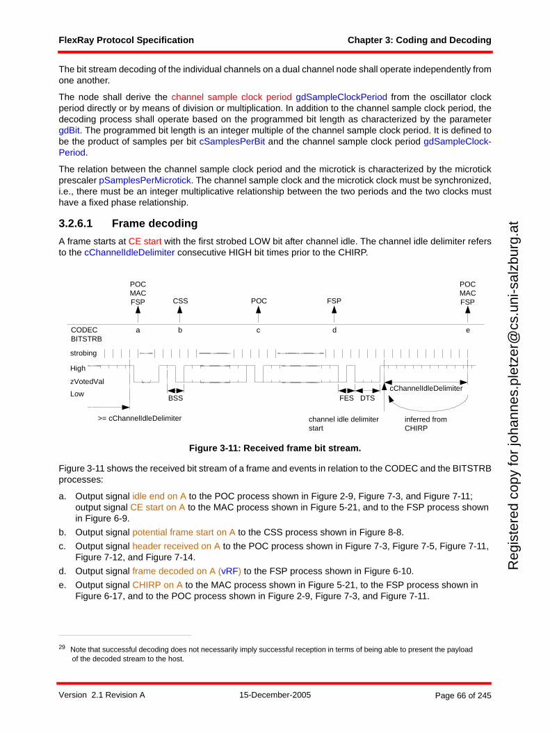
FlexRay Protocol Specification Chapter 3: Coding and Decoding
Reg
iste
red
copy
for
joha
nnes
.ple
tzer
@cs
.uni
-sal
zbur
g.at
The bit stream decoding of the individual channels on a dual channel node shall operate independently fromone another.
The node shall derive the channel sample clock period gdSampleClockPeriod from the oscillator clockperiod directly or by means of division or multiplication. In addition to the channel sample clock period, thedecoding process shall operate based on the programmed bit length as characterized by the parametergdBit. The programmed bit length is an integer multiple of the channel sample clock period. It is defined tobe the product of samples per bit cSamplesPerBit and the channel sample clock period gdSampleClock-Period.
The relation between the channel sample clock period and the microtick is characterized by the microtickprescaler pSamplesPerMicrotick. The channel sample clock and the microtick clock must be synchronized,i.e., there must be an integer multiplicative relationship between the two periods and the two clocks musthave a fixed phase relationship.
3.2.6.1 Frame decoding
A frame starts at CE start with the first strobed LOW bit after channel idle. The channel idle delimiter refersto the cChannelIdleDelimiter consecutive HIGH bit times prior to the CHIRP.
Figure 3-11: Received frame bit stream.
Figure 3-11 shows the received bit stream of a frame and events in relation to the CODEC and the BITSTRBprocesses:
a. Output signal idle end on A to the POC process shown in Figure 2-9, Figure 7-3, and Figure 7-11; output signal CE start on A to the MAC process shown in Figure 5-21, and to the FSP process shown in Figure 6-9.
b. Output signal potential frame start on A to the CSS process shown in Figure 8-8.
c. Output signal header received on A to the POC process shown in Figure 7-3, Figure 7-5, Figure 7-11, Figure 7-12, and Figure 7-14.
d. Output signal frame decoded on A (vRF) to the FSP process shown in Figure 6-10.
e. Output signal CHIRP on A to the MAC process shown in Figure 5-21, to the FSP process shown in Figure 6-17, and to the POC process shown in Figure 2-9, Figure 7-3, and Figure 7-11.
29 Note that successful decoding does not necessarily imply successful reception in terms of being able to present the payload of the decoded stream to the host.
channel idle delimiterstart
a
strobing
cChannelIdleDelimiter
High
Low
zVotedVal
inferred fromCHIRP
b c d
DTS
>= cChannelIdleDelimiter
CODECBITSTRB
e
FESBSS
FSPCSS POC
POCMACFSP
POCMACFSP
Version 2.1 Revision A 15-December-2005 Page 66 of 245
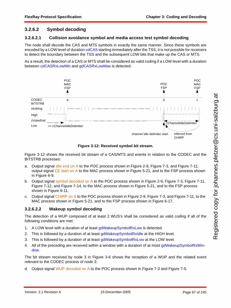
FlexRay Protocol Specification Chapter 3: Coding and Decoding
Reg
iste
red
copy
for
joha
nnes
.ple
tzer
@cs
.uni
-sal
zbur
g.at
3.2.6.2 Symbol decoding
3.2.6.2.1 Collision avoidance symbol and media access test symbol decoding
The node shall decode the CAS and MTS symbols in exactly the same manner. Since these symbols areencoded by a LOW level of duration cdCAS starting immediately after the TSS, it is not possible for receiversto detect the boundary between the TSS and the subsequent LOW bits that make up the CAS or MTS.
As a result, the detection of a CAS or MTS shall be considered as valid coding if a LOW level with a durationbetween cdCASRxLowMin and gdCASRxLowMax is detected.
Figure 3-12: Received symbol bit stream.
Figure 3-12 shows the received bit stream of a CAS/MTS and events in relation to the CODEC and theBITSTRB processes:
a. Output signal idle end on A to the POC process shown in Figure 2-9, Figure 7-3, and Figure 7-11; output signal CE start on A to the MAC process shown in Figure 5-21, and to the FSP process shown in Figure 6-9.
b. Output signal symbol decoded on A to the POC process shown in Figure 2-9, Figure 7-3, Figure 7-11, Figure 7-12, and Figure 7-14, to the MAC process shown in Figure 5-21, and to the FSP process shown in Figure 6-11.
c. Output signal CHIRP on A to the POC process shown in Figure 2-9, Figure 7-3, and Figure 7-11, to the MAC process shown in Figure 5-21, and to the FSP process shown in Figure 6-17.
3.2.6.2.2 Wakeup symbol decoding
The detection of a WUP composed of at least 2 WUS's shall be considered as valid coding if all of thefollowing conditions are met:
1. A LOW level with a duration of at least gdWakeupSymbolRxLow is detected.
2. This is followed by a duration of at least gdWakeupSymbolRxIdle at the HIGH level.
3. This is followed by a duration of at least gdWakeupSymbolRxLow at the LOW level.
4. All of the preceding are received within a window with a duration of at most gdWakeupSymbolRxWin-dow.
The bit stream received by node 3 in Figure 3-6 shows the reception of a WUP and the related eventrelevant to the CODEC process of node 3:
d. Output signal WUP decoded on A to the POC process shown in Figure 7-3 and Figure 7-5.
strobing
High
Low
zVotedValcChannelIdleDelimiter
channel idle delimiter start
>= cChannelIdleDelimiter
a bCODECBITSTRB
inferred fromCHIRP
POCMACFSP
c
POCMACFSP
POCFSP
Version 2.1 Revision A 15-December-2005 Page 67 of 245
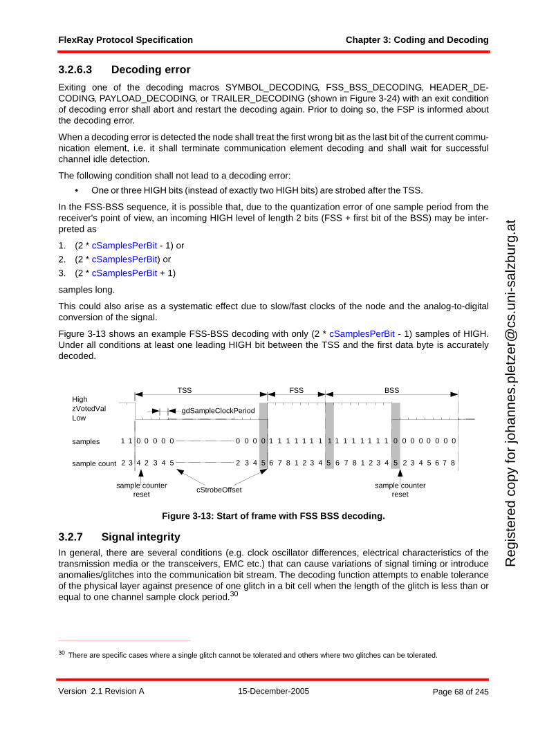
FlexRay Protocol Specification Chapter 3: Coding and Decoding
Reg
iste
red
copy
for
joha
nnes
.ple
tzer
@cs
.uni
-sal
zbur
g.at
3.2.6.3 Decoding error
Exiting one of the decoding macros SYMBOL_DECODING, FSS_BSS_DECODING, HEADER_DE-CODING, PAYLOAD_DECODING, or TRAILER_DECODING (shown in Figure 3-24) with an exit conditionof decoding error shall abort and restart the decoding again. Prior to doing so, the FSP is informed aboutthe decoding error.
When a decoding error is detected the node shall treat the first wrong bit as the last bit of the current commu-nication element, i.e. it shall terminate communication element decoding and shall wait for successfulchannel idle detection.
The following condition shall not lead to a decoding error:
• One or three HIGH bits (instead of exactly two HIGH bits) are strobed after the TSS.
In the FSS-BSS sequence, it is possible that, due to the quantization error of one sample period from thereceiver's point of view, an incoming HIGH level of length 2 bits (FSS + first bit of the BSS) may be inter-preted as
1. (2 * cSamplesPerBit - 1) or
2. (2 * cSamplesPerBit) or
3. (2 * cSamplesPerBit + 1)
samples long.
This could also arise as a systematic effect due to slow/fast clocks of the node and the analog-to-digitalconversion of the signal.
Figure 3-13 shows an example FSS-BSS decoding with only (2 * cSamplesPerBit - 1) samples of HIGH.Under all conditions at least one leading HIGH bit between the TSS and the first data byte is accuratelydecoded.
Figure 3-13: Start of frame with FSS BSS decoding.
3.2.7 Signal integrityIn general, there are several conditions (e.g. clock oscillator differences, electrical characteristics of thetransmission media or the transceivers, EMC etc.) that can cause variations of signal timing or introduceanomalies/glitches into the communication bit stream. The decoding function attempts to enable toleranceof the physical layer against presence of one glitch in a bit cell when the length of the glitch is less than orequal to one channel sample clock period.30
30 There are specific cases where a single glitch cannot be tolerated and others where two glitches can be tolerated.
High
LowzVotedVal
TSS FSS
samples 1 0 0 0 0 0 0 0 0 0 1 1 1 1
gdSampleClockPeriod
sample count
1
3 4 2 3 4 5 2 3 4 5 6 7 8 1 2
1
2
1 1 1
3 4 5
sample counterreset
1 1 1
BSS
1 1 1 1 0 0 0 0 0 0 0 0
6 7 8 1 2 3 4 5 2 3 4 5 6 7 8
cStrobeOffsetsample counter
reset
Version 2.1 Revision A 15-December-2005 Page 68 of 245
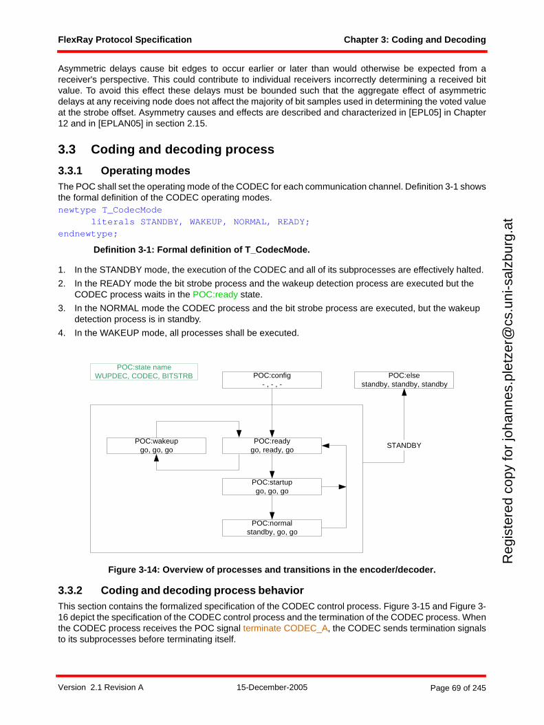
FlexRay Protocol Specification Chapter 3: Coding and Decoding
Reg
iste
red
copy
for
joha
nnes
.ple
tzer
@cs
.uni
-sal
zbur
g.at
Asymmetric delays cause bit edges to occur earlier or later than would otherwise be expected from areceiver's perspective. This could contribute to individual receivers incorrectly determining a received bitvalue. To avoid this effect these delays must be bounded such that the aggregate effect of asymmetricdelays at any receiving node does not affect the majority of bit samples used in determining the voted valueat the strobe offset. Asymmetry causes and effects are described and characterized in [EPL05] in Chapter12 and in [EPLAN05] in section 2.15.
3.3 Coding and decoding process
3.3.1 Operating modesThe POC shall set the operating mode of the CODEC for each communication channel. Definition 3-1 showsthe formal definition of the CODEC operating modes.newtype T_CodecMode
literals STANDBY, WAKEUP, NORMAL, READY;endnewtype;
Definition 3-1: Formal definition of T_CodecMode.
1. In the STANDBY mode, the execution of the CODEC and all of its subprocesses are effectively halted.
2. In the READY mode the bit strobe process and the wakeup detection process are executed but the CODEC process waits in the POC:ready state.
3. In the NORMAL mode the CODEC process and the bit strobe process are executed, but the wakeup detection process is in standby.
4. In the WAKEUP mode, all processes shall be executed.
Figure 3-14: Overview of processes and transitions in the encoder/decoder.
3.3.2 Coding and decoding process behaviorThis section contains the formalized specification of the CODEC control process. Figure 3-15 and Figure 3-16 depict the specification of the CODEC control process and the termination of the CODEC process. Whenthe CODEC process receives the POC signal terminate CODEC_A, the CODEC sends termination signalsto its subprocesses before terminating itself.
POC:state nameWUPDEC, CODEC, BITSTRB POC:config
- , - , -
POC:readygo, ready, go
POC:wakeupgo, go, go
POC:normalstandby, go, go
POC:elsestandby, standby, standby
STANDBY
POC:startupgo, go, go
Version 2.1 Revision A 15-December-2005 Page 69 of 245
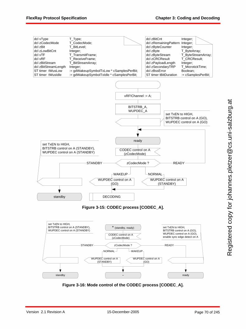
FlexRay Protocol Specification Chapter 3: Coding and Decoding
Reg
iste
red
copy
for
joha
nnes
.ple
tzer
@cs
.uni
-sal
zbur
g.at
Figure 3-15: CODEC process [CODEC_A].
Figure 3-16: Mode control of the CODEC process [CODEC_A].
CODEC control on A(zCodecMode)
zCodecMode ?
WAKEUP
ready
NORMAL
WUPDEC control on A(GO)
dcl vType T_Type;dcl zCodecMode T_CodecMode;dcl zBit T_BitLevel;dcl zLowBitCnt Integer;dcl vTF T_TransmitFrame;dcl vRF T_ReceiveFrame;dcl zBitStream T_BitStreamArray;dcl zBitStreamLength Integer;ST timer tWusLow := gdWakeupSymbolTxLow * cSamplesPerBit;ST timer tWusIdle := gdWakeupSymbolTxIdle * cSamplesPerBit;
dcl zBitCnt Integer;dcl zRemainingPattern Integer;dcl zByteCounter Integer;dcl zByte T_ByteArray;dcl zByteStream T_ByteStreamArray;dcl zCRCResult T_CRCResult;dcl zPayloadLength Integer;dcl zSecondaryTRP T_MicrotickTime;dcl zBssError Boolean;ST timer tBitDuration := cSamplesPerBit;
set TxEN to HIGH,BITSTRB control on A (GO),WUPDEC control on A (GO)
WUPDEC control on A(STANDBY)
DECODING
STANDBY
standby
set TxEN to HIGH,BITSTRB control on A (STANDBY),WUPDEC control on A (STANDBY)
vRF!Channel := A;
READY
BITSTRB_A,WUPDEC_A
STANDBY
set TxEN to HIGH,BITSTRB control on A (STANDBY),WUPDEC control on A (STANDBY)
standby ready
CODEC control on A(zCodecMode)
* (standby, ready)
zCodecMode ? READY
-
NORMAL
WUPDEC control on A(STANDBY)
WUPDEC control on A(GO)
set TxEN to HIGH,BITSTRB control on A (GO),WUPDEC control on A (GO),enable sync edge detect on A
WAKEUP
Version 2.1 Revision A 15-December-2005 Page 70 of 245
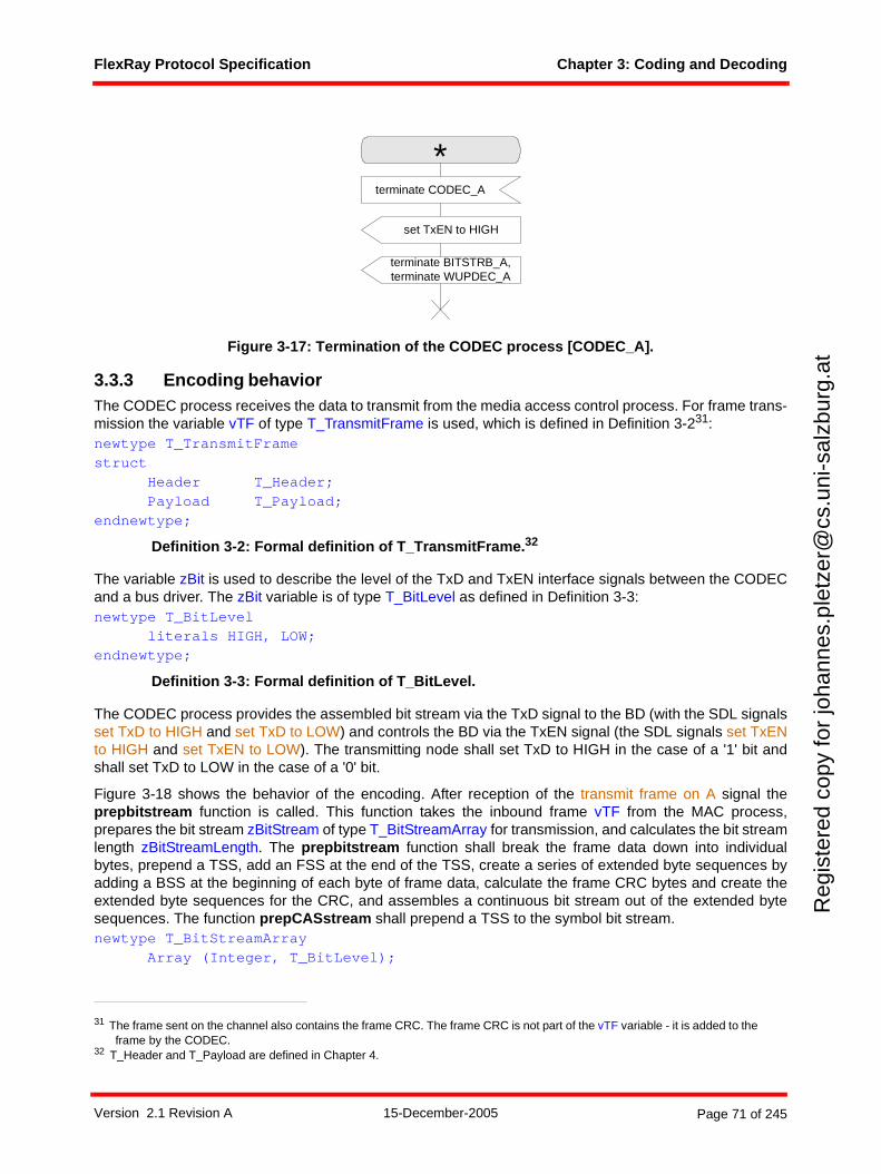
FlexRay Protocol Specification Chapter 3: Coding and Decoding
Reg
iste
red
copy
for
joha
nnes
.ple
tzer
@cs
.uni
-sal
zbur
g.at
Figure 3-17: Termination of the CODEC process [CODEC_A].
3.3.3 Encoding behaviorThe CODEC process receives the data to transmit from the media access control process. For frame trans-mission the variable vTF of type T_TransmitFrame is used, which is defined in Definition 3-231:newtype T_TransmitFramestruct
Header T_Header;Payload T_Payload;
endnewtype;
Definition 3-2: Formal definition of T_TransmitFrame.32
The variable zBit is used to describe the level of the TxD and TxEN interface signals between the CODECand a bus driver. The zBit variable is of type T_BitLevel as defined in Definition 3-3:newtype T_BitLevel
literals HIGH, LOW;endnewtype;
Definition 3-3: Formal definition of T_BitLevel.
The CODEC process provides the assembled bit stream via the TxD signal to the BD (with the SDL signalsset TxD to HIGH and set TxD to LOW) and controls the BD via the TxEN signal (the SDL signals set TxENto HIGH and set TxEN to LOW). The transmitting node shall set TxD to HIGH in the case of a '1' bit andshall set TxD to LOW in the case of a '0' bit.
Figure 3-18 shows the behavior of the encoding. After reception of the transmit frame on A signal theprepbitstream function is called. This function takes the inbound frame vTF from the MAC process,prepares the bit stream zBitStream of type T_BitStreamArray for transmission, and calculates the bit streamlength zBitStreamLength. The prepbitstream function shall break the frame data down into individualbytes, prepend a TSS, add an FSS at the end of the TSS, create a series of extended byte sequences byadding a BSS at the beginning of each byte of frame data, calculate the frame CRC bytes and create theextended byte sequences for the CRC, and assembles a continuous bit stream out of the extended bytesequences. The function prepCASstream shall prepend a TSS to the symbol bit stream.newtype T_BitStreamArray
Array (Integer, T_BitLevel);
31 The frame sent on the channel also contains the frame CRC. The frame CRC is not part of the vTF variable - it is added to the frame by the CODEC.
32 T_Header and T_Payload are defined in Chapter 4.
terminate CODEC_A
terminate BITSTRB_A,terminate WUPDEC_A
set TxEN to HIGH
*
Version 2.1 Revision A 15-December-2005 Page 71 of 245
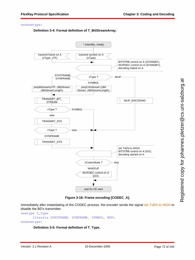
FlexRay Protocol Specification Chapter 3: Coding and Decoding
Reg
iste
red
copy
for
joha
nnes
.ple
tzer
@cs
.uni
-sal
zbur
g.at
endnewtype;
Definition 3-4: Formal definition of T_BitStreamArray.
Figure 3-18: Frame encoding [CODEC_A].
Immediately after instantiating of the CODEC process, the encoder sends the signal set TxEN to HIGH todisable the BD's transmitter.newtype T_Type
literals STATFRAME, DYNFRAME, SYMBOL, WUP;endnewtype;
Definition 3-5: Formal definition of T_Type.
* (standby, ready)
transmit symbol on A(vType)
prepbitstream(vTF, zBitStream,zBitStreamLength);
prepCASstream (zBitStream, zBitStreamLength);
TRANSMIT_BIT_STREAM
TRANSMIT_DTS
else
TRANSMIT_FES
DYNFRAME
SYMBOL
WUP_ENCODING
STATFRAME,DYNFRAME
vType ?
vType ?
WUP
vType ?
else
SYMBOL
wait for CE start
set TxEN to HIGH,BITSTRB control on A (GO),decoding started on A
transmit frame on A(vType, vTF)
zCodecMode ?
WUPDEC control on A(GO)
WAKEUP
else
BITSTRB control on A (STANDBY),WUPDEC control on A (STANDBY),decoding halted on A
Version 2.1 Revision A 15-December-2005 Page 72 of 245
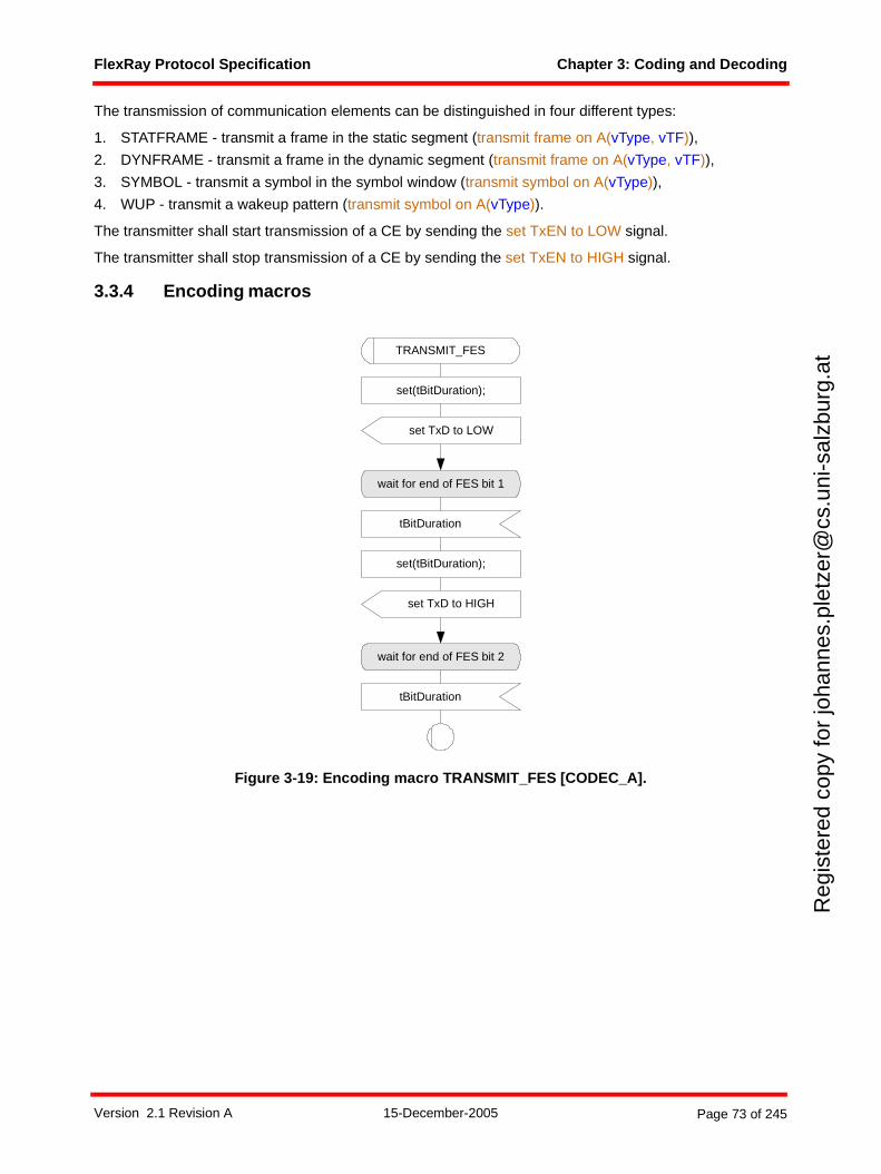
FlexRay Protocol Specification Chapter 3: Coding and Decoding
Reg
iste
red
copy
for
joha
nnes
.ple
tzer
@cs
.uni
-sal
zbur
g.at
The transmission of communication elements can be distinguished in four different types:
1. STATFRAME - transmit a frame in the static segment (transmit frame on A(vType, vTF)),
2. DYNFRAME - transmit a frame in the dynamic segment (transmit frame on A(vType, vTF)),
3. SYMBOL - transmit a symbol in the symbol window (transmit symbol on A(vType)),
4. WUP - transmit a wakeup pattern (transmit symbol on A(vType)).
The transmitter shall start transmission of a CE by sending the set TxEN to LOW signal.
The transmitter shall stop transmission of a CE by sending the set TxEN to HIGH signal.
3.3.4 Encoding macros
Figure 3-19: Encoding macro TRANSMIT_FES [CODEC_A].
TRANSMIT_FES
set(tBitDuration);
tBitDuration
wait for end of FES bit 2
set TxD to HIGH
set(tBitDuration);
wait for end of FES bit 1
set TxD to LOW
tBitDuration
Version 2.1 Revision A 15-December-2005 Page 73 of 245
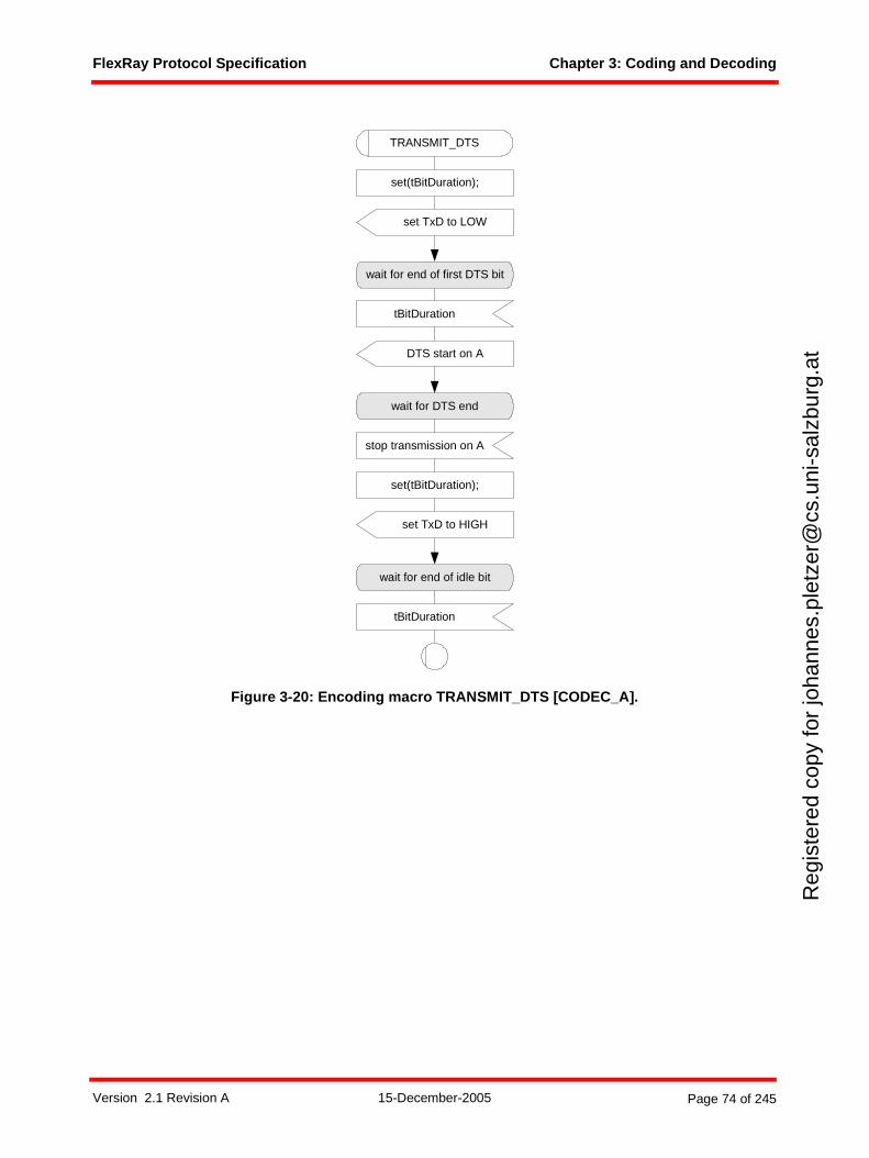
FlexRay Protocol Specification Chapter 3: Coding and Decoding
Reg
iste
red
copy
for
joha
nnes
.ple
tzer
@cs
.uni
-sal
zbur
g.at
Figure 3-20: Encoding macro TRANSMIT_DTS [CODEC_A].
TRANSMIT_DTS
set(tBitDuration);
tBitDuration
wait for end of first DTS bit
DTS start on A
stop transmission on A
wait for DTS end
set TxD to LOW
set(tBitDuration);
tBitDuration
wait for end of idle bit
set TxD to HIGH
Version 2.1 Revision A 15-December-2005 Page 74 of 245
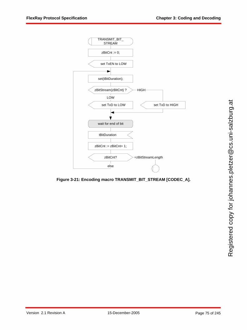
FlexRay Protocol Specification Chapter 3: Coding and Decoding
Reg
iste
red
copy
for
joha
nnes
.ple
tzer
@cs
.uni
-sal
zbur
g.at
Figure 3-21: Encoding macro TRANSMIT_BIT_STREAM [CODEC_A].
TRANSMIT_BIT_STREAM
set(tBitDuration);
tBitDuration
wait for end of bit
LOW
=zBitStreamLength
zBitCnt := 0;
zBitCnt?
zBitCnt := zBitCnt+ 1;
else
set TxEN to LOW
set TxD to LOW set TxD to HIGH
zBitStream(zBitCnt) ? HIGH
Version 2.1 Revision A 15-December-2005 Page 75 of 245
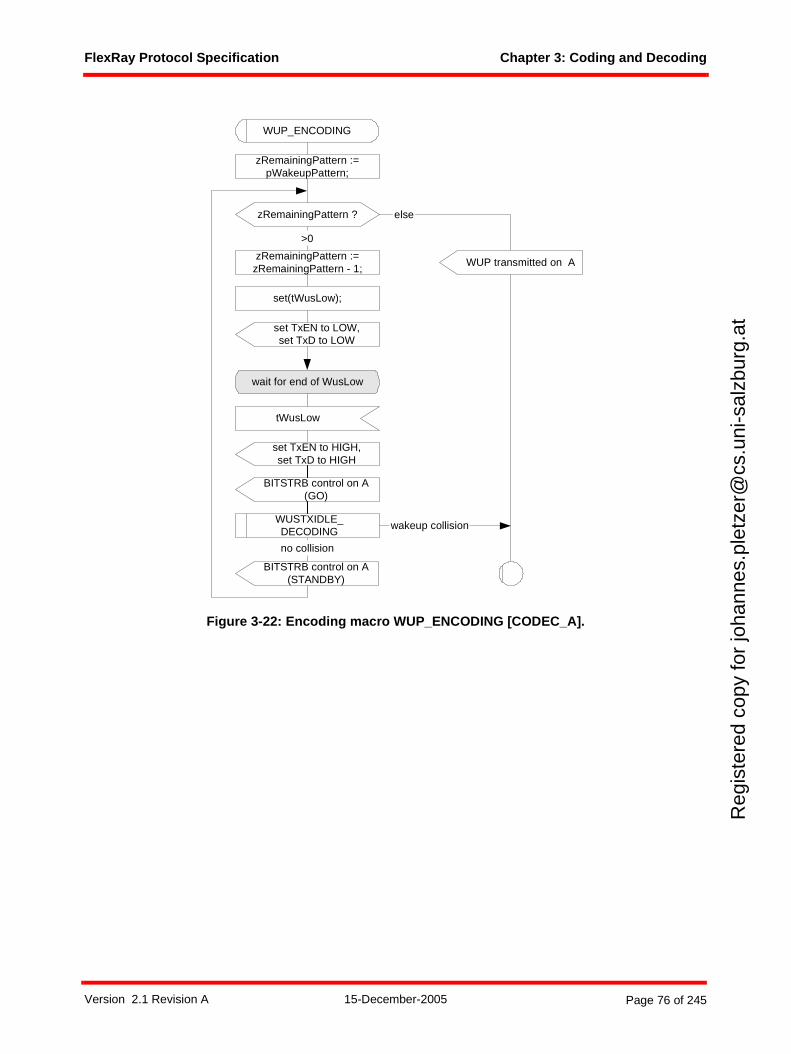
FlexRay Protocol Specification Chapter 3: Coding and Decoding
Reg
iste
red
copy
for
joha
nnes
.ple
tzer
@cs
.uni
-sal
zbur
g.at
Figure 3-22: Encoding macro WUP_ENCODING [CODEC_A].
zRemainingPattern :=pWakeupPattern;
>0
set TxEN to HIGH,set TxD to HIGH
WUP_ENCODING
zRemainingPattern ? else
zRemainingPattern :=zRemainingPattern - 1;
no collision
set(tWusLow);
tWusLow
wait for end of WusLow
set TxEN to LOW,set TxD to LOW
WUP transmitted on A
WUSTXIDLE_DECODING
wakeup collision
BITSTRB control on A(GO)
BITSTRB control on A(STANDBY)
Version 2.1 Revision A 15-December-2005 Page 76 of 245
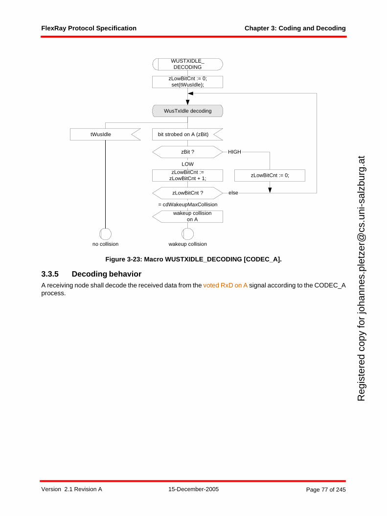
FlexRay Protocol Specification Chapter 3: Coding and Decoding
Reg
iste
red
copy
for
joha
nnes
.ple
tzer
@cs
.uni
-sal
zbur
g.at
Figure 3-23: Macro WUSTXIDLE_DECODING [CODEC_A].
3.3.5 Decoding behaviorA receiving node shall decode the received data from the voted RxD on A signal according to the CODEC_Aprocess.
WUSTXIDLE_DECODING
zBit ?
WusTxIdle decoding
bit strobed on A (zBit)
zLowBitCnt := 0;set(tWusIdle);
else
wakeup collision
zLowBitCnt ?
zLowBitCnt :=zLowBitCnt + 1;
wakeup collisionon A
= cdWakeupMaxCollision
LOW
HIGH
zLowBitCnt := 0;
tWusIdle
no collision
Version 2.1 Revision A 15-December-2005 Page 77 of 245
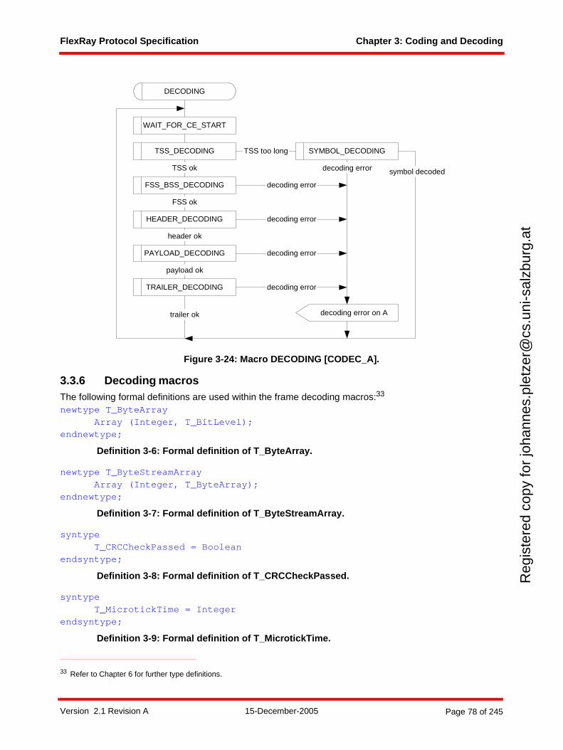
FlexRay Protocol Specification Chapter 3: Coding and Decoding
Reg
iste
red
copy
for
joha
nnes
.ple
tzer
@cs
.uni
-sal
zbur
g.at
Figure 3-24: Macro DECODING [CODEC_A].
3.3.6 Decoding macrosThe following formal definitions are used within the frame decoding macros:33
newtype T_ByteArrayArray (Integer, T_BitLevel);
endnewtype;
Definition 3-6: Formal definition of T_ByteArray.
newtype T_ByteStreamArrayArray (Integer, T_ByteArray);
endnewtype;
Definition 3-7: Formal definition of T_ByteStreamArray.
syntype T_CRCCheckPassed = Boolean
endsyntype;
Definition 3-8: Formal definition of T_CRCCheckPassed.
syntypeT_MicrotickTime = Integer
endsyntype;
Definition 3-9: Formal definition of T_MicrotickTime.
33 Refer to Chapter 6 for further type definitions.
WAIT_FOR_CE_START
SYMBOL_DECODINGTSS_DECODING TSS too long
FSS_BSS_DECODING
TSS ok
HEADER_DECODING
PAYLOAD_DECODING
FSS ok
header ok
payload ok
TRAILER_DECODING
trailer ok
symbol decoded
decoding error
decoding error
decoding error
decoding error
decoding error on A
decoding error
DECODING
Version 2.1 Revision A 15-December-2005 Page 78 of 245
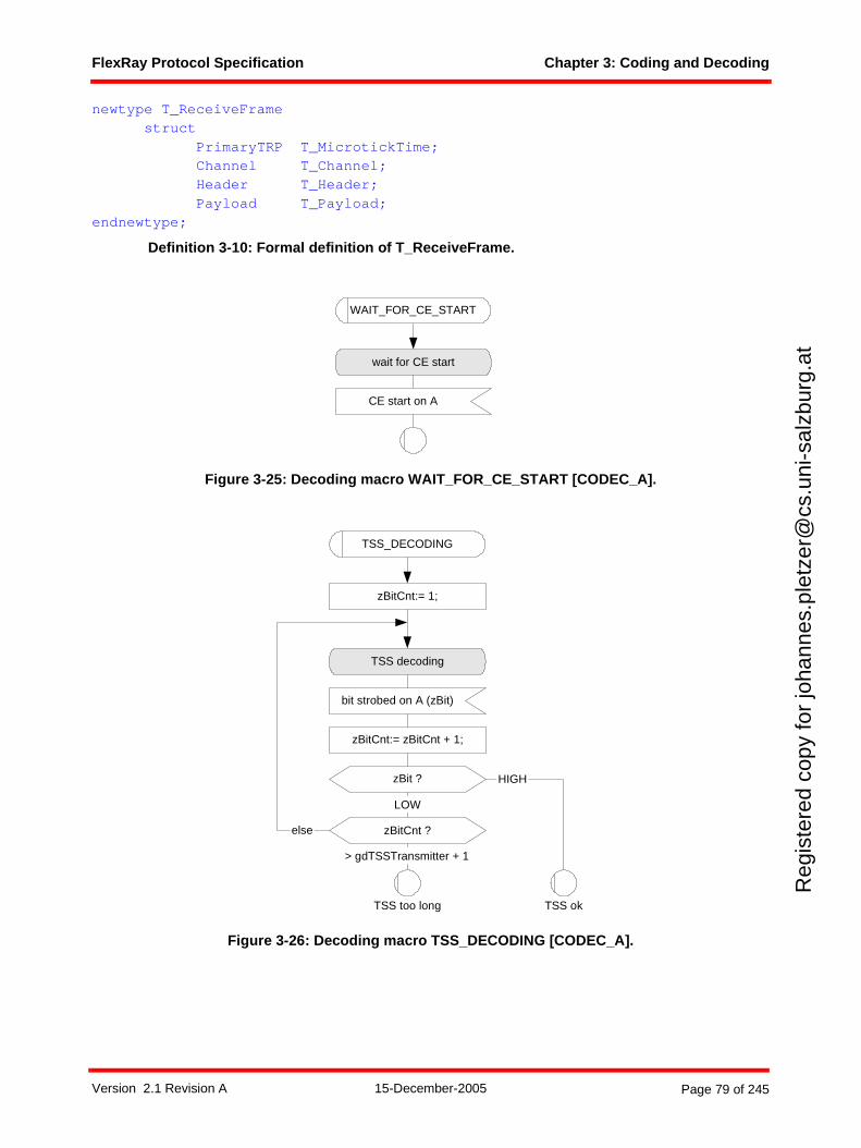
FlexRay Protocol Specification Chapter 3: Coding and Decoding
Reg
iste
red
copy
for
joha
nnes
.ple
tzer
@cs
.uni
-sal
zbur
g.at
newtype T_ReceiveFramestruct
PrimaryTRP T_MicrotickTime;Channel T_Channel;Header T_Header;Payload T_Payload;
endnewtype;
Definition 3-10: Formal definition of T_ReceiveFrame.
Figure 3-25: Decoding macro WAIT_FOR_CE_START [CODEC_A].
Figure 3-26: Decoding macro TSS_DECODING [CODEC_A].
wait for CE start
WAIT_FOR_CE_START
CE start on A
TSS_DECODING
bit strobed on A (zBit)
zBit ?
TSS decoding
LOW
zBitCnt:= 1;
zBitCnt:= zBitCnt + 1;
zBitCnt ?
HIGH
> gdTSSTransmitter + 1
TSS okTSS too long
else
Version 2.1 Revision A 15-December-2005 Page 79 of 245
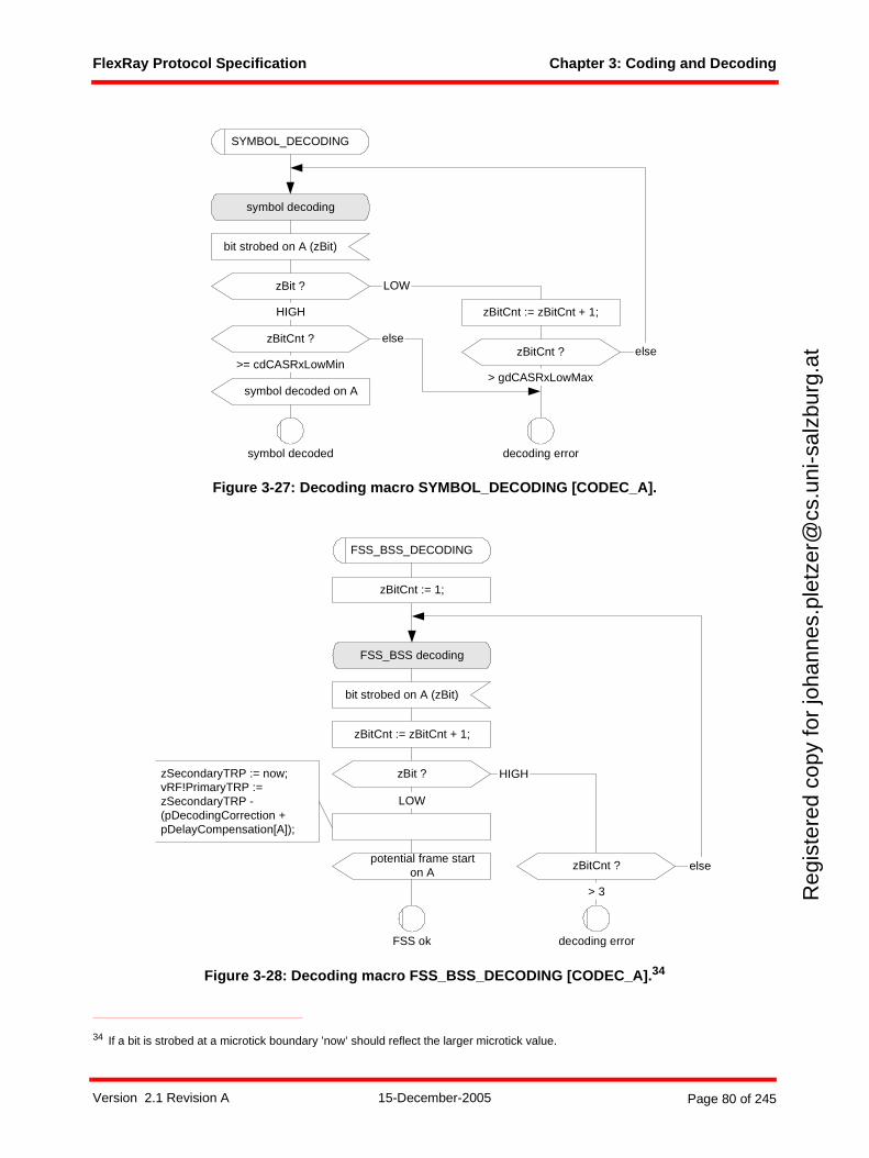
FlexRay Protocol Specification Chapter 3: Coding and Decoding
Reg
iste
red
copy
for
joha
nnes
.ple
tzer
@cs
.uni
-sal
zbur
g.at
Figure 3-27: Decoding macro SYMBOL_DECODING [CODEC_A].
Figure 3-28: Decoding macro FSS_BSS_DECODING [CODEC_A].34
34 If a bit is strobed at a microtick boundary ’now’ should reflect the larger microtick value.
SYMBOL_DECODING
bit strobed on A (zBit)
zBit ?
symbol decoding
elsezBitCnt ?
>= cdCASRxLowMin
symbol decoded on A> gdCASRxLowMax
symbol decoded decoding error
zBitCnt := zBitCnt + 1;HIGH
LOW
elsezBitCnt ?
FSS_BSS_DECODING
bit strobed on A (zBit)
FSS_BSS decoding
zBitCnt := zBitCnt + 1;
zBit ?
potential frame starton A
FSS ok
HIGH
zBitCnt ?
> 3
decoding error
else
LOW
zBitCnt := 1;
zSecondaryTRP := now;vRF!PrimaryTRP :=zSecondaryTRP -(pDecodingCorrection +pDelayCompensation[A]);
Version 2.1 Revision A 15-December-2005 Page 80 of 245
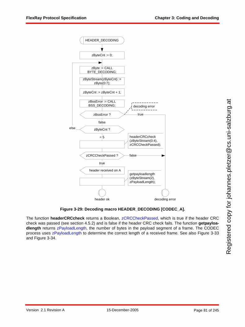
FlexRay Protocol Specification Chapter 3: Coding and Decoding
Reg
iste
red
copy
for
joha
nnes
.ple
tzer
@cs
.uni
-sal
zbur
g.at
Figure 3-29: Decoding macro HEADER_DECODING [CODEC_A].
The function headerCRCcheck returns a Boolean, zCRCCheckPassed, which is true if the header CRCcheck was passed (see section 4.5.2) and is false if the header CRC check fails. The function getpayloa-dlength returns zPayloadLength, the number of bytes in the payload segment of a frame. The CODECprocess uses zPayloadLength to determine the correct length of a received frame. See also Figure 3-33and Figure 3-34.
HEADER_DECODING
zByteCnt := 0;
false
zByteCnt ?
= 5
else
zCRCCheckPassed ?
true
false
header received on A
decoding errorheader ok
headerCRCcheck(zByteStream(0:4),zCRCCheckPassed);
getpayloadlength(zByteStream(2),zPayloadLength);
truezBssError ?
decoding error
zByteStream(zByteCnt) :=zByte(0:7);
zByteCnt := zByteCnt + 1;
zByte := CALLBYTE_DECODING;
zBssError := CALLBSS_DECODING;
Version 2.1 Revision A 15-December-2005 Page 81 of 245
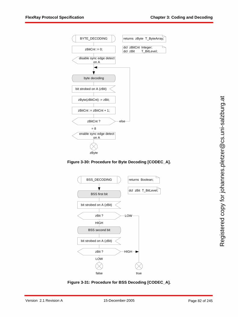
FlexRay Protocol Specification Chapter 3: Coding and Decoding
Reg
iste
red
copy
for
joha
nnes
.ple
tzer
@cs
.uni
-sal
zbur
g.at
Figure 3-30: Procedure for Byte Decoding [CODEC_A].
Figure 3-31: Procedure for BSS Decoding [CODEC_A].
bit strobed on A (zBit)
byte decoding
zBitCnt := 0;
zBitCnt := zBitCnt + 1;
zBitCnt ? else
zByte(zBitCnt) := zBit;
= 8
BYTE_DECODING
zByte
returns zByte T_ByteArray;
dcl zBitCnt Integer;dcl zBit T_BitLevel;
enable sync edge detecton A
disable sync edge detecton A
bit strobed on A (zBit)
zBit ?
BSS first bit
HIGH
LOW
bit strobed on A (zBit)
zBit ?
BSS second bit
LOW
HIGH
BSS_DECODING returns Boolean;
dcl zBit T_BitLevel;
truefalse
Version 2.1 Revision A 15-December-2005 Page 82 of 245
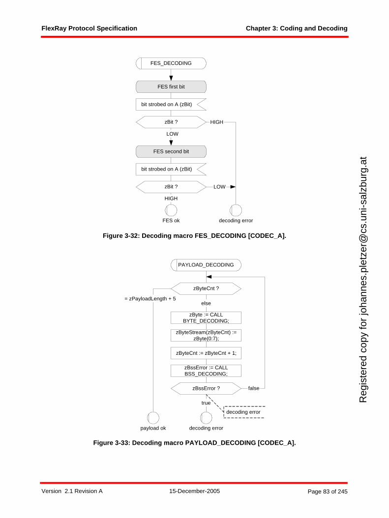
FlexRay Protocol Specification Chapter 3: Coding and Decoding
Reg
iste
red
copy
for
joha
nnes
.ple
tzer
@cs
.uni
-sal
zbur
g.at
Figure 3-32: Decoding macro FES_DECODING [CODEC_A].
Figure 3-33: Decoding macro PAYLOAD_DECODING [CODEC_A].
FES_DECODING
bit strobed on A (zBit)
zBit ?
FES first bit
LOW
bit strobed on A (zBit)
zBit ?
FES second bit
HIGH
FES ok
HIGH
LOW
decoding error
PAYLOAD_DECODING
true
false
zByteCnt ?
= zPayloadLength + 5else
decoding errorpayload ok
zBssError ?
decoding error
zByteStream(zByteCnt) :=zByte(0:7);
zByteCnt := zByteCnt + 1;
zByte := CALLBYTE_DECODING;
zBssError := CALLBSS_DECODING;
Version 2.1 Revision A 15-December-2005 Page 83 of 245
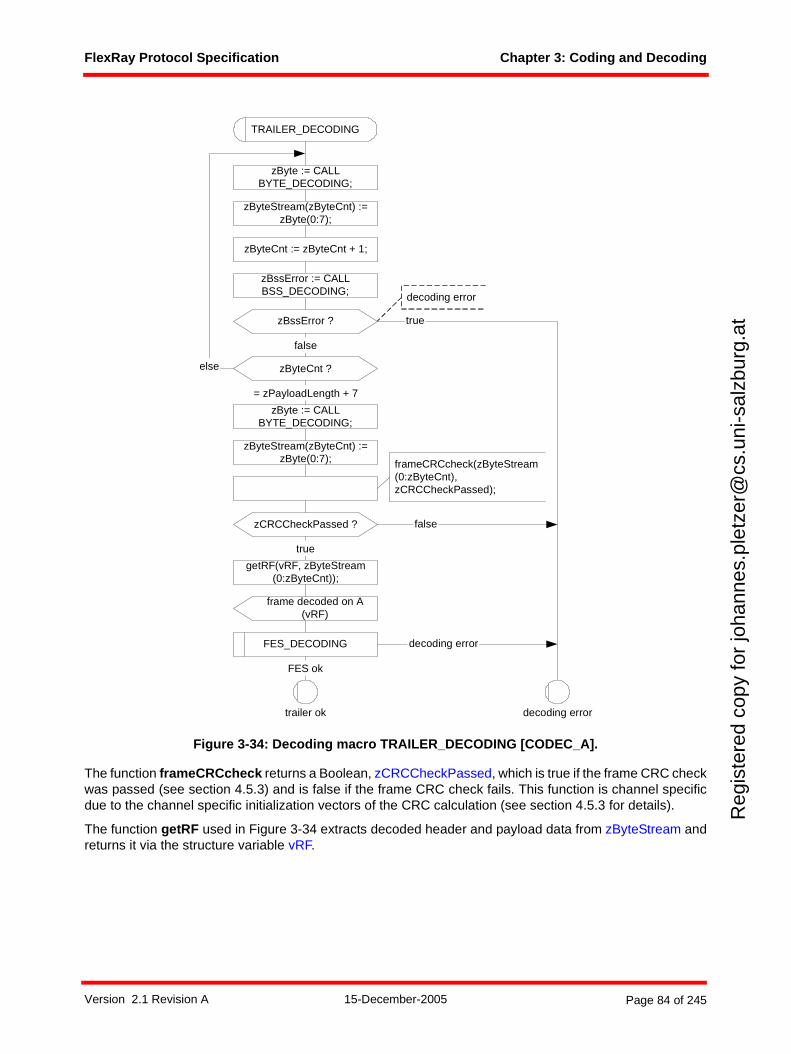
FlexRay Protocol Specification Chapter 3: Coding and Decoding
Reg
iste
red
copy
for
joha
nnes
.ple
tzer
@cs
.uni
-sal
zbur
g.at
Figure 3-34: Decoding macro TRAILER_DECODING [CODEC_A].
The function frameCRCcheck returns a Boolean, zCRCCheckPassed, which is true if the frame CRC checkwas passed (see section 4.5.3) and is false if the frame CRC check fails. This function is channel specificdue to the channel specific initialization vectors of the CRC calculation (see section 4.5.3 for details).
The function getRF used in Figure 3-34 extracts decoded header and payload data from zByteStream andreturns it via the structure variable vRF.
TRAILER_DECODING
true
false
zByteCnt ?
= zPayloadLength + 7
else
zCRCCheckPassed ?
true
false
frame decoded on A(vRF)
FES_DECODING decoding error
FES ok
getRF(vRF, zByteStream(0:zByteCnt));
decoding errortrailer ok
frameCRCcheck(zByteStream(0:zByteCnt),zCRCCheckPassed);
zBssError ?
decoding error
zByteStream(zByteCnt) :=zByte(0:7);
zByteCnt := zByteCnt + 1;
zByteStream(zByteCnt) :=zByte(0:7);
zByte := CALLBYTE_DECODING;
zByte := CALLBYTE_DECODING;
zBssError := CALLBSS_DECODING;
Version 2.1 Revision A 15-December-2005 Page 84 of 245
FlexRay Protocol Specification Chapter 3: Coding and Decoding
Reg
iste
red
copy
for
joha
nnes
.ple
tzer
@cs
.uni
-sal
zbur
g.at
3.4 Bit strobing process
3.4.1 Operating modesThe receiving node shall strobe the received data from the BD according to the bit strobing processBITSTRB. Definition 3-11 shows the formal definition of the BITSTRB operating modes: newtype T_StrbMode
literals STANDBY, GO;endnewtype;
Definition 3-11: Formal definition of T_StrbMode.
The bit strobing process BITSTRB has the following two operating modes:
1. In the STANDBY mode bit strobing is effectively halted.
2. In the GO mode the bit strobing process shall be executed.
At the transition from the state CODEC:standby to the state CODEC:ready the bit strobing processBITSTRB is set in the mode GO and at any transition of the CODEC process to CODEC:standby the bitstrobing process BITSTRB is set to STANDBY.
Version 2.1 Revision A 15-December-2005 Page 85 of 245
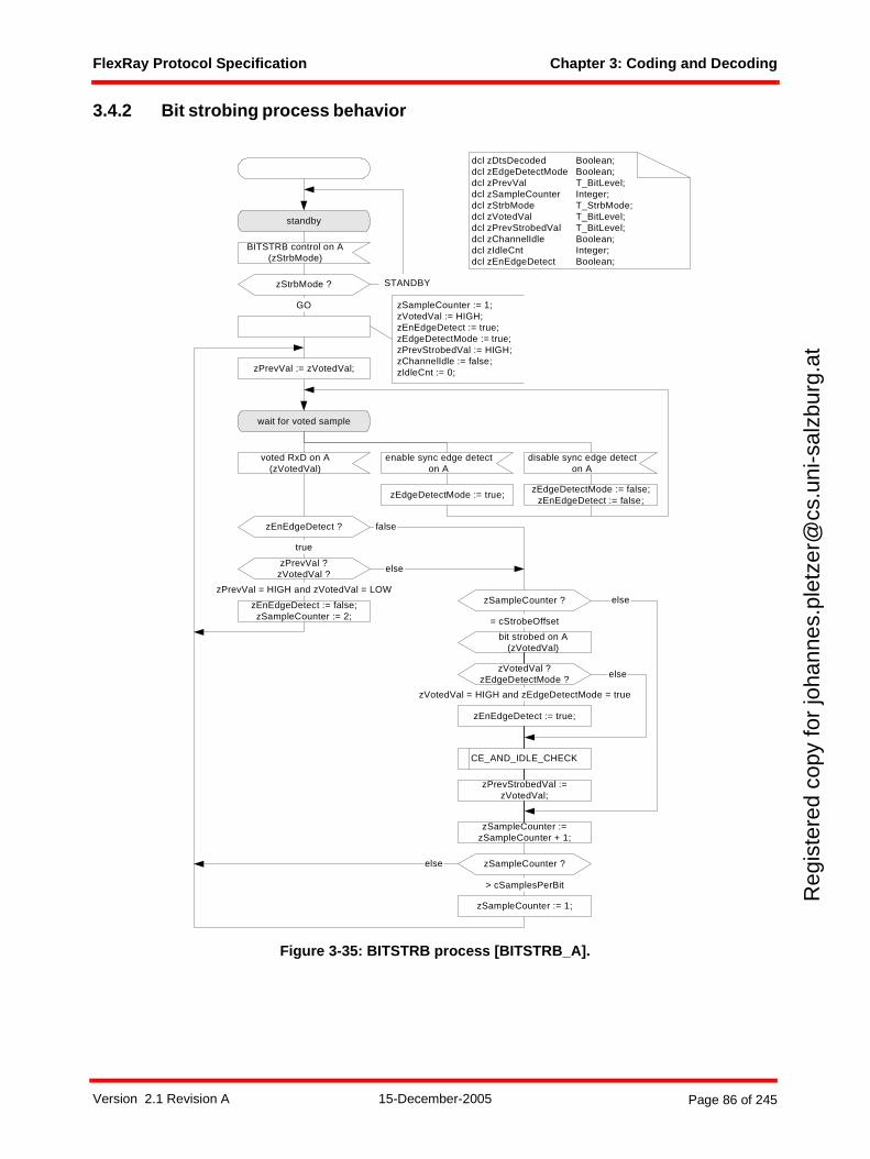
FlexRay Protocol Specification Chapter 3: Coding and Decoding
Reg
iste
red
copy
for
joha
nnes
.ple
tzer
@cs
.uni
-sal
zbur
g.at
3.4.2 Bit strobing process behavior
Figure 3-35: BITSTRB process [BITSTRB_A].
voted RxD on A(zVotedVal)
wait for voted sample
enable sync edge detecton A
zEdgeDetectMode := true;zEdgeDetectMode := false;
zEnEdgeDetect := false;
zEnEdgeDetect ? false
zPrevVal ?zVotedVal ?
true
else
zPrevVal = HIGH and zVotedVal = LOW
standby
BITSTRB control on A(zStrbMode)
zStrbMode ?
GO
zPrevVal := zVotedVal;
STANDBY
dcl zDtsDecoded Boolean;dcl zEdgeDetectMode Boolean;dcl zPrevVal T_BitLevel;dcl zSampleCounter Integer;dcl zStrbMode T_StrbMode;dcl zVotedVal T_BitLevel;dcl zPrevStrobedVal T_BitLevel;dcl zChannelIdle Boolean;dcl zIdleCnt Integer;dcl zEnEdgeDetect Boolean;
zSampleCounter := 1;zVotedVal := HIGH;zEnEdgeDetect := true;zEdgeDetectMode := true;zPrevStrobedVal := HIGH;zChannelIdle := false;zIdleCnt := 0;
disable sync edge detecton A
zEnEdgeDetect := false;zSampleCounter := 2;
zSampleCounter :=zSampleCounter + 1;
zSampleCounter ?
> cSamplesPerBit
zSampleCounter := 1;
zEnEdgeDetect := true;
zSampleCounter ?
bit strobed on A(zVotedVal)
= cStrobeOffset
else
CE_AND_IDLE_CHECK
zPrevStrobedVal :=zVotedVal;
zVotedVal ?zEdgeDetectMode ?
else
zVotedVal = HIGH and zEdgeDetectMode = true
else
Version 2.1 Revision A 15-December-2005 Page 86 of 245
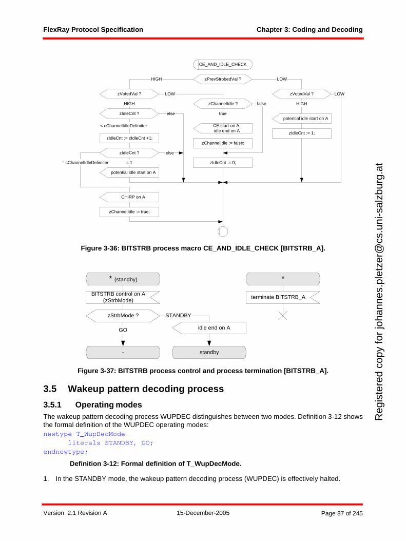
FlexRay Protocol Specification Chapter 3: Coding and Decoding
Reg
iste
red
copy
for
joha
nnes
.ple
tzer
@cs
.uni
-sal
zbur
g.at
Figure 3-36: BITSTRB process macro CE_AND_IDLE_CHECK [BITSTRB_A].
Figure 3-37: BITSTRB process control and process termination [BITSTRB_A].
3.5 Wakeup pattern decoding process
3.5.1 Operating modesThe wakeup pattern decoding process WUPDEC distinguishes between two modes. Definition 3-12 showsthe formal definition of the WUPDEC operating modes:newtype T_WupDecMode
literals STANDBY, GO;endnewtype;
Definition 3-12: Formal definition of T_WupDecMode.
1. In the STANDBY mode, the wakeup pattern decoding process (WUPDEC) is effectively halted.
CE start on A,idle end on A
zPrevStrobedVal ?
zVotedVal ? zVotedVal ?
HIGH LOW
LOW
zIdleCnt := 1;
potential idle start on A
HIGH
LOW
zIdleCnt ?
HIGH
else
zIdleCnt := zIdleCnt +1;
zIdleCnt ?
CHIRP on A
zChannelIdle := true;
< cChannelIdleDelimiter
= cChannelIdleDelimiter
else
zIdleCnt := 0;
CE_AND_IDLE_CHECK
zChannelIdle ?
true
false
= 1
potential idle start on A
zChannelIdle := false;
* (standby)
BITSTRB control on A(zStrbMode)
zStrbMode ?
-
GO
standby
STANDBY
*
terminate BITSTRB_A
idle end on A
Version 2.1 Revision A 15-December-2005 Page 87 of 245
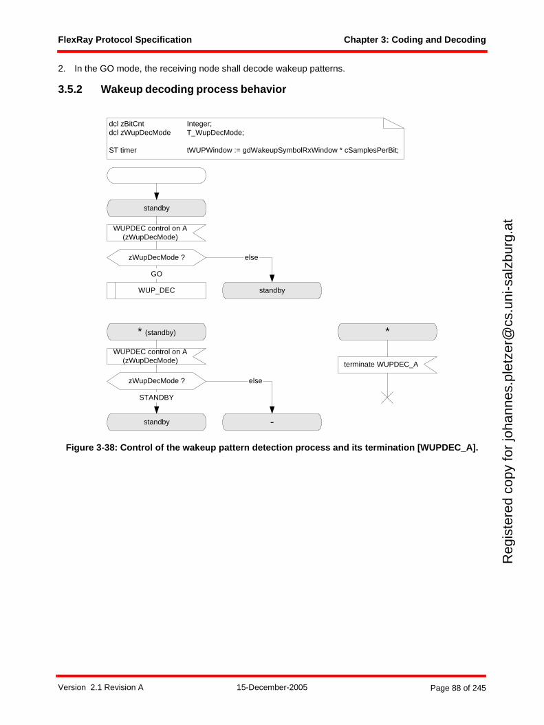
FlexRay Protocol Specification Chapter 3: Coding and Decoding
Reg
iste
red
copy
for
joha
nnes
.ple
tzer
@cs
.uni
-sal
zbur
g.at
2. In the GO mode, the receiving node shall decode wakeup patterns.
3.5.2 Wakeup decoding process behavior
Figure 3-38: Control of the wakeup pattern detection process and its termination [WUPDEC_A].
standby
WUPDEC control on A(zWupDecMode)
WUP_DEC
terminate WUPDEC_A
dcl zBitCnt Integer;dcl zWupDecMode T_WupDecMode;
ST timer tWUPWindow := gdWakeupSymbolRxWindow * cSamplesPerBit;
*
zWupDecMode ?
GO
standby
else
* (standby)
WUPDEC control on A(zWupDecMode)
zWupDecMode ?
STANDBY
-
else
standby
Version 2.1 Revision A 15-December-2005 Page 88 of 245
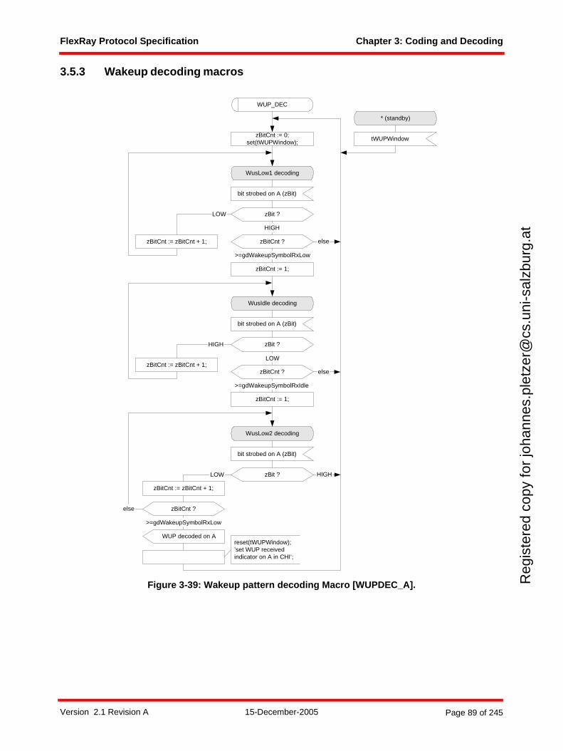
FlexRay Protocol Specification Chapter 3: Coding and Decoding
Reg
iste
red
copy
for
joha
nnes
.ple
tzer
@cs
.uni
-sal
zbur
g.at
3.5.3 Wakeup decoding macros
Figure 3-39: Wakeup pattern decoding Macro [WUPDEC_A].
WUP_DEC
bit strobed on A (zBit)
zBit ?
WusLow1 decoding
LOW
HIGH
zBitCnt ?
>=gdWakeupSymbolRxLow
else
zBitCnt := 0;set(tWUPWindow);
zBitCnt := zBitCnt + 1;
zBit ?
WusIdle decoding
LOW
>=gdWakeupSymbolRxIdle
bit strobed on A (zBit)
zBitCnt := 1;
HIGH
zBitCnt ?zBitCnt := zBitCnt + 1;
bit strobed on A (zBit)
zBit ?
WusLow2 decoding
LOW
zBitCnt := zBitCnt + 1;
zBitCnt := 1;
zBitCnt ?
HIGH
else
>=gdWakeupSymbolRxLow
WUP decoded on A
* (standby)
tWUPWindow
else
reset(tWUPWindow);’set WUP receivedindicator on A in CHI’;
Version 2.1 Revision A 15-December-2005 Page 89 of 245
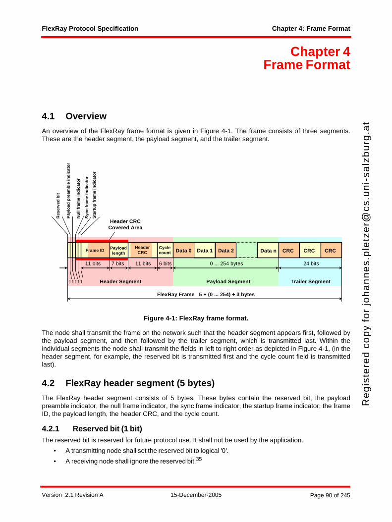
FlexRay Protocol Specification Chapter 4: Frame Format
Re
gis
tere
d c
op
y fo
r jo
ha
nn
es.
ple
tze
r@cs
.un
i-sa
lzb
urg
.at
Chapter 4Frame Format
4.1 Overview
An overview of the FlexRay frame format is given in Figure 4-1. The frame consists of three segments.These are the header segment, the payload segment, and the trailer segment.
Figure 4-1: FlexRay frame format.
The node shall transmit the frame on the network such that the header segment appears first, followed bythe payload segment, and then followed by the trailer segment, which is transmitted last. Within theindividual segments the node shall transmit the fields in left to right order as depicted in Figure 4-1, (in theheader segment, for example, the reserved bit is transmitted first and the cycle count field is transmittedlast).
4.2 FlexRay header segment (5 bytes)
The FlexRay header segment consists of 5 bytes. These bytes contain the reserved bit, the payloadpreamble indicator, the null frame indicator, the sync frame indicator, the startup frame indicator, the frameID, the payload length, the header CRC, and the cycle count.
4.2.1 Reserved bit (1 bit)The reserved bit is reserved for future protocol use. It shall not be used by the application.
• A transmitting node shall set the reserved bit to logical '0'.
• A receiving node shall ignore the reserved bit.35
CRC CRC
24 bits
Data nFrame ID
7 bits 0 ... 254 bytes
Cyclecount CRC
FlexRay Frame 5 + (0 ... 254) + 3 bytes
Payloadlength
11 bits 6 bits
Syn
c fr
ame
ind
icat
or
11 bits
HeaderCRC
Nu
ll fr
ame
ind
icat
or
Header Segment Payload Segment Trailer Segment
Header CRCCovered Area
Pay
load
pre
amb
le in
dic
ato
r
Res
erve
d b
it
11111
Sta
rtu
p f
ram
e in
dic
ato
r
Data 0 Data 1 Data 2
Version 2.1 Revision A 15-December-2005 Page 90 of 245
FlexRay Protocol Specification Chapter 4: Frame Format
Reg
iste
red
copy
for
joha
nnes
.ple
tzer
@cs
.uni
-sal
zbur
g.at
syntype T_Reserved = Integerconstants 0 : 1
endsyntype;
Definition 4-1: Formal definition of T_Reserved.
4.2.2 Payload preamble indicator (1 bit)The payload preamble indicator indicates whether or not an optional vector is contained within the payloadsegment of the frame transmitted36:
• If the frame is transmitted in the static segment the payload preamble indicator indicates thepresence of a network management vector at the beginning of the payload.
• If the frame is transmitted in the dynamic segment the payload preamble indicator indicates thepresence of a message ID at the beginning of the payload.
If the payload preamble indicator is set to zero then the payload segment of the frame does not contain anetwork management vector or a message ID, respectively.
If the payload preamble indicator is set to one then the payload segment of the frame contains a networkmanagement vector if it is transmitted in the static segment or a message ID if it is transmitted in the dynamicsegment.syntype T_PPIndicator = Integer
constants 0 : 1endsyntype;
Definition 4-2: Formal definition of T_PPIndicator.
4.2.3 Null frame indicator (1 bit)The null frame indicator indicates whether or not the frame is a null frame, i.e. a frame that contains nouseable data in the payload segment of the frame.37 The conditions under which a transmitting node maysend a null frame are detailed in Chapter 5. Nodes that receive a null frame may still use some informationrelated to the frame.38
• If the null frame indicator is set to zero then the payload segment contains no valid data. All bytes inthe payload section are set to zero.
• If the null frame indicator is set to one then the payload segment contains data.syntype T_NFIndicator = Integer
constants 0 : 1endsyntype;
Definition 4-3: Formal definition of T_NFIndicator.
4.2.4 Sync frame indicator (1 bit)The sync frame indicator indicates whether or not the frame is a sync frame, i.e. a frame that is utilized forsystem wide synchronization of communication.39
35 The receiving node uses the value of the reserved bit for the Frame CRC checking process, but otherwise ignores its value (i.e., the receiver shall accept either a 1 or a 0 in this field).
36 If the null frame indicator is set to zero the payload preamble indicator is irrelevant because the payload contains no usable data.
37 The null frame indicator indicates only whether payload data was available to the communication controller at the time the frame was sent. A null frame indicator set to zero informs the receiving node(s) that data in the payload segment must not be used. If the bit is set to one data is present in the payload segment from the transmitting communication controller's perspective. The receiving node may still have to do additional checks to decide whether the data is actually valid from an application perspective.
38 For example, the clock synchronization algorithm will use the arrival time of null frames with the Sync frame indicator set to one (provided all other criteria for that frame's acceptance are met).
Version 2.1 Revision A 15-December-2005 Page 91 of 245

FlexRay Protocol Specification Chapter 4: Frame Format
Reg
iste
red
copy
for
joha
nnes
.ple
tzer
@cs
.uni
-sal
zbur
g.at
• If the sync frame indicator is set to zero then no receiving node shall consider the frame for synchro-nization or synchronization related tasks.
• If the sync frame indicator is set to one then all receiving nodes shall utilize the frame for synchroni-zation if it meets other acceptance criteria (see below).
The clock synchronization mechanism (described in Chapter 8) makes use of the sync frame indicator.There are several conditions that result in the sync frame indicator being set to one and subsequentlyutilized by the clock synchronization mechanism. Details of how the node shall set the sync frame indicatorare specified in Chapter 5 and section 8.8.syntype T_SyFIndicator = Integer
constants 0 : 1endsyntype;
Definition 4-4: Formal definition of T_SyFIndicator.
4.2.5 Startup frame indicator (1 bit)The startup frame indicator indicates whether or not a frame is a startup frame. Startup frames serve aspecial role in the startup mechanism (see Chapter 7). Only coldstart nodes are allow to transmit startupframes.
• If the startup frame indicator is set to zero then the frame is not a startup frame.
• If the startup frame indicator is set to one then the frame is a startup frame.
The startup frame indicator shall only be set to one in the sync frames of coldstart nodes. Therefore, a framewith the startup frame indicator set to one shall also have the sync frame indicator set to one.
Since the startup frame indicator can only be set to one in sync frames, every coldstart node can transmitexactly one frame per communication cycle and channel with the startup frame indicator set to one.
The startup (described in Chapter 7) and clock synchronization (described in Chapter 8) mechanisms utilizethe startup frame indicator. In both cases, the condition that the startup frame indicator is set to one is onlyone of several conditions necessary for the frame to be used by the mechanisms. Details regarding how thenode sets the startup frame indicator are specified in Chapter 5.40 syntype T_SuFIndicator = Integer
constants 0 : 1endsyntype;
Definition 4-5: Formal definition of T_SuFIndicator.
4.2.6 Frame ID (11 bits)The frame ID defines the slot in which the frame should be transmitted. A frame ID is used no more thanonce on each channel in a communication cycle. Each frame that may be transmitted in a cluster has aframe ID assigned to it.
The frame ID ranges from 1 to 204741. The frame ID 0 is an invalid frame ID42.
The node shall transmit the frame ID such that the most significant bit of the frame ID is transmitted first withthe remaining bits of the frame ID being transmitted in decreasing order of significance.
39 Sync frames may only sent in the static segment. Please refer to the rules to configure sync frames.40 The configuration of exactly three nodes in a cluster as coldstart nodes avoids the formation of cliques during startup for
several fault scenarios. It is also possible to configure more than three nodes as coldstart nodes but the clique avoidance mechanism will not work in this case.
41 In binary: from (000 0000 0001)2 to (111 1111 1111)242 The frame ID of a transmitted frame is determined by the value of vSlotCounter(Ch) at the time of transmission (see Chapter
5). In the absence of faults, vSlotCounter(Ch) can never be zero when a slot is available for transmission. Received frames with frame ID zero will always be identified as erroneous because a slot ID mismatch is a certainty due to the fact that there is no slot with ID zero.
Version 2.1 Revision A 15-December-2005 Page 92 of 245
FlexRay Protocol Specification Chapter 4: Frame Format
Reg
iste
red
copy
for
joha
nnes
.ple
tzer
@cs
.uni
-sal
zbur
g.at
syntype T_FrameID = Integerconstants 0 : 204743
endsyntype;
Definition 4-6: Formal definition of T_FrameID.
4.2.7 Payload length (7 bits)The payload length field is used to indicate the size of the payload segment. The payload segment size isencoded in this field by setting it to the number of payload data bytes divided by two (e.g., a frame thatcontains a payload segment consisting of 72 bytes would be sent with the payload length set to 36).44
The payload length ranges from 0 to cPayloadLengthMax, which corresponds to a payload segmentcontaining 2 * cPayloadLengthMax bytes.
The payload length shall be fixed and identical for all frames sent in the static segment of a communicationcycle. For these frames the payload length field shall be transmitted with the payload length set to gPayload-LengthStatic.
The payload length may be different for different frames in the dynamic segment of a communication cycle.In addition, the payload length of a specific dynamic segment frame may vary from cycle to cycle. Finally,the payload lengths of a specific dynamic segment frame may be different on each configured channel.
The node shall transmit the payload length such that the most significant bit of the payload length is trans-mitted first with the remaining bits of the payload length being transmitted in decreasing order of signifi-cance.syntype T_Length = Integer
constants 0 : cPayloadLengthMaxendsyntype;
Definition 4-7: Formal definition of T_Length.
4.2.8 Header CRC (11 bits)The header CRC contains a cyclic redundancy check code (CRC) that is computed over the sync frameindicator, the startup frame indicator, the frame ID, and the payload length. The CC shall not calculate theheader CRC for a transmitted frame. The header CRC of transmitted frames is computed offline andprovided to the CC by means of configuration (i.e., it is not computed by the transmitting CC).45 The CCshall calculate the header CRC of a received frame in order to check that the CRC is correct.
The CRC is computed in the same manner for all configured channels. The CRC polynomial46 shall be
The initialization vector of the register used to generate the header CRC shall be 0x01A.
43 Frame IDs range from 1 to 2047. The zero is used to mark invalid frames, empty slots, etc.44 The payload length field does not include the number of bytes within the header and the trailer segments of the FlexRay
frame.45 For a given frame in the static segment the values of the header fields covered by the CRC do not change during the
operation of the cluster in the absence of faults. Implicitly, the CRC does not need to change either. Offline calculation of the CRC makes it unlikely that a fault-induced change to the covered header fields will also result in a frame with a valid header CRC (since the CRC is not recalculated based on the modified header fields).
46 This 11 bit CRC polynomial generates a (31,20) BCH code that has a minimum Hamming distance of 6. The codeword consists of the data to be protected and the CRC. In this application, this CRC protects exactly 20 bits of data (1 sync frame indicator bit + 1 startup frame indicator bit + 11 frame ID bits + 7 payload length bits = 20 bits). This polynomial was obtained from [Wad01] and its properties were verified using the techniques described in [Koo02].
x11
x9
x8
x7
x2
1+ + + + + x 1+( ) x5
x3
1+ +( ) x5
x4
x3
x 1+ + + +( )⋅ ⋅=
Version 2.1 Revision A 15-December-2005 Page 93 of 245
FlexRay Protocol Specification Chapter 4: Frame Format
Reg
iste
red
copy
for
joha
nnes
.ple
tzer
@cs
.uni
-sal
zbur
g.at
With respect to the computation of the header CRC, the sync frame indicator shall be shifted in first, followedby the startup frame indicator, followed by the most significant bit of the frame ID, followed by subsequentbits of the frame ID, followed by the most significant bit of the payload length, and followed by subsequentbits of the payload length.
The node shall transmit the header CRC such that the most significant bit of the header CRC is transmittedfirst with the remaining bits of the header CRC being transmitted in decreasing order of significance.
A detailed description of how to generate and verify the header CRC is given in section 4.5.2.syntype T_HeaderCRC = Integer
constants 0 : 2047 endsyntype;
Definition 4-8: Formal definition of T_HeaderCRC.
4.2.9 Cycle count (6 bits)The cycle count indicates the transmitting node's view of the value of the cycle counter vCycleCounter atthe time of frame transmission (see section 5.3.2.2 and section 5.3.3.2).
The node shall transmit the cycle count such that the most significant bit of the cycle count is transmittedfirst with the remaining bits of the cycle count being transmitted in decreasing order of significance.syntype T_CycleCounter = Integer
constants 0 : 63 endsyntype;
Definition 4-9: Formal definition of T_CycleCounter.
4.2.10 Formal header definitionThe formal definitions of the fields in the previous sections and the header segment structure depicted inFigure 4-1 yield the following formal definition for the header segment:newtype T_Headerstruct
Reserved T_Reserved;PPIndicator T_PPIndicator;NFIndicator T_NFIndicator;SyFIndicator T_SyFIndicator;SuFIndicator T_SuFIndicator;FrameID T_FrameID;Length T_Length;HeaderCRC T_HeaderCRC;CycleCount T_CycleCounter;
endnewtype;
Definition 4-10: Formal definition of T_Header.
4.3 FlexRay payload segment (0 - 254 bytes)
The FlexRay payload segment contains 0 to 254 bytes (0 to 127 two-byte words) of data. Because thepayload length contains the number of two-byte words, the payload segment contains an even number ofbytes.47 The bytes of the payload segment are identified numerically, starting at 0 for the first byte after theheader segment and increasing by one with each subsequent byte. The individual bytes are referred to as"Data 0", "Data 1", "Data 2", etc., with "Data 0" being the first byte of the payload segment, "Data 1" beingthe second byte, etc.
Version 2.1 Revision A 15-December-2005 Page 94 of 245
FlexRay Protocol Specification Chapter 4: Frame Format
Reg
iste
red
copy
for
joha
nnes
.ple
tzer
@cs
.uni
-sal
zbur
g.at
The frame CRC described in section 4.5.3 has a Hamming distance of six for payload lengths up to andincluding 248 bytes. For payload lengths greater than 248 bytes the CRC has a Hamming distance of four.
For frames transmitted in the dynamic segment the first two bytes of the payload segment may optionallybe used as a message ID field, allowing receiving nodes to filter or steer data based on the contents of thisfield. The payload preamble indicator in the frame header indicates whether the payload segment containsthe message ID.
For frames transmitted in the static segment the first 0 to 12 bytes of the payload segment may optionallybe used as a network management vector. The payload preamble indicator in the frame header indicateswhether the payload segment contains the network management vector48. The length of the networkmanagement vector gNetworkManagementVectorLength is configured during the POC:config state andcannot be changed in any other state. gNetworkManagementVectorLength can be configured between 0and 12 bytes, inclusive.
Starting with payload "Data 0" the node shall transmit the bytes of the payload segment such that the mostsignificant bit of the byte is transmitted first with the remaining bits of the byte being transmitted indecreasing order of significance.49
The product specific host interface specification determines the mapping between the position of bytes inthe buffer and the position of the bytes in the payload segment of the frame.newtype T_Payload
Array(T_Length, Integer)endnewtype;
Definition 4-11: Formal definition of T_Payload.
4.3.1 NMVector (optional)A number of bytes in the payload segment of the FlexRay frame format in a frame transmitted in the staticsegment can be used as Network Management Vector (NMVector).
• The length of the NMVector is configured during POC:config by the parameter gNetworkManage-mentVectorLength. All nodes in a cluster must be configured with the same value for this parameter.
• The NMVector may only be used in frames transmitted in the static segment.
• At the transmitting node the NMVector is written by the host as application data. The communica-tion controller has no knowledge about the NMVector and no mechanism inside the communicationcontroller is based on the NMVector except the ORing function described in section 9.3.3.4.
• The optional presence of NMVector is indicated in the frame header by the payload preambleindicator.
• The bits in a byte of the NMVector shall be transmitted such that the most significant bit of a byte istransmitted first followed by the remaining bits being transmitted in decreasing order of significance.
• The least significant byte of the NMVector is transmitted first followed by the remaining bytes inincreasing order of significance.50
47 The length of the payload segment indicated by the Length field of the T_Header structure corresponds to the number of bytes that are sent on the communication channel. It does not necessarily correspond to the number of bytes used by the application in the payload segment. The data provided by the application may be shorter than the payload segment. A padding function in the communication controller fills the "missing" bytes if the configured transmit buffer is smaller than the configured payload length.
48 Frames that contain network management data are not restricted to contain only network management data - the other bytes in the payload segment may be used to convey additional, non-Network Management data.
49 If a message ID exists, the most significant byte of the message ID is transmitted first followed by the least significant byte of the message ID. If no message ID exists the transmission starts with the first payload data byte (Data 0) followed by the remaining payload data bytes.
50 This allows lower bits to remain at defined positions if the length of the NMvector changes.
Version 2.1 Revision A 15-December-2005 Page 95 of 245
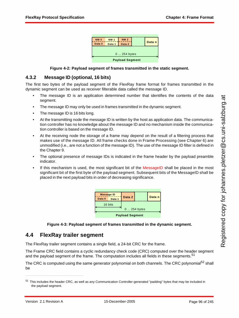
FlexRay Protocol Specification Chapter 4: Frame Format
Reg
iste
red
copy
for
joha
nnes
.ple
tzer
@cs
.uni
-sal
zbur
g.at
Figure 4-2: Payload segment of frames transmitted in the static segment.
4.3.2 Message ID (optional, 16 bits) The first two bytes of the payload segment of the FlexRay frame format for frames transmitted in thedynamic segment can be used as receiver filterable data called the message ID.
• The message ID is an application determined number that identifies the contents of the datasegment.
• The message ID may only be used in frames transmitted in the dynamic segment.
• The message ID is 16 bits long.
• At the transmitting node the message ID is written by the host as application data. The communica-tion controller has no knowledge about the message ID and no mechanism inside the communica-tion controller is based on the message ID.
• At the receiving node the storage of a frame may depend on the result of a filtering process thatmakes use of the message ID. All frame checks done in Frame Processing (see Chapter 6) areunmodified (i.e., are not a function of the message ID). The use of the message ID filter is defined inthe Chapter 9.
• The optional presence of message IDs is indicated in the frame header by the payload preambleindicator.
• If this mechanism is used, the most significant bit of the MessageID shall be placed in the mostsignificant bit of the first byte of the payload segment. Subsequent bits of the MessageID shall beplaced in the next payload bits in order of decreasing significance.
Figure 4-3: Payload segment of frames transmitted in the dynamic segment.
4.4 FlexRay trailer segment
The FlexRay trailer segment contains a single field, a 24-bit CRC for the frame.
The Frame CRC field contains a cyclic redundancy check code (CRC) computed over the header segmentand the payload segment of the frame. The computation includes all fields in these segments.51
The CRC is computed using the same generator polynomial on both channels. The CRC polynomial52 shallbe
51 This includes the header CRC, as well as any Communication Controller-generated "padding" bytes that may be included in the payload segment.
Data n
0 ... 254 bytes
Payload Segment
Data 0 Data 1 Data 2
NM 2NM 1NM 0
Data n
0 ... 254 bytes
16 bits
Message ID
Payload Segment
Data 0 Data 1Data 2
Version 2.1 Revision A 15-December-2005 Page 96 of 245
FlexRay Protocol Specification Chapter 4: Frame Format
Reg
iste
red
copy
for
joha
nnes
.ple
tzer
@cs
.uni
-sal
zbur
g.at
The node shall use a different initialization vector depending on which channel the frame should be trans-mitted53:
• The node shall use the initialization vector 0xFEDCBA for frames sent on channel A.
• The node shall use the initialization vector 0xABCDEF for frames sent on channel B.
With respect to the computation of the frame CRC, the frame fields shall be fed into the CRC generator innetwork order starting with the reserved bit, and ending with the least significant bit of the last byte of thepayload segment.
The frame CRC shall be transmitted such that the most significant bit of the frame CRC is transmitted firstwith the remaining bits of the frame CRC being transmitted in decreasing order of significance.
A detailed description of how to generate or verify the Frame CRC is given in section 4.5.3.syntype T_FrameCRC = Integer
constants 0x000000 : 0xFFFFFFendsyntype;
Definition 4-12: Formal definition of T_FrameCRC.
4.5 CRC calculation details
The behavior of the CODEC while processing a received frame depends on whether or not the receivedheader and frame CRCs are verified to match the values locally calculated using the actual frame data (seeFigure 3-29 and Figure 3-34). The CODEC also appends the CRC in the trailer segment of a transmittedframe (see section 3.2.1.1.6). The algorithm executed to calculate the CRC is the same in all cases exceptfor the initial values of several algorithm parameters (see below).
4.5.1 CRC calculation algorithmInitialize the CRC shift register with the appropriate initialization value. As long as bits (vNextBit) from theheader or payload segment of the frame are available the while-loop is executed. The number of bitsavailable in the payload segment is derived from the payload length field. The bits54 of the header andpayload segments are fed into the CRC register by using the variable vNextBit, bit by bit, in network order,e.g., for the FlexRay frame CRC calculation the first bit used as vNextBit is the reserved bit field, and thelast bit used is the least significant bit of the last byte of the payload segment.
The following pseudo code summarizes the CRC calculation algorithm:
vCrcReg(vCrcSize - 1 : 0) = vCrcInit; // Initialize the CRC register
while(vNextBit)
52 This 24-bit CRC polynomial generates a code that has a minimum Hamming distance of 6 for codewords up to 2048 bits in length and a minimum Hamming distance of 4 for codewords up to 4094 bits in length. The codeword consists of all frame data and the CRC. This corresponds to H=6 protection for FlexRay frames with payload lengths up to 248 bytes and H=4 protection for longer payload lengths. This polynomial was obtained from [Cas93], and its properties were verified using the techniques described in [Koo02].
53 Different initialization vectors are defined to prevent a node from communicating if it has crossed channels, connection of a single channel node to the wrong channel, or shorted channels (both controller channels connected to the same physical channel).
54 Transmitting nodes use the bit sequence that will be fed into the coding algorithm (see Chapter 3), including any controller generated padding bits. Receivers use the decoded sequence as received from the decoding algorithm (i.e., after the removal of any coding sequences (e.g. Byte Start Sequences, Frame Start Sequences, etc.)).
x24
x22
x20
x19
x18
x16
x14
x13
x11
x10
x8
x7
x6
x3
x 1+ + + + + + + + + + + + + + +
x 1+( )2x
11x
9x
8x
7x
5x
3x
2x 1+ + + + + + + +( ) x
11x
9x
8x
7x
6x
31+ + + + + +( )⋅ ⋅=
Version 2.1 Revision A 15-December-2005 Page 97 of 245
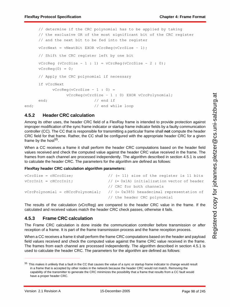
FlexRay Protocol Specification Chapter 4: Frame Format
Reg
iste
red
copy
for
joha
nnes
.ple
tzer
@cs
.uni
-sal
zbur
g.at
// determine if the CRC polynomial has to be applied by taking
// the exclusive OR of the most significant bit of the CRC register
// and the next bit to be fed into the register
vCrcNext = vNextBit EXOR vCrcReg(vCrcSize - 1);
// Shift the CRC register left by one bit
vCrcReg (vCrcSize - 1 : 1) = vCrcReg(vCrcSize - 2 : 0);
vCrcReg(0) = 0;
// Apply the CRC polynomial if necessary
if vCrcNext vCrcReg(vCrcSize - 1 : 0) =
vCrcReg(vCrcSize - 1 : 0) EXOR vCrcPolynomial;
end; // end if
end; // end while loop
4.5.2 Header CRC calculationAmong its other uses, the header CRC field of a FlexRay frame is intended to provide protection againstimproper modification of the sync frame indicator or startup frame indicator fields by a faulty communicationcontroller (CC). The CC that is responsible for transmitting a particular frame shall not compute the headerCRC field for that frame. Rather, the CC shall be configured with the appropriate header CRC for a givenframe by the host55.
When a CC receives a frame it shall perform the header CRC computations based on the header fieldvalues received and check the computed value against the header CRC value received in the frame. Theframes from each channel are processed independently. The algorithm described in section 4.5.1 is usedto calculate the header CRC. The parameters for the algorithm are defined as follows:
FlexRay header CRC calculation algorithm parameters:
vCrcSize = cHCrcSize; // (= 11) size of the register is 11 bits
vCrcInit = cHCrcInit; // (= 0x1A) initialization vector of header
// CRC for both channels
vCrcPolynomial = cHCrcPolynomial; // (= 0x385) hexadecimal representation of
// the header CRC polynomial
The results of the calculation (vCrcReg) are compared to the header CRC value in the frame. If thecalculated and received values match the header CRC check passes, otherwise it fails.
4.5.3 Frame CRC calculationThe Frame CRC calculation is done inside the communication controller before transmission or afterreception of a frame. It is part of the frame transmission process and the frame reception process.
When a CC receives a frame it shall perform the frame CRC computations based on the header and payloadfield values received and check the computed value against the frame CRC value received in the frame.The frames from each channel are processed independently. The algorithm described in section 4.5.1 isused to calculate the header CRC. The parameters for the algorithm are defined as follows:
55 This makes it unlikely that a fault in the CC that causes the value of a sync or startup frame indicator to change would result in a frame that is accepted by other nodes in the network because the header CRC would not match. Removing the capability of the transmitter to generate the CRC minimizes the possibility that a frame that results from a CC fault would have a proper header CRC.
Version 2.1 Revision A 15-December-2005 Page 98 of 245
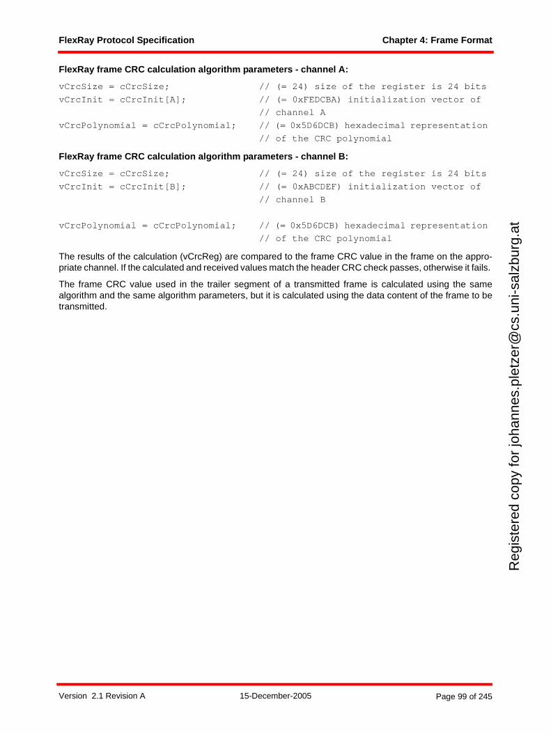
FlexRay Protocol Specification Chapter 4: Frame Format
Reg
iste
red
copy
for
joha
nnes
.ple
tzer
@cs
.uni
-sal
zbur
g.at
FlexRay frame CRC calculation algorithm parameters - channel A:
vCrcSize = cCrcSize; // (= 24) size of the register is 24 bits
vCrcInit = cCrcInit[A]; // (= 0xFEDCBA) initialization vector of
// channel A
vCrcPolynomial = cCrcPolynomial; // (= 0x5D6DCB) hexadecimal representation
// of the CRC polynomial
FlexRay frame CRC calculation algorithm parameters - channel B:
vCrcSize = cCrcSize; // (= 24) size of the register is 24 bits
vCrcInit = cCrcInit[B]; // (= 0xABCDEF) initialization vector of
// channel B
vCrcPolynomial = cCrcPolynomial; // (= 0x5D6DCB) hexadecimal representation
// of the CRC polynomial
The results of the calculation (vCrcReg) are compared to the frame CRC value in the frame on the appro-priate channel. If the calculated and received values match the header CRC check passes, otherwise it fails.
The frame CRC value used in the trailer segment of a transmitted frame is calculated using the samealgorithm and the same algorithm parameters, but it is calculated using the data content of the frame to betransmitted.
Version 2.1 Revision A 15-December-2005 Page 99 of 245
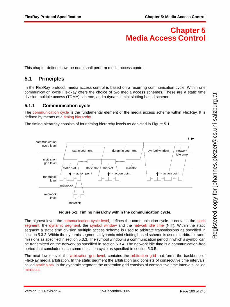
FlexRay Protocol Specification Chapter 5: Media Access Control
Reg
iste
red
copy
for
joha
nnes
.ple
tzer
@cs
.uni
-sal
zbur
g.at
Chapter 5Media Access Control
This chapter defines how the node shall perform media access control.
5.1 Principles
In the FlexRay protocol, media access control is based on a recurring communication cycle. Within onecommunication cycle FlexRay offers the choice of two media access schemes. These are a static timedivision multiple access (TDMA) scheme, and a dynamic mini-slotting based scheme.
5.1.1 Communication cycleThe communication cycle is the fundamental element of the media access scheme within FlexRay. It isdefined by means of a timing hierarchy.
The timing hierarchy consists of four timing hierarchy levels as depicted in Figure 5-1.
Figure 5-1: Timing hierarchy within the communication cycle.
The highest level, the communication cycle level, defines the communication cycle. It contains the staticsegment, the dynamic segment, the symbol window and the network idle time (NIT). Within the staticsegment a static time division multiple access scheme is used to arbitrate transmissions as specified insection 5.3.2. Within the dynamic segment a dynamic mini-slotting based scheme is used to arbitrate trans-missions as specified in section 5.3.3. The symbol window is a communication period in which a symbol canbe transmitted on the network as specified in section 5.3.4. The network idle time is a communication-freeperiod that concludes each communication cycle as specified in section 5.3.5.
The next lower level, the arbitration grid level, contains the arbitration grid that forms the backbone ofFlexRay media arbitration. In the static segment the arbitration grid consists of consecutive time intervals,called static slots, in the dynamic segment the arbitration grid consists of consecutive time intervals, calledminislots.
macrotick
arbitrationgrid level
macroticklevel
microticklevel
communicationcycle level
static segment dynamic segment
minislot
microtick
symbol window
t
action point
static slot static slot minislot
action point action point
networkidle time
Version 2.1 Revision A 15-December-2005 Page 100 of 245
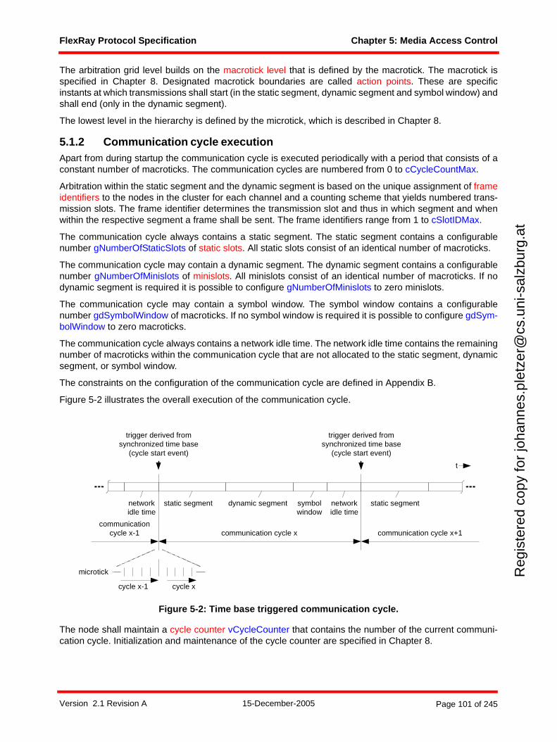
FlexRay Protocol Specification Chapter 5: Media Access Control
Reg
iste
red
copy
for
joha
nnes
.ple
tzer
@cs
.uni
-sal
zbur
g.at
The arbitration grid level builds on the macrotick level that is defined by the macrotick. The macrotick isspecified in Chapter 8. Designated macrotick boundaries are called action points. These are specificinstants at which transmissions shall start (in the static segment, dynamic segment and symbol window) andshall end (only in the dynamic segment).
The lowest level in the hierarchy is defined by the microtick, which is described in Chapter 8.
5.1.2 Communication cycle executionApart from during startup the communication cycle is executed periodically with a period that consists of aconstant number of macroticks. The communication cycles are numbered from 0 to cCycleCountMax.
Arbitration within the static segment and the dynamic segment is based on the unique assignment of frameidentifiers to the nodes in the cluster for each channel and a counting scheme that yields numbered trans-mission slots. The frame identifier determines the transmission slot and thus in which segment and whenwithin the respective segment a frame shall be sent. The frame identifiers range from 1 to cSlotIDMax.
The communication cycle always contains a static segment. The static segment contains a configurablenumber gNumberOfStaticSlots of static slots. All static slots consist of an identical number of macroticks.
The communication cycle may contain a dynamic segment. The dynamic segment contains a configurablenumber gNumberOfMinislots of minislots. All minislots consist of an identical number of macroticks. If nodynamic segment is required it is possible to configure gNumberOfMinislots to zero minislots.
The communication cycle may contain a symbol window. The symbol window contains a configurablenumber gdSymbolWindow of macroticks. If no symbol window is required it is possible to configure gdSym-bolWindow to zero macroticks.
The communication cycle always contains a network idle time. The network idle time contains the remainingnumber of macroticks within the communication cycle that are not allocated to the static segment, dynamicsegment, or symbol window.
The constraints on the configuration of the communication cycle are defined in Appendix B.
Figure 5-2 illustrates the overall execution of the communication cycle.
Figure 5-2: Time base triggered communication cycle.
The node shall maintain a cycle counter vCycleCounter that contains the number of the current communi-cation cycle. Initialization and maintenance of the cycle counter are specified in Chapter 8.
cycle x
communication cycle x communication cycle x+1
trigger derived fromsynchronized time base
(cycle start event)
trigger derived fromsynchronized time base
(cycle start event)
communicationcycle x-1
microtick
cycle x-1
static segment dynamic segment symbolwindow
networkidle time
static segmentnetworkidle time
t
Version 2.1 Revision A 15-December-2005 Page 101 of 245
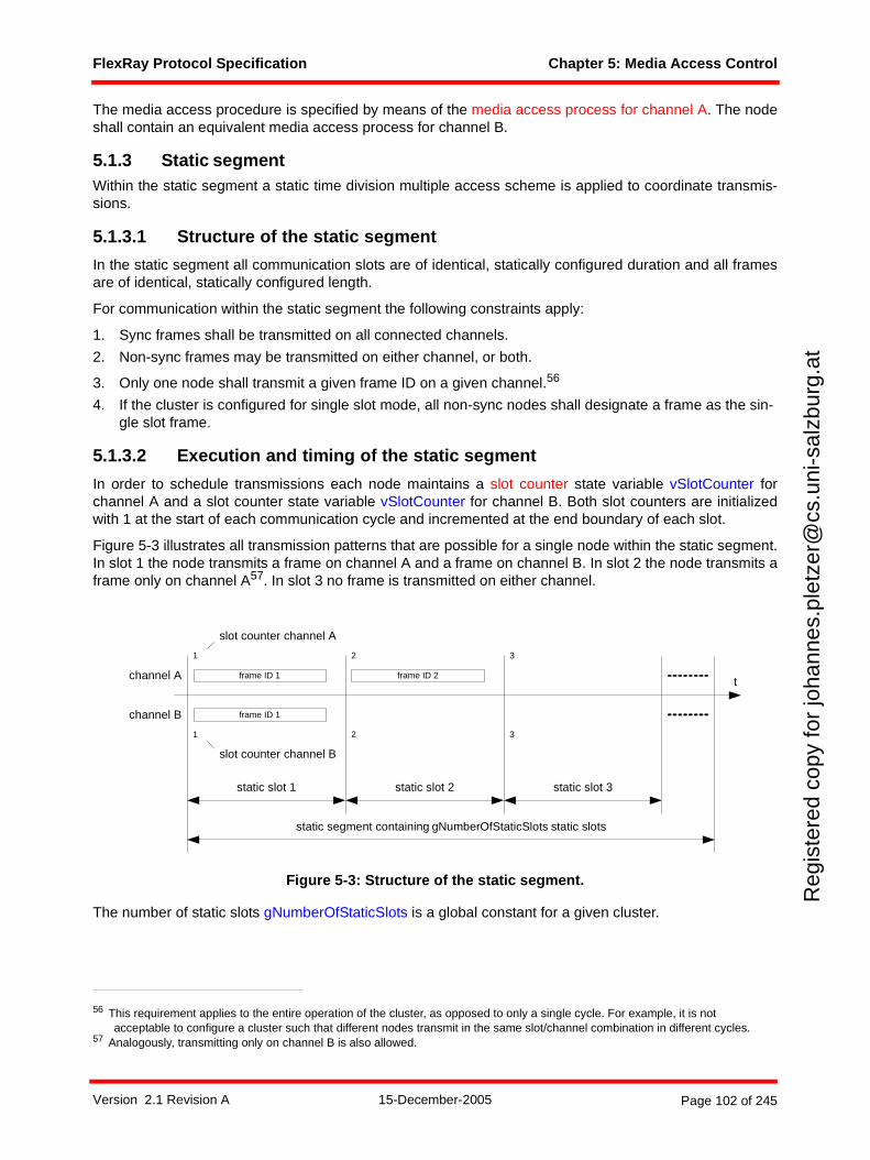
FlexRay Protocol Specification Chapter 5: Media Access Control
Reg
iste
red
copy
for
joha
nnes
.ple
tzer
@cs
.uni
-sal
zbur
g.at
The media access procedure is specified by means of the media access process for channel A. The nodeshall contain an equivalent media access process for channel B.
5.1.3 Static segmentWithin the static segment a static time division multiple access scheme is applied to coordinate transmis-sions.
5.1.3.1 Structure of the static segment
In the static segment all communication slots are of identical, statically configured duration and all framesare of identical, statically configured length.
For communication within the static segment the following constraints apply:
1. Sync frames shall be transmitted on all connected channels.
2. Non-sync frames may be transmitted on either channel, or both.
3. Only one node shall transmit a given frame ID on a given channel.56
4. If the cluster is configured for single slot mode, all non-sync nodes shall designate a frame as the sin-gle slot frame.
5.1.3.2 Execution and timing of the static segment
In order to schedule transmissions each node maintains a slot counter state variable vSlotCounter forchannel A and a slot counter state variable vSlotCounter for channel B. Both slot counters are initializedwith 1 at the start of each communication cycle and incremented at the end boundary of each slot.
Figure 5-3 illustrates all transmission patterns that are possible for a single node within the static segment.In slot 1 the node transmits a frame on channel A and a frame on channel B. In slot 2 the node transmits aframe only on channel A57. In slot 3 no frame is transmitted on either channel.
Figure 5-3: Structure of the static segment.
The number of static slots gNumberOfStaticSlots is a global constant for a given cluster.
56 This requirement applies to the entire operation of the cluster, as opposed to only a single cycle. For example, it is not acceptable to configure a cluster such that different nodes transmit in the same slot/channel combination in different cycles.
57 Analogously, transmitting only on channel B is also allowed.
channel A
channel B
frame ID 1
frame ID 1
frame ID 2
static segment containing gNumberOfStaticSlots static slots
static slot 1 static slot 2 static slot 3
t
1
1
2
2
3
3
slot counter channel A
slot counter channel B
Version 2.1 Revision A 15-December-2005 Page 102 of 245
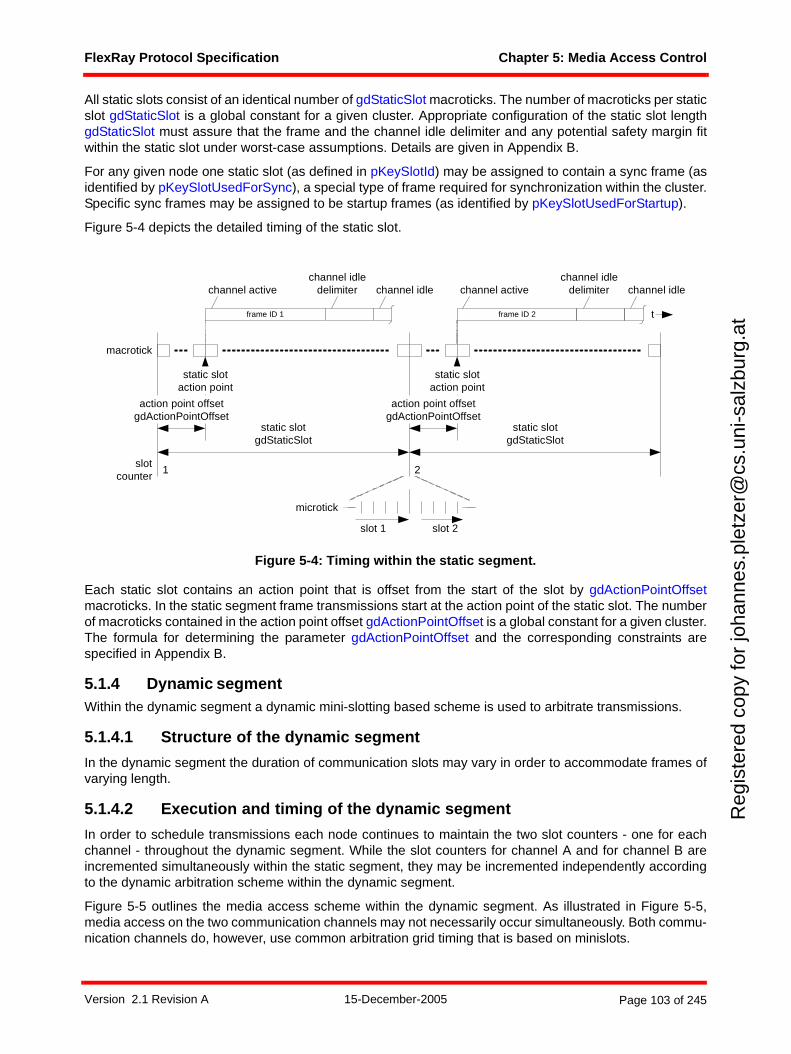
FlexRay Protocol Specification Chapter 5: Media Access Control
Reg
iste
red
copy
for
joha
nnes
.ple
tzer
@cs
.uni
-sal
zbur
g.at
All static slots consist of an identical number of gdStaticSlot macroticks. The number of macroticks per staticslot gdStaticSlot is a global constant for a given cluster. Appropriate configuration of the static slot lengthgdStaticSlot must assure that the frame and the channel idle delimiter and any potential safety margin fitwithin the static slot under worst-case assumptions. Details are given in Appendix B.
For any given node one static slot (as defined in pKeySlotId) may be assigned to contain a sync frame (asidentified by pKeySlotUsedForSync), a special type of frame required for synchronization within the cluster.Specific sync frames may be assigned to be startup frames (as identified by pKeySlotUsedForStartup).
Figure 5-4 depicts the detailed timing of the static slot.
Figure 5-4: Timing within the static segment.
Each static slot contains an action point that is offset from the start of the slot by gdActionPointOffsetmacroticks. In the static segment frame transmissions start at the action point of the static slot. The numberof macroticks contained in the action point offset gdActionPointOffset is a global constant for a given cluster.The formula for determining the parameter gdActionPointOffset and the corresponding constraints arespecified in Appendix B.
5.1.4 Dynamic segmentWithin the dynamic segment a dynamic mini-slotting based scheme is used to arbitrate transmissions.
5.1.4.1 Structure of the dynamic segment
In the dynamic segment the duration of communication slots may vary in order to accommodate frames ofvarying length.
5.1.4.2 Execution and timing of the dynamic segment
In order to schedule transmissions each node continues to maintain the two slot counters - one for eachchannel - throughout the dynamic segment. While the slot counters for channel A and for channel B areincremented simultaneously within the static segment, they may be incremented independently accordingto the dynamic arbitration scheme within the dynamic segment.
Figure 5-5 outlines the media access scheme within the dynamic segment. As illustrated in Figure 5-5,media access on the two communication channels may not necessarily occur simultaneously. Both commu-nication channels do, however, use common arbitration grid timing that is based on minislots.
frame ID 1
macrotick
static slotaction point
slotcounter
action point offsetgdActionPointOffset
static slotgdStaticSlot
1
channel idledelimiter channel idlechannel active
frame ID 2
static slotaction point
action point offsetgdActionPointOffset
static slotgdStaticSlot
2
channel idledelimiter channel idlechannel active
slot 2
microtick
slot 1
t
Version 2.1 Revision A 15-December-2005 Page 103 of 245
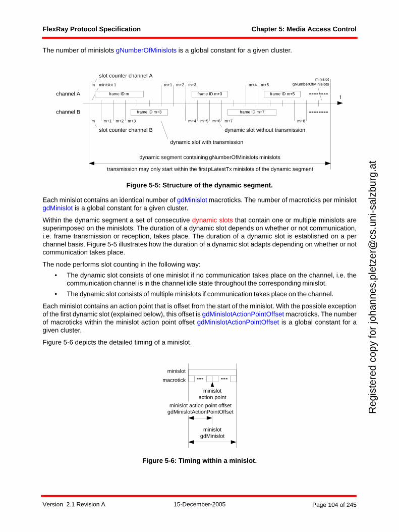
FlexRay Protocol Specification Chapter 5: Media Access Control
Reg
iste
red
copy
for
joha
nnes
.ple
tzer
@cs
.uni
-sal
zbur
g.at
The number of minislots gNumberOfMinislots is a global constant for a given cluster.
Figure 5-5: Structure of the dynamic segment.
Each minislot contains an identical number of gdMinislot macroticks. The number of macroticks per minislotgdMinislot is a global constant for a given cluster.
Within the dynamic segment a set of consecutive dynamic slots that contain one or multiple minislots aresuperimposed on the minislots. The duration of a dynamic slot depends on whether or not communication,i.e. frame transmission or reception, takes place. The duration of a dynamic slot is established on a perchannel basis. Figure 5-5 illustrates how the duration of a dynamic slot adapts depending on whether or notcommunication takes place.
The node performs slot counting in the following way:
• The dynamic slot consists of one minislot if no communication takes place on the channel, i.e. thecommunication channel is in the channel idle state throughout the corresponding minislot.
• The dynamic slot consists of multiple minislots if communication takes place on the channel.
Each minislot contains an action point that is offset from the start of the minislot. With the possible exceptionof the first dynamic slot (explained below), this offset is gdMinislotActionPointOffset macroticks. The numberof macroticks within the minislot action point offset gdMinislotActionPointOffset is a global constant for agiven cluster.
Figure 5-6 depicts the detailed timing of a minislot.
Figure 5-6: Timing within a minislot.
channel A
channel B frame ID m+3
frame ID m+3
frame ID m+7
frame ID m+5t
m
slot counter channel A
m+1 m+2 m+3 m+4 m+5
m m+1 m+2 m+4 m+5 m+6 m+7 m+8
slot counter channel B
dynamic segment containing gNumberOfMinislots minislots
m+3
dynamic slot with transmission
dynamic slot without transmission
minislot 1
transmission may only start within the first pLatestTx minislots of the dynamic segment
minislotgNumberOfMinislots
frame ID m
macrotick
minislot
minislotgdMinislot
minislot action point offsetgdMinislotActionPointOffset
minislotaction point
Version 2.1 Revision A 15-December-2005 Page 104 of 245
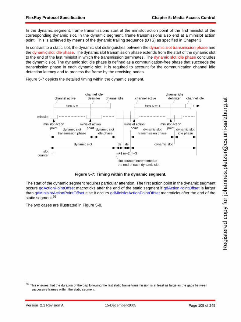
FlexRay Protocol Specification Chapter 5: Media Access Control
Reg
iste
red
copy
for
joha
nnes
.ple
tzer
@cs
.uni
-sal
zbur
g.at
In the dynamic segment, frame transmissions start at the minislot action point of the first minislot of thecorresponding dynamic slot. In the dynamic segment, frame transmissions also end at a minislot actionpoint. This is achieved by means of the dynamic trailing sequence (DTS) as specified in Chapter 3.
In contrast to a static slot, the dynamic slot distinguishes between the dynamic slot transmission phase andthe dynamic slot idle phase. The dynamic slot transmission phase extends from the start of the dynamic slotto the end of the last minislot in which the transmission terminates. The dynamic slot idle phase concludesthe dynamic slot. The dynamic slot idle phase is defined as a communication-free phase that succeeds thetransmission phase in each dynamic slot. It is required to account for the communication channel idledetection latency and to process the frame by the receiving nodes.
Figure 5-7 depicts the detailed timing within the dynamic segment.
Figure 5-7: Timing within the dynamic segment.
The start of the dynamic segment requires particular attention. The first action point in the dynamic segmentoccurs gdActionPointOffset macroticks after the end of the static segment if gdActionPointOffset is largerthan gdMinislotActionPointOffset else it occurs gdMinislotActionPointOffset macroticks after the end of thestatic segment.58
The two cases are illustrated in Figure 5-8.
58 This ensures that the duration of the gap following the last static frame transmission is at least as large as the gaps between successive frames within the static segment.
dynamic slot
minislot actionpoint
ds
frame ID m+3
slotcounter
ds
m m+1 m+2 m+3
slot counter incremented atthe end of each dynamic slot
frame ID m
channel idledelimiter channel idlechannel active
dynamic slot
minislot actionpoint
channel idledelimiterchannel active channel idle
minislot
t
minislot actionpointdynamic slot
transmission phasedynamic slotidle phase
minislot actionpointdynamic slot
transmission phasedynamic slotidle phase
Version 2.1 Revision A 15-December-2005 Page 105 of 245
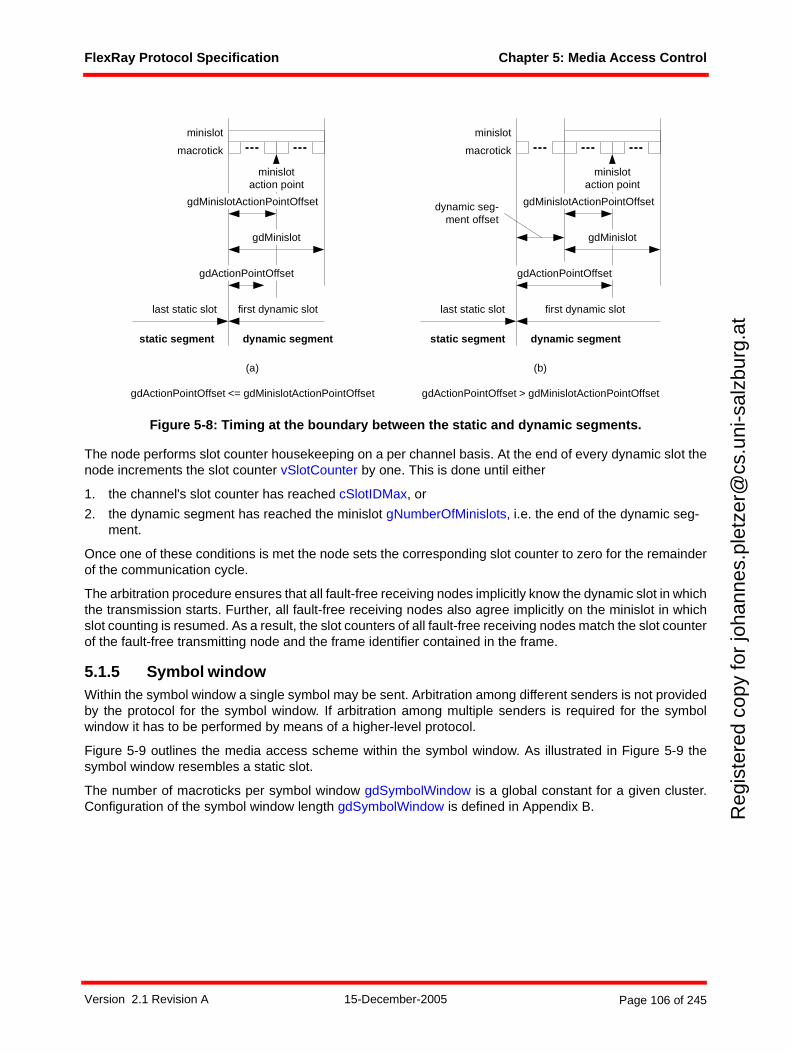
FlexRay Protocol Specification Chapter 5: Media Access Control
Reg
iste
red
copy
for
joha
nnes
.ple
tzer
@cs
.uni
-sal
zbur
g.at
Figure 5-8: Timing at the boundary between the static and dynamic segments.
The node performs slot counter housekeeping on a per channel basis. At the end of every dynamic slot thenode increments the slot counter vSlotCounter by one. This is done until either
1. the channel's slot counter has reached cSlotIDMax, or
2. the dynamic segment has reached the minislot gNumberOfMinislots, i.e. the end of the dynamic seg-ment.
Once one of these conditions is met the node sets the corresponding slot counter to zero for the remainderof the communication cycle.
The arbitration procedure ensures that all fault-free receiving nodes implicitly know the dynamic slot in whichthe transmission starts. Further, all fault-free receiving nodes also agree implicitly on the minislot in whichslot counting is resumed. As a result, the slot counters of all fault-free receiving nodes match the slot counterof the fault-free transmitting node and the frame identifier contained in the frame.
5.1.5 Symbol windowWithin the symbol window a single symbol may be sent. Arbitration among different senders is not providedby the protocol for the symbol window. If arbitration among multiple senders is required for the symbolwindow it has to be performed by means of a higher-level protocol.
Figure 5-9 outlines the media access scheme within the symbol window. As illustrated in Figure 5-9 thesymbol window resembles a static slot.
The number of macroticks per symbol window gdSymbolWindow is a global constant for a given cluster.Configuration of the symbol window length gdSymbolWindow is defined in Appendix B.
gdActionPointOffset
macrotick
minislot
gdMinislot
gdMinislotActionPointOffset
minislotaction point
first dynamic slotlast static slot
gdActionPointOffset
macrotick
minislot
gdMinislot
gdMinislotActionPointOffset
minislotaction point
first dynamic slotlast static slot
(b)
gdActionPointOffset > gdMinislotActionPointOffset
(a)
gdActionPointOffset <= gdMinislotActionPointOffset
static segment static segmentdynamic segment dynamic segment
dynamic seg-ment offset
Version 2.1 Revision A 15-December-2005 Page 106 of 245
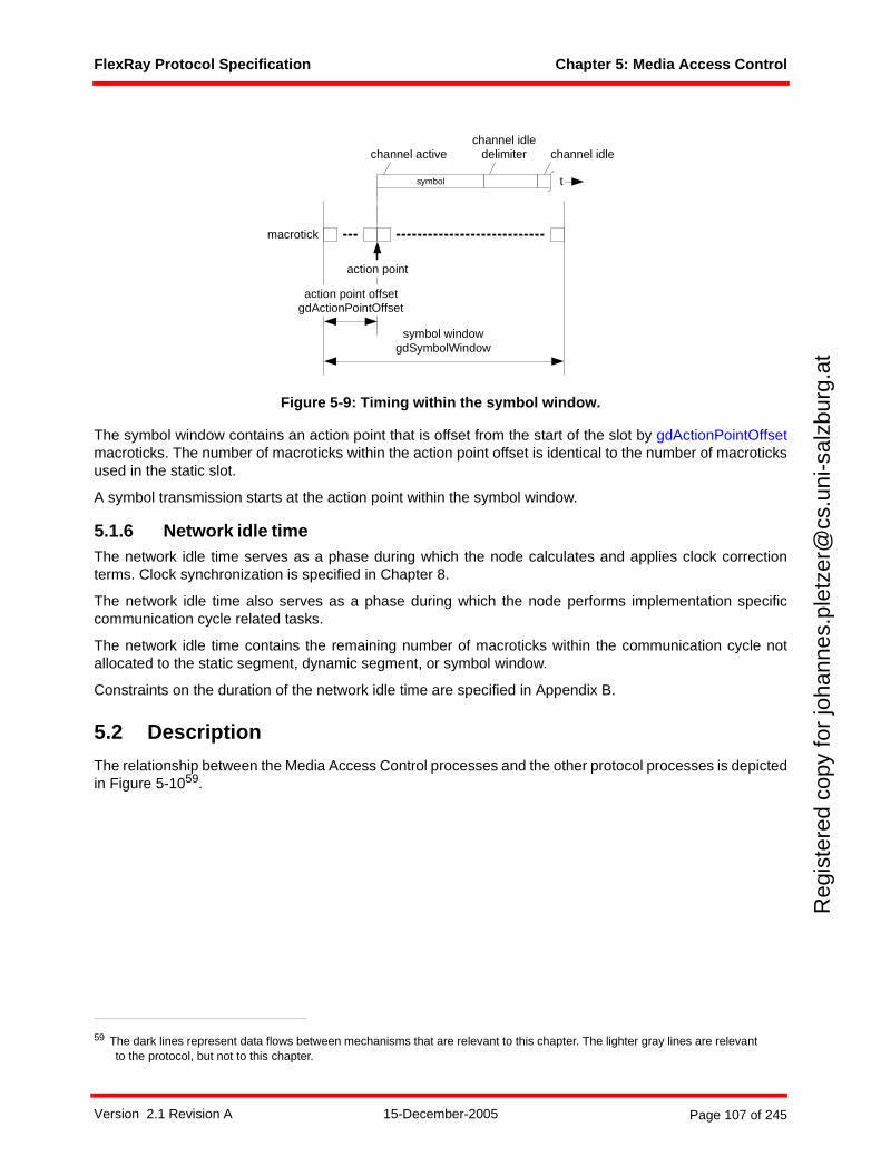
FlexRay Protocol Specification Chapter 5: Media Access Control
Reg
iste
red
copy
for
joha
nnes
.ple
tzer
@cs
.uni
-sal
zbur
g.at
Figure 5-9: Timing within the symbol window.
The symbol window contains an action point that is offset from the start of the slot by gdActionPointOffsetmacroticks. The number of macroticks within the action point offset is identical to the number of macroticksused in the static slot.
A symbol transmission starts at the action point within the symbol window.
5.1.6 Network idle timeThe network idle time serves as a phase during which the node calculates and applies clock correctionterms. Clock synchronization is specified in Chapter 8.
The network idle time also serves as a phase during which the node performs implementation specificcommunication cycle related tasks.
The network idle time contains the remaining number of macroticks within the communication cycle notallocated to the static segment, dynamic segment, or symbol window.
Constraints on the duration of the network idle time are specified in Appendix B.
5.2 Description
The relationship between the Media Access Control processes and the other protocol processes is depictedin Figure 5-1059.
59 The dark lines represent data flows between mechanisms that are relevant to this chapter. The lighter gray lines are relevant to the protocol, but not to this chapter.
symbol
macrotick
symbol windowgdSymbolWindow
action point offsetgdActionPointOffset
action point
channel idledelimiter channel idlechannel active
t
Version 2.1 Revision A 15-December-2005 Page 107 of 245
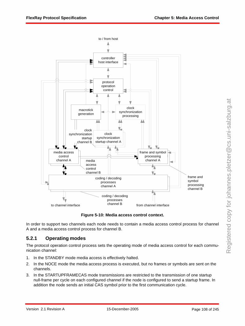
FlexRay Protocol Specification Chapter 5: Media Access Control
Reg
iste
red
copy
for
joha
nnes
.ple
tzer
@cs
.uni
-sal
zbur
g.at
Figure 5-10: Media access control context.
In order to support two channels each node needs to contain a media access control process for channelA and a media access control process for channel B.
5.2.1 Operating modesThe protocol operation control process sets the operating mode of media access control for each commu-nication channel:
1. In the STANDBY mode media access is effectively halted.
2. In the NOCE mode the media access process is executed, but no frames or symbols are sent on the channels.
3. In the STARTUPFRAMECAS mode transmissions are restricted to the transmission of one startup null-frame per cycle on each configured channel if the node is configured to send a startup frame. In addition the node sends an initial CAS symbol prior to the first communication cycle.
frame and symbolprocessing
media accesscontrol
clocksynchronization
startup
macrotickgeneration
clocksynchronization
processing
protocoloperation
control
controllerhost interface
coding / decodingprocesseschannel A
frame and symbolprocessingchannel A
media accesscontrol
channel A
clocksynchronization
startup channel A
to channel interface from channel interface
to / from host
mediaaccesscontrolchannel B
coding / decodingprocesseschannel B
frame andsymbolprocessingchannel B
clocksynchronization
startupchannel B
Version 2.1 Revision A 15-December-2005 Page 108 of 245
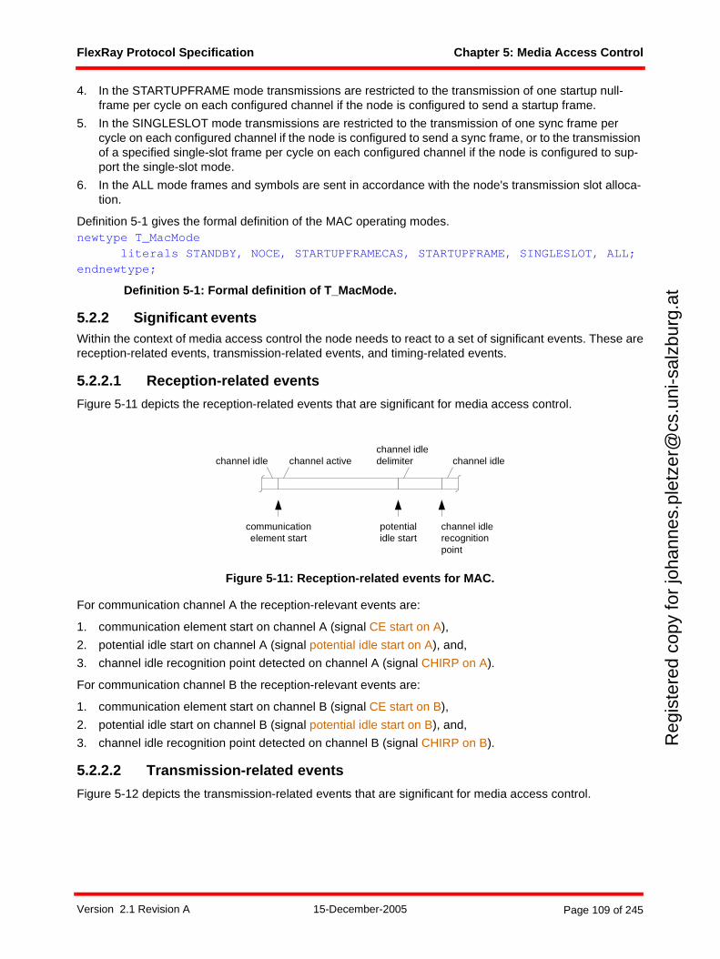
FlexRay Protocol Specification Chapter 5: Media Access Control
Reg
iste
red
copy
for
joha
nnes
.ple
tzer
@cs
.uni
-sal
zbur
g.at
4. In the STARTUPFRAME mode transmissions are restricted to the transmission of one startup null-frame per cycle on each configured channel if the node is configured to send a startup frame.
5. In the SINGLESLOT mode transmissions are restricted to the transmission of one sync frame per cycle on each configured channel if the node is configured to send a sync frame, or to the transmission of a specified single-slot frame per cycle on each configured channel if the node is configured to sup-port the single-slot mode.
6. In the ALL mode frames and symbols are sent in accordance with the node's transmission slot alloca-tion.
Definition 5-1 gives the formal definition of the MAC operating modes. newtype T_MacMode
literals STANDBY, NOCE, STARTUPFRAMECAS, STARTUPFRAME, SINGLESLOT, ALL;endnewtype;
Definition 5-1: Formal definition of T_MacMode.
5.2.2 Significant eventsWithin the context of media access control the node needs to react to a set of significant events. These arereception-related events, transmission-related events, and timing-related events.
5.2.2.1 Reception-related events
Figure 5-11 depicts the reception-related events that are significant for media access control.
Figure 5-11: Reception-related events for MAC.
For communication channel A the reception-relevant events are:
1. communication element start on channel A (signal CE start on A),
2. potential idle start on channel A (signal potential idle start on A), and,
3. channel idle recognition point detected on channel A (signal CHIRP on A).
For communication channel B the reception-relevant events are:
1. communication element start on channel B (signal CE start on B),
2. potential idle start on channel B (signal potential idle start on B), and,
3. channel idle recognition point detected on channel B (signal CHIRP on B).
5.2.2.2 Transmission-related events
Figure 5-12 depicts the transmission-related events that are significant for media access control.
channel activechannel idlechannel idledelimiter channel idle
channel idlerecognitionpoint
communicationelement start
potentialidle start
Version 2.1 Revision A 15-December-2005 Page 109 of 245
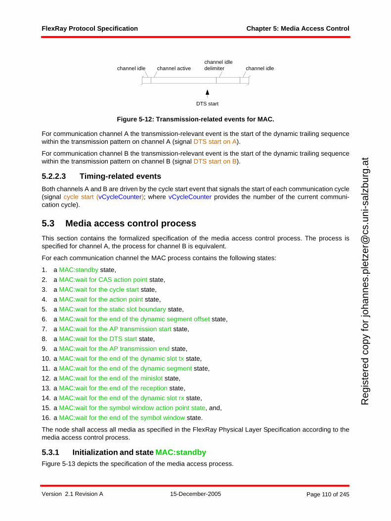
FlexRay Protocol Specification Chapter 5: Media Access Control
Reg
iste
red
copy
for
joha
nnes
.ple
tzer
@cs
.uni
-sal
zbur
g.at
Figure 5-12: Transmission-related events for MAC.
For communication channel A the transmission-relevant event is the start of the dynamic trailing sequencewithin the transmission pattern on channel A (signal DTS start on A).
For communication channel B the transmission-relevant event is the start of the dynamic trailing sequencewithin the transmission pattern on channel B (signal DTS start on B).
5.2.2.3 Timing-related events
Both channels A and B are driven by the cycle start event that signals the start of each communication cycle(signal cycle start (vCycleCounter); where vCycleCounter provides the number of the current communi-cation cycle).
5.3 Media access control process
This section contains the formalized specification of the media access control process. The process isspecified for channel A, the process for channel B is equivalent.
For each communication channel the MAC process contains the following states:
1. a MAC:standby state,
2. a MAC:wait for CAS action point state,
3. a MAC:wait for the cycle start state,
4. a MAC:wait for the action point state,
5. a MAC:wait for the static slot boundary state,
6. a MAC:wait for the end of the dynamic segment offset state,
7. a MAC:wait for the AP transmission start state,
8. a MAC:wait for the DTS start state,
9. a MAC:wait for the AP transmission end state,
10. a MAC:wait for the end of the dynamic slot tx state,
11. a MAC:wait for the end of the dynamic segment state,
12. a MAC:wait for the end of the minislot state,
13. a MAC:wait for the end of the reception state,
14. a MAC:wait for the end of the dynamic slot rx state,
15. a MAC:wait for the symbol window action point state, and,
16. a MAC:wait for the end of the symbol window state.
The node shall access all media as specified in the FlexRay Physical Layer Specification according to themedia access control process.
5.3.1 Initialization and state MAC:standby Figure 5-13 depicts the specification of the media access process.
channel activechannel idlechannel idledelimiter channel idle
DTS start
Version 2.1 Revision A 15-December-2005 Page 110 of 245
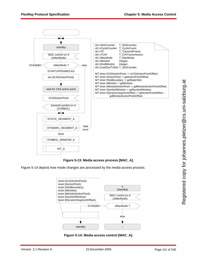
FlexRay Protocol Specification Chapter 5: Media Access Control
Reg
iste
red
copy
for
joha
nnes
.ple
tzer
@cs
.uni
-sal
zbur
g.at
Figure 5-13: Media access process [MAC_A].
Figure 5-14 depicts how mode changes are processed by the media access process.
Figure 5-14: Media access control [MAC_A].
standby
MAC control on A(zMacMode)
zMacMode ?STANDBY
wait for CAS action point
set (tCASActionPoint);
transmit symbol on A(SYMBOL)
STARTUPFRAMECAS
else
tCASActionPoint
STATIC_SEGMENT_A
DYNAMIC_SEGMENT_A
SYMBOL_WINDOW_A
NIT_A
done
dcl vSlotCounter T_SlotCounter;dcl vCycleCounter T_CycleCount;dcl vTF T_TransmitFrame;dcl vTCHI T_CHITransmission;dcl zMacMode T_MacMode;dcl zMinislot Integer;dcl zEndMinislot Integer;dcl zLastDynTxSlot T_SlotCounter;
MT timer tCASActionPoint := cCASActionPointOffset;MT timer tActionPoint := gdActionPointOffset;MT timer tSlotBoundary := gdStaticSlot;MT timer tMinislot := gdMinislot;MT timer tMinislotActionPoint := gdMinislotActionPointOffset;MT timer tSymbolWindow := gdSymbolWindow;MT timer tDynamicSegmentOffset := gdActionPointOffset -
gdMinislotActionPointOffset;
fatalerror
*(standby)
MAC control on A(zMacMode)
zMacMode ?
-standby
STANDBY
else
reset (tCASActionPoint);reset (tActionPoint);reset (tSlotBoundary);reset (tMinislot);reset (tMinislotActionPoint);reset (tSymbolWindow);reset (tDynamicSegmentOffset);
Version 2.1 Revision A 15-December-2005 Page 111 of 245
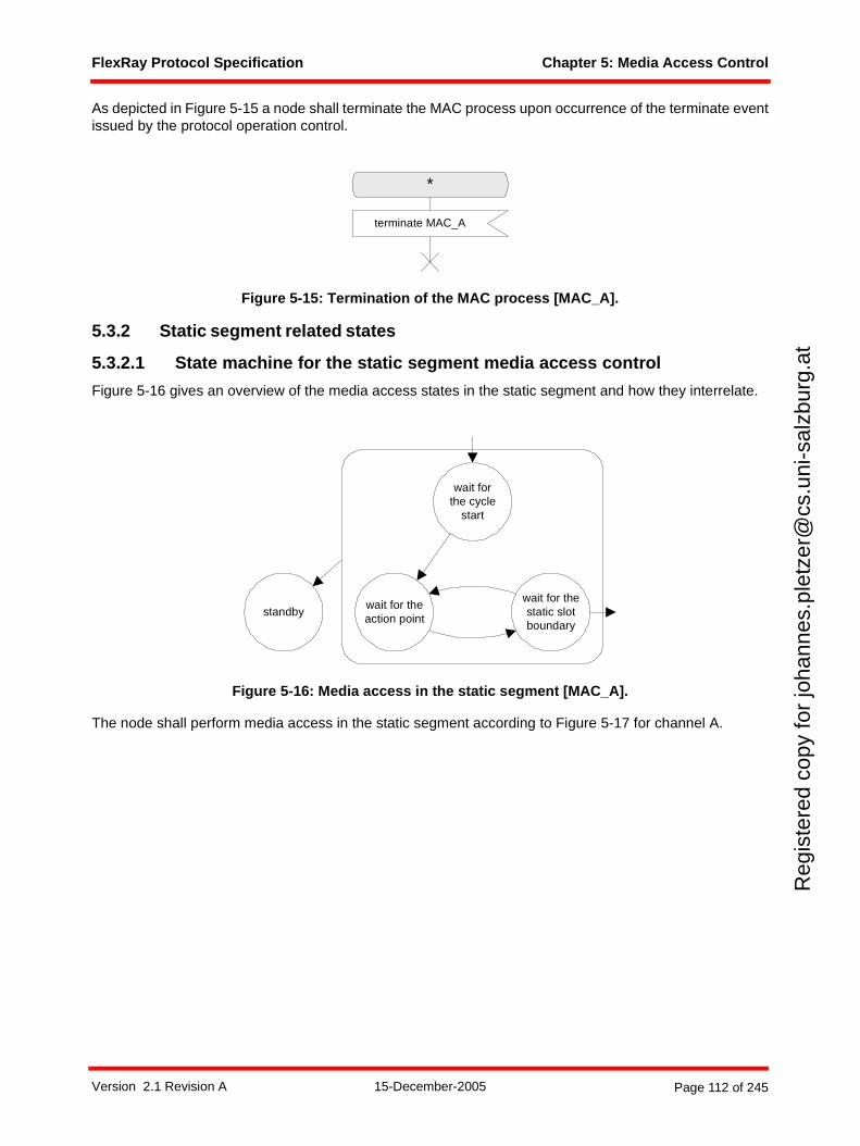
FlexRay Protocol Specification Chapter 5: Media Access Control
Reg
iste
red
copy
for
joha
nnes
.ple
tzer
@cs
.uni
-sal
zbur
g.at
As depicted in Figure 5-15 a node shall terminate the MAC process upon occurrence of the terminate eventissued by the protocol operation control.
Figure 5-15: Termination of the MAC process [MAC_A].
5.3.2 Static segment related states
5.3.2.1 State machine for the static segment media access control
Figure 5-16 gives an overview of the media access states in the static segment and how they interrelate.
Figure 5-16: Media access in the static segment [MAC_A].
The node shall perform media access in the static segment according to Figure 5-17 for channel A.
*
terminate MAC_A
wait forthe cycle
start
wait for thestatic slotboundary
wait for theaction point
standby
Version 2.1 Revision A 15-December-2005 Page 112 of 245
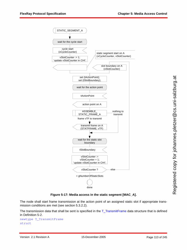
FlexRay Protocol Specification Chapter 5: Media Access Control
Reg
iste
red
copy
for
joha
nnes
.ple
tzer
@cs
.uni
-sal
zbur
g.at
Figure 5-17: Media access in the static segment [MAC_A].
The node shall start frame transmission at the action point of an assigned static slot if appropriate trans-mission conditions are met (see section 5.3.2.2).
The transmission data that shall be sent is specified in the T_TransmitFrame data structure that is definedin Definition 5-2. newtype T_TransmitFrame struct
wait for the cycle start
cycle start(vCycleCounter)
vSlotCounter := 1;’update vSlotCounter in CHI’;
static segment start on A(vCycleCounter, vSlotCounter)
wait for the static slotboundary
nothing totransmit
wait for the action point
transmit frame on A(STATFRAME, vTF)
set (tActionPoint);set (tSlotBoundary);
tActionPoint
tSlotBoundary
vSlotCounter ?
vSlotCounter :=vSlotCounter + 1;
’update vSlotCounter in CHI’;
else
> gNumberOfStaticSlots
slot boundary on A(vSlotCounter)
STATIC_SEGMENT_A
done
frame vTF to transmit
ASSEMBLE_STATIC_FRAME_A
action point on A
Version 2.1 Revision A 15-December-2005 Page 113 of 245
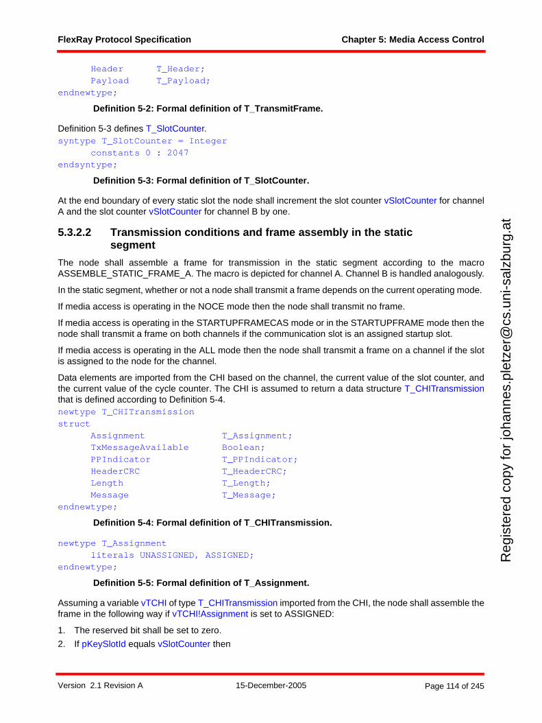
FlexRay Protocol Specification Chapter 5: Media Access Control
Reg
iste
red
copy
for
joha
nnes
.ple
tzer
@cs
.uni
-sal
zbur
g.at
Header T_Header;Payload T_Payload;
endnewtype;
Definition 5-2: Formal definition of T_TransmitFrame.
Definition 5-3 defines T_SlotCounter.syntype T_SlotCounter = Integer
constants 0 : 2047 endsyntype;
Definition 5-3: Formal definition of T_SlotCounter.
At the end boundary of every static slot the node shall increment the slot counter vSlotCounter for channelA and the slot counter vSlotCounter for channel B by one.
5.3.2.2 Transmission conditions and frame assembly in the static segment
The node shall assemble a frame for transmission in the static segment according to the macroASSEMBLE_STATIC_FRAME_A. The macro is depicted for channel A. Channel B is handled analogously.
In the static segment, whether or not a node shall transmit a frame depends on the current operating mode.
If media access is operating in the NOCE mode then the node shall transmit no frame.
If media access is operating in the STARTUPFRAMECAS mode or in the STARTUPFRAME mode then thenode shall transmit a frame on both channels if the communication slot is an assigned startup slot.
If media access is operating in the ALL mode then the node shall transmit a frame on a channel if the slotis assigned to the node for the channel.
Data elements are imported from the CHI based on the channel, the current value of the slot counter, andthe current value of the cycle counter. The CHI is assumed to return a data structure T_CHITransmissionthat is defined according to Definition 5-4.newtype T_CHITransmission struct
Assignment T_Assignment;TxMessageAvailable Boolean;PPIndicator T_PPIndicator;HeaderCRC T_HeaderCRC;Length T_Length;Message T_Message;
endnewtype;
Definition 5-4: Formal definition of T_CHITransmission.
newtype T_Assignmentliterals UNASSIGNED, ASSIGNED;
endnewtype;
Definition 5-5: Formal definition of T_Assignment.
Assuming a variable vTCHI of type T_CHITransmission imported from the CHI, the node shall assemble theframe in the following way if vTCHI!Assignment is set to ASSIGNED:
1. The reserved bit shall be set to zero.
2. If pKeySlotId equals vSlotCounter then
Version 2.1 Revision A 15-December-2005 Page 114 of 245

FlexRay Protocol Specification Chapter 5: Media Access Control
Reg
iste
red
copy
for
joha
nnes
.ple
tzer
@cs
.uni
-sal
zbur
g.at
a. the startup frame indicator shall be set in accordance with pKeySlotUsedForStartup, and
b. the sync frame indicator shall be set in accordance with pKeySlotUsedForSync.
else
c. the startup frame indicator shall be set to zero, and
d. the sync frame indicator shall be set to zero.
3. The frame ID field shall be set to the current value of the slot counter vSlotCounter.
4. The length field shall be set to gPayloadLengthStatic.
5. The header CRC shall be set to the value vTCHI!HeaderCRC retrieved from the CHI.
6. The cycle count field shall be set to the current value of the cycle counter vCycleCounter.
7. If the host has data available (vTCHI!TxMessageAvailable set to true) then
a. the null frame indicator shall be set to one, and
b. the payload preamble indicator shall be set to the value vTCHI!PPIndicator imported from the CHI,and
c. vTCHI!Length number of two-byte payload words shall be copied from vTCHI!Message tovTF!Payload, and
d. any remaining payload data words shall be set to the padding pattern 0x00
else if the host has no data available (vTCHI!TxMessageAvailable set to false) then
e. the null frame indicator shall be set to zero, and
f. the payload preamble indicator shall be set to zero, and
g. all payload data shall be set to the padding pattern 0x00.
Version 2.1 Revision A 15-December-2005 Page 115 of 245
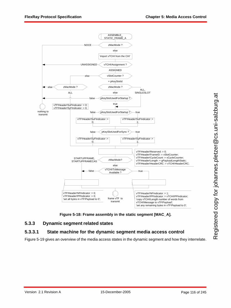
FlexRay Protocol Specification Chapter 5: Media Access Control
Reg
iste
red
copy
for
joha
nnes
.ple
tzer
@cs
.uni
-sal
zbur
g.at
Figure 5-18: Frame assembly in the static segment [MAC_A].
5.3.3 Dynamic segment related states
5.3.3.1 State machine for the dynamic segment media access control
Figure 5-19 gives an overview of the media access states in the dynamic segment and how they interrelate.
UNASSIGNED
else
vTCHI!TxMessageAvailable ?
truefalse
vTF!Header!NFIndicator := 1;vTF!Header!PPIndicator := vTCHI!PPIndicator;'copy vTCHI!Length number of words fromvTCHI!Message to vTF!Payload';'set any remaining bytes in vTF!Payload to 0';
else
vTF!Header!Reserved := 0;vTF!Header!FrameID := vSlotCounter;vTF!Header!CycleCount := vCycleCounter;vTF!Header!Length := gPayloadLengthStatic;vTF!Header!HeaderCRC := vTCHI!HeaderCRC;
nothing totransmit
frame vTF totransmit
zMacMode ?
ALL
NOCE
ASSEMBLE_STATIC_FRAME_A
'import vTCHI from the CHI’
vTF!Header!NFIndicator := 0;vTF!Header!PPIndicator := 0;'set all bytes in vTF!Payload to 0';
zMacMode ?
ASSIGNED
false
zMacMode?STARTUPFRAME,
STARTUPFRAMECAS
else
vTCHI!Assignment ?
vSlotCounter ?else
zMacMode ?
= pKeySlotId
pKeySlotUsedForStartup ?
else
true
ALL,SINGLESLOT
vTF!Header!SuFIndicator := 0;vTF!Header!SyFIndicator := 0;
pKeySlotUsedForStartup ?
vTF!Header!SuFIndicator :=0;
false
vTF!Header!SuFIndicator :=1;
true
pKeySlotUsedForSync ?
vTF!Header!SyFIndicator :=0;
false
vTF!Header!SyFIndicator :=1;
true
Version 2.1 Revision A 15-December-2005 Page 116 of 245
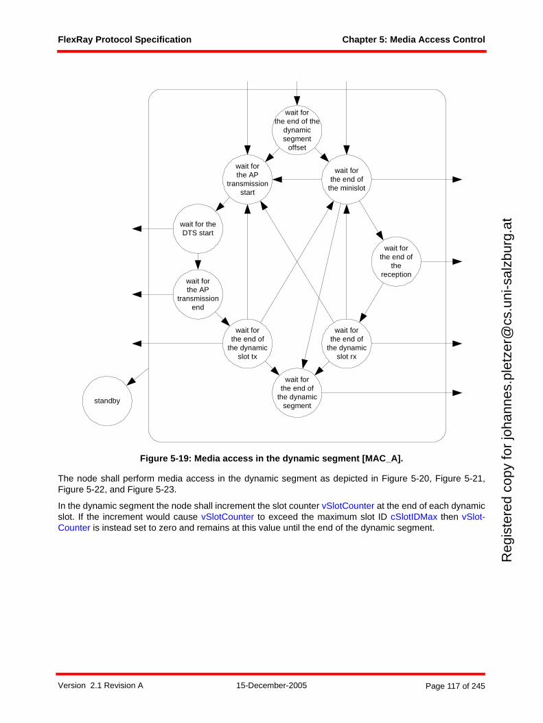
FlexRay Protocol Specification Chapter 5: Media Access Control
Reg
iste
red
copy
for
joha
nnes
.ple
tzer
@cs
.uni
-sal
zbur
g.at
Figure 5-19: Media access in the dynamic segment [MAC_A].
The node shall perform media access in the dynamic segment as depicted in Figure 5-20, Figure 5-21,Figure 5-22, and Figure 5-23.
In the dynamic segment the node shall increment the slot counter vSlotCounter at the end of each dynamicslot. If the increment would cause vSlotCounter to exceed the maximum slot ID cSlotIDMax then vSlot-Counter is instead set to zero and remains at this value until the end of the dynamic segment.
wait forthe AP
transmissionstart
wait forthe end of
the minislot
wait for theDTS start
wait forthe AP
transmissionend
wait forthe end of
thereception
wait forthe end of the
dynamicsegment
offset
wait forthe end of
the dynamicslot rx
wait forthe end of
the dynamicsegment
standby
wait forthe end of
the dynamicslot tx
Version 2.1 Revision A 15-December-2005 Page 117 of 245
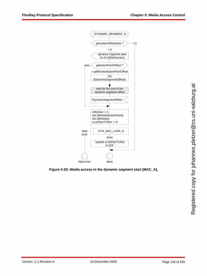
FlexRay Protocol Specification Chapter 5: Media Access Control
Reg
iste
red
copy
for
joha
nnes
.ple
tzer
@cs
.uni
-sal
zbur
g.at
Figure 5-20: Media access in the dynamic segment start [MAC_A].
gNumberOfMinislots ? = 0
dynamic segment starton A (vSlotCounter)
zMinislot := 1;set (tMinislotActionPoint);set (tMinislot);zLastDynTxSlot := 0;
gdActionPointOffset ?
set(tDynamicSegmentOffset);
> 0
wait for the end of thedynamic segment offset
tDynamicSegmentOffset
> gdMinislotActionPointOffset
else
DYNAMIC_SEGMENT_A
DYN_SEG_LOOP_A
’update zLastDynTxSlotin CHI’
done
done
fatal error
fatalerror
Version 2.1 Revision A 15-December-2005 Page 118 of 245
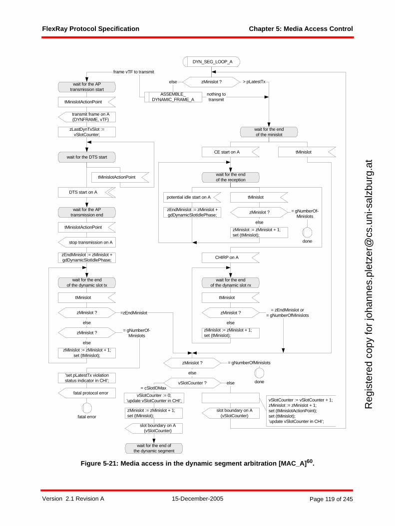
FlexRay Protocol Specification Chapter 5: Media Access Control
Reg
iste
red
copy
for
joha
nnes
.ple
tzer
@cs
.uni
-sal
zbur
g.at
Figure 5-21: Media access in the dynamic segment arbitration [MAC_A]60.
zMinislot ?
ASSEMBLE_DYNAMIC_FRAME_A
wait for the APtransmission start
else
tMinislotActionPoint
wait for the APtransmission end
wait for the DTS start
zEndMinislot := zMinislot +gdDynamicSlotIdlePhase;
tMinislotActionPoint
stop transmission on A
transmit frame on A(DYNFRAME, vTF)
wait for the endof the dynamic slot tx
tMinislot
zMinislot ?
= gNumberOf-Minislots
slot boundary on A(vSlotCounter)
slot boundary on A(vSlotCounter)
vSlotCounter := 0;’update vSlotCounter in CHI’;
= cSlotIDMax
wait for the end ofthe dynamic segment
wait for the endof the minislot
wait for the endof the reception
zEndMinislot := zMinislot +gdDynamicSlotIdlePhase;
potential idle start on A
CE start on A
CHIRP on A
zMinislot := zMinislot + 1;set (tMinislot);
vSlotCounter := vSlotCounter + 1;zMinislot := zMinislot + 1;set (tMinislotActionPoint);set (tMinislot);’update vSlotCounter in CHI’;
tMinislot
tMinislot
zMinislot := zMinislot + 1;set (tMinislot);
zMinislot ?
else
else
else
= zEndMinislot or= gNumberOfMinislots
zMinislot := zMinislot + 1;set (tMinislot);
> pLatestTx
nothing totransmit
frame vTF to transmit
done
= gNumberOf-Minislots
zMinislot ?
else
=zEndMinislot
wait for the endof the dynamic slot rx
tMinislot
zMinislot ?
zMinislot := zMinislot + 1;set (tMinislot);
else
zMinislot ? = gNumberOfMinislots
done
else'set pLatestTx violationstatus indicator in CHI';
fatal error
fatal protocol error
zLastDynTxSlot :=vSlotCounter;
DYN_SEG_LOOP_A
DTS start on A
tMinislotActionPoint
vSlotCounter ?
Version 2.1 Revision A 15-December-2005 Page 119 of 245
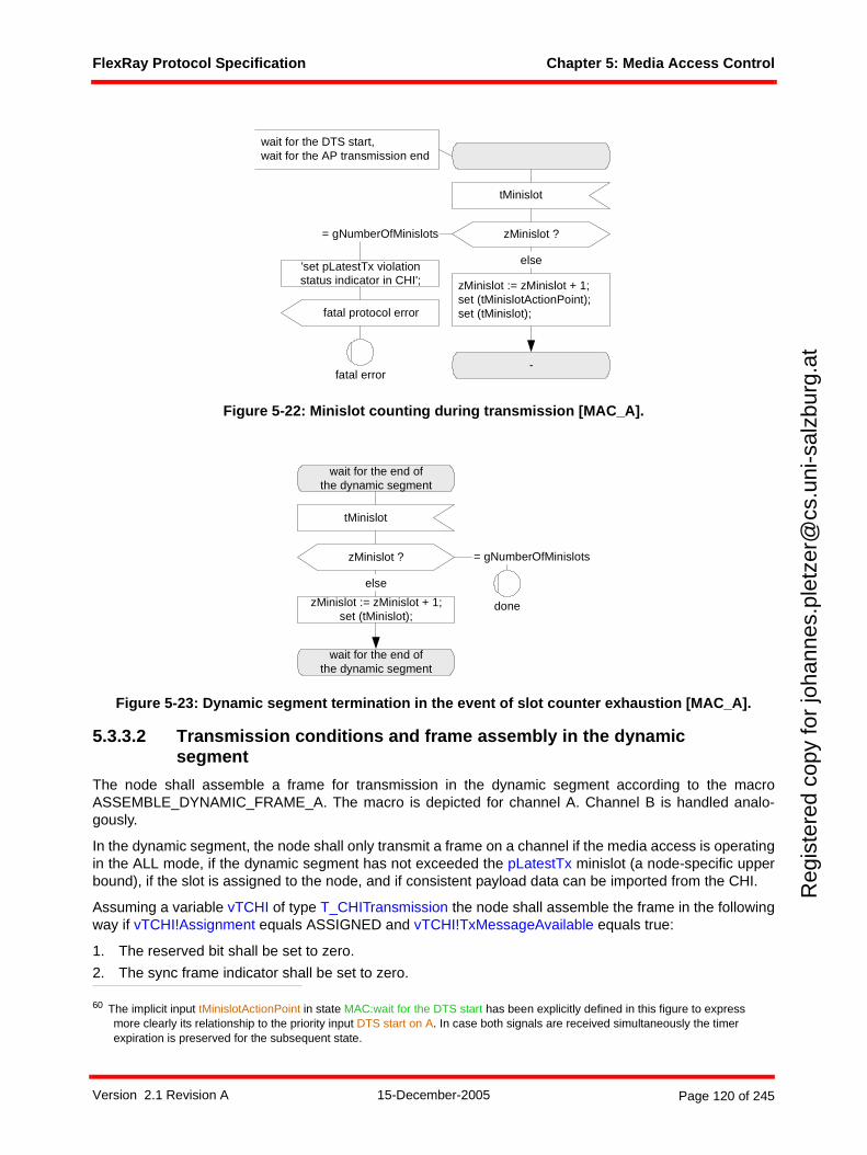
FlexRay Protocol Specification Chapter 5: Media Access Control
Reg
iste
red
copy
for
joha
nnes
.ple
tzer
@cs
.uni
-sal
zbur
g.at
Figure 5-22: Minislot counting during transmission [MAC_A].
Figure 5-23: Dynamic segment termination in the event of slot counter exhaustion [MAC_A].
5.3.3.2 Transmission conditions and frame assembly in the dynamic segment
The node shall assemble a frame for transmission in the dynamic segment according to the macroASSEMBLE_DYNAMIC_FRAME_A. The macro is depicted for channel A. Channel B is handled analo-gously.
In the dynamic segment, the node shall only transmit a frame on a channel if the media access is operatingin the ALL mode, if the dynamic segment has not exceeded the pLatestTx minislot (a node-specific upperbound), if the slot is assigned to the node, and if consistent payload data can be imported from the CHI.
Assuming a variable vTCHI of type T_CHITransmission the node shall assemble the frame in the followingway if vTCHI!Assignment equals ASSIGNED and vTCHI!TxMessageAvailable equals true:
1. The reserved bit shall be set to zero.
2. The sync frame indicator shall be set to zero.
60 The implicit input tMinislotActionPoint in state MAC:wait for the DTS start has been explicitly defined in this figure to express more clearly its relationship to the priority input DTS start on A. In case both signals are received simultaneously the timer expiration is preserved for the subsequent state.
tMinislot
zMinislot := zMinislot + 1;set (tMinislotActionPoint);set (tMinislot);
zMinislot ?
else
fatal protocol error
= gNumberOfMinislots
-
wait for the DTS start,wait for the AP transmission end
'set pLatestTx violationstatus indicator in CHI';
fatal error
wait for the end ofthe dynamic segment
tMinislot
zMinislot := zMinislot + 1;set (tMinislot);
zMinislot ?
else
= gNumberOfMinislots
wait for the end ofthe dynamic segment
done
Version 2.1 Revision A 15-December-2005 Page 120 of 245
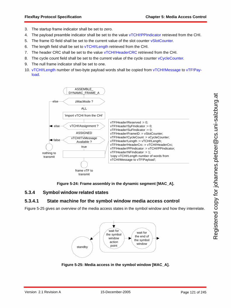
FlexRay Protocol Specification Chapter 5: Media Access Control
Reg
iste
red
copy
for
joha
nnes
.ple
tzer
@cs
.uni
-sal
zbur
g.at
3. The startup frame indicator shall be set to zero.
4. The payload preamble indicator shall be set to the value vTCHI!PPIndicator retrieved from the CHI.
5. The frame ID field shall be set to the current value of the slot counter vSlotCounter.
6. The length field shall be set to vTCHI!Length retrieved from the CHI.
7. The header CRC shall be set to the value vTCHI!HeaderCRC retrieved from the CHI.
8. The cycle count field shall be set to the current value of the cycle counter vCycleCounter.
9. The null frame indicator shall be set to one.
10. vTCHI!Length number of two-byte payload words shall be copied from vTCHI!Message to vTF!Pay-load.
Figure 5-24: Frame assembly in the dynamic segment [MAC_A].
5.3.4 Symbol window related states
5.3.4.1 State machine for the symbol window media access control
Figure 5-25 gives an overview of the media access states in the symbol window and how they interrelate.
Figure 5-25: Media access in the symbol window [MAC_A].
vTCHI!TxMessageAvailable ?false
vTF!Header!Reserved := 0;vTF!Header!SyFIndicator := 0;vTF!Header!SuFIndicator := 0;vTF!Header!FrameID := vSlotCounter;vTF!Header!CycleCount := vCycleCounter;vTF!Header!Length := vTCHI!Length;vTF!Header!HeaderCrc := vTCHI!HeaderCrc;vTF!Header!PPIndicator := vTCHI!PPIndicator;vTF!Header!NFIndicator := 1;'copy vTCHI!Length number of words fromvTCHI!Message to vTF!Payload';
zMacMode ?else
ALL
true
ASSEMBLE_DYNAMIC_FRAME_A
nothing totransmit
frame vTF totransmit
'import vTCHI from the CHI’
ASSIGNED
vTCHI!Assignment ?else
wait forthe end ofthe symbol
window
wait forthe symbol
windowactionpointstandby
Version 2.1 Revision A 15-December-2005 Page 121 of 245
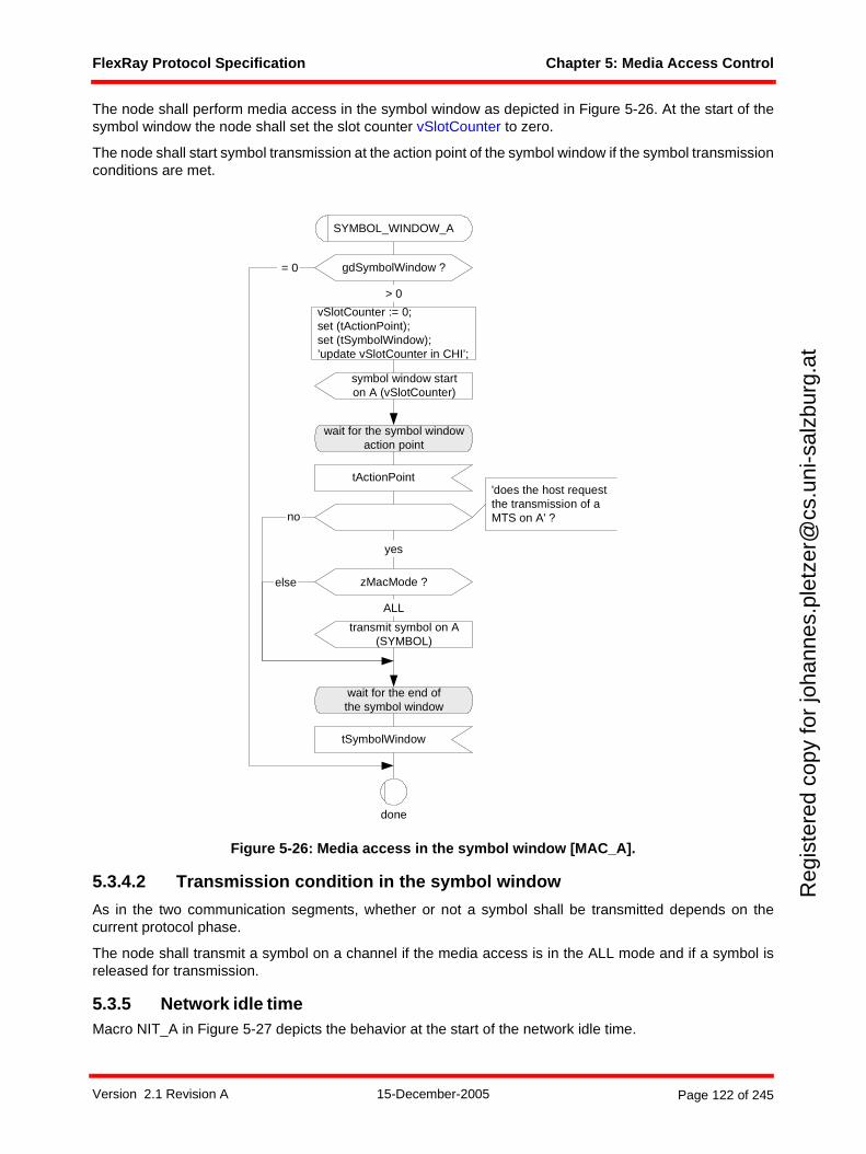
FlexRay Protocol Specification Chapter 5: Media Access Control
Reg
iste
red
copy
for
joha
nnes
.ple
tzer
@cs
.uni
-sal
zbur
g.at
The node shall perform media access in the symbol window as depicted in Figure 5-26. At the start of thesymbol window the node shall set the slot counter vSlotCounter to zero.
The node shall start symbol transmission at the action point of the symbol window if the symbol transmissionconditions are met.
Figure 5-26: Media access in the symbol window [MAC_A].
5.3.4.2 Transmission condition in the symbol window
As in the two communication segments, whether or not a symbol shall be transmitted depends on thecurrent protocol phase.
The node shall transmit a symbol on a channel if the media access is in the ALL mode and if a symbol isreleased for transmission.
5.3.5 Network idle timeMacro NIT_A in Figure 5-27 depicts the behavior at the start of the network idle time.
no
yes
zMacMode ?
transmit symbol on A(SYMBOL)
ALL
else
wait for the end ofthe symbol window
tSymbolWindow
gdSymbolWindow ? = 0
> 0
vSlotCounter := 0;set (tActionPoint);set (tSymbolWindow);’update vSlotCounter in CHI’;
symbol window starton A (vSlotCounter)
done
SYMBOL_WINDOW_A
wait for the symbol windowaction point
tActionPoint'does the host requestthe transmission of aMTS on A' ?
Version 2.1 Revision A 15-December-2005 Page 122 of 245
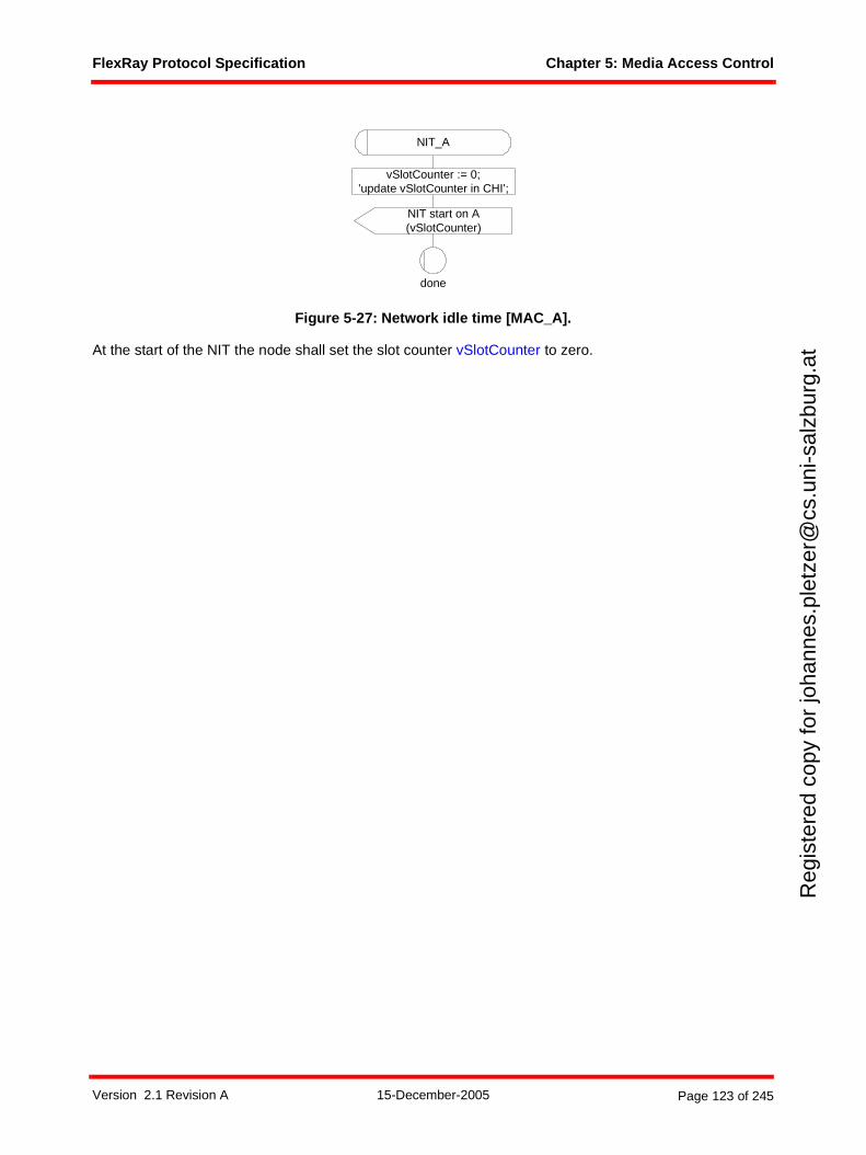
FlexRay Protocol Specification Chapter 5: Media Access Control
Reg
iste
red
copy
for
joha
nnes
.ple
tzer
@cs
.uni
-sal
zbur
g.at
Figure 5-27: Network idle time [MAC_A].
At the start of the NIT the node shall set the slot counter vSlotCounter to zero.
NIT start on A(vSlotCounter)
vSlotCounter := 0;’update vSlotCounter in CHI’;
NIT_A
done
Version 2.1 Revision A 15-December-2005 Page 123 of 245
FlexRay Protocol Specification Chapter 6: Frame and Symbol Processing
Reg
iste
red
copy
for
joha
nnes
.ple
tzer
@cs
.uni
-sal
zbur
g.at
Chapter 6Frame and Symbol Processing
This chapter defines how the node shall perform frame and symbol processing.
6.1 Principles
Frame and symbol processing (FSP) is the main processing layer between frame and symbol decoding,which is specified in Chapter 3, and the controller host interface, which is specified in Chapter 9.
Frame and symbol processing checks the correct timing of frames and symbols with respect to the TDMAscheme, applies further syntactical tests to received frames, and checks the semantic correctness ofreceived frames.
6.2 Description
The relationship between the Frame and Symbol Processing processes and the other protocol processesis depicted in Figure 6-161.
61 The dark lines represent data flows between mechanisms that are relevant to this chapter. The lighter gray lines are relevant to the protocol, but not to this chapter.
Version 2.1 Revision A 15-December-2005 Page 124 of 245
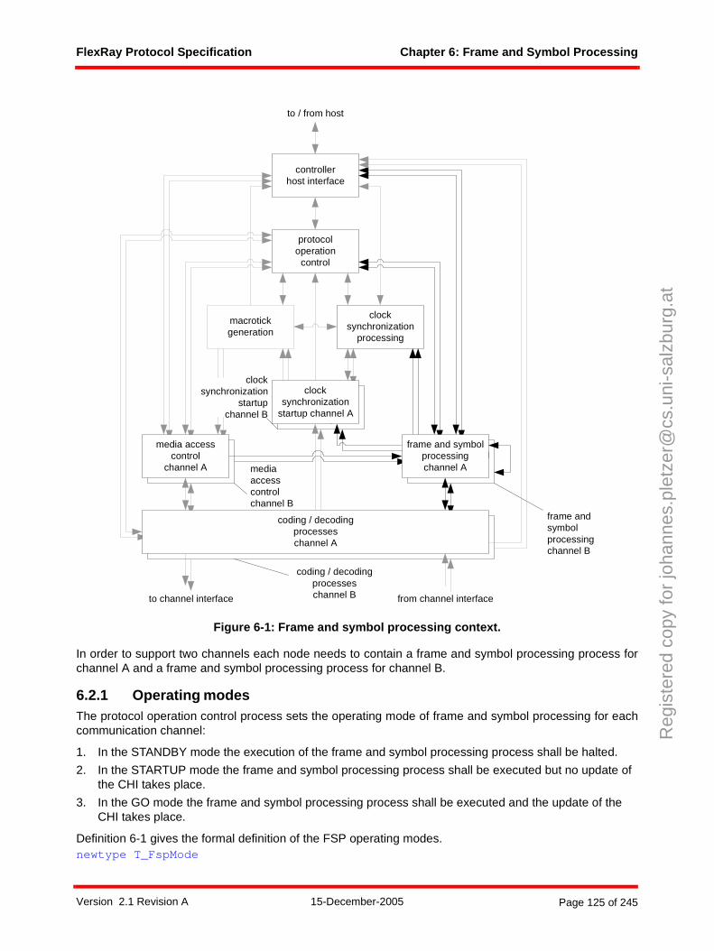
FlexRay Protocol Specification Chapter 6: Frame and Symbol Processing
Reg
iste
red
copy
for
joha
nnes
.ple
tzer
@cs
.uni
-sal
zbur
g.at
Figure 6-1: Frame and symbol processing context.
In order to support two channels each node needs to contain a frame and symbol processing process forchannel A and a frame and symbol processing process for channel B.
6.2.1 Operating modesThe protocol operation control process sets the operating mode of frame and symbol processing for eachcommunication channel:
1. In the STANDBY mode the execution of the frame and symbol processing process shall be halted.
2. In the STARTUP mode the frame and symbol processing process shall be executed but no update of the CHI takes place.
3. In the GO mode the frame and symbol processing process shall be executed and the update of the CHI takes place.
Definition 6-1 gives the formal definition of the FSP operating modes.newtype T_FspMode
frame and symbolprocessing
media accesscontrol
clocksynchronization
startup
macrotickgeneration
clocksynchronization
processing
protocoloperation
control
controllerhost interface
coding / decodingprocesseschannel A
frame and symbolprocessingchannel A
media accesscontrol
channel A
clocksynchronization
startup channel A
to channel interface from channel interface
to / from host
mediaaccesscontrolchannel B
coding / decodingprocesseschannel B
frame andsymbolprocessingchannel B
clocksynchronization
startupchannel B
Version 2.1 Revision A 15-December-2005 Page 125 of 245
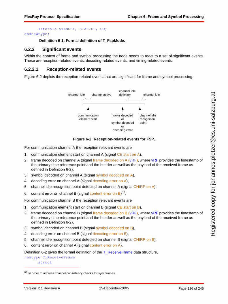
FlexRay Protocol Specification Chapter 6: Frame and Symbol Processing
Reg
iste
red
copy
for
joha
nnes
.ple
tzer
@cs
.uni
-sal
zbur
g.at
literals STANDBY, STARTUP, GO;endnewtype;
Definition 6-1: Formal definition of T_FspMode.
6.2.2 Significant eventsWithin the context of frame and symbol processing the node needs to react to a set of significant events.These are reception-related events, decoding-related events, and timing-related events.
6.2.2.1 Reception-related events
Figure 6-2 depicts the reception-related events that are significant for frame and symbol processing.
Figure 6-2: Reception-related events for FSP.
For communication channel A the reception relevant events are
1. communication element start on channel A (signal CE start on A),
2. frame decoded on channel A (signal frame decoded on A (vRF), where vRF provides the timestamp of the primary time reference point and the header as well as the payload of the received frame as defined in Definition 6-2),
3. symbol decoded on channel A (signal symbol decoded on A),
4. decoding error on channel A (signal decoding error on A),
5. channel idle recognition point detected on channel A (signal CHIRP on A),
6. content error on channel B (signal content error on B)62.
For communication channel B the reception relevant events are
1. communication element start on channel B (signal CE start on B),
2. frame decoded on channel B (signal frame decoded on B (vRF), where vRF provides the timestamp of the primary time reference point and the header as well as the payload of the received frame as defined in Definition 6-2),
3. symbol decoded on channel B (signal symbol decoded on B),
4. decoding error on channel B (signal decoding error on B),
5. channel idle recognition point detected on channel B (signal CHIRP on B),
6. content error on channel A (signal content error on A).
Definition 6-2 gives the formal definition of the T_ReceiveFrame data structure.newtype T_ReceiveFrame
struct
62 In order to address channel consistency checks for sync frames.
channel idlerecognitionpoint
communicationelement start
frame decodedor
symbol decodedor
decoding error
channel activechannel idlechannel idledelimiter channel idle
Version 2.1 Revision A 15-December-2005 Page 126 of 245
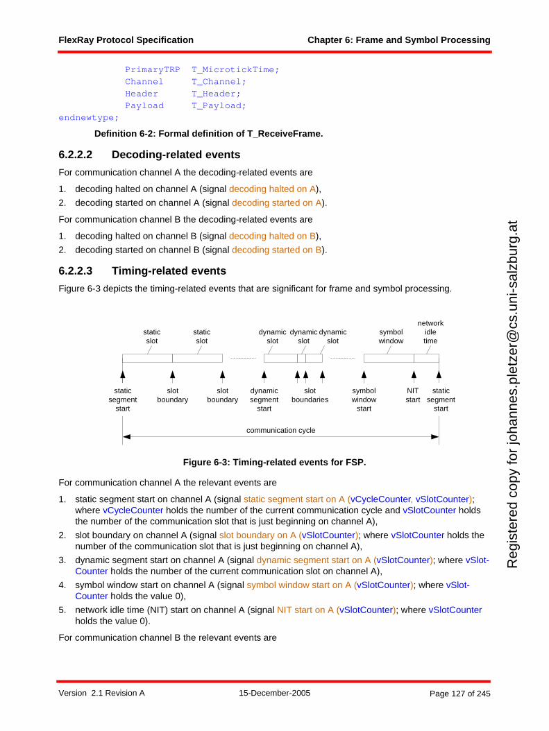
FlexRay Protocol Specification Chapter 6: Frame and Symbol Processing
Reg
iste
red
copy
for
joha
nnes
.ple
tzer
@cs
.uni
-sal
zbur
g.at
PrimaryTRP T_MicrotickTime;Channel T_Channel;Header T_Header;Payload T_Payload;
endnewtype;
Definition 6-2: Formal definition of T_ReceiveFrame.
6.2.2.2 Decoding-related events
For communication channel A the decoding-related events are
1. decoding halted on channel A (signal decoding halted on A),
2. decoding started on channel A (signal decoding started on A).
For communication channel B the decoding-related events are
1. decoding halted on channel B (signal decoding halted on B),
2. decoding started on channel B (signal decoding started on B).
6.2.2.3 Timing-related events
Figure 6-3 depicts the timing-related events that are significant for frame and symbol processing.
Figure 6-3: Timing-related events for FSP.
For communication channel A the relevant events are
1. static segment start on channel A (signal static segment start on A (vCycleCounter, vSlotCounter); where vCycleCounter holds the number of the current communication cycle and vSlotCounter holds the number of the communication slot that is just beginning on channel A),
2. slot boundary on channel A (signal slot boundary on A (vSlotCounter); where vSlotCounter holds the number of the communication slot that is just beginning on channel A),
3. dynamic segment start on channel A (signal dynamic segment start on A (vSlotCounter); where vSlot-Counter holds the number of the current communication slot on channel A),
4. symbol window start on channel A (signal symbol window start on A (vSlotCounter); where vSlot-Counter holds the value 0),
5. network idle time (NIT) start on channel A (signal NIT start on A (vSlotCounter); where vSlotCounter holds the value 0).
For communication channel B the relevant events are
staticsegment
start
staticsegment
start
slotboundary
dynamicsegment
start
slotboundaries
symbolwindow
start
communication cycle
slotboundary
staticslot
staticslot
dynamicslot
dynamicslot
dynamicslot
symbolwindow
networkidletime
NITstart
Version 2.1 Revision A 15-December-2005 Page 127 of 245
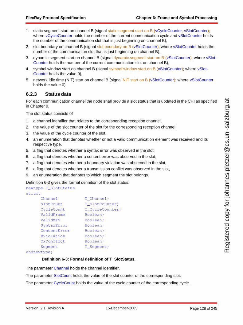
FlexRay Protocol Specification Chapter 6: Frame and Symbol Processing
Reg
iste
red
copy
for
joha
nnes
.ple
tzer
@cs
.uni
-sal
zbur
g.at
1. static segment start on channel B (signal static segment start on B (vCycleCounter, vSlotCounter); where vCycleCounter holds the number of the current communication cycle and vSlotCounter holds the number of the communication slot that is just beginning on channel B),
2. slot boundary on channel B (signal slot boundary on B (vSlotCounter); where vSlotCounter holds the number of the communication slot that is just beginning on channel B),
3. dynamic segment start on channel B (signal dynamic segment start on B (vSlotCounter); where vSlot-Counter holds the number of the current communication slot on channel B),
4. symbol window start on channel B (signal symbol window start on B (vSlotCounter); where vSlot-Counter holds the value 0),
5. network idle time (NIT) start on channel B (signal NIT start on B (vSlotCounter); where vSlotCounter holds the value 0).
6.2.3 Status dataFor each communication channel the node shall provide a slot status that is updated in the CHI as specifiedin Chapter 9.
The slot status consists of
1. a channel identifier that relates to the corresponding reception channel,
2. the value of the slot counter of the slot for the corresponding reception channel,
3. the value of the cycle counter of the slot,
4. an enumeration that denotes whether or not a valid communication element was received and its respective type,
5. a flag that denotes whether a syntax error was observed in the slot,
6. a flag that denotes whether a content error was observed in the slot,
7. a flag that denotes whether a boundary violation was observed in the slot,
8. a flag that denotes whether a transmission conflict was observed in the slot,
9. an enumeration that denotes to which segment the slot belongs.
Definition 6-3 gives the formal definition of the slot status.newtype T_SlotStatusstruct
Channel T_Channel;SlotCount T_SlotCounter;CycleCount T_CycleCounter;ValidFrame Boolean;ValidMTS Boolean;SyntaxError Boolean;ContentError Boolean;BViolation Boolean;TxConflict Boolean;Segment T_Segment;
endnewtype;
Definition 6-3: Formal definition of T_SlotStatus.
The parameter Channel holds the channel identifier.
The parameter SlotCount holds the value of the slot counter of the corresponding slot.
The parameter CycleCount holds the value of the cycle counter of the corresponding cycle.
Version 2.1 Revision A 15-December-2005 Page 128 of 245

FlexRay Protocol Specification Chapter 6: Frame and Symbol Processing
Reg
iste
red
copy
for
joha
nnes
.ple
tzer
@cs
.uni
-sal
zbur
g.at
The parameter ValidFrame denotes whether a valid frame was received in a slot of the static or dynamicsegment. The parameter is set to false if no valid frame was received, or to true if a valid frame was received.
The parameter ValidMTS denotes whether a valid MTS was received in the symbol window. The parameteris set to false if no valid MTS was received, or to true if a valid MTS was received.
The parameter SyntaxError denotes whether a syntax error has occurred. A syntax error occurs if
1. the node starts transmitting while the channel is not in the idle state,
2. a decoding error occurs,
3. a frame is decoded in the symbol window or in the network idle time,
4. a symbol is decoded in the static segment, in the dynamic segment, or in the network idle time,
5. a frame is received within the slot after the reception of a semantically correct frame,
6. two or more symbols are received within the symbol window.
This parameter is set to false if no syntax error occurred, or to true if a syntax error did occur. Note - it ispossible to have SyntaxError = true and ValidFrame = true. This could occur, for example, if a syntacticallyincorrect frame is received first, followed by a semantically correct and syntactically correct frame in thesame slot. This would result in ValidFrame = true, SyntaxError = true, and ContentError = false.
The parameter ContentError denotes whether a content error has occurred. A content error occurs if
1. in the static segment the header length contained in the header of the received frame does not match the stored header length in gPayloadLengthStatic,
2. in the static segment the startup frame indicator contained in the header of the received frame is set to one while the sync frame indicator is set to zero,
3. in the static or in the dynamic segment the frame ID contained in the header of the received frame does not match the current value of the slot counter or the frame ID equals zero in the dynamic seg-ment,
4. in the static or in the dynamic segment the cycle count contained in the header of the received frame does not match the current value of the cycle counter,
5. in the dynamic segment the sync frame indicator contained in the header of the received frame is set to one,
6. in the dynamic segment the startup frame indicator contained in the header of the received frame is set to one,
7. in the dynamic segment the null frame indicator contained in the header of the received frame is set to zero.
This parameter is set to false if no content error occurred, or to true if a content error did occur. Note - it ispossible to have ContentError = true and ValidFrame = true. This could occur, for example, if a syntacticallycorrect but semantically incorrect frame is received first, followed by a semantically correct and syntacticallycorrect frame in the same slot. This would result in ValidFrame = true, SyntaxError = false, and ContentError= true.
The parameter BViolation denotes whether a boundary violation occurred at either boundary of the corre-sponding slot. A boundary violation occurs if the node does not consider the channel to be idle at theboundary of a slot. The parameter is set to false if no boundary violation occurred, or to true if a boundaryviolation did occur at either the beginning or end of the slot.
See Table 9-2 for a description of the meaning of various combinations of ValidFrame, SyntaxError, Content-Error, and BViolation.
The parameter TxConflict denotes whether reception was ongoing at the time the node started a trans-mission. The parameter is set to false if reception was not ongoing, or to true if reception was ongoing.
Version 2.1 Revision A 15-December-2005 Page 129 of 245
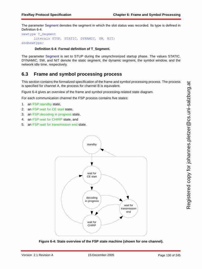
FlexRay Protocol Specification Chapter 6: Frame and Symbol Processing
Reg
iste
red
copy
for
joha
nnes
.ple
tzer
@cs
.uni
-sal
zbur
g.at
The parameter Segment denotes the segment in which the slot status was recorded. Its type is defined inDefinition 6-4.newtype T_Segment
literals STUP, STATIC, DYNAMIC, SW, NIT;endnewtype;
Definition 6-4: Formal definition of T_Segment.
The parameter Segment is set to STUP during the unsynchronized startup phase. The values STATIC,DYNAMIC, SW, and NIT denote the static segment, the dynamic segment, the symbol window, and thenetwork idle time, respectively.
6.3 Frame and symbol processing process
This section contains the formalized specification of the frame and symbol processing process. The processis specified for channel A, the process for channel B is equivalent.
Figure 6-4 gives an overview of the frame and symbol processing-related state diagram.
For each communication channel the FSP process contains five states:
1. an FSP:standby state,
2. an FSP:wait for CE start state,
3. an FSP:decoding in progress state,
4. an FSP:wait for CHIRP state, and
5. an FSP:wait for transmission end state.
Figure 6-4: State overview of the FSP state machine (shown for one channel).
wait forCE start
decodingin progress
wait forCHIRP
wait fortransmission
end
standby
Version 2.1 Revision A 15-December-2005 Page 130 of 245
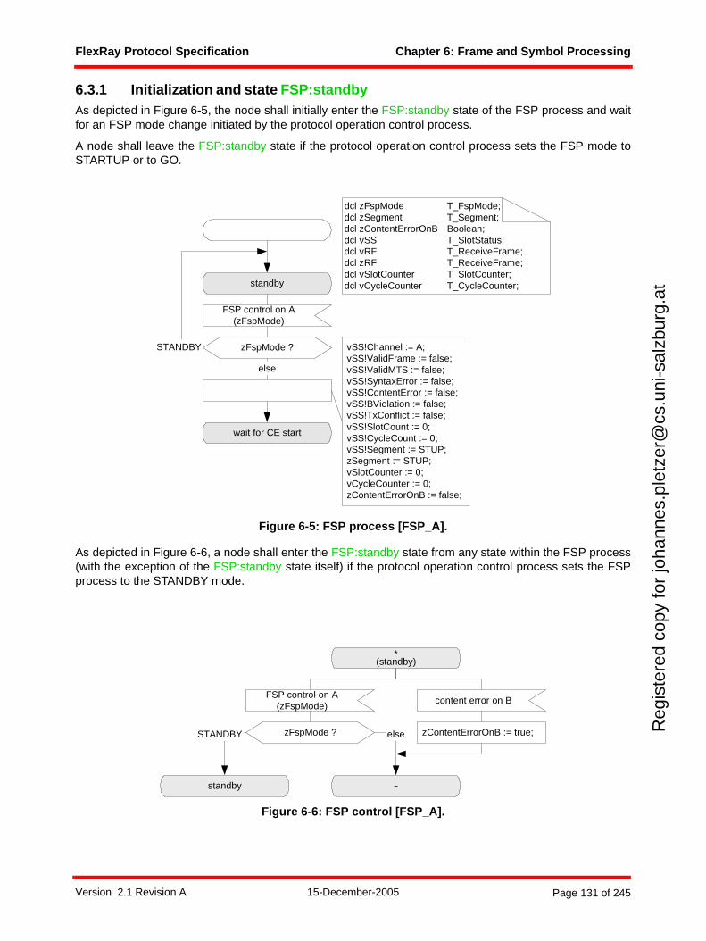
FlexRay Protocol Specification Chapter 6: Frame and Symbol Processing
Reg
iste
red
copy
for
joha
nnes
.ple
tzer
@cs
.uni
-sal
zbur
g.at
6.3.1 Initialization and state FSP:standbyAs depicted in Figure 6-5, the node shall initially enter the FSP:standby state of the FSP process and waitfor an FSP mode change initiated by the protocol operation control process.
A node shall leave the FSP:standby state if the protocol operation control process sets the FSP mode toSTARTUP or to GO.
Figure 6-5: FSP process [FSP_A].
As depicted in Figure 6-6, a node shall enter the FSP:standby state from any state within the FSP process(with the exception of the FSP:standby state itself) if the protocol operation control process sets the FSPprocess to the STANDBY mode.
Figure 6-6: FSP control [FSP_A].
else
standby
FSP control on A(zFspMode)
zFspMode ?STANDBY
wait for CE start
dcl zFspMode T_FspMode;dcl zSegment T_Segment;dcl zContentErrorOnB Boolean;dcl vSS T_SlotStatus;dcl vRF T_ReceiveFrame;dcl zRF T_ReceiveFrame;dcl vSlotCounter T_SlotCounter;dcl vCycleCounter T_CycleCounter;
vSS!Channel := A;vSS!ValidFrame := false;vSS!ValidMTS := false;vSS!SyntaxError := false;vSS!ContentError := false;vSS!BViolation := false;vSS!TxConflict := false;vSS!SlotCount := 0;vSS!CycleCount := 0;vSS!Segment := STUP;zSegment := STUP;vSlotCounter := 0;vCycleCounter := 0;zContentErrorOnB := false;
*(standby)
FSP control on A(zFspMode)
zFspMode ?
-standby
STANDBY else
content error on B
zContentErrorOnB := true;
Version 2.1 Revision A 15-December-2005 Page 131 of 245
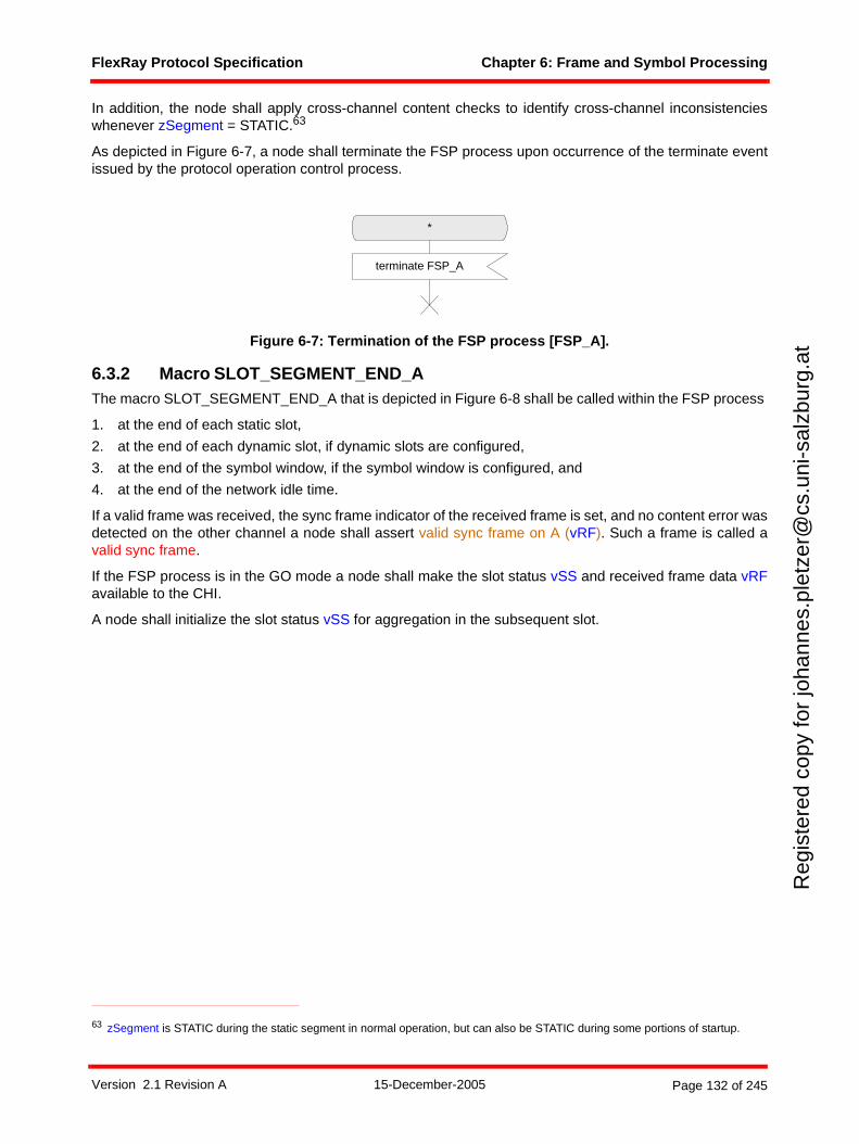
FlexRay Protocol Specification Chapter 6: Frame and Symbol Processing
Reg
iste
red
copy
for
joha
nnes
.ple
tzer
@cs
.uni
-sal
zbur
g.at
In addition, the node shall apply cross-channel content checks to identify cross-channel inconsistencieswhenever zSegment = STATIC.63
As depicted in Figure 6-7, a node shall terminate the FSP process upon occurrence of the terminate eventissued by the protocol operation control process.
Figure 6-7: Termination of the FSP process [FSP_A].
6.3.2 Macro SLOT_SEGMENT_END_AThe macro SLOT_SEGMENT_END_A that is depicted in Figure 6-8 shall be called within the FSP process
1. at the end of each static slot,
2. at the end of each dynamic slot, if dynamic slots are configured,
3. at the end of the symbol window, if the symbol window is configured, and
4. at the end of the network idle time.
If a valid frame was received, the sync frame indicator of the received frame is set, and no content error wasdetected on the other channel a node shall assert valid sync frame on A (vRF). Such a frame is called avalid sync frame.
If the FSP process is in the GO mode a node shall make the slot status vSS and received frame data vRFavailable to the CHI.
A node shall initialize the slot status vSS for aggregation in the subsequent slot.
63 zSegment is STATIC during the static segment in normal operation, but can also be STATIC during some portions of startup.
*
terminate FSP_A
Version 2.1 Revision A 15-December-2005 Page 132 of 245
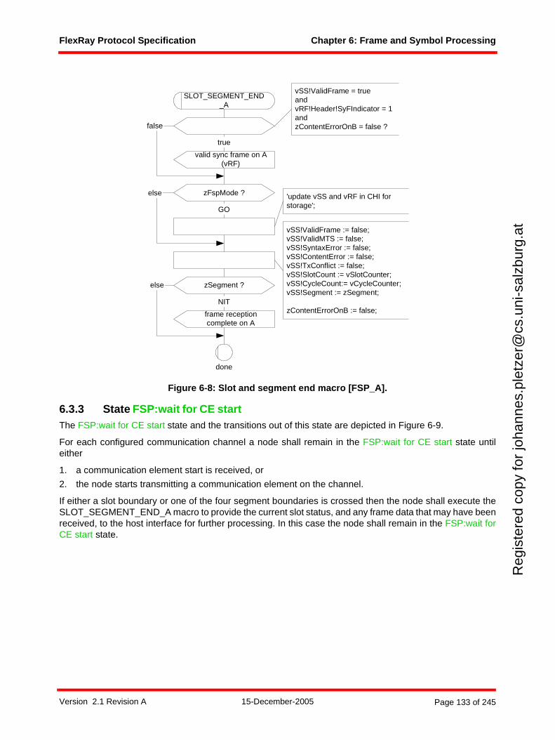
FlexRay Protocol Specification Chapter 6: Frame and Symbol Processing
Reg
iste
red
copy
for
joha
nnes
.ple
tzer
@cs
.uni
-sal
zbur
g.at
Figure 6-8: Slot and segment end macro [FSP_A].
6.3.3 State FSP:wait for CE startThe FSP:wait for CE start state and the transitions out of this state are depicted in Figure 6-9.
For each configured communication channel a node shall remain in the FSP:wait for CE start state untileither
1. a communication element start is received, or
2. the node starts transmitting a communication element on the channel.
If either a slot boundary or one of the four segment boundaries is crossed then the node shall execute theSLOT_SEGMENT_END_A macro to provide the current slot status, and any frame data that may have beenreceived, to the host interface for further processing. In this case the node shall remain in the FSP:wait forCE start state.
vSS!ValidFrame := false;vSS!ValidMTS := false;vSS!SyntaxError := false;vSS!ContentError := false;vSS!TxConflict := false;vSS!SlotCount := vSlotCounter;vSS!CycleCount:= vCycleCounter;vSS!Segment := zSegment;
zContentErrorOnB := false;
done
SLOT_SEGMENT_END_A
false
valid sync frame on A(vRF)
true
vSS!ValidFrame = trueandvRF!Header!SyFIndicator = 1andzContentErrorOnB = false ?
zFspMode ?
GO
'update vSS and vRF in CHI forstorage';
else
zSegment ?
frame receptioncomplete on A
NIT
else
Version 2.1 Revision A 15-December-2005 Page 133 of 245
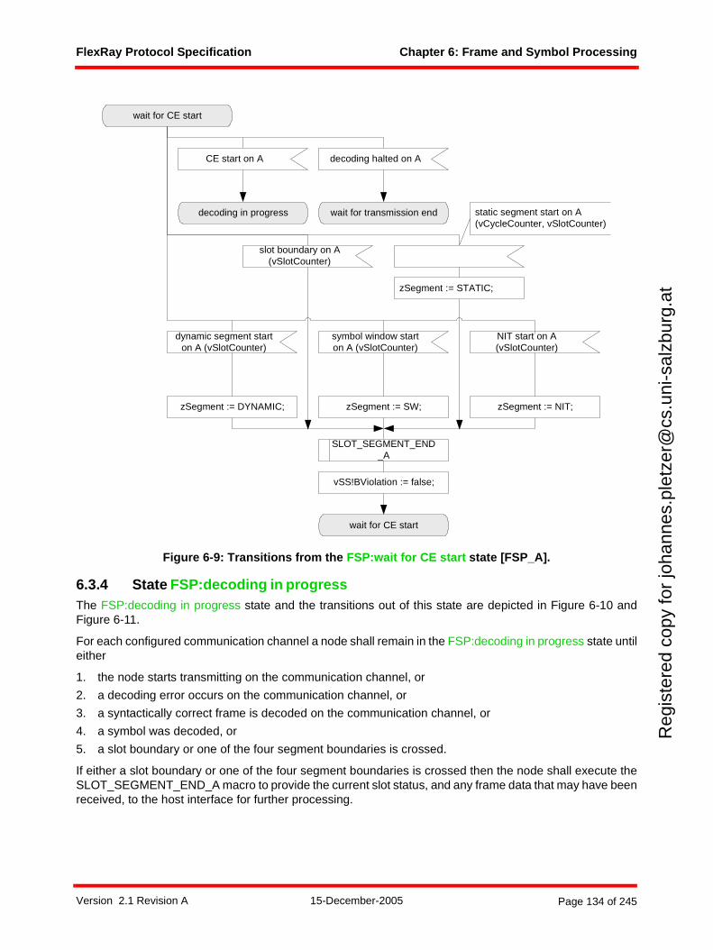
FlexRay Protocol Specification Chapter 6: Frame and Symbol Processing
Reg
iste
red
copy
for
joha
nnes
.ple
tzer
@cs
.uni
-sal
zbur
g.at
Figure 6-9: Transitions from the FSP:wait for CE start state [FSP_A].
6.3.4 State FSP:decoding in progressThe FSP:decoding in progress state and the transitions out of this state are depicted in Figure 6-10 andFigure 6-11.
For each configured communication channel a node shall remain in the FSP:decoding in progress state untileither
1. the node starts transmitting on the communication channel, or
2. a decoding error occurs on the communication channel, or
3. a syntactically correct frame is decoded on the communication channel, or
4. a symbol was decoded, or
5. a slot boundary or one of the four segment boundaries is crossed.
If either a slot boundary or one of the four segment boundaries is crossed then the node shall execute theSLOT_SEGMENT_END_A macro to provide the current slot status, and any frame data that may have beenreceived, to the host interface for further processing.
symbol window starton A (vSlotCounter)
NIT start on A(vSlotCounter)
wait for CE start
zSegment := SW; zSegment := NIT;
vSS!BViolation := false;
wait for CE start
CE start on A
decoding in progress wait for transmission end
dynamic segment starton A (vSlotCounter)
zSegment := DYNAMIC;
static segment start on A(vCycleCounter, vSlotCounter)
slot boundary on A(vSlotCounter)
zSegment := STATIC;
SLOT_SEGMENT_END_A
decoding halted on A
Version 2.1 Revision A 15-December-2005 Page 134 of 245
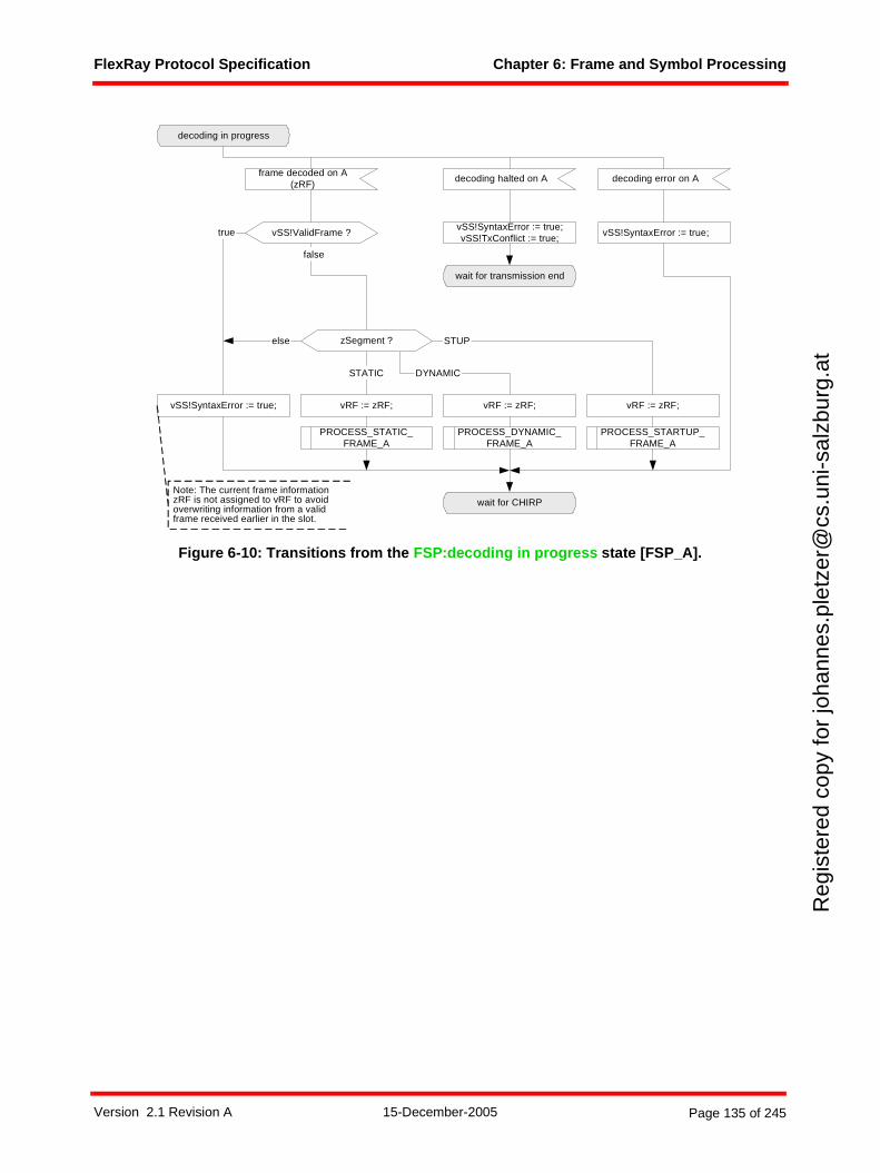
FlexRay Protocol Specification Chapter 6: Frame and Symbol Processing
Reg
iste
red
copy
for
joha
nnes
.ple
tzer
@cs
.uni
-sal
zbur
g.at
Figure 6-10: Transitions from the FSP:decoding in progress state [FSP_A].
decoding error on Aframe decoded on A
(zRF)
decoding in progress
wait for CHIRP
decoding halted on A
PROCESS_STATIC_FRAME_A
STATIC
vSS!SyntaxError := true;vSS!SyntaxError := true;vSS!TxConflict := true;
PROCESS_DYNAMIC_FRAME_A
DYNAMIC
PROCESS_STARTUP_FRAME_A
STUP
wait for transmission end
vSS!ValidFrame ?
zSegment ?
false
vSS!SyntaxError := true;
else
true
vRF := zRF; vRF := zRF; vRF := zRF;
Note: The current frame informationzRF is not assigned to vRF to avoidoverwriting information from a validframe received earlier in the slot.
Version 2.1 Revision A 15-December-2005 Page 135 of 245
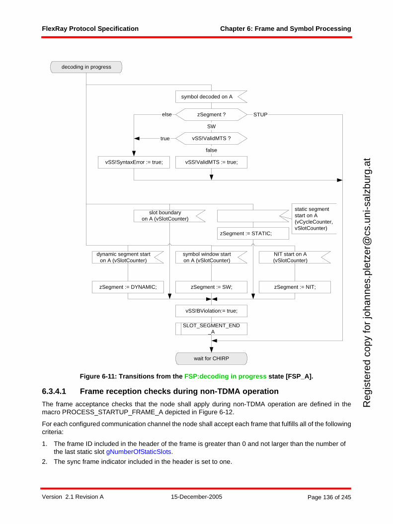
FlexRay Protocol Specification Chapter 6: Frame and Symbol Processing
Reg
iste
red
copy
for
joha
nnes
.ple
tzer
@cs
.uni
-sal
zbur
g.at
Figure 6-11: Transitions from the FSP:decoding in progress state [FSP_A].
6.3.4.1 Frame reception checks during non-TDMA operation
The frame acceptance checks that the node shall apply during non-TDMA operation are defined in themacro PROCESS_STARTUP_FRAME_A depicted in Figure 6-12.
For each configured communication channel the node shall accept each frame that fulfills all of the followingcriteria:
1. The frame ID included in the header of the frame is greater than 0 and not larger than the number of the last static slot gNumberOfStaticSlots.
2. The sync frame indicator included in the header is set to one.
static segmentstart on A(vCycleCounter,vSlotCounter)
dynamic segment starton A (vSlotCounter)
symbol window starton A (vSlotCounter)
NIT start on A(vSlotCounter)
symbol decoded on A
wait for CHIRP
vSS!ValidMTS := true;
SW
zSegment := DYNAMIC; zSegment := SW; zSegment := NIT;
false
vSS!SyntaxError := true;
else
vSS!BViolation:= true;
zSegment := STATIC;
slot boundaryon A (vSlotCounter)
SLOT_SEGMENT_END_A
decoding in progress
STUPzSegment ?
vSS!ValidMTS ?true
Version 2.1 Revision A 15-December-2005 Page 136 of 245
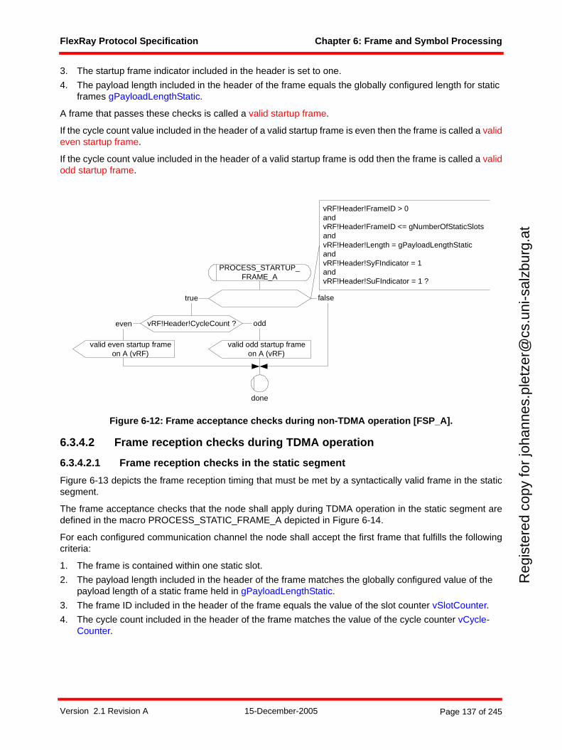
FlexRay Protocol Specification Chapter 6: Frame and Symbol Processing
Reg
iste
red
copy
for
joha
nnes
.ple
tzer
@cs
.uni
-sal
zbur
g.at
3. The startup frame indicator included in the header is set to one.
4. The payload length included in the header of the frame equals the globally configured length for static frames gPayloadLengthStatic.
A frame that passes these checks is called a valid startup frame.
If the cycle count value included in the header of a valid startup frame is even then the frame is called a valideven startup frame.
If the cycle count value included in the header of a valid startup frame is odd then the frame is called a validodd startup frame.
Figure 6-12: Frame acceptance checks during non-TDMA operation [FSP_A].
6.3.4.2 Frame reception checks during TDMA operation
6.3.4.2.1 Frame reception checks in the static segment
Figure 6-13 depicts the frame reception timing that must be met by a syntactically valid frame in the staticsegment.
The frame acceptance checks that the node shall apply during TDMA operation in the static segment aredefined in the macro PROCESS_STATIC_FRAME_A depicted in Figure 6-14.
For each configured communication channel the node shall accept the first frame that fulfills the followingcriteria:
1. The frame is contained within one static slot.
2. The payload length included in the header of the frame matches the globally configured value of the payload length of a static frame held in gPayloadLengthStatic.
3. The frame ID included in the header of the frame equals the value of the slot counter vSlotCounter.
4. The cycle count included in the header of the frame matches the value of the cycle counter vCycle-Counter.
vRF!Header!FrameID > 0andvRF!Header!FrameID <= gNumberOfStaticSlotsandvRF!Header!Length = gPayloadLengthStaticandvRF!Header!SyFIndicator = 1andvRF!Header!SuFIndicator = 1 ?
false
vRF!Header!CycleCount ?
true
oddeven
PROCESS_STARTUP_FRAME_A
done
valid odd startup frameon A (vRF)
valid even startup frameon A (vRF)
Version 2.1 Revision A 15-December-2005 Page 137 of 245
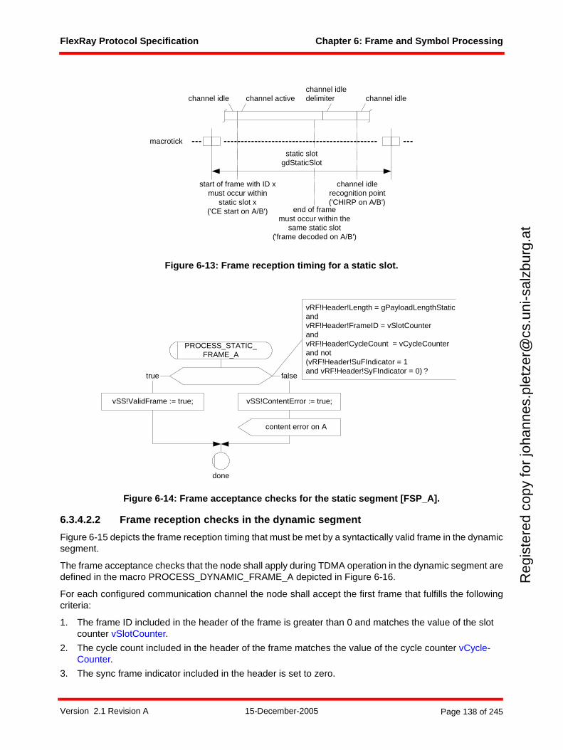
FlexRay Protocol Specification Chapter 6: Frame and Symbol Processing
Reg
iste
red
copy
for
joha
nnes
.ple
tzer
@cs
.uni
-sal
zbur
g.at
Figure 6-13: Frame reception timing for a static slot.
Figure 6-14: Frame acceptance checks for the static segment [FSP_A].
6.3.4.2.2 Frame reception checks in the dynamic segment
Figure 6-15 depicts the frame reception timing that must be met by a syntactically valid frame in the dynamicsegment.
The frame acceptance checks that the node shall apply during TDMA operation in the dynamic segment aredefined in the macro PROCESS_DYNAMIC_FRAME_A depicted in Figure 6-16.
For each configured communication channel the node shall accept the first frame that fulfills the followingcriteria:
1. The frame ID included in the header of the frame is greater than 0 and matches the value of the slot counter vSlotCounter.
2. The cycle count included in the header of the frame matches the value of the cycle counter vCycle-Counter.
3. The sync frame indicator included in the header is set to zero.
macrotick
channel idledelimiterchannel active channel idlechannel idle
start of frame with ID xmust occur within
static slot x('CE start on A/B') end of frame
must occur within thesame static slot
('frame decoded on A/B')
channel idlerecognition point('CHIRP on A/B')
static slotgdStaticSlot
vRF!Header!Length = gPayloadLengthStaticandvRF!Header!FrameID = vSlotCounterandvRF!Header!CycleCount = vCycleCounterand not(vRF!Header!SuFIndicator = 1and vRF!Header!SyFIndicator = 0) ?
done
PROCESS_STATIC_FRAME_A
vSS!ContentError := true;vSS!ValidFrame := true;
true false
content error on A
Version 2.1 Revision A 15-December-2005 Page 138 of 245
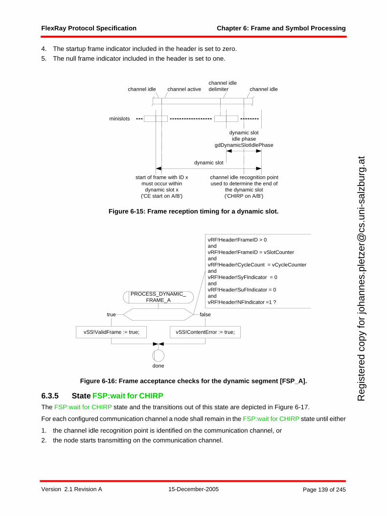
FlexRay Protocol Specification Chapter 6: Frame and Symbol Processing
Reg
iste
red
copy
for
joha
nnes
.ple
tzer
@cs
.uni
-sal
zbur
g.at
4. The startup frame indicator included in the header is set to zero.
5. The null frame indicator included in the header is set to one.
Figure 6-15: Frame reception timing for a dynamic slot.
Figure 6-16: Frame acceptance checks for the dynamic segment [FSP_A].
6.3.5 State FSP:wait for CHIRPThe FSP:wait for CHIRP state and the transitions out of this state are depicted in Figure 6-17.
For each configured communication channel a node shall remain in the FSP:wait for CHIRP state until either
1. the channel idle recognition point is identified on the communication channel, or
2. the node starts transmitting on the communication channel.
dynamic slot
dynamic slotidle phase
gdDynamicSlotIdlePhase
channel idledelimiter channel idlechannel activechannel idle
start of frame with ID xmust occur within
dynamic slot x('CE start on A/B')
channel idle recognition pointused to determine the end of
the dynamic slot('CHIRP on A/B')
minislots
vRF!Header!FrameID > 0andvRF!Header!FrameID = vSlotCounterandvRF!Header!CycleCount = vCycleCounterandvRF!Header!SyFIndicator = 0andvRF!Header!SuFIndicator = 0andvRF!Header!NFIndicator =1 ?
done
PROCESS_DYNAMIC_FRAME_A
vSS!ContentError := true;vSS!ValidFrame := true;
true false
Version 2.1 Revision A 15-December-2005 Page 139 of 245
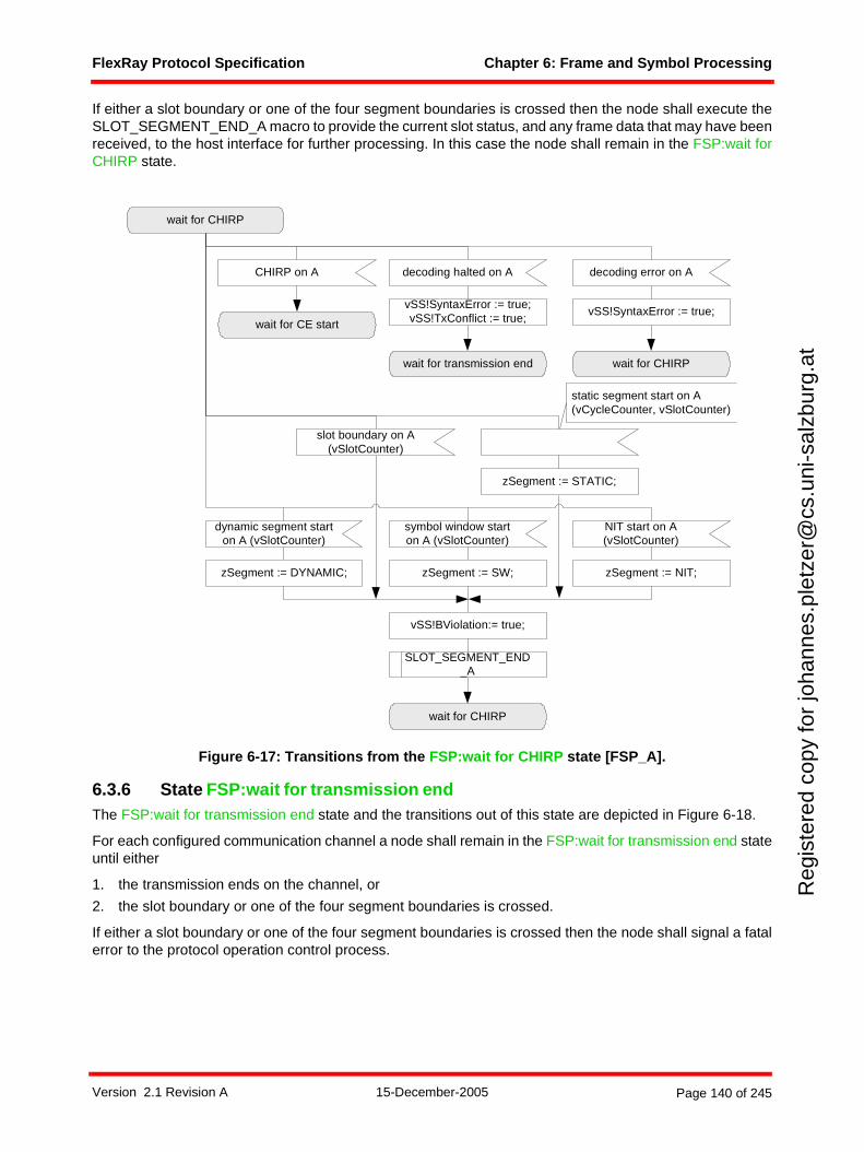
FlexRay Protocol Specification Chapter 6: Frame and Symbol Processing
Reg
iste
red
copy
for
joha
nnes
.ple
tzer
@cs
.uni
-sal
zbur
g.at
If either a slot boundary or one of the four segment boundaries is crossed then the node shall execute theSLOT_SEGMENT_END_A macro to provide the current slot status, and any frame data that may have beenreceived, to the host interface for further processing. In this case the node shall remain in the FSP:wait forCHIRP state.
Figure 6-17: Transitions from the FSP:wait for CHIRP state [FSP_A].
6.3.6 State FSP:wait for transmission endThe FSP:wait for transmission end state and the transitions out of this state are depicted in Figure 6-18.
For each configured communication channel a node shall remain in the FSP:wait for transmission end stateuntil either
1. the transmission ends on the channel, or
2. the slot boundary or one of the four segment boundaries is crossed.
If either a slot boundary or one of the four segment boundaries is crossed then the node shall signal a fatalerror to the protocol operation control process.
wait for CHIRP
dynamic segment starton A (vSlotCounter)
symbol window starton A (vSlotCounter)
NIT start on A(vSlotCounter)
CHIRP on A
wait for CE start
wait for transmission end
vSS!SyntaxError := true;vSS!TxConflict := true;
wait for CHIRP
zSegment := DYNAMIC; zSegment := SW; zSegment := NIT;
vSS!BViolation:= true;
static segment start on A(vCycleCounter, vSlotCounter)
slot boundary on A(vSlotCounter)
zSegment := STATIC;
SLOT_SEGMENT_END_A
decoding halted on A
vSS!SyntaxError := true;
decoding error on A
wait for CHIRP
Version 2.1 Revision A 15-December-2005 Page 140 of 245
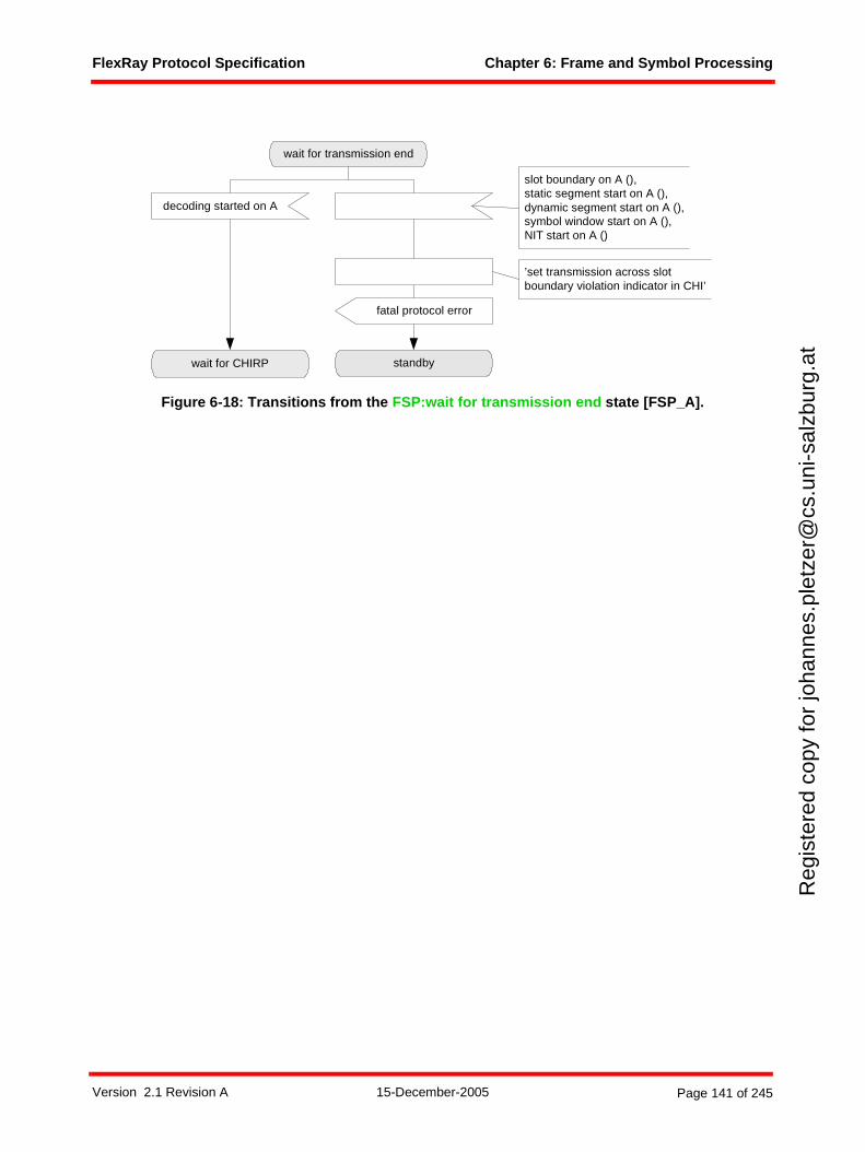
FlexRay Protocol Specification Chapter 6: Frame and Symbol Processing
Reg
iste
red
copy
for
joha
nnes
.ple
tzer
@cs
.uni
-sal
zbur
g.at
Figure 6-18: Transitions from the FSP:wait for transmission end state [FSP_A].
wait for transmission end
decoding started on A
fatal protocol error
wait for CHIRP standby
slot boundary on A (),static segment start on A (),dynamic segment start on A (),symbol window start on A (),NIT start on A ()
’set transmission across slotboundary violation indicator in CHI’
Version 2.1 Revision A 15-December-2005 Page 141 of 245
FlexRay Protocol Specification Chapter 7: Wakeup and Startup
Reg
iste
red
copy
for
joha
nnes
.ple
tzer
@cs
.uni
-sal
zbur
g.at
Chapter 7Wakeup and Startup
This chapter describes the procession of a FlexRay cluster from sleep mode to full operation and theintegration of newly configured nodes into a FlexRay cluster already in operation.
First the cluster wakeup is described in detail. Some application notes regarding the interaction betweencommunication controller and host are provided.
Following the wakeup section, communication startup and reintegration is described. This section alsodescribes the integration of nodes into a communication cluster.
7.1 Cluster wakeup
This section describes the procedure64 used by communication controllers to initiate the cluster wakeup.
7.1.1 PrinciplesThe minimum prerequisite for a cluster wakeup is that the receivers of all bus drivers be supplied with power.A bus driver has the ability to wake up the other components of its node when it receives a wakeup patternon its channel. At least one node in the cluster needs an external wakeup source.
The host completely controls the wakeup procedure65. The communication controller provides the host theability to transmit a special wakeup pattern (see Chapter 3) on each of its available channels separately.The wakeup pattern must not be transmitted on both channels at the same time. This is done to prevent afaulty node from disturbing communication on both channels simultaneously with the transmission. The hostmust configure which channel the communication controller shall wake up. The communication controllerensures that ongoing communication on this channel is not disturbed.
The wakeup pattern then causes any fault-free receiving node to wake up if it is still asleep. Generally, thebus driver of the receiving node recognizes the wakeup pattern and triggers the node wakeup. The commu-nication controller needs to recognize the wakeup pattern only during the wakeup (for collision resolution)and startup phases.
The communication controller cannot verify whether all nodes connected to the configured channel areawake after the transmission of the wakeup pattern66 since these nodes cannot give feedback until thestartup phase. The host shall be aware of possible failures of the wakeup and act accordingly.
The wakeup procedure supports the ability for single-channel devices in a dual-channel system to initiatecluster wakeup by transmitting the wakeup pattern on the single channel to which they are connected.Another node, which has access to both channels, then assumes the responsibility for waking up the otherchannel and transmits a wakeup pattern on it (see section 7.1.4.1).
64 To simplify discussion, the sequence of tasks executed while triggering the cluster wakeup is referred to here as the wakeup "procedure" even though it is realized as an SDL macro, and not an SDL procedure. The normal grammatical use of the term is intended rather than the precise SDL definition. Since SDL processes are not used in the wakeup mechanism, the usage does not introduce ambiguity.
65 The host may force a mode change from wakeup mode to the POC:ready state. Note, however, that a forced mode-change to the POC:ready state during wakeup may have consequences regarding the consistency of the cluster.
66 For example, the transmission unit of the bus driver may be faulty.
Version 2.1 Revision A 15-December-2005 Page 142 of 245
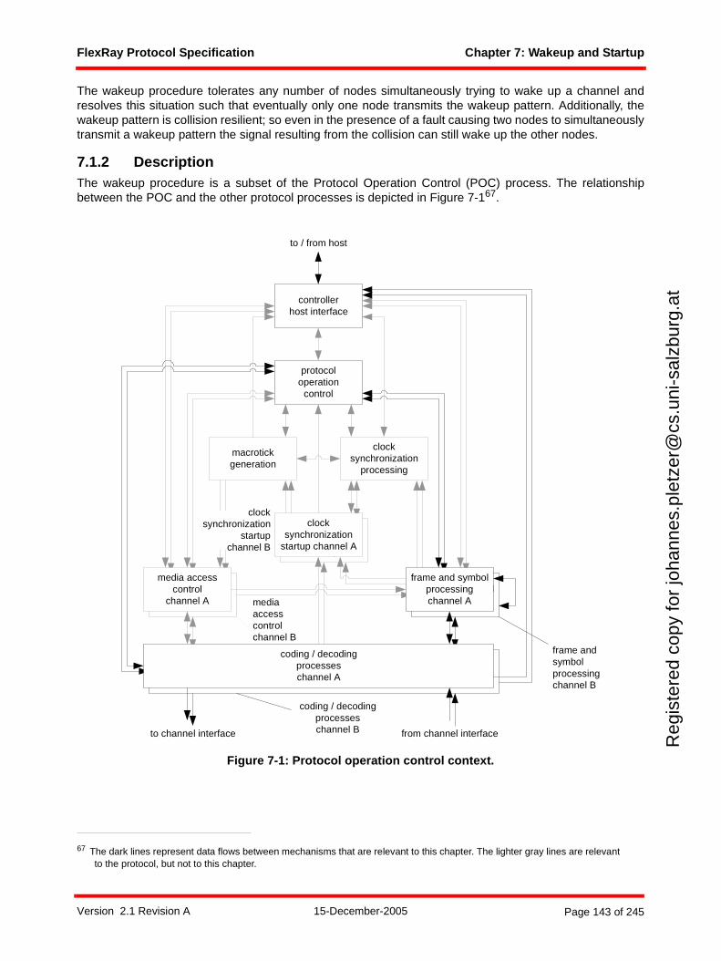
FlexRay Protocol Specification Chapter 7: Wakeup and Startup
Reg
iste
red
copy
for
joha
nnes
.ple
tzer
@cs
.uni
-sal
zbur
g.at
The wakeup procedure tolerates any number of nodes simultaneously trying to wake up a channel andresolves this situation such that eventually only one node transmits the wakeup pattern. Additionally, thewakeup pattern is collision resilient; so even in the presence of a fault causing two nodes to simultaneouslytransmit a wakeup pattern the signal resulting from the collision can still wake up the other nodes.
7.1.2 DescriptionThe wakeup procedure is a subset of the Protocol Operation Control (POC) process. The relationshipbetween the POC and the other protocol processes is depicted in Figure 7-167.
Figure 7-1: Protocol operation control context.
67 The dark lines represent data flows between mechanisms that are relevant to this chapter. The lighter gray lines are relevant to the protocol, but not to this chapter.
frame and symbolprocessing
media accesscontrol
clocksynchronization
startup
macrotickgeneration
clocksynchronization
processing
protocoloperation
control
controllerhost interface
coding / decodingprocesseschannel A
frame and symbolprocessingchannel A
media accesscontrol
channel A
clocksynchronization
startup channel A
to channel interface from channel interface
to / from host
mediaaccesscontrolchannel B
coding / decodingprocesseschannel B
frame andsymbolprocessingchannel B
clocksynchronization
startupchannel B
Version 2.1 Revision A 15-December-2005 Page 143 of 245
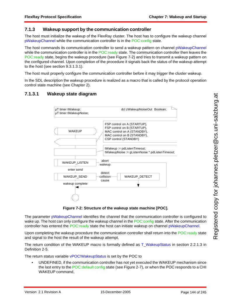
FlexRay Protocol Specification Chapter 7: Wakeup and Startup
Reg
iste
red
copy
for
joha
nnes
.ple
tzer
@cs
.uni
-sal
zbur
g.at
7.1.3 Wakeup support by the communication controllerThe host must initialize the wakeup of the FlexRay cluster. The host has to configure the wakeup channelpWakeupChannel while the communication controller is in the POC:config state.
The host commands its communication controller to send a wakeup pattern on channel pWakeupChannelwhile the communication controller is in the POC:ready state. The communication controller then leaves thePOC:ready state, begins the wakeup procedure (see Figure 7-2) and tries to transmit a wakeup pattern onthe configured channel. Upon completion of the procedure it signals back the status of the wakeup attemptto the host (see section 9.3.1.3.1).
The host must properly configure the communication controller before it may trigger the cluster wakeup.
In the SDL description the wakeup procedure is realized as a macro that is called by the protocol operationcontrol state machine (see Chapter 2).
7.1.3.1 Wakeup state diagram
Figure 7-2: Structure of the wakeup state machine [POC].
The parameter pWakeupChannel identifies the channel that the communication controller is configured towake up. The host can only configure the wakeup channel in the POC:config state. After the communicationcontroller has entered the POC:ready state the host can initiate wakeup on channel pWakeupChannel.
Upon completing the wakeup procedure the communication controller shall return into the POC:ready stateand signal to the host the result of the wakeup attempt.
The return condition of the WAKEUP macro is formally defined as T_WakeupStatus in section 2.2.1.3 inDefinition 2-5.
The return status variable vPOC!WakeupStatus is set by the POC to
• UNDEFINED, if the communication controller has not yet executed the WAKEUP mechanism sincethe last entry to the POC:default config state (see Figure 2-7), or when the POC responds to a CHIWAKEUP command,
µT timer tWakeup; dcl zWakeupNoiseOut Boolean;µT timer tWakeupNoise;
WAKEUP
WAKEUP_LISTEN
enter send
abortwakeup
WAKEUP_SEND
wakeup complete
detectcollisioncause
tWakeup := pdListenTimeout;tWakeupNoise := gListenNoise * pdListenTimeout;
FSP control on A (STARTUP),FSP control on B (STARTUP),MAC control on A (STANDBY),MAC control on B (STANDBY),CSP control (STANDBY)
WAKEUP_DETECT
Version 2.1 Revision A 15-December-2005 Page 144 of 245
FlexRay Protocol Specification Chapter 7: Wakeup and Startup
Reg
iste
red
copy
for
joha
nnes
.ple
tzer
@cs
.uni
-sal
zbur
g.at
• RECEIVED_HEADER, if the communication controller has received a frame header without codingviolation on either channel during the initial listen phase,
• RECEIVED_WUP, if the communication controller has received a valid wakeup pattern on channelpWakeupChannel during the initial listen phase,
• COLLISION_HEADER, if the communication controller has detected a collision during wakeuppattern transmission by receiving a valid header during the ensuing detection phase,
• COLLISION_WUP, if the communication controller has detected a collision during wakeup patterntransmission by receiving a valid wakeup pattern during the ensuing detection phase,
• COLLISION_UNKNOWN, if the communication controller has detected a collision but did not detecta subsequent reception event that would allow the collision to be categorized as either COLLI-SION_HEADER or COLLISION_WUP,
• TRANSMITTED, if the wakeup pattern was completely transmitted.
Version 2.1 Revision A 15-December-2005 Page 145 of 245
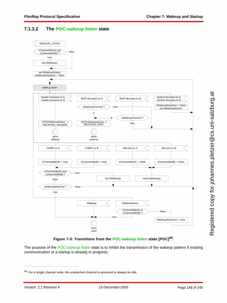
FlexRay Protocol Specification Chapter 7: Wakeup and Startup
Reg
iste
red
copy
for
joha
nnes
.ple
tzer
@cs
.uni
-sal
zbur
g.at
7.1.3.2 The POC:wakeup listen state
Figure 7-3: Transitions from the POC:wakeup listen state [POC]68.
The purpose of the POC:wakeup listen state is to inhibit the transmission of the wakeup pattern if existingcommunication or a startup is already in progress.
68 For a single channel node, the unattached channel is assumed to always be idle.
set (tWakeupNoise);zWakeupNoiseOut := false;
wakeup listen
true
false
tWakeupNoise
WAKEUP_LISTEN
abortwakeup
tWakeup
entersend
reset (tWakeup);false set (tWakeup);
true
CHIRP on A idle end on ACHIRP on B idle end on B
zChannelIdle(A) := true; zChannelIdle(A) := false;zChannelIdle(B) := true; zChannelIdle(B) := false;
zChannelIdle(A) andzChannelIdle(B) ?
zChannelIdle(A) andzChannelIdle(B) ?
false
set (tWakeup);
true
vPOC!WakeupStatus :=RECEIVED_HEADER;
header received on A,header received on B
abortwakeup
zWakeupNoiseOut := false;set (tWakeupNoise);
symbol decoded on A,symbol decoded on B
vPOC!WakeupStatus :=RECEIVED_WUP;
WUP decoded on A WUP decoded on B
B
A
zWakeupNoiseOut ?
zChannelIdle(A) orzChannelIdle(B) ?
zWakeupNoiseOut := true;
false
true
pWakeupChannel ?
pWakeupChannel ?
else
else
Version 2.1 Revision A 15-December-2005 Page 146 of 245
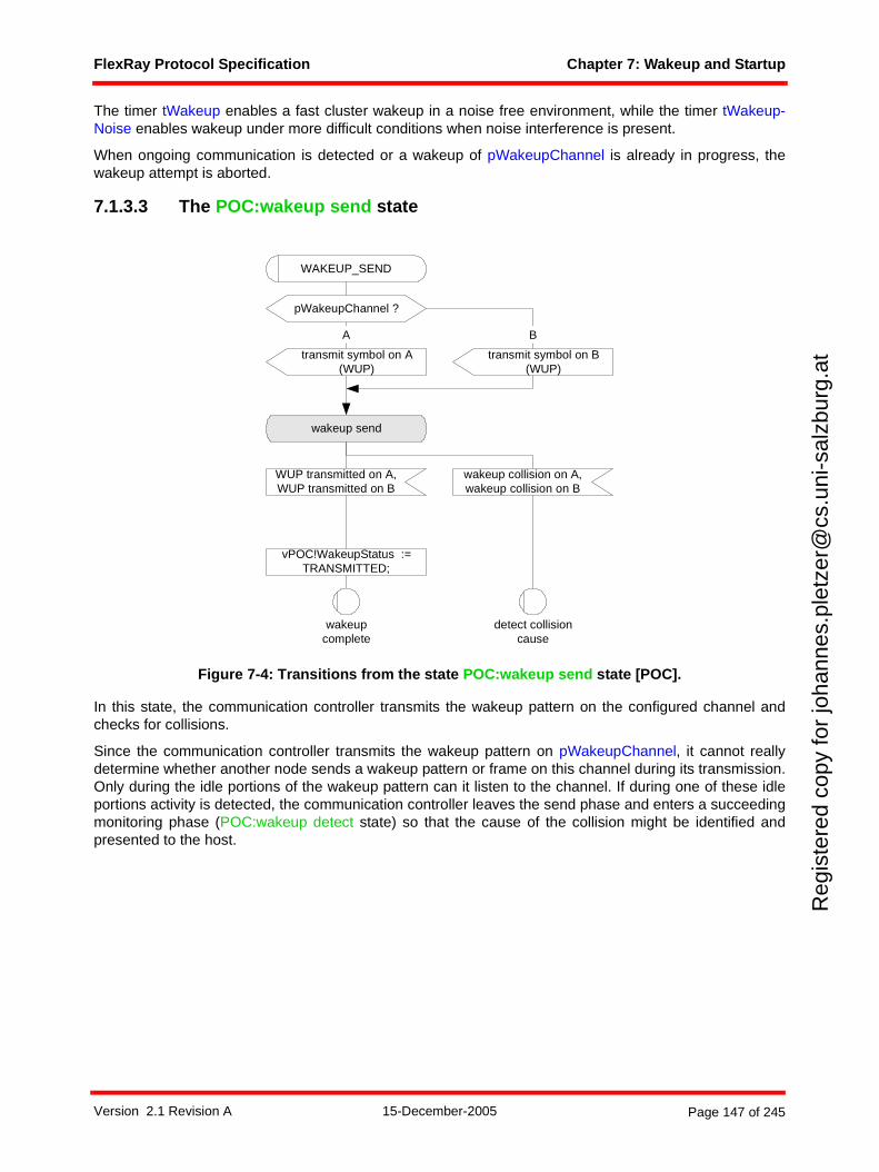
FlexRay Protocol Specification Chapter 7: Wakeup and Startup
Reg
iste
red
copy
for
joha
nnes
.ple
tzer
@cs
.uni
-sal
zbur
g.at
The timer tWakeup enables a fast cluster wakeup in a noise free environment, while the timer tWakeup-Noise enables wakeup under more difficult conditions when noise interference is present.
When ongoing communication is detected or a wakeup of pWakeupChannel is already in progress, thewakeup attempt is aborted.
7.1.3.3 The POC:wakeup send state
Figure 7-4: Transitions from the state POC:wakeup send state [POC].
In this state, the communication controller transmits the wakeup pattern on the configured channel andchecks for collisions.
Since the communication controller transmits the wakeup pattern on pWakeupChannel, it cannot reallydetermine whether another node sends a wakeup pattern or frame on this channel during its transmission.Only during the idle portions of the wakeup pattern can it listen to the channel. If during one of these idleportions activity is detected, the communication controller leaves the send phase and enters a succeedingmonitoring phase (POC:wakeup detect state) so that the cause of the collision might be identified andpresented to the host.
wakeup send
vPOC!WakeupStatus :=TRANSMITTED;
A
WUP transmitted on A,WUP transmitted on B
transmit symbol on A(WUP)
wakeupcomplete
WAKEUP_SEND
detect collisioncause
wakeup collision on A,wakeup collision on B
pWakeupChannel ?
transmit symbol on B(WUP)
B
Version 2.1 Revision A 15-December-2005 Page 147 of 245
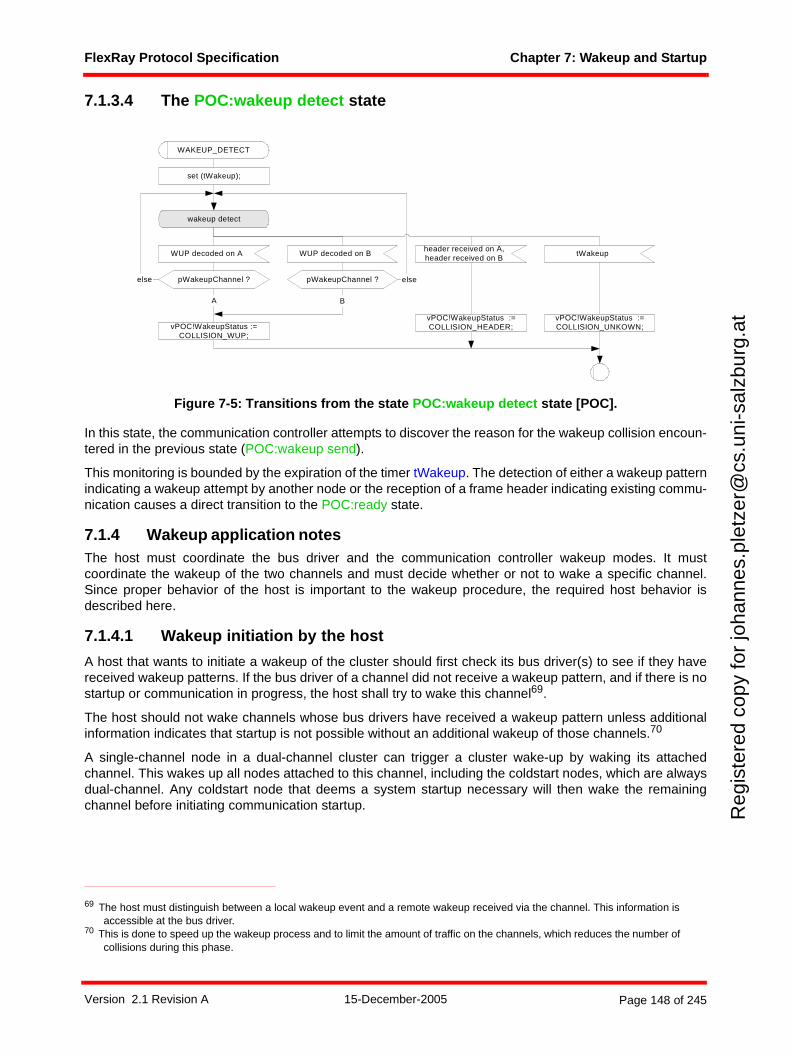
FlexRay Protocol Specification Chapter 7: Wakeup and Startup
Reg
iste
red
copy
for
joha
nnes
.ple
tzer
@cs
.uni
-sal
zbur
g.at
7.1.3.4 The POC:wakeup detect state
Figure 7-5: Transitions from the state POC:wakeup detect state [POC].
In this state, the communication controller attempts to discover the reason for the wakeup collision encoun-tered in the previous state (POC:wakeup send).
This monitoring is bounded by the expiration of the timer tWakeup. The detection of either a wakeup patternindicating a wakeup attempt by another node or the reception of a frame header indicating existing commu-nication causes a direct transition to the POC:ready state.
7.1.4 Wakeup application notesThe host must coordinate the bus driver and the communication controller wakeup modes. It mustcoordinate the wakeup of the two channels and must decide whether or not to wake a specific channel.Since proper behavior of the host is important to the wakeup procedure, the required host behavior isdescribed here.
7.1.4.1 Wakeup initiation by the host
A host that wants to initiate a wakeup of the cluster should first check its bus driver(s) to see if they havereceived wakeup patterns. If the bus driver of a channel did not receive a wakeup pattern, and if there is nostartup or communication in progress, the host shall try to wake this channel69.
The host should not wake channels whose bus drivers have received a wakeup pattern unless additionalinformation indicates that startup is not possible without an additional wakeup of those channels.70
A single-channel node in a dual-channel cluster can trigger a cluster wake-up by waking its attachedchannel. This wakes up all nodes attached to this channel, including the coldstart nodes, which are alwaysdual-channel. Any coldstart node that deems a system startup necessary will then wake the remainingchannel before initiating communication startup.
69 The host must distinguish between a local wakeup event and a remote wakeup received via the channel. This information is accessible at the bus driver.
70 This is done to speed up the wakeup process and to limit the amount of traffic on the channels, which reduces the number of collisions during this phase.
wakeup detect
vPOC!WakeupStatus :=COLLISION_WUP;
vPOC!WakeupStatus :=COLLISION_HEADER;
set (tWakeup);
header received on A,header received on B
WAKEUP_DETECT
tWakeup
vPOC!WakeupStatus :=COLLISION_UNKOWN;
WUP decoded on A
A
WUP decoded on B
B
pWakeupChannel ? pWakeupChannel ?else else
Version 2.1 Revision A 15-December-2005 Page 148 of 245

FlexRay Protocol Specification Chapter 7: Wakeup and Startup
Reg
iste
red
copy
for
joha
nnes
.ple
tzer
@cs
.uni
-sal
zbur
g.at
7.1.4.1.1 Single-channel nodes
This section describes the wakeup behavior of single-channel nodes in single- or dual-channel clusters. Thebus driver is assumed to be in the BD_Sleep or BD_Standby mode. The host is assumed to havedetermined that a cluster wakeup should be triggered.
1. The host first configures the communication controller. The coldstart inhibit mode71 shall be entered by setting vColdStartInhibit to true.
2. The host checks whether a wakeup pattern was received by the bus driver.
3. The host puts the bus driver into the BD_Normal mode.
4. If a wakeup pattern was received by the bus driver, the node should enter the startup (step 9) instead of performing a wakeup.If no wakeup pattern received by the bus driver, the node may perform a wakeup of the attached chan-nel (which will eventually wake both channels of a dual-channel cluster).
5. The host configures pWakeupChannel to the attached channel.
6. The host commands the communication controller to begin the wakeup procedure.
7. After its wakeup attempt is complete the communication controller returns the result of the wakeup attempt.
8. The host commands the communication controller to leave the coldstart inhibit mode and to com-mence startup.
7.1.4.1.2 Dual-channel nodes
This section describes the wakeup behavior of dual-channel nodes in dual-channel clusters.
Figure 7-6: A short example of how the wakeup of two channels can be accomplished in a fault-tolerant way by coldstart nodes.72
A communication controller shall not send a wakeup pattern on both channels at the same time73. If it isnecessary to wake both channels, the host can only wake them one at a time.
71 This has no functional effect for non-coldstart nodes.72 Note that there is no requirement that a wakeup node be a coldstart node, or that a coldstart node be a wakeup node. In this
example the wakeup nodes are also coldstart nodes, but this is not required.73 This requirement ensures that an erroneous communication controller cannot disturb all ongoing communication by
transmitting wakeup patterns on both channels at the same time.
power off / reset
power off / reset
poweroff/reset
POC state
config
Node Awakeup/coldstart nodechannel A, B
Node Cnon coldstart nodechannel B
Channel A
B
wakeuplisten
wakeupsend
wakeuppattern
wakeuppattern
readywakeup
listenwakeup
send integration listenreadyconfig
ready ready coldstart listenNode Bwakeup/coldstart nodechannel A, B
coldstart listen
leave coldstartinhibit mode
wakechannel A
wake channel B
config readyintegration
listen
localwakeup event
Version 2.1 Revision A 15-December-2005 Page 149 of 245

FlexRay Protocol Specification Chapter 7: Wakeup and Startup
Reg
iste
red
copy
for
joha
nnes
.ple
tzer
@cs
.uni
-sal
zbur
g.at
To avoid certain types of failures, a single communication controller should not wake up both channels.Instead, a different controller should wake up each channel.
To accomplish this, a communication controller that has received a local wakeup event proceeds normallyand only wakes a single channel, e.g., channel A (see Figure 7-6). Following this, it does not wake the otherchannel but rather enters startup. If it is a coldstart node, the coldstart inhibit flag must be set to true, so thatit cannot actively initiate the cluster startup. Only after the node detects a wakeup pattern on channel Bshould it clear the coldstart inhibit flag and actively coldstart the cluster.
Two example wakeup strategies are now given as examples to demonstrate how cluster wakeup can beaccomplished. Neither strategy is concerned with the details of error recovery and therefore do not handlesome error situations that are likely to occur.
7.1.4.1.2.1 Wakeup pattern reception by the bus driver
The bus drivers are assumed to be in the BD_Sleep or BD_Standby mode. The host is assumed to havedetermined that a cluster wakeup should be triggered.
1. The host first configures the communication controller. It assumes both channels to be asleep. The
coldstart inhibit mode74 shall be set.
2. The host checks which of the bus drivers has received a wakeup pattern.
3. The host puts all bus drivers that have received a wakeup pattern into BD_Normal mode (these chan-nels can be assumed to be awake).
4. If both channels are awake, the host can proceed to startup (step 11).If both channels are asleep, the host shall wake up one of them.If one channel is asleep and one channel is awake, a non-coldstart host may wake up the channel that is asleep, but a coldstart host must wake up the channel that is asleep.
5. The host configures pWakeupChannel to the channel to be awakened.
6. The host activates the bus driver of pWakeupChannel.
7. The host commands the communication controller to begin the wakeup procedure.
8. The communication controller returns the result of the wakeup attempt.
9. If the result of the wakeup attempt is TRANSMITTED, the host assumes pWakeupChannel to be awake and proceeds to startup (step 11).If the result of the wakeup attempt is RECEIVED_HEADER or COLLISION_HEADER, the host can assume that both channels are awake. It activates any remaining sleeping bus driver and proceeds to startup (step 11).If the result of the wakeup attempt is RECEIVED_WUP or COLLISION_WUP, the host assumes pWakeupChannel to be awake (return to step 4).If the result of the wakeup attempt is COLLISION_UNKOWN, an application-specific recovery strategy has to be employed, which is not covered by this document.
10. The host commands the communication controller to begin the startup procedure.
11. If all channels are awake, the host may command the communication controller to leave the coldstart inhibit mode. Otherwise, it waits until the bus driver of the still sleeping channel signals the reception of a wakeup pattern. This bus driver shall then be put into the BD_Normal mode. As soon as all attached channels are awake, the host may command the communication controller to leave the coldstart inhibit mode.
This method has the disadvantage that the channel pWakeupChannel cannot be listened to during thePOC:wakeup listen state. If the bus driver of the channel is subject to an incoming link failure, ongoingcommunication might be disturbed and the node would not come up without additional error recovery strat-egies.
74 This has no functional effect for non-coldstart nodes.
Version 2.1 Revision A 15-December-2005 Page 150 of 245

FlexRay Protocol Specification Chapter 7: Wakeup and Startup
Reg
iste
red
copy
for
joha
nnes
.ple
tzer
@cs
.uni
-sal
zbur
g.at
7.1.4.1.2.2 Wakeup pattern reception by the communication controller
The wakeup pattern receiver of the communication controller is active as long as the CODEC is in WAKEUPmode. During this time the reception of a wakeup pattern will be directly signaled to the CHI and from thereto the host.
The bus drivers are assumed to be in the BD_Sleep or BD_Standby modes. The host is assumed to havedetermined that a cluster wakeup should be triggered.
1. The host first configures the communication controller. It assumes both channels to be asleep. The
coldstart inhibit mode75 shall be set.
2. The host checks which of the bus drivers has received a wakeup pattern.
3. The host puts both bus drivers into BD_Normal mode.
4. If both channels are awake, the host can proceed to startup (step 10).If both channels are asleep, the host shall awake one of them.If one channel is asleep and one channel is awake, a non-coldstart host may wake up the channel that is asleep, but a coldstart host must wake up the channel that is asleep.
5. The host configures pWakeupChannel to the channel that to be awakened.
6. The host commands the communication controller to begin the wakeup procedure.
7. The communication controller returns the result of the wakeup attempt.
8. If the result of the wakeup attempt is TRANSMITTED, the host assumes pWakeupChannel to be awake and proceeds to startup (step 10).If the result of the wakeup attempt is RECEIVED_HEADER or COLLISION_HEADER, the host assumes all attached channels to be awake and proceeds to startup (step 10).If the result of the wakeup attempt is RECEIVED_WUP or COLLISION_WUP, the host assumes pWakeupChannel to be awake (return to step 4).If the result of the wakeup attempt is COLLISION_UNKOWN, an application-specific recovery strategy has to be employed, which is not covered here.
9. The host commands the communication controller to begin the startup procedure.
10. If all channels are awake, the host may command the communication controller to leave the coldstart inhibit mode. Otherwise, it waits until the wakeup pattern receiver of the communication controller detects a wakeup pattern on the channel that is assumed to be asleep (this could already have occurred during one of the former steps). If the communication controller internal wakeup pattern detector receives a wakeup pattern on this channel, it is further assumed to be awake. As soon as all attached channels are awake, the host may command the communication controller to leave the cold-start inhibit mode.
7.1.4.2 Host reactions to status flags signaled by the communication controller
This section defines the status information that the communication controller can return to the host as resultof its wakeup attempt and the recommended reaction of the host.
7.1.4.2.1 Frame header reception without coding violation
When a frame header without coding violation is received by the communication controller on eitheravailable channel while in the POC:wakeup listen (or POC:wakeup detect) state the communicationcontroller aborts the wakeup, even if channel pWakeupChannel is still silent.
The host shall not command the communication controller to initiate additional wakeup attempts, since thiscould disturb ongoing communication. Instead, it shall command the communication controller to enter thestartup to integrate into the apparently established cluster communication.
75 This has no functional effect for non-coldstart nodes.
Version 2.1 Revision A 15-December-2005 Page 151 of 245
FlexRay Protocol Specification Chapter 7: Wakeup and Startup
Reg
iste
red
copy
for
joha
nnes
.ple
tzer
@cs
.uni
-sal
zbur
g.at
7.1.4.2.2 Wakeup pattern reception
The communication controller has received a wakeup pattern on channel pWakeupChannel while in thePOC:wakeup listen (or POC:wakeup detect) state. This indicates that another node is already waking upthis channel. To prevent collisions of wakeup patterns on channel pWakeupChannel, the communicationcontroller aborts the wakeup.
If another channel is available that is not already awake, the host must determine whether the communi-cation controller is to wake up this channel. If all available channels are awake, the host shall command thecommunication controller to enter startup.
7.1.4.2.3 Wakeup pattern transmission
The communication controller has transmitted the complete wakeup pattern on channel pWakeupChannel.The node can now proceed to startup. In a dual-channel cluster, coldstart nodes may need to be put intothe coldstart inhibit mode (see section 7.1.4.1).
7.1.4.2.4 Termination due to unsuccessful wakeup pattern transmission
The communication controller was not able to transmit a complete wakeup pattern because its attempt totransmit it resulted in at least cdWakeupMaxCollision occurrences of continuous logical LOW during the idlephase of a wakeup pattern. Possible reasons for this are heavy EMC disturbances on the bus or an internalerror.76
Since no complete wakeup pattern has been transmitted, it cannot be assumed that all nodes have receiveda wakeup pattern. The host may use the retransmission procedure described in section 7.1.4.3.
7.1.4.3 Retransmission of wakeup patterns
Some events or conditions may prevent a cluster from waking up even though a wakeup attempt has beenmade (possibly even without the transmitting communication controller being able to immediately detect thisfailure77). The host detects such an error when the cluster does not start up successfully after the wakeup.
The host may then initiate a retransmission of the wakeup pattern. The procedure described in section 7.1.2shall be used to transmit a wakeup pattern on channel pWakeupChannel.
Note that this might disturb ongoing communication of other nodes if the node initiating the wakeupprocedure is subject to an incoming link failure or a fault in the communication controller. The host mustensure that such a failure condition will not lead to a permanent disturbance on the bus.
7.1.4.4 Transition to startup
It cannot be assumed that all nodes and stars need the same amount of time to become completely awakeand to be configured.
Since at least two nodes are necessary to start up the cluster communication, it is advisable to delay anypotential startup attempt of the node having initiating the wakeup by the minimal amount of time it takesanother coldstart node to become awake, to be configured, and to enter startup78. Otherwise, the wakeup-initiating coldstart node may fail in its startup attempt with an error condition that is not distinguishable froma defective outgoing link (the communication controller reports no communication partners; see section7.1.4.3).
76 The collision of a wakeup pattern transmitted by this node with another wakeup pattern generated by a fault-free node will generally not result in this exit condition. Such a collision can be recognized after entering the POC:wakeup detect state and would be signaled by setting the variable vPOC!WakeupStatus to COLLISION_WUP.
77 E.g. an erroneous star that needs significantly more time to start up and to be able to forward messages.78 This parameter depends heavily on implementation details of the components used and the ECU structure.
Version 2.1 Revision A 15-December-2005 Page 152 of 245
FlexRay Protocol Specification Chapter 7: Wakeup and Startup
Reg
iste
red
copy
for
joha
nnes
.ple
tzer
@cs
.uni
-sal
zbur
g.at
The vColdstartInhibit flag can be used to effectively deal with this situation. A communication controller withthis flag set to true will only participate in the startup attempts made by other nodes but not initiate one itself.The host should not clear this flag before the above mentioned minimal time for another node to becomeready for the communication startup. However, the host shall clear it as soon as all coldstart nodes areawake in the fault-free case79. Please refer to section 7.2.2 for further details of this flag.
7.2 Communication startup and reintegration
A TDMA based communication scheme requires synchrony and alignment of all nodes that participate incluster communication. A fault-tolerant, distributed startup strategy is specified for initial synchronization ofall nodes. This strategy is described in the following subsections.
7.2.1 Principles
7.2.1.1 Definition and properties
Before communication startup can be performed, the cluster has to be awake, so the wakeup procedurehas to be completed before startup can commence. The startup is performed on all channels synchronously.
The action of initiating a startup process is called a coldstart. Only a limited number of nodes may initiate astartup, they are called the coldstart nodes.
A coldstart attempt begins with the transmission of a collision avoidance symbol (CAS). Only the coldstartnode that transmits the CAS transmits frames in the first four cycles after the CAS. It is then joined first bythe other coldstart nodes and afterwards by all other nodes.
A coldstart node has the configuration parameter pKeySlotUsedForStartup set to true and is configured witha frame header containing a startup frame indicator set to one (see Chapter 4). In each cluster consistingof at least three nodes, at least three nodes shall be configured to be coldstart nodes80. In clustersconsisting of less than three nodes, each node shall be a coldstart node. Each startup frame shall also bea sync frame; therefore each coldstart node will also be a sync node. The parameter gColdStartAttemptsshall be configured to be at least two. At least two fault-free coldstart nodes are necessary for the cluster tostart up.
A coldstart node that actively starts the cluster is also called a leading coldstart node. A coldstart node thatintegrates upon another coldstart node is also called a following coldstart node.
A node is in "startup" if its protocol operation control machine is in one of the states contained in theSTARTUP macro (vPOC!State is set to STARTUP during this time, see Chapter 2). During startup, a nodemay only transmit startup frames. Any coldstart node shall wake up the cluster or determine that it is alreadyawake before entering startup (see section 7.1.4).
7.2.1.2 Principle of operation
The system startup consists of two logical steps. In the first step dedicated coldstart nodes start up. In thesecond step the other nodes integrate to the coldstart nodes.
7.2.1.2.1 Startup performed by the coldstart nodes
• Only the coldstart nodes can initiate the cluster start up.
• Each of the coldstart nodes finishes its startup as soon as stable communication with one of theother coldstart nodes is established.
79 If these times are not known at system design time, it is advised to clear the flag late rather than early.80 This does not imply any restrictions concerning which nodes may initiate a cluster wakeup.
Version 2.1 Revision A 15-December-2005 Page 153 of 245
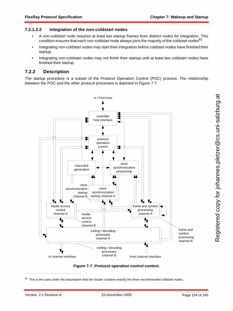
FlexRay Protocol Specification Chapter 7: Wakeup and Startup
Reg
iste
red
copy
for
joha
nnes
.ple
tzer
@cs
.uni
-sal
zbur
g.at
7.2.1.2.2 Integration of the non-coldstart nodes
• A non-coldstart node requires at least two startup frames from distinct nodes for integration. Thiscondition ensures that each non-coldstart node always joins the majority of the coldstart nodes81.
• Integrating non-coldstart nodes may start their integration before coldstart nodes have finished theirstartup.
• Integrating non-coldstart nodes may not finish their startup until at least two coldstart nodes havefinished their startup.
7.2.2 DescriptionThe startup procedure is a subset of the Protocol Operation Control (POC) process. The relationshipbetween the POC and the other protocol processes is depicted in Figure 7-7.
Figure 7-7: Protocol operation control context.
81 This is the case under the assumption that the cluster contains exactly the three recommended coldstart nodes.
frame and symbolprocessing
media accesscontrol
clocksynchronization
startup
macrotickgeneration
clocksynchronization
processing
protocoloperation
control
controllerhost interface
coding / decodingprocesseschannel A
frame and symbolprocessingchannel A
media accesscontrol
channel A
clocksynchronization
startup channel A
to channel interface from channel interface
to / from host
mediaaccesscontrolchannel B
coding / decodingprocesseschannel B
frame andsymbolprocessingchannel B
clocksynchronization
startupchannel B
Version 2.1 Revision A 15-December-2005 Page 154 of 245
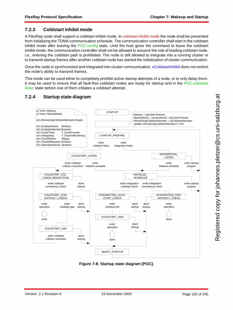
FlexRay Protocol Specification Chapter 7: Wakeup and Startup
Reg
iste
red
copy
for
joha
nnes
.ple
tzer
@cs
.uni
-sal
zbur
g.at
7.2.3 Coldstart inhibit modeA FlexRay node shall support a coldstart inhibit mode. In coldstart inhibit mode the node shall be preventedfrom initializing the TDMA communication schedule. The communication controller shall start in the coldstartinhibit mode after leaving the POC:config state. Until the host gives the command to leave the coldstartinhibit mode, the communication controller shall not be allowed to assume the role of leading coldstart node,i.e., entering the coldstart path is prohibited. The node is still allowed to integrate into a running cluster orto transmit startup frames after another coldstart node has started the initialization of cluster communication.
Once the node is synchronized and integrated into cluster communication, vColdstartInhibit does not restrictthe node's ability to transmit frames.
This mode can be used either to completely prohibit active startup attempts of a node, or to only delay them.It may be used to ensure that all fault-free coldstart nodes are ready for startup and in the POC:coldstartlisten state before one of them initiates a coldstart attempt.
7.2.4 Startup state diagram
Figure 7-8: Startup state diagram [POC].
µT timer tStartup;µT timer tStartupNoise;
dcl vRemainingColdstartAttempts Integer;
dcl zColdstartNoise Boolean;dcl zColdstartAborted Boolean;dcl zCycleTemp T_CycleCounter;dcl zIntegrating T_ChannelBoolArray;dcl zTwoSNSeen Integer;dcl zTwoSNRequired Boolean;dcl zStartupNoiseOut Boolean;
enter startupprepare
tStartup := pdListenTimeout;tStartupNoise := gListenNoise * pdListenTimeout;vRemainingColdstartAttempts := gColdstartAttempts;’update vRemainingColdstartAttempts in CHI’
STARTUP
INTEGRATION_LISTEN
COLDSTART_LISTEN
enter coldstartcollision resolution
enterinitialize schedule
COLDSTART_COL-LISION_RESOLUTION
enterinitialize schedule
abortstartup
enter coldstartconsistency check
COLDSTART_CON-SISTENCY_CHECK
abortstartup
entercoldstart gap
enteroperation
enter integrationconsistency check
enter startupprepare
INTEGRATION_CON-SISTENCY_CHECK
enteroperation
STARTUP_PREPARE
entercoldstart listen
enterintegration listen
done
COLDSTART_GAP
abortstartup
enter coldstartcollision resolution
ABORT_STARTUP
abortstartup
done
INITIALIZE_SCHEDULE
INTEGRATION_COLD-START_CHECK
COLDSTART_JOIN
enteroperation
abortstartup
done
enter integrationcoldstart check
entercoldstart join
abortstartup
Version 2.1 Revision A 15-December-2005 Page 155 of 245
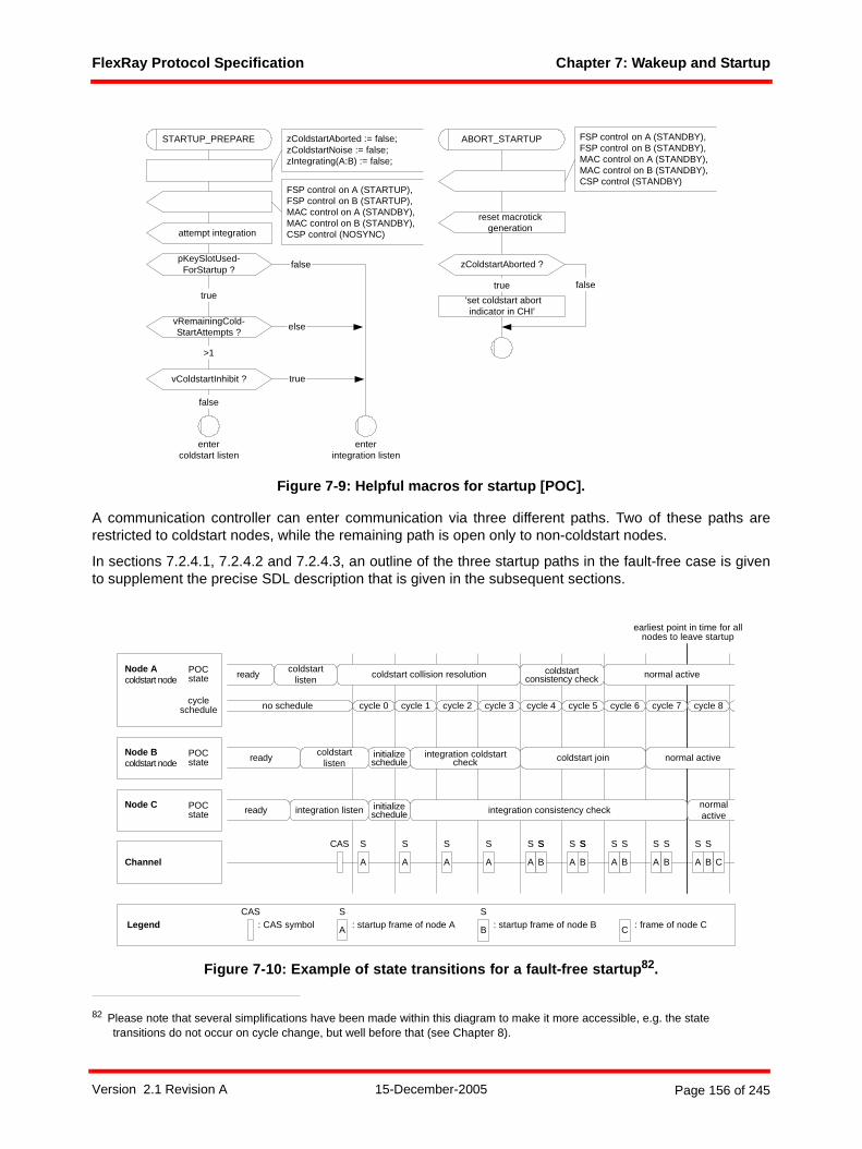
FlexRay Protocol Specification Chapter 7: Wakeup and Startup
Reg
iste
red
copy
for
joha
nnes
.ple
tzer
@cs
.uni
-sal
zbur
g.at
Figure 7-9: Helpful macros for startup [POC].
A communication controller can enter communication via three different paths. Two of these paths arerestricted to coldstart nodes, while the remaining path is open only to non-coldstart nodes.
In sections 7.2.4.1, 7.2.4.2 and 7.2.4.3, an outline of the three startup paths in the fault-free case is givento supplement the precise SDL description that is given in the subsequent sections.
Figure 7-10: Example of state transitions for a fault-free startup82.
82 Please note that several simplifications have been made within this diagram to make it more accessible, e.g. the state transitions do not occur on cycle change, but well before that (see Chapter 8).
vRemainingCold-StartAttempts ?
vColdstartInhibit ?
>1
false
false
true
attempt integration
STARTUP_PREPARE
enterintegration listen
ABORT_STARTUP FSP control on A (STANDBY),FSP control on B (STANDBY),MAC control on A (STANDBY),MAC control on B (STANDBY),CSP control (STANDBY)
zColdstartAborted := false;zColdstartNoise := false;zIntegrating(A:B) := false;
pKeySlotUsed-ForStartup ?
true
else
reset macrotickgeneration
FSP control on A (STARTUP),FSP control on B (STARTUP),MAC control on A (STANDBY),MAC control on B (STANDBY),CSP control (NOSYNC)
entercoldstart listen
zColdstartAborted ?
false
'set coldstart abortindicator in CHI'
true
POCstate
POCstate
no schedule
A
readycoldstart
listencoldstart collision resolution coldstart
consistency check normal active
ready
ready
coldstartlisten
integration listen
initializeschedule
initializeschedule
integration coldstartcheck
integration consistency check
coldstart join
normalactive
normal active
A A A A A A A AB B B B B C
Node Acoldstart node
Node Bcoldstart node
Node C
Channel
CAS
cycle 0 cycle 1 cycle 2 cycle 3 cycle 4 cycle 5 cycle 6 cycle 7 cycle 8
POCstate
cycleschedule
S S S S SS SS SS S S S S
LegendCAS
: CAS symbol A
S: startup frame of node A B
S: startup frame of node B C : frame of node C
earliest point in time for allnodes to leave startup
SS
Version 2.1 Revision A 15-December-2005 Page 156 of 245
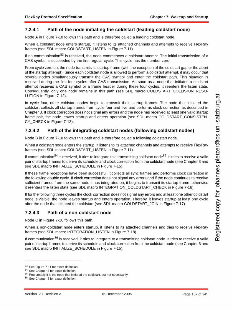
FlexRay Protocol Specification Chapter 7: Wakeup and Startup
Reg
iste
red
copy
for
joha
nnes
.ple
tzer
@cs
.uni
-sal
zbur
g.at
7.2.4.1 Path of the node initiating the coldstart (leading coldstart node)
Node A in Figure 7-10 follows this path and is therefore called a leading coldstart node.
When a coldstart node enters startup, it listens to its attached channels and attempts to receive FlexRayframes (see SDL macro COLDSTART_LISTEN in Figure 7-11).
If no communication83 is received, the node commences a coldstart attempt. The initial transmission of aCAS symbol is succeeded by the first regular cycle. This cycle has the number zero.
From cycle zero on, the node transmits its startup frame (with the exception of the coldstart gap or the abortof the startup attempt). Since each coldstart node is allowed to perform a coldstart attempt, it may occur thatseveral nodes simultaneously transmit the CAS symbol and enter the coldstart path. This situation isresolved during the first four cycles after CAS transmission. As soon as a node that initiates a coldstartattempt receives a CAS symbol or a frame header during these four cycles, it reenters the listen state.Consequently, only one node remains in this path (see SDL macro COLDSTART_COLLISION_RESO-LUTION in Figure 7-12).
In cycle four, other coldstart nodes begin to transmit their startup frames. The node that initiated thecoldstart collects all startup frames from cycle four and five and performs clock correction as described inChapter 8. If clock correction does not signal any errors and the node has received at least one valid startupframe pair, the node leaves startup and enters operation (see SDL macro COLDSTART_CONSISTEN-CY_CHECK in Figure 7-13).
7.2.4.2 Path of the integrating coldstart nodes (following coldstart nodes)
Node B in Figure 7-10 follows this path and is therefore called a following coldstart node.
When a coldstart node enters the startup, it listens to its attached channels and attempts to receive FlexRayframes (see SDL macro COLDSTART_LISTEN in Figure 7-11).
If communication84 is received, it tries to integrate to a transmitting coldstart node85. It tries to receive a validpair of startup frames to derive its schedule and clock correction from the coldstart node (see Chapter 8 andsee SDL macro INITIALIZE_SCHEDULE in Figure 7-15).
If these frame receptions have been successful, it collects all sync frames and performs clock correction inthe following double cycle. If clock correction does not signal any errors and if the node continues to receivesufficient frames from the same node it has integrated on, it begins to transmit its startup frame; otherwiseit reenters the listen state (see SDL macro INTEGRATION_COLDSTART_CHECK in Figure 7-16).
If for the following three cycles the clock correction does not signal any errors and at least one other coldstartnode is visible, the node leaves startup and enters operation. Thereby, it leaves startup at least one cycleafter the node that initiated the coldstart (see SDL macro COLDSTART_JOIN in Figure 7-17).
7.2.4.3 Path of a non-coldstart node
Node C in Figure 7-10 follows this path.
When a non-coldstart node enters startup, it listens to its attached channels and tries to receive FlexRayframes (see SDL macro INTEGRATION_LISTEN in Figure 7-18).
If communication86 is received, it tries to integrate to a transmitting coldstart node. It tries to receive a validpair of startup frames to derive its schedule and clock correction from the coldstart node (see Chapter 8 andsee SDL macro INITIALIZE_SCHEDULE in Figure 7-15).
83 See Figure 7-11 for exact definition.84 See Chapter 8 for exact definition.85 Presumably it is the node that initiated the coldstart, but not necessarily.86 See Chapter 8 for exact definition.
Version 2.1 Revision A 15-December-2005 Page 157 of 245

FlexRay Protocol Specification Chapter 7: Wakeup and Startup
Reg
iste
red
copy
for
joha
nnes
.ple
tzer
@cs
.uni
-sal
zbur
g.at
In the following double cycles, it tries to find at least two coldstart nodes that transmit startup frames that fitinto its own schedule. If this fails, or if clock correction signals an error, the node aborts the integrationattempt and tries anew.
After receiving valid startup frames pairs for two consecutive double cycles from at least two coldstartnodes, the node leaves startup and enters operation. Thereby, it leaves startup at least two cycles after thenode that initiated the coldstart. That means that all nodes of the cluster can leave startup at the end of cycle7, just before entering cycle 8 (see Figure 7-10 and SDL macro INTEGRATION_CONSISTENCY_CHECKin Figure 7-19).
Version 2.1 Revision A 15-December-2005 Page 158 of 245
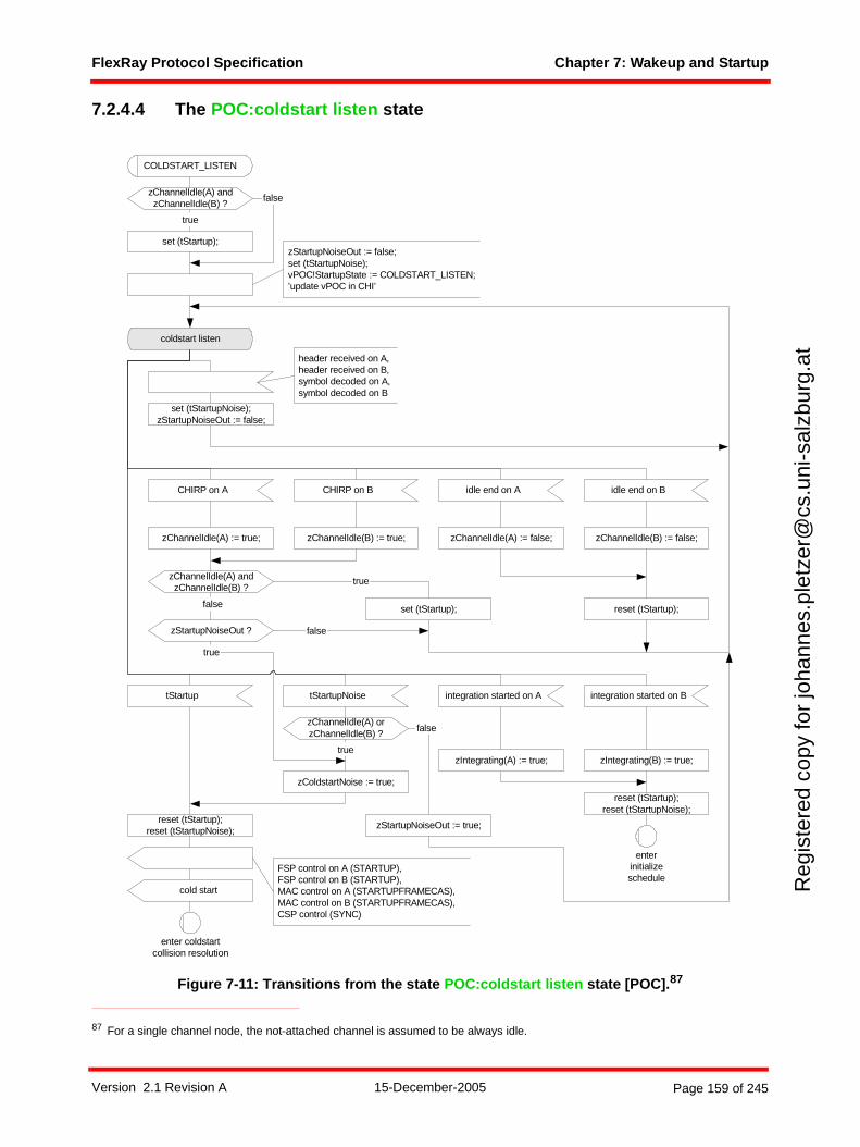
FlexRay Protocol Specification Chapter 7: Wakeup and Startup
Reg
iste
red
copy
for
joha
nnes
.ple
tzer
@cs
.uni
-sal
zbur
g.at
7.2.4.4 The POC:coldstart listen state
Figure 7-11: Transitions from the state POC:coldstart listen state [POC].87
87 For a single channel node, the not-attached channel is assumed to be always idle.
coldstart listen
set (tStartupNoise);zStartupNoiseOut := false;
reset (tStartup);false set (tStartup);
true
tStartup tStartupNoise integration started on A
reset (tStartup);reset (tStartupNoise);
reset (tStartup);reset (tStartupNoise);
zChannelIdle(A) andzChannelIdle(B) ?
false
set (tStartup);
true
COLDSTART_LISTEN
enter coldstartcollision resolution
enterinitializeschedule
CHIRP on A idle end on ACHIRP on B idle end on B
zChannelIdle(A) := true; zChannelIdle(A) := false;zChannelIdle(B) := true; zChannelIdle(B) := false;
zChannelIdle(A) andzChannelIdle(B) ?
FSP control on A (STARTUP),FSP control on B (STARTUP),MAC control on A (STARTUPFRAMECAS),MAC control on B (STARTUPFRAMECAS),CSP control (SYNC)
integration started on B
zIntegrating(A) := true; zIntegrating(B) := true;
cold start
zColdstartNoise := true;
true
zStartupNoiseOut := false;set (tStartupNoise);vPOC!StartupState := COLDSTART_LISTEN;’update vPOC in CHI’
zStartupNoiseOut ? false
true
header received on A,header received on B,symbol decoded on A,symbol decoded on B
zChannelIdle(A) orzChannelIdle(B) ? false
zStartupNoiseOut := true;
Version 2.1 Revision A 15-December-2005 Page 159 of 245
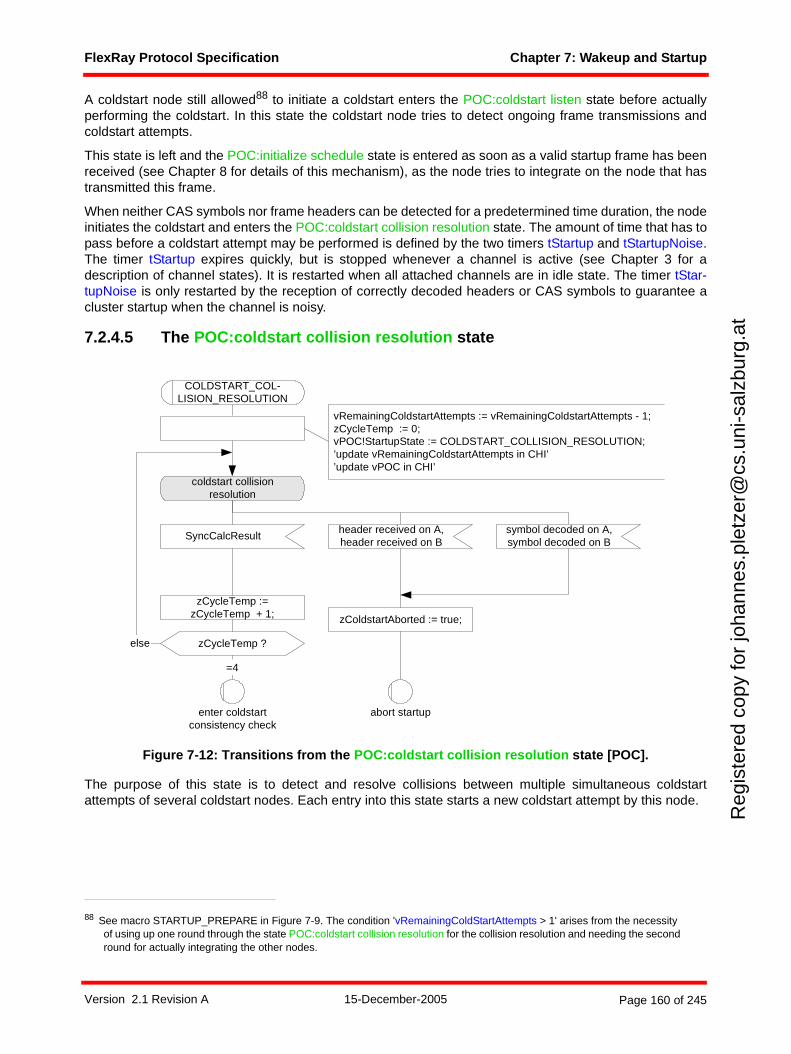
FlexRay Protocol Specification Chapter 7: Wakeup and Startup
Reg
iste
red
copy
for
joha
nnes
.ple
tzer
@cs
.uni
-sal
zbur
g.at
A coldstart node still allowed88 to initiate a coldstart enters the POC:coldstart listen state before actuallyperforming the coldstart. In this state the coldstart node tries to detect ongoing frame transmissions andcoldstart attempts.
This state is left and the POC:initialize schedule state is entered as soon as a valid startup frame has beenreceived (see Chapter 8 for details of this mechanism), as the node tries to integrate on the node that hastransmitted this frame.
When neither CAS symbols nor frame headers can be detected for a predetermined time duration, the nodeinitiates the coldstart and enters the POC:coldstart collision resolution state. The amount of time that has topass before a coldstart attempt may be performed is defined by the two timers tStartup and tStartupNoise.The timer tStartup expires quickly, but is stopped whenever a channel is active (see Chapter 3 for adescription of channel states). It is restarted when all attached channels are in idle state. The timer tStar-tupNoise is only restarted by the reception of correctly decoded headers or CAS symbols to guarantee acluster startup when the channel is noisy.
7.2.4.5 The POC:coldstart collision resolution state
Figure 7-12: Transitions from the POC:coldstart collision resolution state [POC].
The purpose of this state is to detect and resolve collisions between multiple simultaneous coldstartattempts of several coldstart nodes. Each entry into this state starts a new coldstart attempt by this node.
88 See macro STARTUP_PREPARE in Figure 7-9. The condition 'vRemainingColdStartAttempts > 1' arises from the necessity of using up one round through the state POC:coldstart collision resolution for the collision resolution and needing the second round for actually integrating the other nodes.
coldstart collisionresolution
zColdstartAborted := true;
symbol decoded on A,symbol decoded on B
header received on A,header received on B
SyncCalcResult
zCycleTemp :=zCycleTemp + 1;
zCycleTemp ?else
=4
vRemainingColdstartAttempts := vRemainingColdstartAttempts - 1;zCycleTemp := 0;vPOC!StartupState := COLDSTART_COLLISION_RESOLUTION;’update vRemainingColdstartAttempts in CHI’’update vPOC in CHI’
COLDSTART_COL-LISION_RESOLUTION
enter coldstartconsistency check
abort startup
Version 2.1 Revision A 15-December-2005 Page 160 of 245
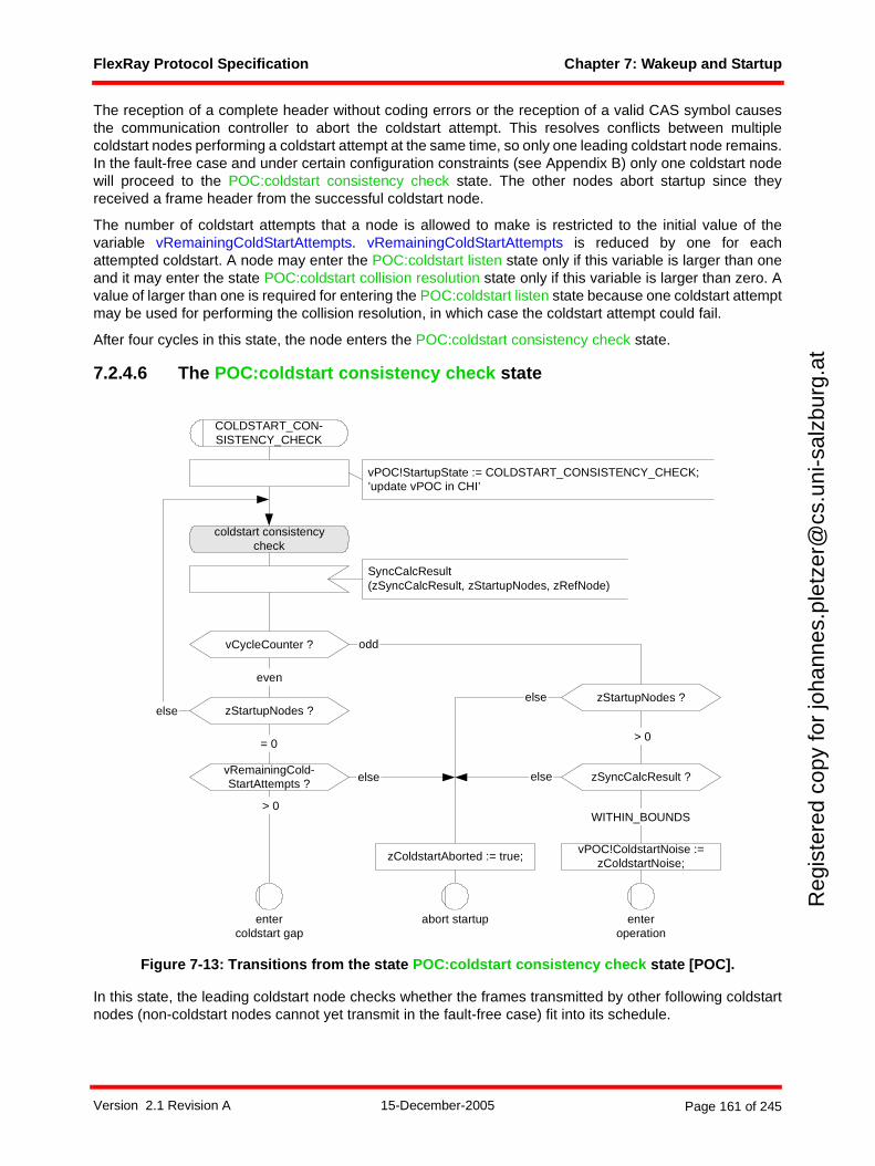
FlexRay Protocol Specification Chapter 7: Wakeup and Startup
Reg
iste
red
copy
for
joha
nnes
.ple
tzer
@cs
.uni
-sal
zbur
g.at
The reception of a complete header without coding errors or the reception of a valid CAS symbol causesthe communication controller to abort the coldstart attempt. This resolves conflicts between multiplecoldstart nodes performing a coldstart attempt at the same time, so only one leading coldstart node remains.In the fault-free case and under certain configuration constraints (see Appendix B) only one coldstart nodewill proceed to the POC:coldstart consistency check state. The other nodes abort startup since theyreceived a frame header from the successful coldstart node.
The number of coldstart attempts that a node is allowed to make is restricted to the initial value of thevariable vRemainingColdStartAttempts. vRemainingColdStartAttempts is reduced by one for eachattempted coldstart. A node may enter the POC:coldstart listen state only if this variable is larger than oneand it may enter the state POC:coldstart collision resolution state only if this variable is larger than zero. Avalue of larger than one is required for entering the POC:coldstart listen state because one coldstart attemptmay be used for performing the collision resolution, in which case the coldstart attempt could fail.
After four cycles in this state, the node enters the POC:coldstart consistency check state.
7.2.4.6 The POC:coldstart consistency check state
Figure 7-13: Transitions from the state POC:coldstart consistency check state [POC].
In this state, the leading coldstart node checks whether the frames transmitted by other following coldstartnodes (non-coldstart nodes cannot yet transmit in the fault-free case) fit into its schedule.
coldstart consistencycheck
> 0= 0
else
odd
even
vRemainingCold-StartAttempts ?
> 0
else
zStartupNodes ?
vCycleCounter ?
zStartupNodes ?
else
else
enteroperation
COLDSTART_CON-SISTENCY_CHECK
entercoldstart gap
abort startup
zColdstartAborted := true;
SyncCalcResult(zSyncCalcResult, zStartupNodes, zRefNode)
zSyncCalcResult ?
WITHIN_BOUNDS
vPOC!ColdstartNoise :=zColdstartNoise;
vPOC!StartupState := COLDSTART_CONSISTENCY_CHECK;’update vPOC in CHI’
Version 2.1 Revision A 15-December-2005 Page 161 of 245
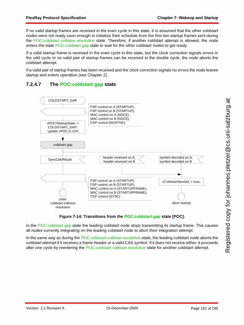
FlexRay Protocol Specification Chapter 7: Wakeup and Startup
Reg
iste
red
copy
for
joha
nnes
.ple
tzer
@cs
.uni
-sal
zbur
g.at
If no valid startup frames are received in the even cycle in this state, it is assumed that the other coldstartnodes were not ready soon enough to initialize their schedule from the first two startup frames sent duringthe POC:coldstart collision resolution state. Therefore, if another coldstart attempt is allowed, the nodeenters the state POC:coldstart gap state to wait for the other coldstart nodes to get ready.
If a valid startup frame is received in the even cycle in this state, but the clock correction signals errors inthe odd cycle or no valid pair of startup frames can be received in the double cycle, the node aborts thecoldstart attempt.
If a valid pair of startup frames has been received and the clock correction signals no errors the node leavesstartup and enters operation (see Chapter 2).
7.2.4.7 The POC:coldstart gap state
Figure 7-14: Transitions from the POC:coldstart gap state [POC].
In the POC:coldstart gap state the leading coldstart node stops transmitting its startup frame. This causesall nodes currently integrating on the leading coldstart node to abort their integration attempt.
In the same way as during the POC:coldstart collision resolution state, the leading coldstart node aborts thecoldstart attempt if it receives a frame header or a valid CAS symbol. If it does not receive either, it proceedsafter one cycle by reentering the POC:coldstart collision resolution state for another coldstart attempt.
coldstart gap
zColdstartAborted := true;
header received on A,header received on B
SyncCalcResult
entercoldstart collision
resolutionabort startup
COLDSTART_GAP
FSP control on A (STARTUP),FSP control on B (STARTUP),MAC control on A (STARTUPFRAME),MAC control on B (STARTUPFRAME),CSP control (SYNC)
FSP control on A (STARTUP),FSP control on B (STARTUP),MAC control on A (NOCE) ,MAC control on B (NOCE),CSP control (NOSYNC)
symbol decoded on A,symbol decoded on B
vPOC!StartupState :=COLDSTART_GAP;’update vPOC in CHI’
Version 2.1 Revision A 15-December-2005 Page 162 of 245
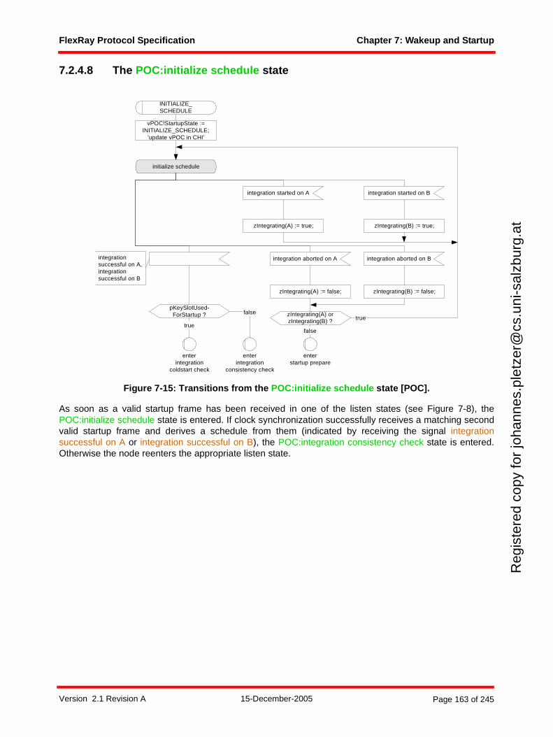
FlexRay Protocol Specification Chapter 7: Wakeup and Startup
Reg
iste
red
copy
for
joha
nnes
.ple
tzer
@cs
.uni
-sal
zbur
g.at
7.2.4.8 The POC:initialize schedule state
Figure 7-15: Transitions from the POC:initialize schedule state [POC].
As soon as a valid startup frame has been received in one of the listen states (see Figure 7-8), thePOC:initialize schedule state is entered. If clock synchronization successfully receives a matching secondvalid startup frame and derives a schedule from them (indicated by receiving the signal integrationsuccessful on A or integration successful on B), the POC:integration consistency check state is entered.Otherwise the node reenters the appropriate listen state.
initialize schedule
integration aborted on A
INITIALIZE_SCHEDULE
integration aborted on B
enterstartup prepare
integration started on A integration started on B
zIntegrating(B) := true;zIntegrating(A) := true;
zIntegrating(B) := false;zIntegrating(A) := false;
zIntegrating(A) orzIntegrating(B) ? true
false
false
enterintegration
consistency check
integrationsuccessful on A,integrationsuccessful on B
pKeySlotUsed-ForStartup ?
true
enterintegration
coldstart check
vPOC!StartupState :=INITIALIZE_SCHEDULE;
’update vPOC in CHI’
Version 2.1 Revision A 15-December-2005 Page 163 of 245
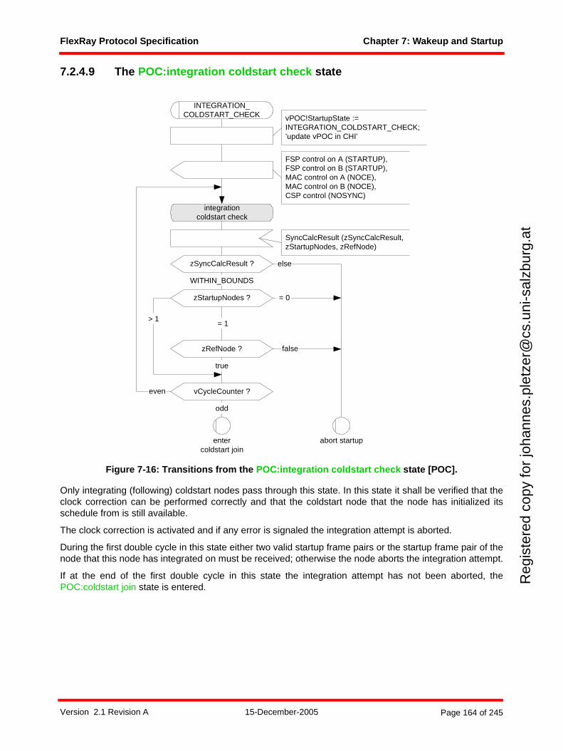
FlexRay Protocol Specification Chapter 7: Wakeup and Startup
Reg
iste
red
copy
for
joha
nnes
.ple
tzer
@cs
.uni
-sal
zbur
g.at
7.2.4.9 The POC:integration coldstart check state
Figure 7-16: Transitions from the POC:integration coldstart check state [POC].
Only integrating (following) coldstart nodes pass through this state. In this state it shall be verified that theclock correction can be performed correctly and that the coldstart node that the node has initialized itsschedule from is still available.
The clock correction is activated and if any error is signaled the integration attempt is aborted.
During the first double cycle in this state either two valid startup frame pairs or the startup frame pair of thenode that this node has integrated on must be received; otherwise the node aborts the integration attempt.
If at the end of the first double cycle in this state the integration attempt has not been aborted, thePOC:coldstart join state is entered.
integrationcoldstart check
else
odd
vCycleCounter ?even
zStartupNodes ?
true
= 0
entercoldstart join
abort startup
INTEGRATION_COLDSTART_CHECK
FSP control on A (STARTUP),FSP control on B (STARTUP),MAC control on A (NOCE),MAC control on B (NOCE),CSP control (NOSYNC)
zRefNode ?
= 1
false
> 1
WITHIN_BOUNDS
zSyncCalcResult ?
SyncCalcResult (zSyncCalcResult,zStartupNodes, zRefNode)
vPOC!StartupState :=INTEGRATION_COLDSTART_CHECK;’update vPOC in CHI’
Version 2.1 Revision A 15-December-2005 Page 164 of 245
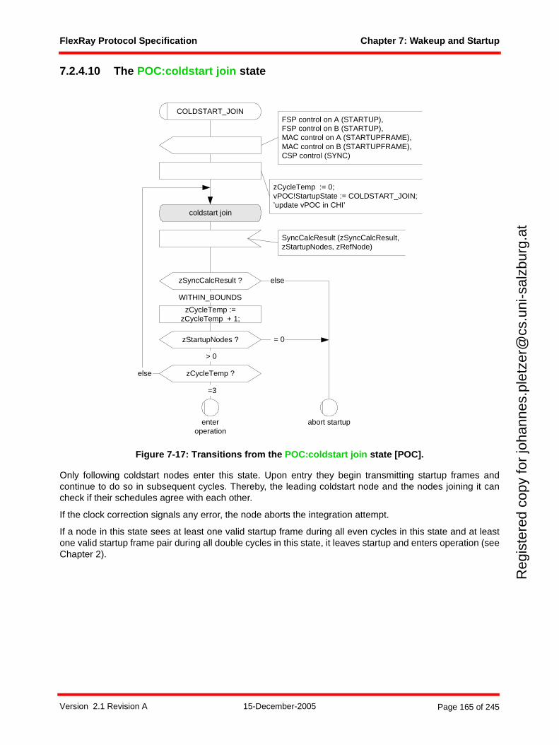
FlexRay Protocol Specification Chapter 7: Wakeup and Startup
Reg
iste
red
copy
for
joha
nnes
.ple
tzer
@cs
.uni
-sal
zbur
g.at
7.2.4.10 The POC:coldstart join state
Figure 7-17: Transitions from the POC:coldstart join state [POC].
Only following coldstart nodes enter this state. Upon entry they begin transmitting startup frames andcontinue to do so in subsequent cycles. Thereby, the leading coldstart node and the nodes joining it cancheck if their schedules agree with each other.
If the clock correction signals any error, the node aborts the integration attempt.
If a node in this state sees at least one valid startup frame during all even cycles in this state and at leastone valid startup frame pair during all double cycles in this state, it leaves startup and enters operation (seeChapter 2).
coldstart join
zCycleTemp ?else
=3
= 0zStartupNodes ?
> 0
zCycleTemp :=zCycleTemp + 1;
else
enteroperation
COLDSTART_JOIN
abort startup
FSP control on A (STARTUP),FSP control on B (STARTUP),MAC control on A (STARTUPFRAME),MAC control on B (STARTUPFRAME),CSP control (SYNC)
WITHIN_BOUNDS
zSyncCalcResult ?
SyncCalcResult (zSyncCalcResult,zStartupNodes, zRefNode)
zCycleTemp := 0;vPOC!StartupState := COLDSTART_JOIN;’update vPOC in CHI’
Version 2.1 Revision A 15-December-2005 Page 165 of 245
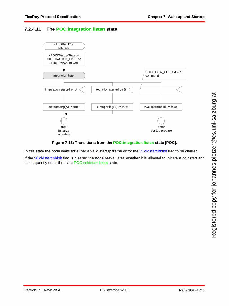
FlexRay Protocol Specification Chapter 7: Wakeup and Startup
Reg
iste
red
copy
for
joha
nnes
.ple
tzer
@cs
.uni
-sal
zbur
g.at
7.2.4.11 The POC:integration listen state
Figure 7-18: Transitions from the POC:integration listen state [POC].
In this state the node waits for either a valid startup frame or for the vColdstartInhibit flag to be cleared.
If the vColdstartInhibit flag is cleared the node reevaluates whether it is allowed to initiate a coldstart andconsequently enter the state POC:coldstart listen state.
integration listen
integration started on A
INTEGRATION_LISTEN
enterstartup prepare
enterinitializeschedule
integration started on B
zIntegrating(A) := true; zIntegrating(B) := true; vColdstartInhibit := false;
CHI ALLOW_COLDSTARTcommand
vPOC!StartupState :=INTEGRATION_LISTEN;
’update vPOC in CHI’
Version 2.1 Revision A 15-December-2005 Page 166 of 245
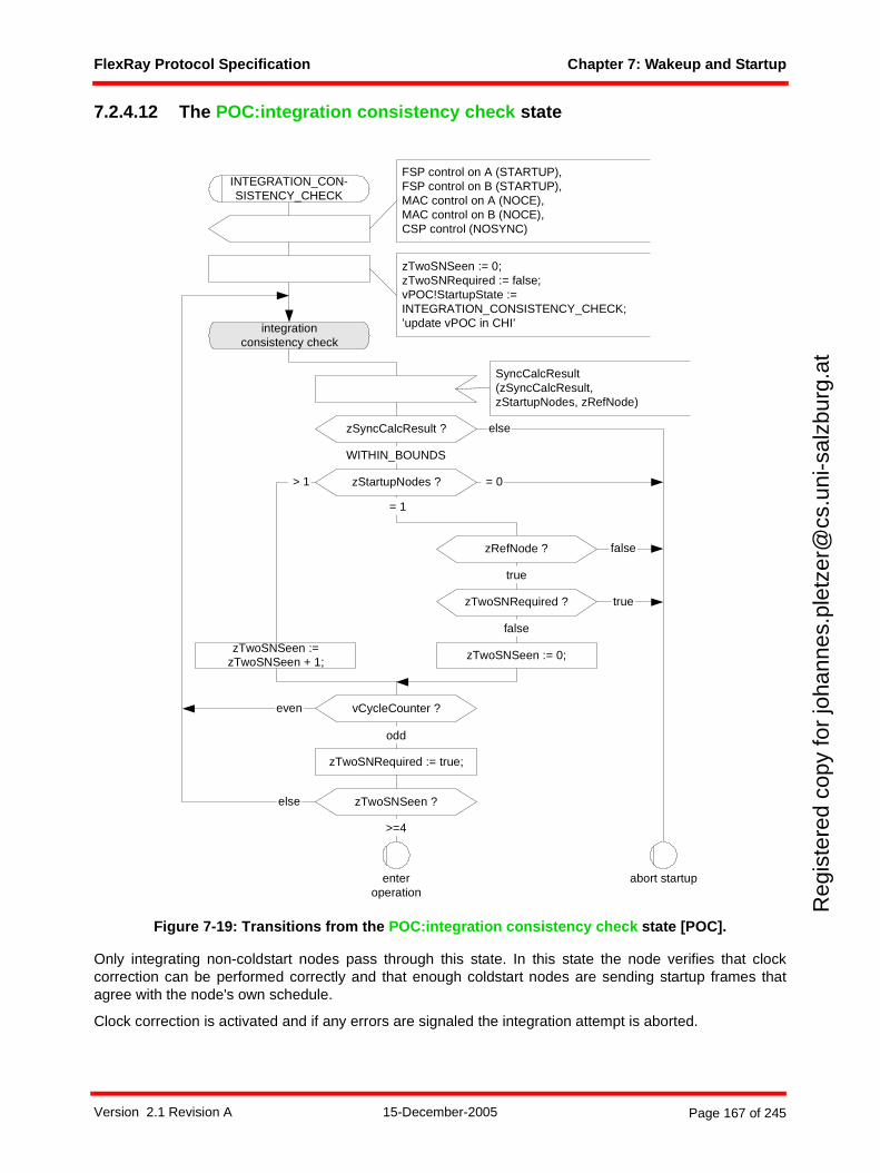
FlexRay Protocol Specification Chapter 7: Wakeup and Startup
Reg
iste
red
copy
for
joha
nnes
.ple
tzer
@cs
.uni
-sal
zbur
g.at
7.2.4.12 The POC:integration consistency check state
Figure 7-19: Transitions from the POC:integration consistency check state [POC].
Only integrating non-coldstart nodes pass through this state. In this state the node verifies that clockcorrection can be performed correctly and that enough coldstart nodes are sending startup frames thatagree with the node's own schedule.
Clock correction is activated and if any errors are signaled the integration attempt is aborted.
integrationconsistency check
else
odd
vCycleCounter ?even
enteroperation
zTwoSNSeen := 0;zTwoSNRequired := false;vPOC!StartupState :=INTEGRATION_CONSISTENCY_CHECK;’update vPOC in CHI’
zStartupNodes ?
zTwoSNSeen :=zTwoSNSeen + 1;
zTwoSNSeen := 0;
> 1
= 1
>=4
else zTwoSNSeen ?
zTwoSNRequired ?
zTwoSNRequired := true;
= 0
abort startup
INTEGRATION_CON-SISTENCY_CHECK
FSP control on A (STARTUP),FSP control on B (STARTUP),MAC control on A (NOCE),MAC control on B (NOCE),CSP control (NOSYNC)
false
true
zRefNode ?
true
false
WITHIN_BOUNDS
zSyncCalcResult ?
SyncCalcResult(zSyncCalcResult,zStartupNodes, zRefNode)
Version 2.1 Revision A 15-December-2005 Page 167 of 245
FlexRay Protocol Specification Chapter 7: Wakeup and Startup
Reg
iste
red
copy
for
joha
nnes
.ple
tzer
@cs
.uni
-sal
zbur
g.at
During the first even cycle in this state, either two valid startup frames or the startup frame of the node thatthis node has integrated on must be received; otherwise the node aborts the integration attempt.
During the first double cycle in this state, either two valid startup frame pairs or the startup frame pair of thenode that this node has integrated on must be received; otherwise the node aborts the integration attempt.
After the first double cycle, if less than two valid startup frames are received within an even cycle, or lessthan two valid startup frame pairs are received within a double cycle, the startup attempt is aborted.
Nodes in this state need to see two valid startup frame pairs for two consecutive double cycles each to beallowed to leave startup and enter operation (see Chapter 2). Consequently, they leave startup at least onedouble cycle after the node that initiated the coldstart and only at the end of a cycle with an odd cyclenumber.
Version 2.1 Revision A 15-December-2005 Page 168 of 245
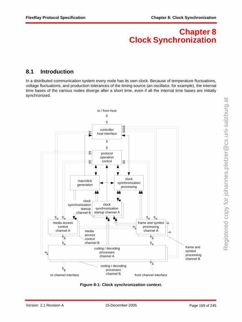
FlexRay Protocol Specification Chapter 8: Clock Synchronization
Reg
iste
red
copy
for
joha
nnes
.ple
tzer
@cs
.uni
-sal
zbur
g.at
Chapter 8Clock Synchronization
8.1 Introduction
In a distributed communication system every node has its own clock. Because of temperature fluctuations,voltage fluctuations, and production tolerances of the timing source (an oscillator, for example), the internaltime bases of the various nodes diverge after a short time, even if all the internal time bases are initiallysynchronized.
Figure 8-1: Clock synchronization context.
frame and symbolprocessing
media accesscontrol
clocksynchronization
startup
macrotickgeneration
clocksynchronization
processing
protocoloperation
control
controllerhost interface
coding / decodingprocesseschannel A
frame and symbolprocessingchannel A
media accesscontrol
channel A
clocksynchronization
startup channel A
to channel interface from channel interface
to / from host
mediaaccesscontrolchannel B
coding / decodingprocesseschannel B
frame andsymbolprocessingchannel B
clocksynchronization
startupchannel B
Version 2.1 Revision A 15-December-2005 Page 169 of 245
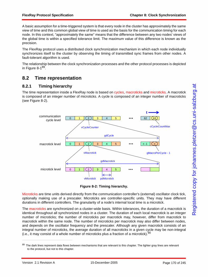
FlexRay Protocol Specification Chapter 8: Clock Synchronization
Reg
iste
red
copy
for
joha
nnes
.ple
tzer
@cs
.uni
-sal
zbur
g.at
A basic assumption for a time-triggered system is that every node in the cluster has approximately the sameview of time and this common global view of time is used as the basis for the communication timing for eachnode. In this context, "approximately the same" means that the difference between any two nodes' views ofthe global time is within a specified tolerance limit. The maximum value of this difference is known as theprecision.
The FlexRay protocol uses a distributed clock synchronization mechanism in which each node individuallysynchronizes itself to the cluster by observing the timing of transmitted sync frames from other nodes. Afault-tolerant algorithm is used.
The relationship between the clock synchronization processes and the other protocol processes is depictedin Figure 8-189.
8.2 Time representation
8.2.1 Timing hierarchyThe time representation inside a FlexRay node is based on cycles, macroticks and microticks. A macrotickis composed of an integer number of microticks. A cycle is composed of an integer number of macroticks(see Figure 8-2).
Figure 8-2: Timing hierarchy.
Microticks are time units derived directly from the communication controller's (external) oscillator clock tick,optionally making use of a prescaler. Microticks are controller-specific units. They may have differentdurations in different controllers. The granularity of a node's internal local time is a microtick.
The macroticks are synchronized on a cluster-wide basis. Within tolerances, the duration of a macrotick isidentical throughout all synchronized nodes in a cluster. The duration of each local macrotick is an integernumber of microticks; the number of microticks per macrotick may, however, differ from macrotick tomacrotick within the same node. The number of microticks per macrotick may also differ between nodes,and depends on the oscillator frequency and the prescaler. Although any given macrotick consists of anintegral number of microticks, the average duration of all macroticks in a given cycle may be non-integral(i.e., it may consist of a whole number of microticks plus a fraction of a microtick).90
89 The dark lines represent data flows between mechanisms that are relevant to this chapter. The lighter gray lines are relevant to the protocol, but not to this chapter.
0 1 2 3 4 5 62 63
0 1 2 3 4 5 n -1 n...
...
0 1 2 3 4 5 ...
gdCycle
gdMacrotick
pdMicrotick
cCycleCountMax
gMacroPerCycle - 1
communicationcycle level
macrotick level
microtick level
t
vCycleCounter
vMacrotick
vMicrotick
Version 2.1 Revision A 15-December-2005 Page 170 of 245
FlexRay Protocol Specification Chapter 8: Clock Synchronization
Reg
iste
red
copy
for
joha
nnes
.ple
tzer
@cs
.uni
-sal
zbur
g.at
A cycle consists of an integer number of macroticks. The number of macroticks per cycle shall be identicalin all nodes in a cluster, and remains the same from cycle to cycle. At any given time all nodes should havethe same cycle number (except at cycle boundaries as a result of imperfect synchronization in the cluster).91
8.2.2 Global and local timeThe global time of a cluster is the general common understanding of time inside the cluster. The FlexRayprotocol does not have an absolute or reference global time; every node has its own local view of the globaltime.
The local time is the time of the node's clock and is represented by the variables vCycleCounter, vMacrotick,and vMicrotick. vCycleCounter and vMacrotick shall be visible to the application. The update ofvCycleCounter at the beginning of a cycle shall be atomic with the update of vMacrotick.92
The local time is based on the local view of the global time. Every node uses the clock synchronizationalgorithm to attempt to adapt its local view of time to the global time.
The precision of a cluster is the maximum difference between the local times of any two synchronized nodesin the cluster.
8.2.3 Parameters and variablesvCycleCounter is the (controller-local) cycle number and is incremented by one at the beginning of eachcommunication cycle. vCycleCounter ranges from 0 to cCycleCountMax. When cCycleCountMax isreached, the cycle counter vCycleCounter shall be reset to zero in the next communication cycle instead ofbeing incremented.
vMacrotick represents the current value of the (controller-local) macrotick and ranges from 0 to (gMacro-PerCycle - 1). gMacroPerCycle defines the (integer) number of macroticks per cycle.
vMicrotick represents the current value of the (controller-local) microtick.syntype
T_Macrotick = Integerendsyntype;syntype
T_Microtick = Integerendsyntype;
Definition 8-1: Formal definition of T_Macrotick and T_Microtick.
The FlexRay "timing" will be configured by:
• gMacroPerCycle and
• two of the three parameters pMicroPerCycle, gdCycle and pdMicrotick. pMicroPerCycle is the nodespecific number of microticks per cycle, gdCycle is the cluster wide duration of one communicationcycle, and pdMicrotick is the node specific duration of one microtick. The relation between thesethree parameters is:
pMicroPerCycle = round(gdCycle / pdMicrotick)
90 This is true even for the nominal (uncorrected) average duration of a macrotick (for example 6000 microticks distributed over 137 macroticks).
91 The cycle number discrepancy is at most one, and lasts no longer than the precision of the system.92 An atomic action is an action where no interruption is possible.
Version 2.1 Revision A 15-December-2005 Page 171 of 245
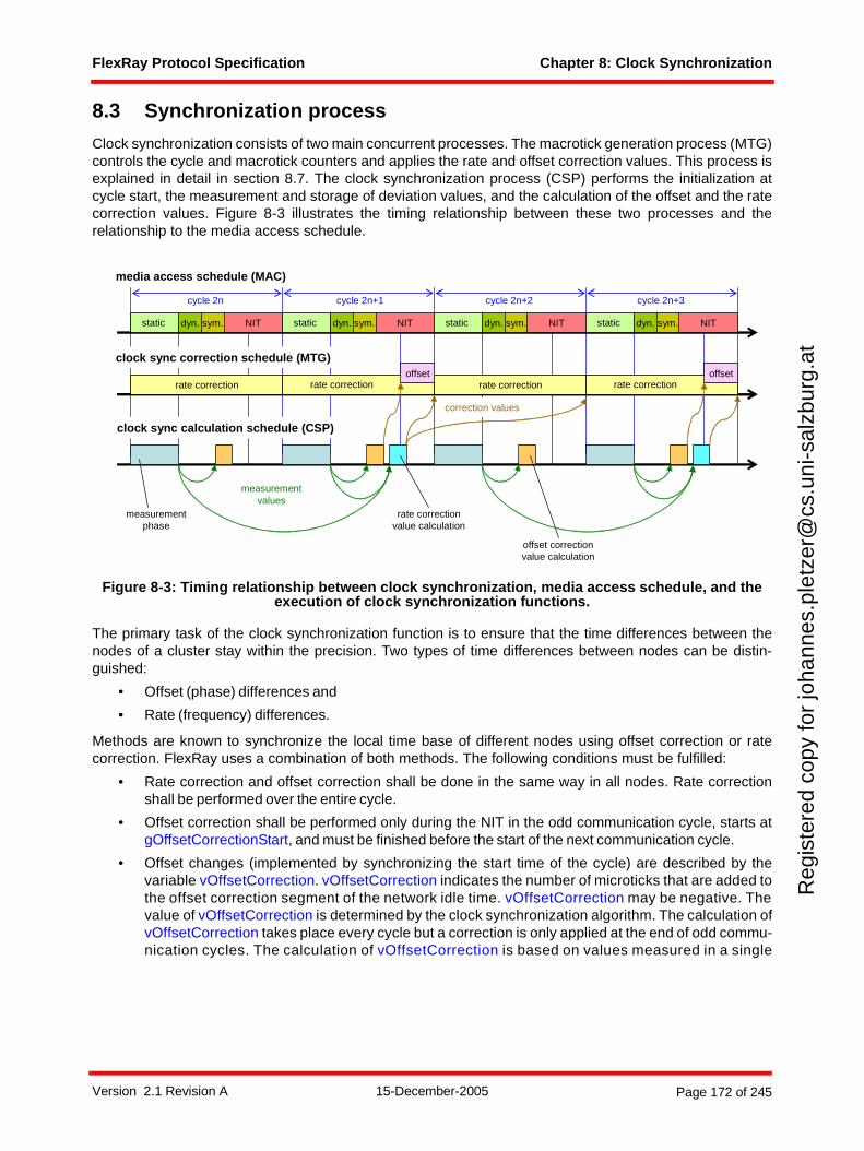
FlexRay Protocol Specification Chapter 8: Clock Synchronization
Reg
iste
red
copy
for
joha
nnes
.ple
tzer
@cs
.uni
-sal
zbur
g.at
8.3 Synchronization process
Clock synchronization consists of two main concurrent processes. The macrotick generation process (MTG)controls the cycle and macrotick counters and applies the rate and offset correction values. This process isexplained in detail in section 8.7. The clock synchronization process (CSP) performs the initialization atcycle start, the measurement and storage of deviation values, and the calculation of the offset and the ratecorrection values. Figure 8-3 illustrates the timing relationship between these two processes and therelationship to the media access schedule.
Figure 8-3: Timing relationship between clock synchronization, media access schedule, and the execution of clock synchronization functions.
The primary task of the clock synchronization function is to ensure that the time differences between thenodes of a cluster stay within the precision. Two types of time differences between nodes can be distin-guished:
• Offset (phase) differences and
• Rate (frequency) differences.
Methods are known to synchronize the local time base of different nodes using offset correction or ratecorrection. FlexRay uses a combination of both methods. The following conditions must be fulfilled:
• Rate correction and offset correction shall be done in the same way in all nodes. Rate correctionshall be performed over the entire cycle.
• Offset correction shall be performed only during the NIT in the odd communication cycle, starts atgOffsetCorrectionStart, and must be finished before the start of the next communication cycle.
• Offset changes (implemented by synchronizing the start time of the cycle) are described by thevariable vOffsetCorrection. vOffsetCorrection indicates the number of microticks that are added tothe offset correction segment of the network idle time. vOffsetCorrection may be negative. Thevalue of vOffsetCorrection is determined by the clock synchronization algorithm. The calculation ofvOffsetCorrection takes place every cycle but a correction is only applied at the end of odd commu-nication cycles. The calculation of vOffsetCorrection is based on values measured in a single
media access schedule (MAC)
clock sync correction schedule (MTG)
clock sync calculation schedule (CSP)
rate correction rate correction
NITstatic
rate correction rate correctionoffset
measurementphase
dyn. static static static
rate correction value calculation
offset correction value calculation
cycle 2n cycle 2n+1 cycle 2n+2 cycle 2n+3
measurementvalues
correction values
offset
dyn. dyn. dyn.sym. NITsym. NITsym. NITsym.
Version 2.1 Revision A 15-December-2005 Page 172 of 245
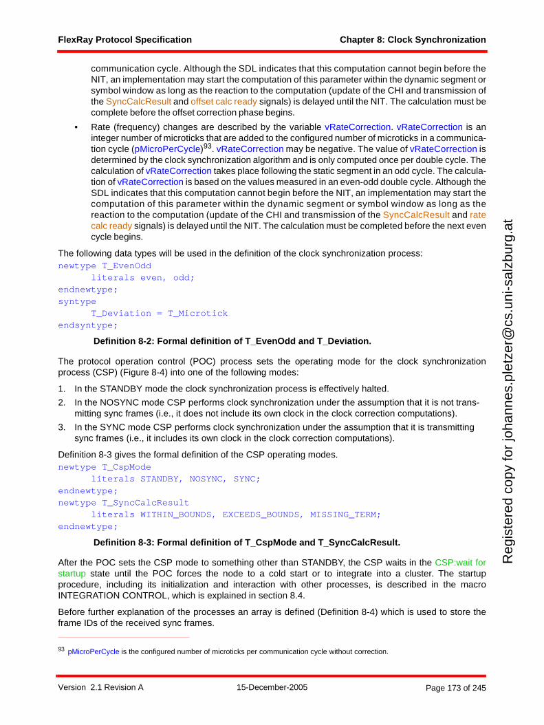
FlexRay Protocol Specification Chapter 8: Clock Synchronization
Reg
iste
red
copy
for
joha
nnes
.ple
tzer
@cs
.uni
-sal
zbur
g.at
communication cycle. Although the SDL indicates that this computation cannot begin before theNIT, an implementation may start the computation of this parameter within the dynamic segment orsymbol window as long as the reaction to the computation (update of the CHI and transmission ofthe SyncCalcResult and offset calc ready signals) is delayed until the NIT. The calculation must becomplete before the offset correction phase begins.
• Rate (frequency) changes are described by the variable vRateCorrection. vRateCorrection is aninteger number of microticks that are added to the configured number of microticks in a communica-tion cycle (pMicroPerCycle)93. vRateCorrection may be negative. The value of vRateCorrection isdetermined by the clock synchronization algorithm and is only computed once per double cycle. Thecalculation of vRateCorrection takes place following the static segment in an odd cycle. The calcula-tion of vRateCorrection is based on the values measured in an even-odd double cycle. Although theSDL indicates that this computation cannot begin before the NIT, an implementation may start thecomputation of this parameter within the dynamic segment or symbol window as long as thereaction to the computation (update of the CHI and transmission of the SyncCalcResult and ratecalc ready signals) is delayed until the NIT. The calculation must be completed before the next evencycle begins.
The following data types will be used in the definition of the clock synchronization process:newtype T_EvenOdd
literals even, odd;endnewtype;syntype
T_Deviation = T_Microtick endsyntype;
Definition 8-2: Formal definition of T_EvenOdd and T_Deviation.
The protocol operation control (POC) process sets the operating mode for the clock synchronizationprocess (CSP) (Figure 8-4) into one of the following modes:
1. In the STANDBY mode the clock synchronization process is effectively halted.
2. In the NOSYNC mode CSP performs clock synchronization under the assumption that it is not trans-mitting sync frames (i.e., it does not include its own clock in the clock correction computations).
3. In the SYNC mode CSP performs clock synchronization under the assumption that it is transmitting sync frames (i.e., it includes its own clock in the clock correction computations).
Definition 8-3 gives the formal definition of the CSP operating modes.newtype T_CspMode
literals STANDBY, NOSYNC, SYNC;endnewtype;newtype T_SyncCalcResult
literals WITHIN_BOUNDS, EXCEEDS_BOUNDS, MISSING_TERM;endnewtype;
Definition 8-3: Formal definition of T_CspMode and T_SyncCalcResult.
After the POC sets the CSP mode to something other than STANDBY, the CSP waits in the CSP:wait forstartup state until the POC forces the node to a cold start or to integrate into a cluster. The startupprocedure, including its initialization and interaction with other processes, is described in the macroINTEGRATION CONTROL, which is explained in section 8.4.
Before further explanation of the processes an array is defined (Definition 8-4) which is used to store theframe IDs of the received sync frames.
93 pMicroPerCycle is the configured number of microticks per communication cycle without correction.
Version 2.1 Revision A 15-December-2005 Page 173 of 245
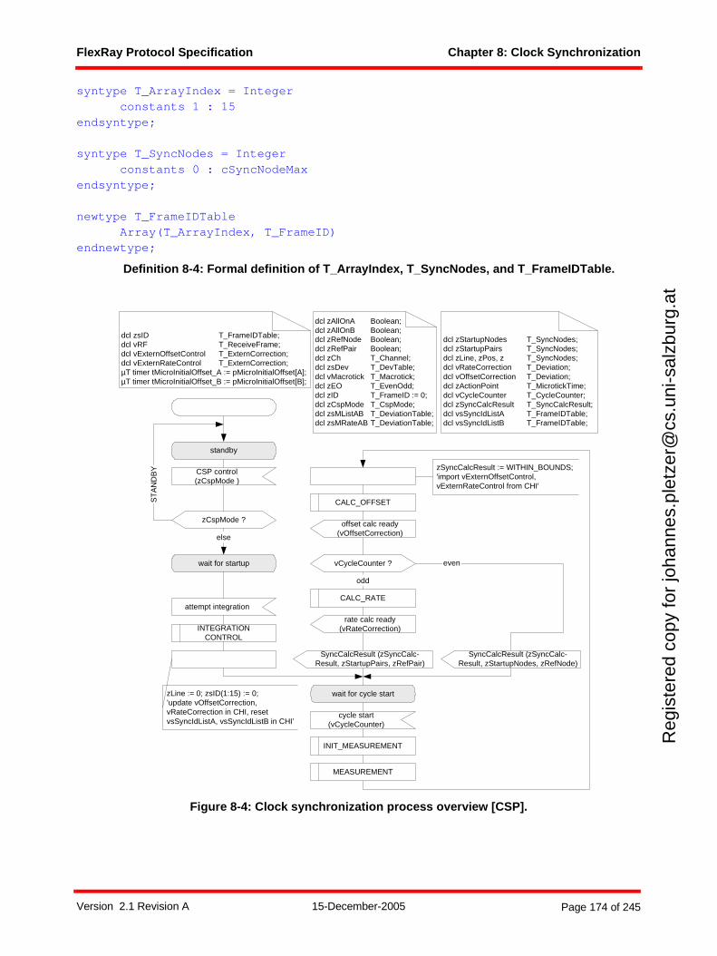
FlexRay Protocol Specification Chapter 8: Clock Synchronization
Reg
iste
red
copy
for
joha
nnes
.ple
tzer
@cs
.uni
-sal
zbur
g.at
syntype T_ArrayIndex = Integer constants 1 : 15
endsyntype;
syntype T_SyncNodes = Integer constants 0 : cSyncNodeMax
endsyntype;
newtype T_FrameIDTableArray(T_ArrayIndex, T_FrameID)
endnewtype;
Definition 8-4: Formal definition of T_ArrayIndex, T_SyncNodes, and T_FrameIDTable.
Figure 8-4: Clock synchronization process overview [CSP].
even
CALC_OFFSET
vCycleCounter ?
CALC_RATE
odd
cycle start(vCycleCounter)
wait for cycle start
dcl zStartupNodes T_SyncNodes;dcl zStartupPairs T_SyncNodes;dcl zLine, zPos, z T_SyncNodes;dcl vRateCorrection T_Deviation;dcl vOffsetCorrection T_Deviation;dcl zActionPoint T_MicrotickTime;dcl vCycleCounter T_CycleCounter;dcl zSyncCalcResult T_SyncCalcResult;dcl vsSyncIdListA T_FrameIDTable;dcl vsSyncIdListB T_FrameIDTable;
standby
CSP control(zCspMode )
zCspMode ?
ST
AN
DB
Y
else
wait for startup
attempt integration
dcl zAllOnA Boolean;dcl zAllOnB Boolean;dcl zRefNode Boolean;dcl zRefPair Boolean;dcl zCh T_Channel;dcl zsDev T_DevTable;dcl vMacrotick T_Macrotick;dcl zEO T_EvenOdd;dcl zID T_FrameID := 0;dcl zCspMode T_CspMode;dcl zsMListAB T_DeviationTable;dcl zsMRateAB T_DeviationTable;
INTEGRATIONCONTROL
SyncCalcResult (zSyncCalc-Result, zStartupNodes, zRefNode)
SyncCalcResult (zSyncCalc-Result, zStartupPairs, zRefPair)
INIT_MEASUREMENT
MEASUREMENT
dcl zsID T_FrameIDTable;dcl vRF T_ReceiveFrame;dcl vExternOffsetControl T_ExternCorrection;dcl vExternRateControl T_ExternCorrection;µT timer tMicroInitialOffset_A := pMicroInitialOffset[A];µT timer tMicroInitialOffset_B := pMicroInitialOffset[B];
zSyncCalcResult := WITHIN_BOUNDS;'import vExternOffsetControl,vExternRateControl from CHI'
zLine := 0; zsID(1:15) := 0;’update vOffsetCorrection,vRateCorrection in CHI, resetvsSyncIdListA, vsSyncIdListB in CHI’
offset calc ready(vOffsetCorrection)
rate calc ready(vRateCorrection)
Version 2.1 Revision A 15-December-2005 Page 174 of 245
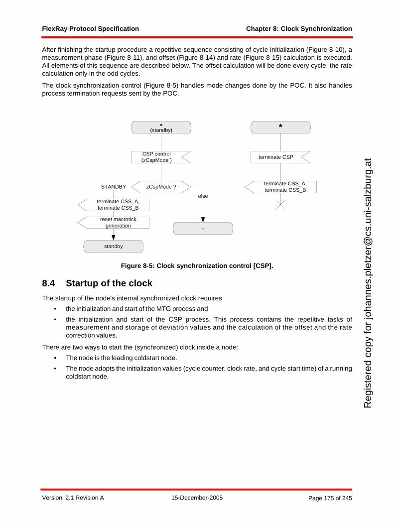
FlexRay Protocol Specification Chapter 8: Clock Synchronization
Reg
iste
red
copy
for
joha
nnes
.ple
tzer
@cs
.uni
-sal
zbur
g.at
After finishing the startup procedure a repetitive sequence consisting of cycle initialization (Figure 8-10), ameasurement phase (Figure 8-11), and offset (Figure 8-14) and rate (Figure 8-15) calculation is executed.All elements of this sequence are described below. The offset calculation will be done every cycle, the ratecalculation only in the odd cycles.
The clock synchronization control (Figure 8-5) handles mode changes done by the POC. It also handlesprocess termination requests sent by the POC.
Figure 8-5: Clock synchronization control [CSP].
8.4 Startup of the clock
The startup of the node's internal synchronized clock requires
• the initialization and start of the MTG process and
• the initialization and start of the CSP process. This process contains the repetitive tasks ofmeasurement and storage of deviation values and the calculation of the offset and the ratecorrection values.
There are two ways to start the (synchronized) clock inside a node:
• The node is the leading coldstart node.
• The node adopts the initialization values (cycle counter, clock rate, and cycle start time) of a runningcoldstart node.
*(standby)
CSP control(zCspMode )
zCspMode ?
-
standby
STANDBY
else
*
terminate CSP
terminate CSS_A,terminate CSS_B
terminate CSS_A,terminate CSS_B
reset macrotickgeneration
Version 2.1 Revision A 15-December-2005 Page 175 of 245
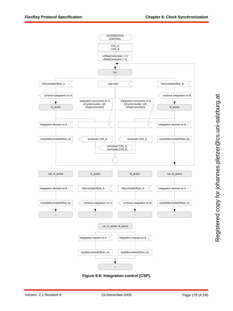
FlexRay Protocol Specification Chapter 8: Clock Synchronization
Reg
iste
red
copy
for
joha
nnes
.ple
tzer
@cs
.uni
-sal
zbur
g.at
Figure 8-6: Integration control [CSP].
run
A_active B_active
integration aborted on A
INTEGRATIONCONTROL
integration aborted on B
terminate CSS_B
tMicroInitialOffset_A tMicroInitialOffset_B
continue integration on A continue integration on B
cold start
run, A_active, B_active
integration request on A integration request on B
set(tMicroInitialOffset_A); set(tMicroInitialOffset_B);
-
reset(tMicroInitialOffset_A); reset(tMicroInitialOffset_B);
run, A_active
-
integration aborted on B
reset(tMicroInitialOffset_B);
run, B_active
-
integration aborted on A
reset(tMicroInitialOffset_A);
integration successful on A(vCycleCounter, zID,
vRateCorrection)
integration successful on B(vCycleCounter, zID,
vRateCorrection)
terminate CSS_A
CSS_A,CSS_B
terminate CSS_A,terminate CSS_B
A_active
-
tMicroInitialOffset_A
continue integration on A
B_active
-
tMicroInitialOffset_B
continue integration on B
vOffsetCorrection := 0;vRateCorrection := 0;
Version 2.1 Revision A 15-December-2005 Page 176 of 245
FlexRay Protocol Specification Chapter 8: Clock Synchronization
Reg
iste
red
copy
for
joha
nnes
.ple
tzer
@cs
.uni
-sal
zbur
g.at
The startup procedure will be entered when the CSP receives the signal attempt integration from the POC(see Figure 8-4). The control of the node's startup is described in the INTEGRATION CONTROL macrodepicted in Figure 8-6.
8.4.1 Cold start startupIf no ongoing communication on the channels is detected the POC may force the node to perform the roleof the leading coldstart node of the cluster. This causes the following actions:
• The clock synchronization startup processes on channel A and B (CSS_A, CSS_B) will be termi-nated.
• The INTEGRATION CONTROL macro will be left.
• The macrotick generation process (MTG) (Figure 8-17) leaves the MTG:wait for start state.Depending on the initialization values, macrotick and cycle start signals are generated and distrib-uted to other processes.
• The CSP waits for the cycle start.
The CSP and MTG processes continue their schedules until the POC changes the CSP mode to STANDBYor an error is detected.
8.4.2 Integration startupIf ongoing communication is detected during startup, or if the node is not allowed to perform a coldstart, thenode attempts to integrate into the timing of the cluster by adopting the rate, the cycle number, and cyclestart instant of a coldstart node. To accomplish this, the CSP process (Figure 8-6) instantiates the clocksynchronization startup processes for channel A and B (CSS_A, CSS_B).
After their instantiation, the CSS_A process (Figure 8-8) and the CSS_B process wait for a signal from thecoding/decoding unit that a potential frame start was detected. The CSS process then takes a timestampand waits for a signal indicating that a valid even startup frame was received. If no valid even startup framewas received the time stamp will be overwritten with the time stamp of the next potential frame start that isreceived.
When a valid even startup frame is received the node is able to pre-calculate the initial values for the cyclecounter and the macrotick counter. The node then waits for the corresponding odd startup frame. This frameis expected in a time window. When a potential frame start is detected in this time window the tMicroInitial-Offset timer is started in the INTEGRATION CONTROL macro. When this timer expires the MTG process(Figure 8-17) is started using the pre-calculated initial values. A second potential frame start inside the timewindow leads to a restart of the tMicroInitialOffset timer. Only one channel can start the MTG process (theinitial channel).94 Between the expiration of the timer tMicroInitialOffset and the reception of the completestartup frame, the other channel (the non-initial channel) can not start, stop, or change the MTG process,but it can receive potential frame start events and can start its own tMicroInitialOffset timer. The behavior ofthe CSS process of the non-initial channel is the same as the behavior of the CSS process of the initialchannel except that the non-initial channel is unable to start the MTG process and is unable to terminateitself and the CSS process of the other channel.
94 There is no configuration that selects the channel that starts the MTG process. The process is started by the first channel that receives a potential frame start in the expected time window after reception of a valid even startup frame on the same channel (refer to Figure 8-8).
Version 2.1 Revision A 15-December-2005 Page 177 of 245
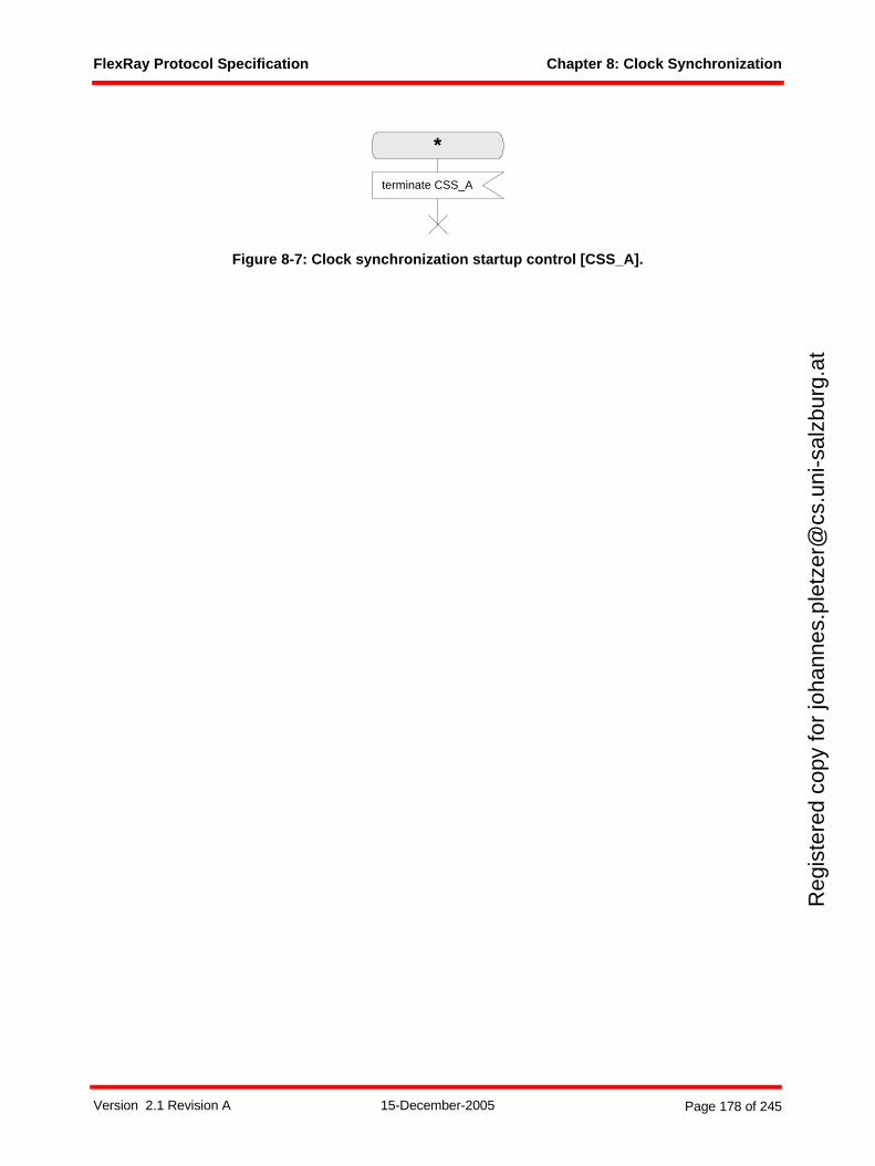
FlexRay Protocol Specification Chapter 8: Clock Synchronization
Reg
iste
red
copy
for
joha
nnes
.ple
tzer
@cs
.uni
-sal
zbur
g.at
Figure 8-7: Clock synchronization startup control [CSS_A].
*
terminate CSS_A
Version 2.1 Revision A 15-December-2005 Page 178 of 245
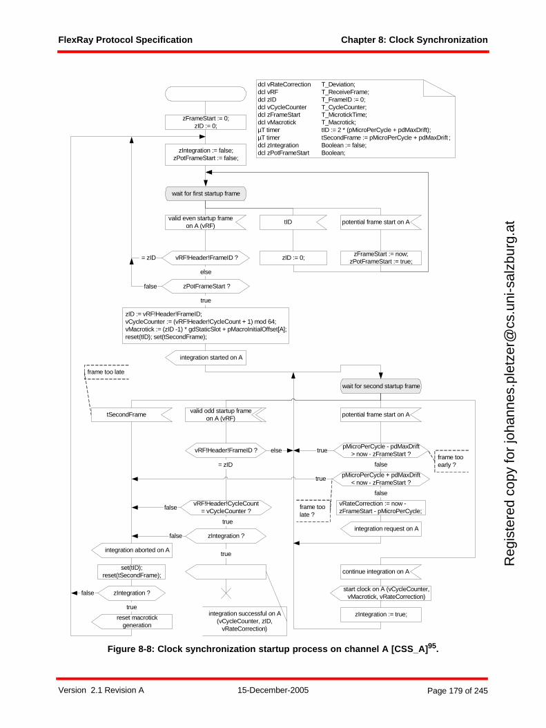
FlexRay Protocol Specification Chapter 8: Clock Synchronization
Reg
iste
red
copy
for
joha
nnes
.ple
tzer
@cs
.uni
-sal
zbur
g.at
Figure 8-8: Clock synchronization startup process on channel A [CSS_A]95.
potential frame start on A
wait for second startup frame
false
vRateCorrection := now -zFrameStart - pMicroPerCycle;
start clock on A (vCycleCounter,vMacrotick, vRateCorrection)
pMicroPerCycle - pdMaxDrift> now - zFrameStart ?true
frame tooearly ?
frame too late
vRF!Header!FrameID ?
true
= zID
else
zID := vRF!Header!FrameID;vCycleCounter := (vRF!Header!CycleCount + 1) mod 64;vMacrotick := (zID -1) * gdStaticSlot + pMacroInitialOffset[A];reset(tID); set(tSecondFrame);
valid even startup frameon A (vRF)
wait for first startup frame
zFrameStart := 0;zID := 0;
integration started on A
tSecondFrame
integration aborted on A
pMicroPerCycle + pdMaxDrift< now - zFrameStart ?
false
frame toolate ?
dcl vRateCorrection T_Deviation;dcl vRF T_ReceiveFrame;dcl zID T_FrameID := 0;dcl vCycleCounter T_CycleCounter;dcl zFrameStart T_MicrotickTime;dcl vMacrotick T_Macrotick;µT timer tID := 2 * (pMicroPerCycle + pdMaxDrift);µT timer tSecondFrame := pMicroPerCycle + pdMaxDrift ;dcl zIntegration Boolean := false;dcl zPotFrameStart Boolean;
vRF!Header!FrameID ? = zID
else
zIntegration := true;
zIntegration ?
true
false
zIntegration := false;zPotFrameStart := false;
tID
zID := 0;
set(tID);reset(tSecondFrame);
potential frame start on A
zFrameStart := now;zPotFrameStart := true;
zPotFrameStart ?
true
false
continue integration on A
integration request on A
reset macrotickgeneration
zIntegration ?
true
false
integration successful on A(vCycleCounter, zID,
vRateCorrection)
vRF!Header!CycleCount= vCycleCounter ?false
true
valid odd startup frameon A (vRF)
Version 2.1 Revision A 15-December-2005 Page 179 of 245
FlexRay Protocol Specification Chapter 8: Clock Synchronization
Reg
iste
red
copy
for
joha
nnes
.ple
tzer
@cs
.uni
-sal
zbur
g.at
The reception of the corresponding valid odd startup frame and the satisfaction of the conditions forintegration leads to the termination of the CSS process for this channel. Before termination a signal is sentindicating successful integration; this signal causes the INTEGRATION CONTROL macro of CSP toterminate the CSS process for the other channel (see Figure 8-6). This behavior of this termination isdepicted in Figure 8-7.
The timer tSecondFrame in Figure 8-8 is used to restart the clock synchronization startup process if thecorresponding odd startup frame was not received after an appropriate period of time.
The variable zID is used to prohibit attempts to integrate on a coldstart node if an integration attempt on thiscoldstart node failed in the previous cycle. The timer tID prevents this prohibition from applying for morethan one double cycle.
8.5 Time measurement
Every node shall measure and store, by channel, the time differences (in microticks) between the expectedand the observed arrival times of all sync frames received during the static segment. A data structure isintroduced in section 8.5.1. This data structure is used in the explanation of the initialization (section 8.5.2)and the measurement, storage, and deviation calculation mechanisms (section 8.5.3).
95 The priority input symbol on the state CSS_A:wait for second startup frame has been included to resolve the ambiguity that arises if the timer tSecondFrame expires at the same time a valid odd startup frame on A signal is received.
Version 2.1 Revision A 15-December-2005 Page 180 of 245
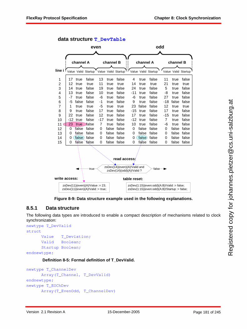
FlexRay Protocol Specification Chapter 8: Clock Synchronization
Reg
iste
red
copy
for
joha
nnes
.ple
tzer
@cs
.uni
-sal
zbur
g.at
Figure 8-9: Data structure example used in the following explanations.
8.5.1 Data structureThe following data types are introduced to enable a compact description of mechanisms related to clocksynchronization:newtype T_DevValidstruct
Value T_Deviation;Valid Boolean;Startup Boolean;
endnewtype;
Definition 8-5: Formal definition of T_DevValid.
newtype T_ChannelDevArray(T_Channel, T_DevValid)
endnewtype;newtype T_EOChDev
Array(T_EvenOdd, T_ChannelDev)
channel A channel B channel A channel B
even odd
line i
123456789
101112131415
zsDev(11)(even)(A)!Value := 23;zsDev(11)(even)(A)!Valid := true;
data structure T_DevTable
zsDev(14)(even)(A)!Valid andzsDev(14)(odd)(A)!Valid ?
read access:
write access: table reset:
zsDev(1:15)(even:odd)(A:B)!Valid := false;zsDev(1:15)(even:odd)(A:B)!Startup := false;
falsetrue
Value Valid Startup Value Valid Startup Value Valid Startup Value Valid Startup
17121413-7-519
22-12230000
truetruetruetruetruefalsetruetruetruetruetruefalsefalsefalsefalse
falsetruefalsefalsefalsefalsetruefalsefalsefalsefalsefalsefalsefalsefalse
13111910-6-1-51712-1770000
truetruetruetruetruetruetruetruetruetruetruefalsefalsefalsefalse
falsetruefalsefalsefalsefalsetruefalsefalsefalsefalsefalsefalsefalsefalse
41424-11-69
23-1517-12100000
truetruetruetruetruetruefalsetruetruetruetruefalsefalsefalsefalse
falsetruefalsefalsefalsefalsefalsefalsefalsefalsefalsefalsefalsefalsefalse
11215-827-181217-157-60000
truetruetruetruetruefalsetruetruetruetruetruefalsefalsefalsefalse
falsetruefalsefalsefalsefalsetruefalsefalsefalsefalsefalsefalsefalsefalse
Version 2.1 Revision A 15-December-2005 Page 181 of 245
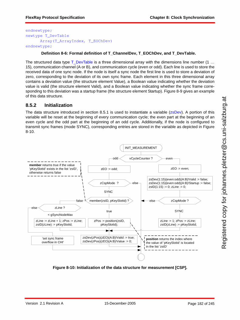
FlexRay Protocol Specification Chapter 8: Clock Synchronization
Reg
iste
red
copy
for
joha
nnes
.ple
tzer
@cs
.uni
-sal
zbur
g.at
endnewtype;newtype T_DevTable
Array(T_ArrayIndex, T_EOChDev)endnewtype;
Definition 8-6: Formal definition of T_ChannelDev, T_EOChDev, and T_DevTable.
The structured data type T_DevTable is a three dimensional array with the dimensions line number (1 …15), communication channel (A or B), and communication cycle (even or odd). Each line is used to store thereceived data of one sync node. If the node is itself a sync node the first line is used to store a deviation ofzero, corresponding to the deviation of its own sync frame. Each element in this three dimensional arraycontains a deviation value (the structure element Value), a Boolean value indicating whether the deviationvalue is valid (the structure element Valid), and a Boolean value indicating whether the sync frame corre-sponding to this deviation was a startup frame (the structure element Startup). Figure 8-9 gives an exampleof this data structure.
8.5.2 InitializationThe data structure introduced in section 8.5.1 is used to instantiate a variable (zsDev). A portion of thisvariable will be reset at the beginning of every communication cycle; the even part at the beginning of aneven cycle and the odd part at the beginning of an odd cycle. Additionally, if the node is configured totransmit sync frames (mode SYNC), corresponding entries are stored in the variable as depicted in Figure8-10.
Figure 8-10: Initialization of the data structure for measurement [CSP].
INIT_MEASUREMENT
vCycleCounter ?
zEO := even;zEO := odd;
evenodd
zsDev(zPos)(zEO)(A:B)!Valid := true;zsDev(zPos)(zEO)(A:B)!Value := 0;
zCspMode ?
SYNC
else
zLine := zLine + 1; zPos := zLine;zsID(zLine) := pKeySlotId;
zsDev(1:15)(even:odd)(A:B)!Valid := false;zsDev(1:15)(even:odd)(A:B)!Startup := false;zsID(1:15) := 0; zLine := 0;
zCspMode ?
SYNC
zLine := 1; zPos := zLine;zsID(zLine) := pKeySlotId;
member(zsID, pKeySlotId) ?
true
zPos := position(zsID,pKeySlotId);
else
false
zLine ?
< gSyncNodeMax
'set sync frameoverflow in CHI'
else
member returns true if the value’pKeySlotId’ exists in the list ’zsID’,otherwise returns false
position returns the index wherethe value of ’pKeySlotId’ is locatedin the list ’zsID’
Version 2.1 Revision A 15-December-2005 Page 182 of 245
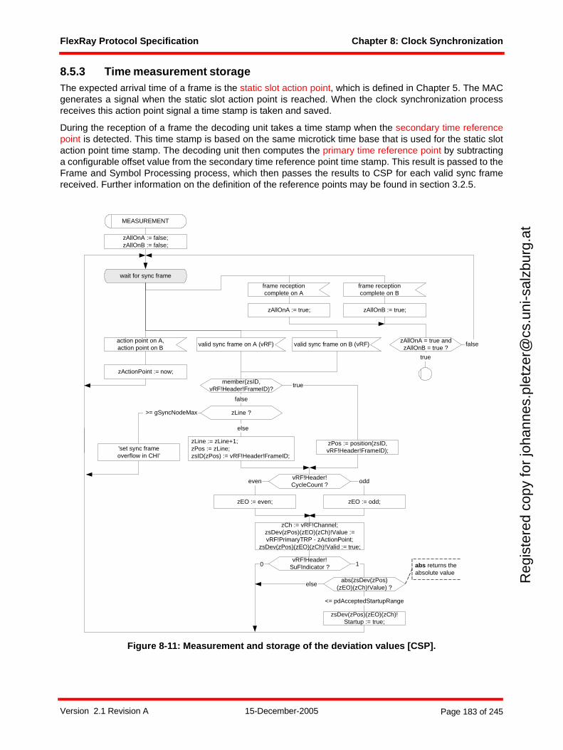
FlexRay Protocol Specification Chapter 8: Clock Synchronization
Reg
iste
red
copy
for
joha
nnes
.ple
tzer
@cs
.uni
-sal
zbur
g.at
8.5.3 Time measurement storageThe expected arrival time of a frame is the static slot action point, which is defined in Chapter 5. The MACgenerates a signal when the static slot action point is reached. When the clock synchronization processreceives this action point signal a time stamp is taken and saved.
During the reception of a frame the decoding unit takes a time stamp when the secondary time referencepoint is detected. This time stamp is based on the same microtick time base that is used for the static slotaction point time stamp. The decoding unit then computes the primary time reference point by subtractinga configurable offset value from the secondary time reference point time stamp. This result is passed to theFrame and Symbol Processing process, which then passes the results to CSP for each valid sync framereceived. Further information on the definition of the reference points may be found in section 3.2.5.
Figure 8-11: Measurement and storage of the deviation values [CSP].
wait for sync frame
valid sync frame on A (vRF)
member(zsID,vRF!Header!FrameID)?
zPos := position(zsID,vRF!Header!FrameID);
true
false
else
zLine ? >= gSyncNodeMax
action point on A,action point on B
zActionPoint := now;
MEASUREMENT
true
vRF!Header!CycleCount ?
zEO := even; zEO := odd;
even odd
zLine := zLine+1;zPos := zLine;zsID(zPos) := vRF!Header!FrameID;
vRF!Header!SuFIndicator ?
zCh := vRF!Channel;zsDev(zPos)(zEO)(zCh)!Value :=vRF!PrimaryTRP - zActionPoint;
zsDev(zPos)(zEO)(zCh)!Valid := true;
0
abs(zsDev(zPos)(zEO)(zCh)!Value) ?
1
else
zsDev(zPos)(zEO)(zCh)!Startup := true;
<= pdAcceptedStartupRange
valid sync frame on B (vRF)
'set sync frameoverflow in CHI'
abs returns theabsolute value
frame receptioncomplete on A
frame receptioncomplete on B
zAllOnA := true; zAllOnB := true;
zAllOnA = true andzAllOnB = true ?
false
zAllOnA := false;zAllOnB := false;
Version 2.1 Revision A 15-December-2005 Page 183 of 245
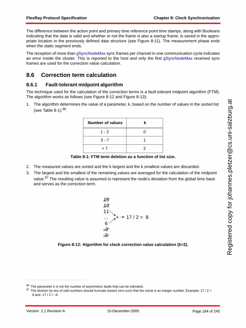
FlexRay Protocol Specification Chapter 8: Clock Synchronization
Reg
iste
red
copy
for
joha
nnes
.ple
tzer
@cs
.uni
-sal
zbur
g.at
The difference between the action point and primary time reference point time stamps, along with Booleansindicating that the data is valid and whether or not the frame is also a startup frame, is saved in the appro-priate location in the previously defined data structure (see Figure 8-11). The measurement phase endswhen the static segment ends.
The reception of more than gSyncNodeMax sync frames per channel in one communication cycle indicatesan error inside the cluster. This is reported to the host and only the first gSyncNodeMax received syncframes are used for the correction value calculation.
8.6 Correction term calculation
8.6.1 Fault-tolerant midpoint algorithmThe technique used for the calculation of the correction terms is a fault-tolerant midpoint algorithm (FTM).The algorithm works as follows (see Figure 8-12 and Figure 8-13):
1. The algorithm determines the value of a parameter, k, based on the number of values in the sorted list
(see Table 8-1).96
2. The measured values are sorted and the k largest and the k smallest values are discarded.
3. The largest and the smallest of the remaining values are averaged for the calculation of the midpoint
value.97 The resulting value is assumed to represent the node's deviation from the global time base and serves as the correction term.
Figure 8-12: Algorithm for clock correction value calculation (k=2).
Number of values k
1 - 2 0
3 - 7 1
> 7 2
Table 8-1: FTM term deletion as a function of list size.
96 The parameter k is not the number of asymmetric faults that can be tolerated.97 The division by two of odd numbers should truncate toward zero such that the result is an integer number. Example: 17 / 2 =
8 and -17 / 2 = -8.
151311… 6-3-5
17 / 2 = 8+
Version 2.1 Revision A 15-December-2005 Page 184 of 245
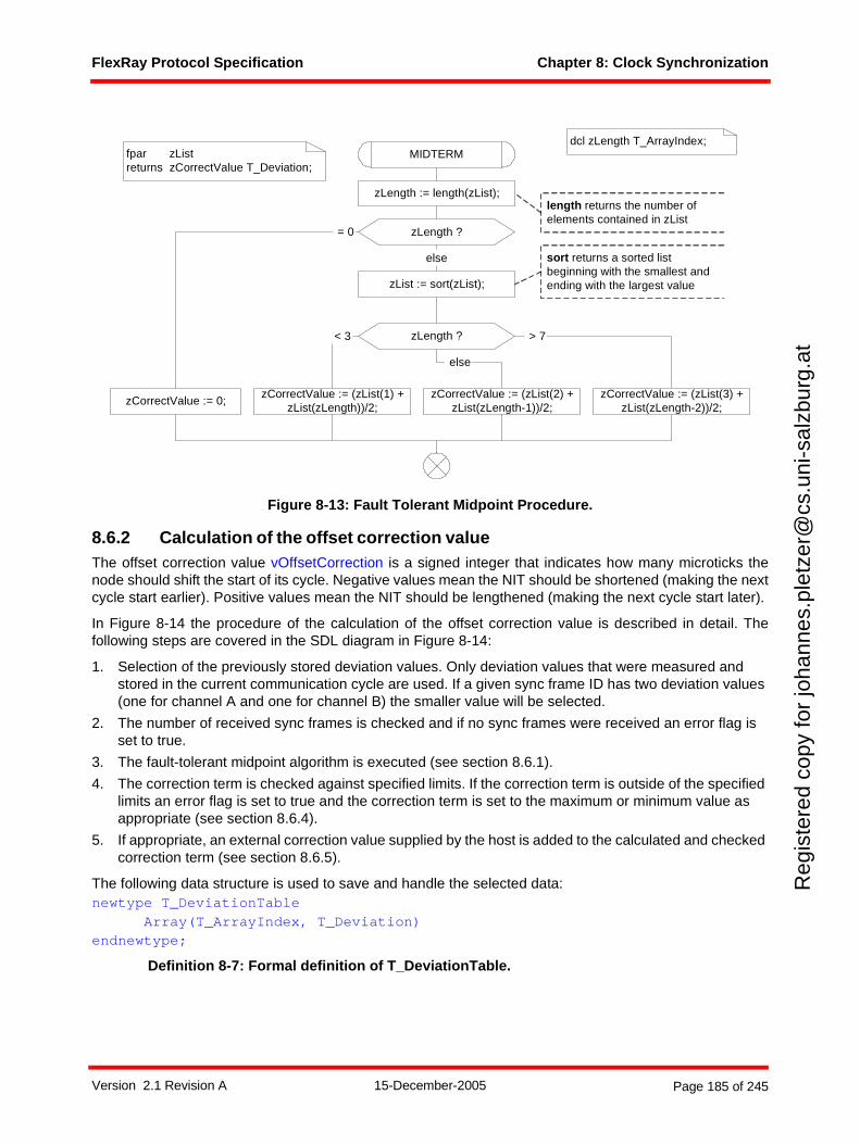
FlexRay Protocol Specification Chapter 8: Clock Synchronization
Reg
iste
red
copy
for
joha
nnes
.ple
tzer
@cs
.uni
-sal
zbur
g.at
Figure 8-13: Fault Tolerant Midpoint Procedure.
8.6.2 Calculation of the offset correction valueThe offset correction value vOffsetCorrection is a signed integer that indicates how many microticks thenode should shift the start of its cycle. Negative values mean the NIT should be shortened (making the nextcycle start earlier). Positive values mean the NIT should be lengthened (making the next cycle start later).
In Figure 8-14 the procedure of the calculation of the offset correction value is described in detail. Thefollowing steps are covered in the SDL diagram in Figure 8-14:
1. Selection of the previously stored deviation values. Only deviation values that were measured and stored in the current communication cycle are used. If a given sync frame ID has two deviation values (one for channel A and one for channel B) the smaller value will be selected.
2. The number of received sync frames is checked and if no sync frames were received an error flag is set to true.
3. The fault-tolerant midpoint algorithm is executed (see section 8.6.1).
4. The correction term is checked against specified limits. If the correction term is outside of the specified limits an error flag is set to true and the correction term is set to the maximum or minimum value as appropriate (see section 8.6.4).
5. If appropriate, an external correction value supplied by the host is added to the calculated and checked correction term (see section 8.6.5).
The following data structure is used to save and handle the selected data:newtype T_DeviationTable
Array(T_ArrayIndex, T_Deviation)endnewtype;
Definition 8-7: Formal definition of T_DeviationTable.
zLength := length(zList);
zLength ?
zCorrectValue := 0;
= 0
else
zList := sort(zList);
MIDTERM
zLength ? > 7
zCorrectValue := (zList(1) +zList(zLength))/2;
< 3
else
zCorrectValue := (zList(2) +zList(zLength-1))/2;
zCorrectValue := (zList(3) +zList(zLength-2))/2;
fpar zListreturns zCorrectValue T_Deviation;
dcl zLength T_ArrayIndex;
length returns the number ofelements contained in zList
sort returns a sorted listbeginning with the smallest andending with the largest value
Version 2.1 Revision A 15-December-2005 Page 185 of 245
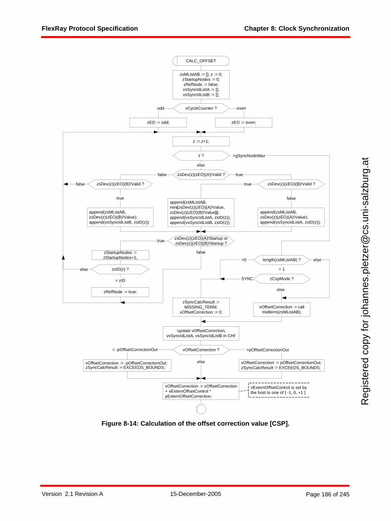
FlexRay Protocol Specification Chapter 8: Clock Synchronization
Reg
iste
red
copy
for
joha
nnes
.ple
tzer
@cs
.uni
-sal
zbur
g.at
Figure 8-14: Calculation of the offset correction value [CSP].
else
>gSyncNodeMax
length(zsMListAB) ? =0
= 1
else
z ?
else
truefalse
true
falsetrue
false
z := z+1;
zsDev(z)(zEO)(A)!Valid ?
zsDev(z)(zEO)(B)!Valid ?
zEO := odd;
append(zsMListAB,zsDev(z)(zEO)(B)!Value);append(vsSyncIdListB, zsID(z));
append(zsMListAB,min(zsDev(z)(zEO)(A)!Value,zsDev(z)(zEO)(B)!Value));append(vsSyncIdListA, zsID(z));append(vsSyncIdListB, zsID(z));
append(zsMListAB,zsDev(z)(zEO)(A)!Value);append(vsSyncIdListA, zsID(z));
zsDev(z)(zEO)(B)!Valid ?
zCspMode ?
CALC_OFFSET
>pOffsetCorrectionOut
vOffsetCorrection := vOffsetCorrection+ vExternOffsetControl *pExternOffsetCorrection;
vOffsetCorrection ?
vOffsetCorrection := pOffsetCorrectionOut;zSyncCalcResult := EXCEEDS_BOUNDS;
vOffsetCorrection := -pOffsetCorrectionOut;zSyncCalcResult := EXCEEDS_BOUNDS;
< -pOffsetCorrectionOut
else
vCycleCounter ?
zEO := even;
odd even
zsMListAB := []; z := 0;zStartupNodes := 0;zRefNode := false;vsSyncIdListA := [];vsSyncIdListB := [];
zStartupNodes :=zStartupNodes+1;
zsDev(z)(zEO)(A)!Startup orzsDev(z)(zEO)(B)!Startup ?
true
false
zsID(z) ?
zRefNode := true;
= zID SYNC
else
vOffsetCorrection := callmidterm(zsMListAB);
vExternOffsetControl is set bythe host to one of { -1, 0, +1 }
zSyncCalcResult :=MISSING_TERM;
vOffsetCorrection := 0;
’update vOffsetCorrection,vsSyncIdListA, vsSyncIdListB in CHI’
Version 2.1 Revision A 15-December-2005 Page 186 of 245

FlexRay Protocol Specification Chapter 8: Clock Synchronization
Reg
iste
red
copy
for
joha
nnes
.ple
tzer
@cs
.uni
-sal
zbur
g.at
The SDL abstraction of execution in zero time could lead the reader to the conclusion that the calculationof the offset correction value needs to complete in zero time. This is of course unachievable. It is anticipatedthat real implementations may take substantial time to calculate the correction, and that implementationsmay begin the calculation earlier than is shown in Figure 8-4 (i.e., may begin the calculation during themeasurement process). Therefore the following restriction on the time required for offset correction calcu-lation is introduced:
The offset correction calculation must be completed no later than cdMaxOffsetCalculation after the end of the static segment or 1 MT after the start of the NIT, whichever occurs later.
8.6.3 Calculation of the rate correction valueThe goal of the rate correction is to bring the rates of all nodes inside the cluster close together. The ratecorrection value is determined by comparing the corresponding measured time differences from twosuccessive cycles. A detailed description is given by the SDL diagram depicted in Figure 8-15.
Version 2.1 Revision A 15-December-2005 Page 187 of 245
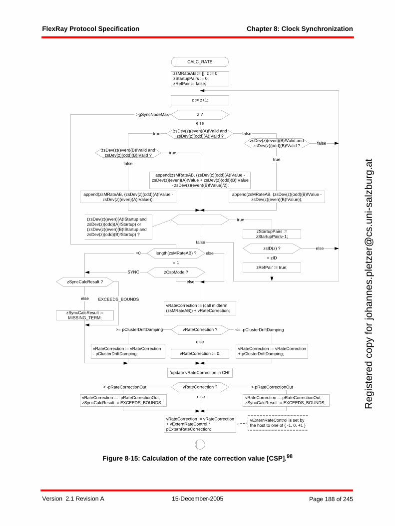
FlexRay Protocol Specification Chapter 8: Clock Synchronization
Reg
iste
red
copy
for
joha
nnes
.ple
tzer
@cs
.uni
-sal
zbur
g.at
Figure 8-15: Calculation of the rate correction value [CSP].98
false
>gSyncNodeMax
else
true false
true
falsetrue
false
>= pClusterDriftDamping <= -pClusterDriftDamping
else
z := z+1;
CALC_RATE
z ?
zsMRateAB := []; z := 0;zStartupPairs := 0;zRefPair := false;
zsDev(z)(even)(A)!Valid andzsDev(z)(odd)(A)!Valid ?
zsDev(z)(even)(B)!Valid andzsDev(z)(odd)(B)!Valid ?
zsDev(z)(even)(B)!Valid andzsDev(z)(odd)(B)!Valid ?
append(zsMRateAB, (zsDev(z)(odd)(A)!Value -zsDev(z)(even)(A)!Value));
append(zsMRateAB, (zsDev(z)(odd)(B)!Value -zsDev(z)(even)(B)!Value));
append(zsMRateAB, (zsDev(z)(odd)(A)!Value -zsDev(z)(even)(A)!Value + zsDev(z)(odd)(B)!Value
- zsDev(z)(even)(B)!Value)/2);
vRateCorrection := (call midterm(zsMRateAB)) + vRateCorrection;
vRateCorrection ?
vRateCorrection := 0;vRateCorrection := vRateCorrection+ pClusterDriftDamping;
vRateCorrection := vRateCorrection- pClusterDriftDamping;
> pRateCorrectionOut
else
vRateCorrection := vRateCorrection+ vExternRateControl *pExternRateCorrection;
vRateCorrection ? < -pRateCorrectionOut
vRateCorrection := -pRateCorrectionOut;zSyncCalcResult := EXCEEDS_BOUNDS;
vRateCorrection := pRateCorrectionOut;zSyncCalcResult := EXCEEDS_BOUNDS;
zStartupPairs :=zStartupPairs+1;
true
zsID(z) ?
zRefPair := true;
= zID
elselength(zsMRateAB) ? =0
= 1
else
zCspMode ?SYNC
else
vExternRateControl is set bythe host to one of { -1, 0, +1 }
zSyncCalcResult :=MISSING_TERM;
zSyncCalcResult ?
EXCEEDS_BOUNDSelse
’update vRateCorrection in CHI’
(zsDev(z)(even)(A)!Startup andzsDev(z)(odd)(A)!Startup) or(zsDev(z)(even)(B)!Startup andzsDev(z)(odd)(B)!Startup) ?
Version 2.1 Revision A 15-December-2005 Page 188 of 245

FlexRay Protocol Specification Chapter 8: Clock Synchronization
Reg
iste
red
copy
for
joha
nnes
.ple
tzer
@cs
.uni
-sal
zbur
g.at
The rate correction value vRateCorrection is a signed integer indicating by how many microticks the node'scycle length should be changed. Negative values mean the cycle should be shortened; positive valuesmean the cycle should be lengthened.
The following steps are depicted in the SDL diagram in Figure 8-15:
1. Pairs of previously stored deviation values are selected and the difference between the values within a pair is calculated. Pairs are selected that represent sync frames received on the same channel, in the same slot, on consecutive cycles. If there are two pairs for a given sync frame ID (one pair for channel A and another pair for channel B) the average of the differences is used.
2. The number of received sync frame pairs is checked and if no sync frame pairs were received an error flag is set to true.
3. The fault-tolerant midpoint algorithm is executed (see section 8.6.1).
4. A damping value pClusterDriftDamping for the rate correction term is applied.
5. The correction term is checked against specified limits. If the correction term exceeds the specified limits an error flag is set to true and the correction term is set to the maximum or minimum value as appropriate (see section 8.6.4).
6. If appropriate, an external correction value supplied by the host is added to the calculated correction term (see section 8.6.5).
The pClusterDriftDamping parameter should be configured in such a way that the damping value in allnodes has approximately the same duration.99
The SDL abstraction of execution in zero time introduces similar problems for the rate correction calculationas are described in section 8.6.2 for the offset correction calculation. Therefore the following restriction onthe time required for rate correction calculation is introduced:
The rate correction calculation must be completed no later than cdMaxRateCalculation after the end of the static segment or 2 MT after the start of the NIT, whichever occurs later.
8.6.4 Value limitationsBefore applying the calculated correction values, they shall be checked against pre-configured limits (seeFigure 8-14 and Figure 8-15)
If correction values are inside the limits, the node is considered fully synchronized.
If either of the correction values is outside of the limits, the node is out of synchronization. This correspondsto an error condition. Information on the handling of this situation is specified in Chapter 2.
The correction values are inside the limits if:
- pRateCorrectionOut <= vRateCorrection <= pRateCorrectionOut
- pOffsetCorrectionOut <= vOffsetCorrection <= pOffsetCorrectionOut
If both correction values are inside the limits the correction will be performed; if either value exceeds its pre-configured limit, an error is reported and the node enters the POC:normal passive or the POC:halt statedepending on the configured behavior (see Chapter 2). If a value is outside its pre-configured limit it isreduced or increased to its limit. If operation continues, the correction is performed with this modified value.
98 The division by two of odd numbers should truncate toward zero such that the result is an integer number. Example: 17 / 2 = 8 and -17 / 2 = -8.
99 A node-specific configuration value is used to allow clusters that have different microtick durations in different nodes.
Version 2.1 Revision A 15-December-2005 Page 189 of 245
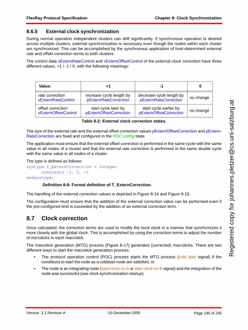
FlexRay Protocol Specification Chapter 8: Clock Synchronization
Reg
iste
red
copy
for
joha
nnes
.ple
tzer
@cs
.uni
-sal
zbur
g.at
8.6.5 External clock synchronizationDuring normal operation independent clusters can drift significantly. If synchronous operation is desiredacross multiple clusters, external synchronization is necessary even though the nodes within each clusterare synchronized. This can be accomplished by the synchronous application of host-determined externalrate and offset correction terms to both clusters.
The control data vExternRateControl and vExternOffsetControl of the external clock correction have threedifferent values, +1 / -1 / 0, with the following meanings:
The size of the external rate and the external offset correction values pExternOffsetCorrection and pExtern-RateCorrection are fixed and configured in the POC:config state.
The application must ensure that the external offset correction is performed in the same cycle with the samevalue in all nodes of a cluster and that the external rate correction is performed in the same double cyclewith the same value in all nodes of a cluster.
The type is defined as follows:syntype T_ExternCorrection = Integer
constants -1, 0, +1endsyntype;
Definition 8-8: Formal definition of T_ExternCorrection.
The handling of the external correction values is depicted in Figure 8-14 and Figure 8-15.
The configuration must ensure that the addition of the external correction value can be performed even ifthe pre-configured limit is exceeded by the addition of an external correction term.
8.7 Clock correction
Once calculated, the correction terms are used to modify the local clock in a manner that synchronizes itmore closely with the global clock. This is accomplished by using the correction terms to adjust the numberof microticks in each macrotick.
The macrotick generation (MTG) process (Figure 8-17) generates (corrected) macroticks. There are twodifferent ways to start the macrotick generation process:
• The protocol operation control (POC) process starts the MTG process (cold start signal) if theconditions to start the node as a coldstart node are satisfied, or
• The node is an integrating node (start clock on A or start clock on B signal) and the integration of thenode was successful (see clock synchronization startup).
Value: +1 -1 0
rate correctionvExternRateControl
increase cycle length by pExternRateCorrection
decrease cycle length by pExternRateCorrection no change
offset correctionvExternOffsetControl
start cycle later by pExternOffsetCorrection
start cycle earlier by pExternOffsetCorrection no change
Table 8-2: External clock correction states.
Version 2.1 Revision A 15-December-2005 Page 190 of 245
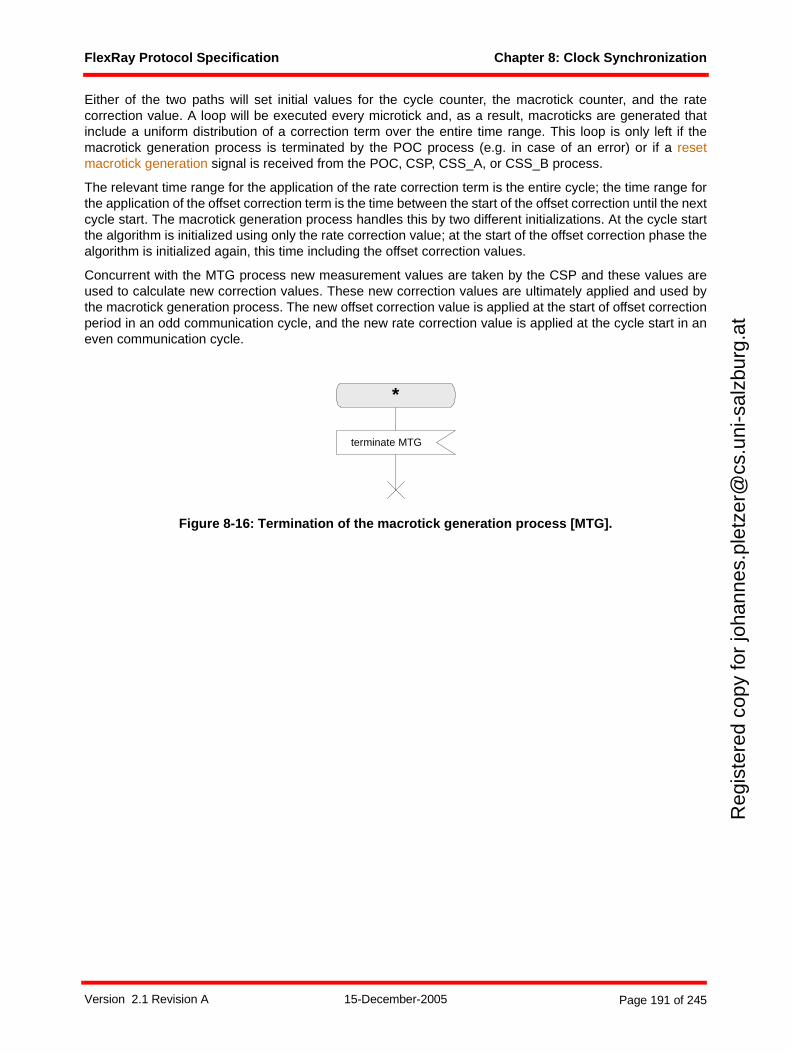
FlexRay Protocol Specification Chapter 8: Clock Synchronization
Reg
iste
red
copy
for
joha
nnes
.ple
tzer
@cs
.uni
-sal
zbur
g.at
Either of the two paths will set initial values for the cycle counter, the macrotick counter, and the ratecorrection value. A loop will be executed every microtick and, as a result, macroticks are generated thatinclude a uniform distribution of a correction term over the entire time range. This loop is only left if themacrotick generation process is terminated by the POC process (e.g. in case of an error) or if a resetmacrotick generation signal is received from the POC, CSP, CSS_A, or CSS_B process.
The relevant time range for the application of the rate correction term is the entire cycle; the time range forthe application of the offset correction term is the time between the start of the offset correction until the nextcycle start. The macrotick generation process handles this by two different initializations. At the cycle startthe algorithm is initialized using only the rate correction value; at the start of the offset correction phase thealgorithm is initialized again, this time including the offset correction values.
Concurrent with the MTG process new measurement values are taken by the CSP and these values areused to calculate new correction values. These new correction values are ultimately applied and used bythe macrotick generation process. The new offset correction value is applied at the start of offset correctionperiod in an odd communication cycle, and the new rate correction value is applied at the cycle start in aneven communication cycle.
Figure 8-16: Termination of the macrotick generation process [MTG].
*
terminate MTG
Version 2.1 Revision A 15-December-2005 Page 191 of 245
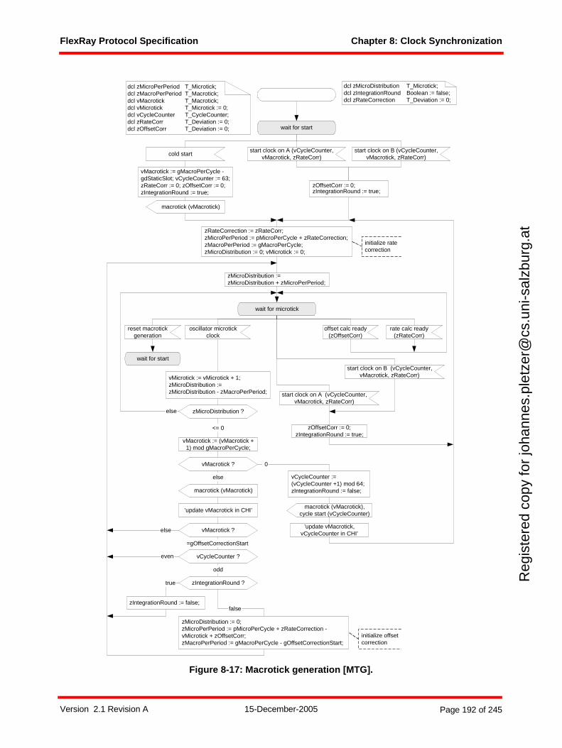
FlexRay Protocol Specification Chapter 8: Clock Synchronization
Reg
iste
red
copy
for
joha
nnes
.ple
tzer
@cs
.uni
-sal
zbur
g.at
Figure 8-17: Macrotick generation [MTG].
zMicroDistribution ?else
<= 0
vMacrotick := (vMacrotick +1) mod gMacroPerCycle;
vMacrotick ?
=gOffsetCorrectionStart
even
odd
zMicroDistribution := 0;zMicroPerPeriod := pMicroPerCycle + zRateCorrection -vMicrotick + zOffsetCorr;zMacroPerPeriod := gMacroPerCycle - gOffsetCorrectionStart;
zRateCorrection := zRateCorr;zMicroPerPeriod := pMicroPerCycle + zRateCorrection;zMacroPerPeriod := gMacroPerCycle;zMicroDistribution := 0; vMicrotick := 0;
vMacrotick ?
vCycleCounter :=(vCycleCounter +1) mod 64;zIntegrationRound := false;
0
else
oscillator microtickclock
vMicrotick := vMicrotick + 1;zMicroDistribution :=zMicroDistribution - zMacroPerPeriod;
vCycleCounter ?
macrotick (vMacrotick)
wait for microtick
macrotick (vMacrotick),cycle start (vCycleCounter)
zMicroDistribution :=zMicroDistribution + zMicroPerPeriod;
else
initialize offsetcorrection
initialize ratecorrection
wait for start
start clock on A (vCycleCounter,vMacrotick, zRateCorr)
cold start
vMacrotick := gMacroPerCycle -gdStaticSlot; vCycleCounter := 63;zRateCorr := 0; zOffsetCorr := 0;zIntegrationRound := true;
reset macrotickgeneration
offset calc ready(zOffsetCorr)
dcl zMicroPerPeriod T_Microtick;dcl zMacroPerPeriod T_Macrotick;dcl vMacrotick T_Macrotick;dcl vMicrotick T_Microtick := 0;dcl vCycleCounter T_CycleCounter;dcl zRateCorr T_Deviation := 0;dcl zOffsetCorr T_Deviation := 0;
macrotick (vMacrotick)
start clock on A (vCycleCounter,vMacrotick, zRateCorr)
zOffsetCorr := 0;zIntegrationRound := true;
zOffsetCorr := 0;zIntegrationRound := true;
dcl zMicroDistribution T_Microtick;dcl zIntegrationRound Boolean := false;dcl zRateCorrection T_Deviation := 0;
zIntegrationRound ?true
falsezIntegrationRound := false;
start clock on B (vCycleCounter,vMacrotick, zRateCorr)
start clock on B (vCycleCounter,vMacrotick, zRateCorr)
’update vMacrotick,vCycleCounter in CHI’
’update vMacrotick in CHI’
wait for start
rate calc ready(zRateCorr)
Version 2.1 Revision A 15-December-2005 Page 192 of 245

FlexRay Protocol Specification Chapter 8: Clock Synchronization
Reg
iste
red
copy
for
joha
nnes
.ple
tzer
@cs
.uni
-sal
zbur
g.at
8.8 Sync frame configuration rules
FlexRay supports a distributed clock synchronization that can be configured in many different ways. Table8-3 illustrates a number of rules constraining the possible configurations.
A number of nodes must be configured as sync nodes depending on the following rules:
• At least three nodes shall be configured to be sync nodes.
• At most cSyncNodeMax nodes shall be configured to be sync nodes.
• Only nodes with pChannels = gChannels may be sync nodes (i.e., sync nodes must be connectedto all configured channels).
• Sync nodes that support two channels shall send two sync frames, one on each channel, in a singleslot of the static segment.100 Sync nodes that only support a single channel shall send one syncframe in one slot of the static segment. The sync frames shall be sent in the same slot in each cycle.
• Non sync nodes must not transmit frames with the sync frame indicator set to one.
Element Limit, range
Number of sync nodes [3a … cSyncNodeMax]
a Even if only two sync nodes are operating in POC:nor-mal active state communication within the cluster will still take place in accordance with the communication cycle. The communication in such a cluster will, however, stop upon failure of any one of the two sync nodes.
Number of static slots >= number of sync nodes
Number of sync frames = number of sync nodes
Table 8-3: Configuration rules for the distributed clock synchronization.
100 The frames sent on the two channels in the sync slot do not need to be identical (i.e., they may have differing payloads), but they must both be sync frames.
Version 2.1 Revision A 15-December-2005 Page 193 of 245
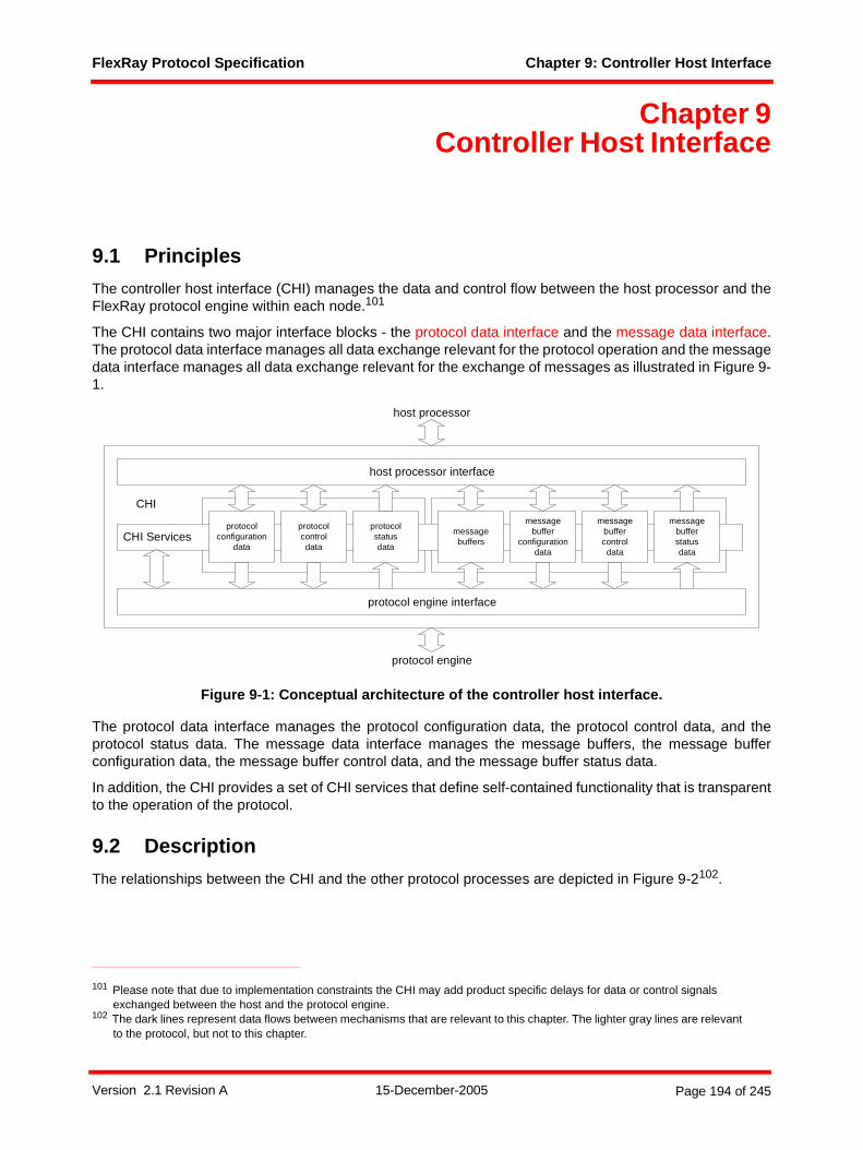
FlexRay Protocol Specification Chapter 9: Controller Host Interface
Reg
iste
red
copy
for
joha
nnes
.ple
tzer
@cs
.uni
-sal
zbur
g.at
Chapter 9Controller Host Interface
9.1 Principles
The controller host interface (CHI) manages the data and control flow between the host processor and theFlexRay protocol engine within each node.101
The CHI contains two major interface blocks - the protocol data interface and the message data interface.The protocol data interface manages all data exchange relevant for the protocol operation and the messagedata interface manages all data exchange relevant for the exchange of messages as illustrated in Figure 9-1.
Figure 9-1: Conceptual architecture of the controller host interface.
The protocol data interface manages the protocol configuration data, the protocol control data, and theprotocol status data. The message data interface manages the message buffers, the message bufferconfiguration data, the message buffer control data, and the message buffer status data.
In addition, the CHI provides a set of CHI services that define self-contained functionality that is transparentto the operation of the protocol.
9.2 Description
The relationships between the CHI and the other protocol processes are depicted in Figure 9-2102.
101 Please note that due to implementation constraints the CHI may add product specific delays for data or control signals exchanged between the host and the protocol engine.
102 The dark lines represent data flows between mechanisms that are relevant to this chapter. The lighter gray lines are relevant to the protocol, but not to this chapter.
host processor
protocol engine
CHI Servicesprotocol
configurationdata
host processor interface
protocol engine interface
CHI
protocolcontroldata
protocolstatusdata
messagebuffer
configurationdata
messagebuffers
messagebuffercontroldata
messagebufferstatusdata
Version 2.1 Revision A 15-December-2005 Page 194 of 245
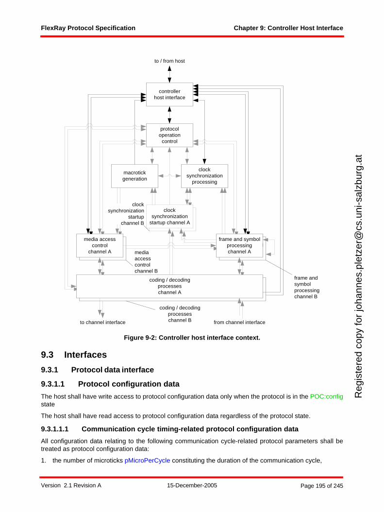
FlexRay Protocol Specification Chapter 9: Controller Host Interface
Reg
iste
red
copy
for
joha
nnes
.ple
tzer
@cs
.uni
-sal
zbur
g.at
Figure 9-2: Controller host interface context.
9.3 Interfaces
9.3.1 Protocol data interface
9.3.1.1 Protocol configuration data
The host shall have write access to protocol configuration data only when the protocol is in the POC:configstate
The host shall have read access to protocol configuration data regardless of the protocol state.
9.3.1.1.1 Communication cycle timing-related protocol configuration data
All configuration data relating to the following communication cycle-related protocol parameters shall betreated as protocol configuration data:
1. the number of microticks pMicroPerCycle constituting the duration of the communication cycle,
frame and symbolprocessing
media accesscontrol
clocksynchronization
startup
macrotickgeneration
clocksynchronization
processing
protocoloperation
control
controllerhost interface
coding / decodingprocesseschannel A
frame and symbolprocessingchannel A
media accesscontrol
channel A
clocksynchronization
startup channel A
to channel interface from channel interface
to / from host
mediaaccesscontrolchannel B
coding / decodingprocesseschannel B
frame andsymbolprocessingchannel B
clocksynchronization
startupchannel B
Version 2.1 Revision A 15-December-2005 Page 195 of 245

FlexRay Protocol Specification Chapter 9: Controller Host Interface
Reg
iste
red
copy
for
joha
nnes
.ple
tzer
@cs
.uni
-sal
zbur
g.at
2. the number of macroticks gMacroPerCycle within a communication cycle,
3. the number of static slots gNumberOfStaticSlots in the static segment,
4. the number of macroticks gdStaticSlot constituting the duration of a static slot within the static seg-ment,
5. the number of macroticks gdActionPointOffset constituting the offset of the action point within static slots and symbol window,
6. the number of macroticks gdMinislot constituting the duration of a minislot,
7. the number of minislots gNumberOfMinislots within the dynamic segment,
8. the number of macroticks gdMinislotActionPointOffset constituting the offset of the action point within a minislot of the dynamic slot,
9. the number of minislots gdDynamicSlotIdlePhase constituting the duration of the idle phase within a dynamic slot,
10. the number of the last minislot pLatestTx in which transmission can start in the dynamic segment,
11. the number of macroticks gdSymbolWindow constituting the duration of the symbol window.
9.3.1.1.2 Protocol operation-related protocol configuration data
All configuration data relating to the following protocol operation-related protocol parameters shall betreated as protocol configuration data:
1. the enumeration pChannels that indicates the channels to which the node is connected,
2. the maximum number of times gColdStartAttempts that a node is permitted to attempt to start the clus-ter by initiating schedule synchronization,
3. the upper limit gListenNoise for the start up and wake up listen timeout in the presence of noise,
4. the enumeration pWakeupChannel that indicates on which channel a wakeup symbol shall be sent upon issuing the WAKEUP command.
5. the number of consecutive even/odd cycle pairs with missing clock correction terms gMaxWithout-ClockCorrectionFatal that will cause the protocol to transition from the POC:normal active or POC:nor-mal passive into POC:halt state,
6. the number of consecutive even/odd cycle pairs with missing clock correction terms gMaxWithout-ClockCorrectionPassive that will cause the protocol to transition from the POC:normal active to the POC:normal passive state,
7. the number of microticks pdAcceptedStartupRange constituting the expanded range of measured deviation for startup frames during integration,
8. the number of microticks pdListenTimeout constituting the upper limit for the startup and wakeup lis-ten,
9. the number of microticks pClusterDriftDamping constituting the cluster drift damping factor used for rate correction within clock synchronization,
10. the number of macroticks pMacroInitialOffset[A] between a static slot boundary and the subsequent macrotick boundary of the secondary time reference point based on the nominal macrotick duration,
11. the number of macroticks pMacroInitialOffset[B] between a static slot boundary and the subsequent macrotick boundary of the secondary time reference point based on the nominal macrotick duration,
12. the number of microticks pdMaxDrift that constitute the maximum drift offset between two nodes oper-ating with unsynchronized clocks for one communication cycle,
13. the number of macroticks gOffsetCorrectionStart between the start of the communication cycle and the start of the offset correction within the NIT,
14. the number of microticks pMicroInitialOffset[A] between the actual time reference point on channel A and the subsequent macrotick boundary of the secondary time reference point,
Version 2.1 Revision A 15-December-2005 Page 196 of 245
FlexRay Protocol Specification Chapter 9: Controller Host Interface
Reg
iste
red
copy
for
joha
nnes
.ple
tzer
@cs
.uni
-sal
zbur
g.at
15. the number of microticks pMicroInitialOffset[B] between the actual time reference point on channel B and the subsequent macrotick boundary of the secondary time reference point,
16. the number of microticks pExternOffsetCorrection constituting the correction term used to correct the calculated offset correction value in the course of external clock synchronization,
17. the number of microticks pExternRateCorrection constituting the correction term used to correct the calculated rate correction value in the course of external clock synchronization,
18. the number of microticks pOffsetCorrectionOut constituting the upper bound for a permissible offset correction,
19. the number of microticks pRateCorrectionOut constituting the upper bound for a permissible rate cor-rection,
20. the Boolean flag pAllowHaltDueToClock that controls the transition to the POC:halt state due to a clock synchronization error,
21. the number of consecutive even/odd cycle pairs pAllowPassiveToActive during which valid clock syn-chronization terms must be received before the node transitions from the POC:normal passive state to the POC:normal active state, including the configuration data to disable transitions from the POC:nor-mal passive state to the POC:normal active state,
22. the Boolean flag pSingleSlotEnabled that defines whether a node will send in only one or in all config-ured slots after completing startup,
23. the Boolean flag pKeySlotUsedForStartup that defines whether the specific node shall send startup frames,
24. the Boolean flag pKeySlotUsedForSync that defines whether the specific node shall send sync frames,
25. the number of the static slot pKeySlotId in which a startup frame, a sync frame or a normal frame shall be sent in accordance with pKeySlotUsedForStartup, pKeySlotUsedForSync and pSingleSlotEnabled,
26. the number of microticks pDecodingCorrection used by the node to calculate the primary time refer-ence point.
9.3.1.1.3 Frame-related protocol configuration data
All configuration data relating to the following frame-related protocol parameters shall be treated as protocolconfiguration data:
1. the number of two-byte words gPayloadLengthStatic contained in the payload segment of a static frame,
2. the number of bits gdTSSTransmitter within the transmission start sequence.
9.3.1.1.4 Symbol-related protocol configuration data
All configuration data relating to the following symbol-related protocol parameters shall be treated asprotocol configuration data:
1. the number of bits gdWakeupSymbolRxIdle used by the node to test the duration of the received 'idle' part of the wakeup symbol,
2. the number of bits gdWakeupSymbolRxLow used by the node to test the duration of the received 'active low' part of the wakeup symbol,
3. the number of bits gdWakeupSymbolRxWindow used by the node to test the duration of the received wakeup symbol,
4. the number of bits gdWakeupSymbolTxIdle used by the node to transmit the 'idle' part of the wakeup symbol,
5. the number of bits gdWakeupSymbolTxLow used by the node to transmit the 'active low' part of the wakeup symbol,
6. the number of wakeup symbols pWakeupPattern to be sent by the node.
Version 2.1 Revision A 15-December-2005 Page 197 of 245
FlexRay Protocol Specification Chapter 9: Controller Host Interface
Reg
iste
red
copy
for
joha
nnes
.ple
tzer
@cs
.uni
-sal
zbur
g.at
9.3.1.2 Protocol control data
9.3.1.2.1 Control of the protocol operation control
The CHI shall provide means for the host to send the following protocol control commands to the POCprocess of the protocol. The conditions under which these commands will be acted upon or ignored aredefined in Chapter 9 and Table 2-2:103
1. an ALLOW_COLDSTART command that activates the capability of the node to cold start the cluster,
2. an ALL_SLOTS command that controls the transition from the single slot transmission mode to the all slots transmission mode,
3. a CONFIG command that causes the transition of the POC process from either the POC:default config state or the POC:ready state to the POC:config state,
4. a CONFIG_COMPLETE command that causes the transition of the POC process from the POC:config state to the POC:ready state,
5. a FREEZE command that causes the transition of the POC process from any POC state to the POC:halt state,
6. a READY command that causes the transition of the POC process to the POC:ready state,
7. a RUN command that initiates the startup procedure,
8. a DEFAULT_CONFIG command that causes the transition of the POC process from the POC:halt state to the POC:default config state,
9. a HALT command that causes the transition of the POC process from the POC:normal active or POC:normal passive states to the POC:halt state,
10. a WAKEUP command that initiates the wakeup procedure.
9.3.1.2.2 Control of MTS transmission
The CHI shall provide means for the host
1. to request a transmission of an MTS on channel A within the symbol window of channel A (as defined within the MAC_A process),
2. to request a transmission of an MTS on channel B within the symbol window of channel B (as defined within the MAC_B process).
9.3.1.2.3 Control of external clock synchronization
The CHI shall provide means for the host
1. to control the application of the external offset correction parameter pExternOffsetCorrection using the control value vExternOffsetControl,
2. to control the application of the external rate correction parameter pExternRateCorrection using the control value vExternRateControl.
9.3.1.3 Protocol status data
9.3.1.3.1 Protocol operation control-related status data
The following protocol operation control-related status variables shall be provided in the CHI:
1. the status variable vPOC!State (as maintained by the POC process),
2. the flag vPOC!Freeze (as maintained by the POC process),
3. the flag vPOC!CHIHaltRequest (as maintained by the POC process),
103 The CHI does not buffer host commands and issue them to the POC at a later time – they are essentially passed “immediately” to the POC process.
Version 2.1 Revision A 15-December-2005 Page 198 of 245
FlexRay Protocol Specification Chapter 9: Controller Host Interface
Reg
iste
red
copy
for
joha
nnes
.ple
tzer
@cs
.uni
-sal
zbur
g.at
4. the flag vPOC!ColdstartNoise (as maintained by the POC process),
5. the status variable vPOC!SlotMode (as maintained by the POC process),
6. the status variable vPOC!ErrorMode (as maintained by the POC process),
7. the number of consecutive even/odd cycle pairs vAllowPassiveToActive that have passed with valid rate and offset correction terms, but the node still in POC:normal passive state due to a host config-ured delay to POC:normal active state (as maintained by the POC process),
8. the status variable vPOC!WakeupStatus (as maintained by the POC process),
9. the status variable vPOC!StartupState (as maintained by the POC process).
9.3.1.3.2 Startup-related status data
The following startup-related status variable shall be provided in the CHI:
1. the number of remaining coldstart attempts vRemainingColdstartAttempts (as maintained by the POC process).
The CHI shall provide indicators for the following startup-related events:
1. a coldstart abort indicator that shall be set upon 'set coldstart abort indicator in CHI' (in accordance with the POC process) and reset under control of the host.
9.3.1.3.3 Time-related status data
The following time-related protocol variables shall be provided in the CHI:
1. the macrotick vMacrotick (as maintained by the MTG process),
2. the cycle counter vCycleCounter (as maintained by the MTG process),
3. the slot counter vSlotCounter for channel A (as maintained by the MAC_A process),
4. the slot counter vSlotCounter for channel B (as maintained by the MAC_B process).
The values provided to the host by the CHI for vMacrotick, vCycleCounter and vSlotCounter for channel Aand B shall be valid during the states POC:normal active and POC:normal passive.
A snapshot of the following time-related protocol variables shall be provided in the CHI:
1. the rate correction value vRateCorrection (in accordance with the CSP process),
2. the offset correction value vOffsetCorrection (as maintained by the CSP process).
The CHI shall provide an indicator for the following time-related event:
1. a sync frame overflow indicator that shall be set upon 'set sync frame overflow in CHI' (in accordance with the CSP process) and reset under control of the host,
2. a pLatestTx violation status indicator for channel A that shall be set upon 'set pLatestTx violation sta-tus indicator in CHI' (in accordance with the MAC_A process),
3. a pLatestTx violation status indicator for channel B that shall be set upon 'set pLatestTx violation sta-tus indicator in CHI' (in accordance with the MAC_B process),
4. a transmission across boundary violation status indicator for channel A that shall be set upon 'set transmission across slot boundary violation indicator in CHI' (in accordance with the FSP_A process),
5. a transmission across boundary violation status indicator for channel B that shall be set upon 'set transmission across slot boundary violation indicator in CHI' (in accordance with the FSP_B process).
9.3.1.3.4 Synchronization frame-related status data
A snapshot of the following information, derived from the vsSyncIdListA and vsSyncIdListB variablesprovided by the CSP process, shall be provided in the CHI:
1. A list containing the IDs of the sync frames received or transmitted on channel A within the even com-munication cycle as well as the number of valid entries contained in this list,
Version 2.1 Revision A 15-December-2005 Page 199 of 245
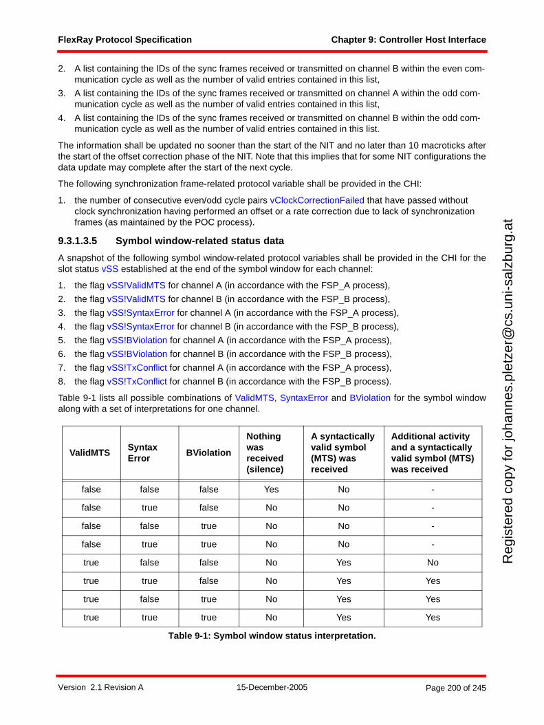
FlexRay Protocol Specification Chapter 9: Controller Host Interface
Reg
iste
red
copy
for
joha
nnes
.ple
tzer
@cs
.uni
-sal
zbur
g.at
2. A list containing the IDs of the sync frames received or transmitted on channel B within the even com-munication cycle as well as the number of valid entries contained in this list,
3. A list containing the IDs of the sync frames received or transmitted on channel A within the odd com-munication cycle as well as the number of valid entries contained in this list,
4. A list containing the IDs of the sync frames received or transmitted on channel B within the odd com-munication cycle as well as the number of valid entries contained in this list.
The information shall be updated no sooner than the start of the NIT and no later than 10 macroticks afterthe start of the offset correction phase of the NIT. Note that this implies that for some NIT configurations thedata update may complete after the start of the next cycle.
The following synchronization frame-related protocol variable shall be provided in the CHI:
1. the number of consecutive even/odd cycle pairs vClockCorrectionFailed that have passed without clock synchronization having performed an offset or a rate correction due to lack of synchronization frames (as maintained by the POC process).
9.3.1.3.5 Symbol window-related status data
A snapshot of the following symbol window-related protocol variables shall be provided in the CHI for theslot status vSS established at the end of the symbol window for each channel:
1. the flag vSS!ValidMTS for channel A (in accordance with the FSP_A process),
2. the flag vSS!ValidMTS for channel B (in accordance with the FSP_B process),
3. the flag vSS!SyntaxError for channel A (in accordance with the FSP_A process),
4. the flag vSS!SyntaxError for channel B (in accordance with the FSP_B process),
5. the flag vSS!BViolation for channel A (in accordance with the FSP_A process),
6. the flag vSS!BViolation for channel B (in accordance with the FSP_B process),
7. the flag vSS!TxConflict for channel A (in accordance with the FSP_A process),
8. the flag vSS!TxConflict for channel B (in accordance with the FSP_B process).
Table 9-1 lists all possible combinations of ValidMTS, SyntaxError and BViolation for the symbol windowalong with a set of interpretations for one channel.
ValidMTSSyntax Error
BViolation
Nothing was received (silence)
A syntactically valid symbol (MTS) was received
Additional activity and a syntactically valid symbol (MTS) was received
false false false Yes No -
false true false No No -
false false true No No -
false true true No No -
true false false No Yes No
true true false No Yes Yes
true false true No Yes Yes
true true true No Yes Yes
Table 9-1: Symbol window status interpretation.
Version 2.1 Revision A 15-December-2005 Page 200 of 245

FlexRay Protocol Specification Chapter 9: Controller Host Interface
Reg
iste
red
copy
for
joha
nnes
.ple
tzer
@cs
.uni
-sal
zbur
g.at
9.3.1.3.6 NIT-related status data
A snapshot of the following NIT-related protocol variables shall be provided in the CHI for the slot statusvSS established at the end of the NIT for each channel:
1. the flag vSS!SyntaxError for channel A (in accordance with the FSP_A process),
2. the flag vSS!SyntaxError for channel B (in accordance with the FSP_B process),
3. the flag vSS!BViolation for channel A (in accordance with the FSP_A process),
4. the flag vSS!BViolation for channel B (in accordance with the FSP_B process).
9.3.1.3.7 Aggregated channel status-related status data
The aggregated channel status provides the host with an accrued status of channel activity for all commu-nication slots regardless of whether they are assigned for transmission or subscribed for reception. Thestatus data is aggregated over a period that is freely definable by the host.
The CHI shall provide indicators for the following channel activity-related events:
1. a channel specific valid frame indicator for channel A that shall be set if one or more valid frames were received in any static or dynamic slot on channel A (i.e. one or more static or dynamic slots had vSS!ValidFrame equal to true) and reset under control of the host,
2. a channel specific valid frame indicator for channel B that shall be set if one or more valid frames were received in any static or dynamic slot on channel B (i.e. one or more static or dynamic slots had vSS!ValidFrame equal to true) and reset under control of the host,
3. a channel specific syntax error indicator for channel A that shall be set if one or more syntax errors were observed on channel A (i.e. one or more static or dynamic slots including symbol window and NIT had vSS!SyntaxError equal to true) and reset under control of the host,
4. a channel specific syntax error indicator for channel B that shall be set if one or more syntax errors were observed on channel B (i.e. one or more static or dynamic slots including symbol window and NIT had vSS!SyntaxError equal to true) and reset under control of the host,
5. a channel specific content error indicator for channel A that shall be set if one or more frames with a content error were received on channel A in any static or dynamic slot (i.e. one or more static or dynamic slots had vSS!ContentError equal to true) and reset under control of the host,
6. a channel specific content error indicator for channel B that shall be set if one or more frames with a content error were received on channel B in any static or dynamic slot (i.e. one or more static or dynamic slots had vSS!ContentError equal to true) and reset under control of the host,
7. a channel specific additional communication indicator for channel A that shall be set if one or more valid frames were received on channel A in slots that also contained any additional communication during the observation period (i.e. one or more slots had vSS!ValidFrame equal to true and any combi-nation of either vSS!SyntaxError equal to true or vSS!ContentError equal to true or vSS!BViolation equal to true) and reset under control of the host,
8. a channel specific additional communication indicator for channel B that shall be set if one or more valid frames were received on channel B in slots that also contained any additional communication during the observation period (i.e. one or more slots had vSS!ValidFrame equal to true and any combi-nation of either vSS!SyntaxError equal to true or vSS!ContentError equal to true or vSS!BViolation equal to true) and reset under control of the host,
9. a channel specific slot boundary indicator for channel A that shall be set if one or more slot boundary violations were observed on channel A (i.e. one or more static or dynamic slots including symbol win-dow and NIT had vSS!BViolation equal to true) and reset under control of the host,
10. a channel specific slot boundary indicator for channel B that shall be set if one or more slot boundary violations were observed on channel B (i.e. one or more static or dynamic slots including symbol win-dow and NIT had vSS!BViolation equal to true) and reset under control of the host.
Version 2.1 Revision A 15-December-2005 Page 201 of 245
FlexRay Protocol Specification Chapter 9: Controller Host Interface
Reg
iste
red
copy
for
joha
nnes
.ple
tzer
@cs
.uni
-sal
zbur
g.at
9.3.1.3.8 Wakeup-related status data
The CHI shall provide indicators for the following wakeup-related events:
1. a wakeup pattern received indicator for channel A that shall be set upon 'set WUP received indicator on A in CHI' (in accordance with the WUPDEC_A process) and reset under control of the host,
2. a wakeup pattern received indicator for channel B that shall be set upon 'set WUP received indicator on B in CHI' (in accordance with the WUPDEC_B process) and reset under control of the host.
9.3.1.3.9 Dynamic segment-related status data
The following dynamic segment-related status variables shall be provided in the CHI:
1. the value of the channel dependent vSlotCounter[A] at the time of the last frame transmission by the node on channel A in the dynamic segment as reflected by the variable zLastDynTxSlot in the MAC_A process. It is updated at the end of the dynamic segment and would have a value of zero if no frame
was transmitted during the dynamic segment,104
2. the value of the channel dependent vSlotCounter[B] at the time of the last frame transmission by the node on channel B in the dynamic segment as reflected by the variable zLastDynTxSlot in the MAC_B process. It is updated at the end of the dynamic segment and would have a value of zero if no frame was transmitted during the dynamic segment.
9.3.2 Message data interfaceThe message data interface addresses the exchange of message data between the host and the FlexRaycommunication protocol within each node. Message transmission pertains to the message data flow fromthe host to the FlexRay communication protocol and message reception pertains to the message data flowfrom the FlexRay communication protocol to the host.
Message transmission as well as message reception has associated message buffer configuration data,message buffer control data, and message buffer status data.
The host shall have read access to message buffer configuration data independently of the protocol state.Host write access to the buffer configuration shall be allowed in the POC:config state, and may be allowedin other POC states.105
9.3.2.1 Message transmission
Message transmission operates on non-queued transmit buffers. A non-queued transmit buffer is a datastorage structure
1. for which the host has access to the data through both a read operation and a write operation,
2. for which the protocol accesses the data through a read operation, and
3. in which new values overwrite former values.
9.3.2.1.1 Transmission slot assignment
A specific TDMA slot in either the static or the dynamic segment shall be assigned to a node by assigningthe corresponding slot ID to the node according to the constraints listed in Chapter 5.
Nodes own a list of assigned slots for each channel. With the exception of the sync slot or the single slotused for single slot mode, the list of assigned slots may be modified during the operation of the cluster. Theassignment of a sync slot / single slot can only be changed during POC:config.
104 This can be used to determine if the frame corresponding to a given slot in the dynamic segment was actually transmitted. This is especially beneficial for continuous transmission mode since then the "frame transmitted" flag is less useful.
105 It is not required that any implementation supports the modification of buffer configuration data in other POC states than the POC:config state.
Version 2.1 Revision A 15-December-2005 Page 202 of 245

FlexRay Protocol Specification Chapter 9: Controller Host Interface
Reg
iste
red
copy
for
joha
nnes
.ple
tzer
@cs
.uni
-sal
zbur
g.at
In the static segment
When a slot occurs, if the slot is assigned to a node on a channel that node must transmit either a normal frame or a null frame on that channel. Specifically, a null frame will be sent if there is no data ready, or if there is no match on a transmit filter (cycle counter filtering, for example).
In the dynamic segment
When a slot occurs, if a slot is assigned to a node on a channel that node only transmits a frame on that channel if there is data ready and there is a match on relevant transmit filters (no null frames are sent).
In both segments
The system designer must ensure that in any given cycle no two nodes transmit in the same slot on the same channel.
It is the intention of the protocol that in the static segment each slot on a channel is owned by exactly onenode (i.e., slot multiplexing is not allowed in the static segment). Slot multiplexing (i.e., different nodesowning a slot in different cycles) is allowed in the dynamic segment, and it is up to the application to ensurethat the previous characteristics are met.
9.3.2.1.2 Transmit buffer assignment
A transmit buffer shall be assigned to a transmission slot based on the slot identifier of the transmission slotand the identifier of the channel on which the transmission shall occur.
In the static segment possible transmit buffer assignments are
1. assignment to channel A, or
2. assignment to channel B, or
3. assignment to channel A and to channel B.
In the dynamic segment possible transmit buffer assignments are
1. assignment to channel A, or
2. assignment to channel B.
Each transmit buffer shall contain the length MessageLength of the message held in the respective transmitbuffer.
Multiple transmit buffers may be assigned to the same communication slot on the same channel. In this caseit shall be possible to identify a transmit buffer for transmission using the value of the cycle counter to whichthe specific communication slot relates.
Each transmit buffer shall be associated with a transmit buffer valid flag106 that denotes whether themessage contained in the transmit buffer is valid or not.
For each transmit buffer the CHI shall ensure that the protocol either
1. is provided with a consistent set of valid message data from the transmit buffer, or
2. receives indication that a consistent read of message data is not possible or that the transmit buffer contains no valid message.
106 The specific mechanism for determining when the information is valid is not specified. For example, the CHI may automatically invalidate the information if it has not been updated by the host within a certain period of time. These features are implementation dependent. It is expected that most implementations will support at least two behaviors - either the message is transmitted exactly once as the result of a buffer update, or a message is transmitted continuously until the host invalidates the buffer.
Version 2.1 Revision A 15-December-2005 Page 203 of 245
FlexRay Protocol Specification Chapter 9: Controller Host Interface
Reg
iste
red
copy
for
joha
nnes
.ple
tzer
@cs
.uni
-sal
zbur
g.at
9.3.2.1.3 Transmit buffer identification for message retrieval
The protocol interacts with the controller host interface by requesting message data at the start of eachcommunication slot according to the media access control processes defined in Chapter 5. The protocolexpects to receive data elements as defined in Definition 5-2.
In response to each request the CHI shall perform the following steps:
1. The CHI shall check whether the slot is assigned to the node on the channel vChannel by querying the slot assignment list using vSlotCounter and vChannel.
2. If the specific communication slot is not assigned to the node then the CHI shall return vTCHI with vTCHI!Assignment set to UNASSIGNED else vTCHI!Assignment shall be set to ASSIGNED and the subsequent steps shall be executed.
3. vTCHI!HeaderCRC shall be set to the value of the header CRC retrieved from the slot assignment list.
4. The transmit buffer shall be identified based on vSlotCounter, vCycleCounter, and vChannel.
5. If no transmit buffer is assigned then the CHI shall signal to the protocol that the communication slot is assigned but without any message data available by setting vTCHI!TxMessageAvailable to false and returning vTCHI.
6. If a transmit buffer is assigned then a consistent read of its data shall be performed.
7. If a consistent read is not possible, i.e. the transmit buffer is blocked by the host, or the transmit buffer valid flag is set to false, then the CHI shall signal to the protocol that the communication slot is assigned but without any message data available by setting vTCHI!TxMessageAvailable to false and returning vTCHI.
8. The CHI shall signal to the protocol that the communication slot is assigned with message data availa-ble by setting
a. vTCHI!TxMessageAvailable to true,
b. vTCHI!PPIndicator to the value retrieved from the transmit buffer associated control data as definedby the message ID filtering service in section 9.3.3.3 and the network management service in section9.3.3.4,
c. vTCHI!Length to the length of the message MessageLength held in the corresponding transmitbuffer,
d. vTCHI!Message to the message data from the transmit buffer
and returning vTCHI.
9.3.2.1.4 Transmit buffer-related status data
The CHI shall provide message status data for each transmission slot that is assigned to the node on a perchannel basis.
For each static and dynamic transmission slot the CHI shall provide the following status data to the host foreach assigned channel:
1. a frame transmitted flag that shall be set to true if message data was provided to the protocol engine
for transmission and set to false by host access,107
2. a syntax error flag that shall be set if a syntax error was observed in the transmission slot (vSS!SyntaxError set to true) or cleared if no syntax error was observed in the transmission slot (vSS!SyntaxError set to false),
107 Access by host can mean: resetting the frame transmitted flag directly; resetting it as a consequence of access to another flag, e.g. "transmit buffer valid" flag; or by write access to the payload data itself.
Version 2.1 Revision A 15-December-2005 Page 204 of 245
FlexRay Protocol Specification Chapter 9: Controller Host Interface
Reg
iste
red
copy
for
joha
nnes
.ple
tzer
@cs
.uni
-sal
zbur
g.at
3. a content error flag that shall be set if a content error was observed in the transmission slot (vSS!ContentError set to true) or cleared if no content error was observed in the transmission slot (vSS!ContentError set to false),
4. a slot boundary violation flag that shall be set if a slot boundary violation, i.e. channel active at the start or at the end of the slot, was observed in the transmission slot (vSS!BViolation set to true) or cleared if no slot boundary violation was observed in the transmission slot (vSS!BViolation set to false),
5. a transmission conflict flag that shall be set if a transmission conflict error was observed in the trans-mission slot (vSS!TxConflict set to true) or cleared if no transmission conflict error was observed in the transmission slot (vSS!TxConflict set to false),
6. a valid frame flag that shall be set if a valid frame was received in the transmission slot (vSS!ValidFrame set to true) or cleared if no valid frame was received in the transmission slot (vSS!ValidFrame set to false).
9.3.2.2 Message reception
Message reception operates on queued and/or non-queued receive buffers. A non-queued receive bufferis a data storage structure
1. for which the host has access to the data through a read operation,
2. for which the protocol engine has access to the data through a write operation, and
3. in which new values overwrite former values.
A queued receive buffer is a data storage structure
1. for which the host has access to the data through a read operation,
2. for which the protocol engine has access to the data through a write operation, and
3. in which new values are queued behind former values.
9.3.2.2.1 Reception slot subscription and receive buffer assignment
For each communication slot the protocol provides a tuple of values to the CHI consisting of a slot statusvSS, and the contents of the first semantically valid frame vRF that was received in the communication slot,if a semantically valid frame was received in the corresponding communication slot. Different mechanismswithin the CHI define how a specific receive buffer is selected based on this tuple.
In general, a receive buffer may be identified using one or more of the following selection criteria:108
1. the slot identifier vSS!SlotCount of the communication slot to which the tuple relates,
2. the channel identifier vSS!Channel of the communication slot to which the tuple relates,
3. the cycle counter vSS!CycleCount of the communication slot to which the tuple relates.
For frames received in the static segment, one or more of the following channel assignments may besupported:
1. receive buffer assigned to channel A, or,
2. receive buffer assigned to channel B, or
3. receive buffer assigned to both channel A and channel B. In this case the receive buffer shall contain the first semantically valid frame received on either channel A or on channel B within the correspond-ing slot.
For frames received in the dynamic segment, one or more of the following channel assignments shall besupported:
1. receive buffer assigned to channel A, or,
108 An additional optional selection criteria based on message ID filtering is specified in section 9.3.3.3.
Version 2.1 Revision A 15-December-2005 Page 205 of 245
FlexRay Protocol Specification Chapter 9: Controller Host Interface
Reg
iste
red
copy
for
joha
nnes
.ple
tzer
@cs
.uni
-sal
zbur
g.at
2. receive buffer assigned to channel B.
For each receive buffer the CHI shall ensure that the host either
1. is provided with a consistent set of message data from the receive buffer, or,
2. receives indication that a consistent read of its data is not possible.
For each receive buffer the CHI shall ensure that the protocol is able to write to the corresponding receivebuffer either
1. consistently, i.e. perform a consistent write of its data as if in one indivisible operation, or
2. not at all. In this case a flag shall be provided through which the host can assess that receive buffer contents were lost.
Each receive buffer shall hold up to a buffer specific bound number of two-byte words.
For non-queued receive buffers this buffer specific bound may be set individually for each receive bufferwithin a node between 1 and cPayloadLengthMax.
9.3.2.2.2 Receive buffer contents
Each receive buffer shall contain slot status-related data as well as frame contents-related data.
9.3.2.2.2.1 Slot status-related data
A snapshot of the following slot status-related protocol variables shall be provided in the CHI for eachassigned receive buffer at the end of the respective communication slot:
1. the valid frame flag vSS!ValidFrame (in accordance with the corresponding channel-specific FSP proc-ess),
2. the syntax error flag vSS!SyntaxError (in accordance with the corresponding channel-specific FSP process),
3. the content error flag vSS!ContentError (in accordance with the corresponding channel-specific FSP process),
4. the boundary violation flag vSS!BViolation (in accordance with the corresponding channel-specific FSP process).
In addition a snapshot of the following status data shall be provided within an assigned receive buffer if areceive buffer is assigned to both channel A and channel B:
1. the enumeration vSS!Channel (in accordance with the corresponding channel-specific FSP process) to identify the channel on which the frame was received.
A snapshot of the following slot status-related protocol variables shall be provided in the CHI for eachassigned receive buffer at the end of the respective communication slot if a valid frame was received in therespective slot:
1. the flag vRF!Header!NFIndicator (in accordance with the corresponding channel-specific FSP proc-ess),
2. the flag vRF!Header!PPIndicator (in accordance with the corresponding channel-specific FSP proc-ess).
Table 9-2 lists all possible combinations of ValidFrame, SyntaxError, ContentError and BViolation for thestatic and the dynamic segment along with a set of interpretations concerning the number of syntactically109
and semantically110 valid frames received in a static or dynamic slot, respectively.
109 A frame is syntactically valid if it fulfills the decoding rules defined in section 3.3.5 including the check for a valid header CRC and a valid frame CRC in accordance with the number of two-byte payload words as denoted in the header of the frame.
110 A semantically valid frame is a syntactically valid frame that also fulfils a set of content related criteria.
Version 2.1 Revision A 15-December-2005 Page 206 of 245
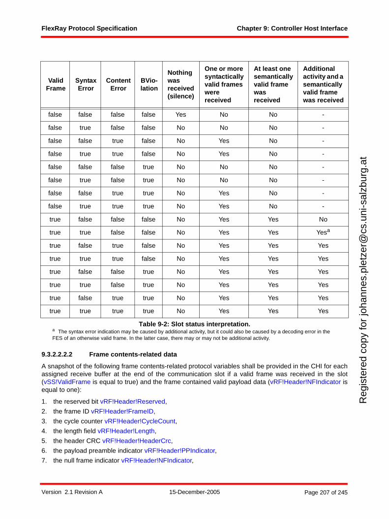
FlexRay Protocol Specification Chapter 9: Controller Host Interface
Reg
iste
red
copy
for
joha
nnes
.ple
tzer
@cs
.uni
-sal
zbur
g.at
9.3.2.2.2.2 Frame contents-related data
A snapshot of the following frame contents-related protocol variables shall be provided in the CHI for eachassigned receive buffer at the end of the communication slot if a valid frame was received in the slot(vSS!ValidFrame is equal to true) and the frame contained valid payload data (vRF!Header!NFIndicator isequal to one):
1. the reserved bit vRF!Header!Reserved,
2. the frame ID vRF!Header!FrameID,
3. the cycle counter vRF!Header!CycleCount,
4. the length field vRF!Header!Length,
5. the header CRC vRF!Header!HeaderCrc,
6. the payload preamble indicator vRF!Header!PPIndicator,
7. the null frame indicator vRF!Header!NFIndicator,
Valid Frame
Syntax Error
Content Error
BVio-lation
Nothing was received (silence)
One or more syntactically valid frames were received
At least one semantically valid frame was received
Additional activity and a semantically valid frame was received
false false false false Yes No No -
false true false false No No No -
false false true false No Yes No -
false true true false No Yes No -
false false false true No No No -
false true false true No No No -
false false true true No Yes No -
false true true true No Yes No -
true false false false No Yes Yes No
true true false false No Yes Yes Yesa
a The syntax error indication may be caused by additional activity, but it could also be caused by a decoding error in the FES of an otherwise valid frame. In the latter case, there may or may not be additional activity.
true false true false No Yes Yes Yes
true true true false No Yes Yes Yes
true false false true No Yes Yes Yes
true true false true No Yes Yes Yes
true false true true No Yes Yes Yes
true true true true No Yes Yes Yes
Table 9-2: Slot status interpretation.
Version 2.1 Revision A 15-December-2005 Page 207 of 245

FlexRay Protocol Specification Chapter 9: Controller Host Interface
Reg
iste
red
copy
for
joha
nnes
.ple
tzer
@cs
.uni
-sal
zbur
g.at
8. the sync frame indicator vRF!Header!SyFIndicator,
9. the startup frame indicator vRF!Header!SuFIndicator,
10. vRF!Header!Length number of two-byte payload data words from vRF!Payload, if vRF!Header!Length does not exceed the buffer length BufferLength of the assigned receive buffer,
11. BufferLength number of two-byte payload data words from vRF!Payload, if vRF!Header!Length
exceeds the buffer length BufferLength of the assigned receive buffer.111
9.3.3 CHI Services
9.3.3.1 Macrotick timer service
9.3.3.1.1 Absolute timers
The node shall provide at least one absolute timer that may be set to an absolute time in terms of cyclecount and macrotick, i.e. the timer is set to expire at a determined macrotick in a determined communicationcycle.
It shall be possible to activate an absolute timer as long as the protocol is in either the POC:normal activestate or the POC:normal passive state.
All absolute timers shall be deactivated when the protocol leaves the POC:normal active state or thePOC:normal passive state apart from transitions between the POC:normal active state and the POC:normalpassive state.
9.3.3.1.2 Relative timers
The node may provide one or more relative timers that may be set to a relative time in terms of macrotick.112
It shall be possible to activate a relative timer as long as the protocol is in either the POC:normal active stateor the POC:normal passive state.
All relative timers shall be deactivated when the protocol leaves the POC:normal active state or thePOC:normal passive state apart from transitions between the POC:normal active state and the POC:normalpassive state.
9.3.3.2 Interrupt service
The interrupt service provides a configurable interrupt mechanism to the host based on a set of interruptsources.
It shall be possible for the host to enable and disable each interrupt individually.
It shall be possible for the host to enable and disable all interrupts without having to enable or disable eachinterrupt individually.
It shall be possible for the host to clear each interrupt individually.
An interrupt status shall be provided that reflects the status of each interrupt regardless of whether theinterrupt is enabled or disabled.
At least one interrupt request shall be available that is raised when a timer has elapsed.
111 The host can assess such a truncation through the data element vRF!Header!Length.112 The exact behavior of the relative timer is implementation specific. In particular, the point at which the timer begins to
decrement may vary from implementation to implementation. Also note that the duration of a macrotick varies from macrotick to macrotick, especially during the offset correction phase. As a result, the duration of a relative timer can vary substantially depending on when in the cycle it is activated.
Version 2.1 Revision A 15-December-2005 Page 208 of 245

FlexRay Protocol Specification Chapter 9: Controller Host Interface
Reg
iste
red
copy
for
joha
nnes
.ple
tzer
@cs
.uni
-sal
zbur
g.at
9.3.3.3 Message ID filtering service
The message ID filtering service provides means for selecting receive buffers based on a message ID thatmay be exchanged in the first two bytes of the payload segment of selected frames.
Support for the message ID filtering service by a particular device is optional.
Message ID filtering is performed by exchanging a message ID in selected message ID enabled frameswithin the dynamic segment of the communication cycle that have the payload preamble indicator set to onein the header of the frame.
To support this service minimally the following data needs to be maintained by the CHI:
1. The message buffer control data shall hold the payload preamble indicator for each transmit buffer so that the host can configure whether the message contains a message ID or not. If no message ID serv-ice is supported then the CHI shall provide a payload preamble indicator value of zero to the protocol for all transmit buffers that are assigned to the dynamic segment.
2. The message buffer configuration data shall hold a message ID filter for each receive buffer that is involved with message ID filtering.
For each semantically valid frame that was received in the dynamic segment of the communication cycleand that contains a message ID the CHI shall apply this message ID as an additional selection criteria forreceive buffer identification.
9.3.3.4 Network management service
The network management service provides means for exchanging and processing network managementdata. This service supports high-level host-based network management protocols that provide cluster-widecoordination of startup and shutdown decisions based on the actual application state.
Support for the network management service by a particular device is optional.
Network management is performed by exchanging a network management vector in selected networkmanagement enabled frames within the static segment of the communication cycle that have the payloadpreamble indicator set to one in the header of the frame.
To support this service minimally the following data needs to be maintained by the CHI:
1. The protocol configuration data shall contain the number of bytes gNetworkManagementVectorLength contained in the network management vector.
2. The message buffer control data shall hold the payload preamble indicator for each transmit buffer so that the host can configure whether the message contains a network management vector or not. If no network management service is supported then the CHI shall provide a payload preamble indicator value of zero to the protocol for all transmit buffers that are assigned to the static segment.
Throughout each communication cycle the CHI shall maintain an accrued network management vector byapplying a bit-wise OR between each network management vector received on each channel (regardlessof whether the frame is subscribed to a receive buffer) and the accrued network management vector.
1. The protocol status data shall contain a snapshot of the accrued network management vector that shall be updated at the end of each communication cycle and shall remain available until it is overwrit-ten by the next snapshot at the end of the subsequent communication cycle as long as the protocol is in either the POC:normal active state or the POC:normal passive state.
In addition to the capabilities provided above, it is also possible for implementers to provide additional typesof Network Management Services, for example, providing direct (non-OR'd) access to the NM Vector data.
Version 2.1 Revision A 15-December-2005 Page 209 of 245
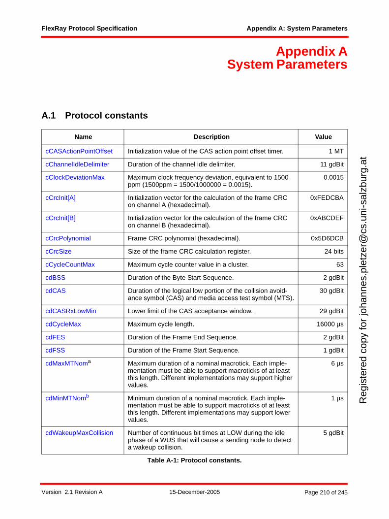
FlexRay Protocol Specification Appendix A: System Parameters
Reg
iste
red
copy
for
joha
nnes
.ple
tzer
@cs
.uni
-sal
zbur
g.at
Appendix ASystem Parameters
A.1 Protocol constants
Name Description Value
cCASActionPointOffset Initialization value of the CAS action point offset timer. 1 MT
cChannelIdleDelimiter Duration of the channel idle delimiter. 11 gdBit
cClockDeviationMax Maximum clock frequency deviation, equivalent to 1500 ppm (1500ppm = 1500/1000000 = 0.0015).
0.0015
cCrcInit[A] Initialization vector for the calculation of the frame CRC on channel A (hexadecimal).
0xFEDCBA
cCrcInit[B] Initialization vector for the calculation of the frame CRC on channel B (hexadecimal).
0xABCDEF
cCrcPolynomial Frame CRC polynomial (hexadecimal). 0x5D6DCB
cCrcSize Size of the frame CRC calculation register. 24 bits
cCycleCountMax Maximum cycle counter value in a cluster. 63
cdBSS Duration of the Byte Start Sequence. 2 gdBit
cdCAS Duration of the logical low portion of the collision avoid-ance symbol (CAS) and media access test symbol (MTS).
30 gdBit
cdCASRxLowMin Lower limit of the CAS acceptance window. 29 gdBit
cdCycleMax Maximum cycle length. 16000 µs
cdFES Duration of the Frame End Sequence. 2 gdBit
cdFSS Duration of the Frame Start Sequence. 1 gdBit
cdMaxMTNoma Maximum duration of a nominal macrotick. Each imple-mentation must be able to support macroticks of at least this length. Different implementations may support higher values.
6 µs
cdMinMTNomb Minimum duration of a nominal macrotick. Each imple-mentation must be able to support macroticks of at least this length. Different implementations may support lower values.
1 µs
cdWakeupMaxCollision Number of continuous bit times at LOW during the idle phase of a WUS that will cause a sending node to detect a wakeup collision.
5 gdBit
Table A-1: Protocol constants.
Version 2.1 Revision A 15-December-2005 Page 210 of 245
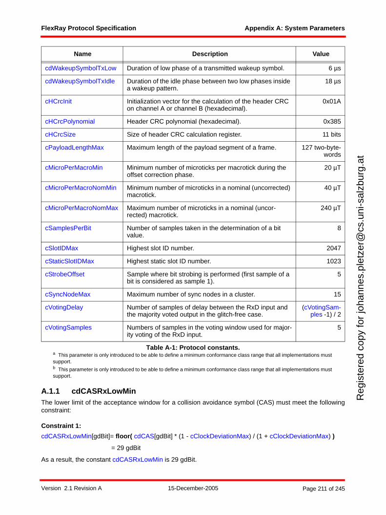
FlexRay Protocol Specification Appendix A: System Parameters
Reg
iste
red
copy
for
joha
nnes
.ple
tzer
@cs
.uni
-sal
zbur
g.at
A.1.1 cdCASRxLowMinThe lower limit of the acceptance window for a collision avoidance symbol (CAS) must meet the followingconstraint:
Constraint 1:
cdCASRxLowMin[gdBit]= floor( cdCAS[gdBit] * (1 - cClockDeviationMax) / (1 + cClockDeviationMax) )
= 29 gdBit
As a result, the constant cdCASRxLowMin is 29 gdBit.
cdWakeupSymbolTxLow Duration of low phase of a transmitted wakeup symbol. 6 µs
cdWakeupSymbolTxIdle Duration of the idle phase between two low phases inside a wakeup pattern.
18 µs
cHCrcInit Initialization vector for the calculation of the header CRC on channel A or channel B (hexadecimal).
0x01A
cHCrcPolynomial Header CRC polynomial (hexadecimal). 0x385
cHCrcSize Size of header CRC calculation register. 11 bits
cPayloadLengthMax Maximum length of the payload segment of a frame. 127 two-byte-words
cMicroPerMacroMin Minimum number of microticks per macrotick during the offset correction phase.
20 µT
cMicroPerMacroNomMin Minimum number of microticks in a nominal (uncorrected) macrotick.
40 µT
cMicroPerMacroNomMax Maximum number of microticks in a nominal (uncor-rected) macrotick.
240 µT
cSamplesPerBit Number of samples taken in the determination of a bit value.
8
cSlotIDMax Highest slot ID number. 2047
cStaticSlotIDMax Highest static slot ID number. 1023
cStrobeOffset Sample where bit strobing is performed (first sample of a bit is considered as sample 1).
5
cSyncNodeMax Maximum number of sync nodes in a cluster. 15
cVotingDelay Number of samples of delay between the RxD input and the majority voted output in the glitch-free case.
(cVotingSam-ples -1) / 2
cVotingSamples Numbers of samples in the voting window used for major-ity voting of the RxD input.
5
a This parameter is only introduced to be able to define a minimum conformance class range that all implementations must support.b This parameter is only introduced to be able to define a minimum conformance class range that all implementations must support.
Name Description Value
Table A-1: Protocol constants.
Version 2.1 Revision A 15-December-2005 Page 211 of 245
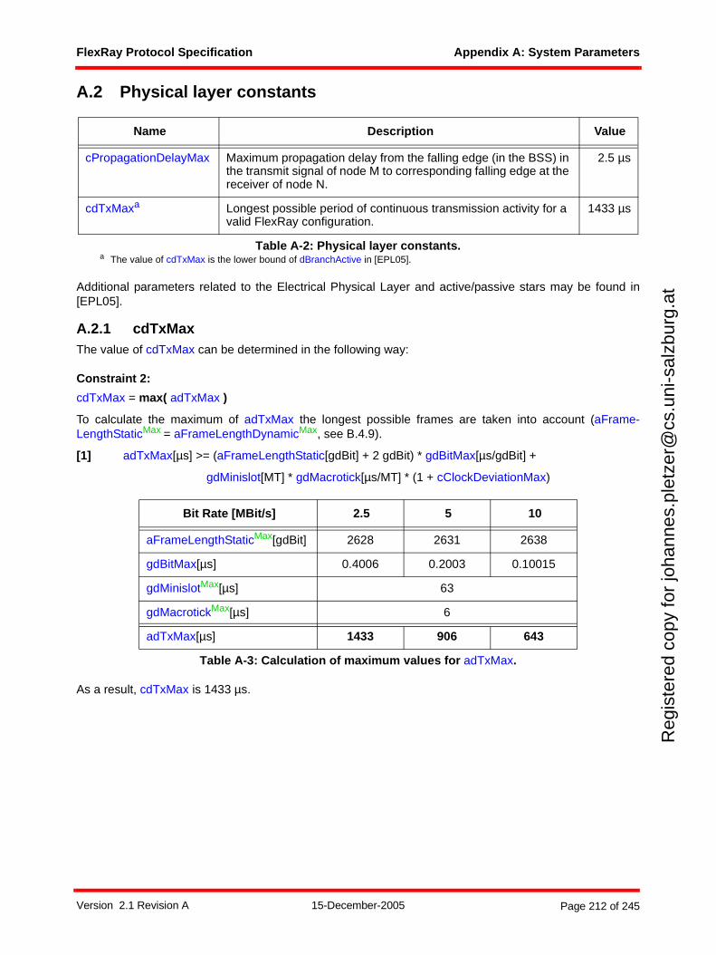
FlexRay Protocol Specification Appendix A: System Parameters
Reg
iste
red
copy
for
joha
nnes
.ple
tzer
@cs
.uni
-sal
zbur
g.at
A.2 Physical layer constants
Additional parameters related to the Electrical Physical Layer and active/passive stars may be found in[EPL05].
A.2.1 cdTxMaxThe value of cdTxMax can be determined in the following way:
Constraint 2:
cdTxMax = max( adTxMax )
To calculate the maximum of adTxMax the longest possible frames are taken into account (aFrame-LengthStaticMax = aFrameLengthDynamicMax, see B.4.9).
[1] adTxMax[µs] >= (aFrameLengthStatic[gdBit] + 2 gdBit) * gdBitMax[µs/gdBit] +
gdMinislot[MT] * gdMacrotick[µs/MT] * (1 + cClockDeviationMax)
As a result, cdTxMax is 1433 µs.
Name Description Value
cPropagationDelayMax Maximum propagation delay from the falling edge (in the BSS) in the transmit signal of node M to corresponding falling edge at the receiver of node N.
2.5 µs
cdTxMaxa
a The value of cdTxMax is the lower bound of dBranchActive in [EPL05].
Longest possible period of continuous transmission activity for a valid FlexRay configuration.
1433 µs
Table A-2: Physical layer constants.
Bit Rate [MBit/s] 2.5 5 10
aFrameLengthStaticMax[gdBit] 2628 2631 2638
gdBitMax[µs] 0.4006 0.2003 0.10015
gdMinislotMax[µs] 63
gdMacrotickMax[µs] 6
adTxMax[µs] 1433 906 643
Table A-3: Calculation of maximum values for adTxMax.
Version 2.1 Revision A 15-December-2005 Page 212 of 245
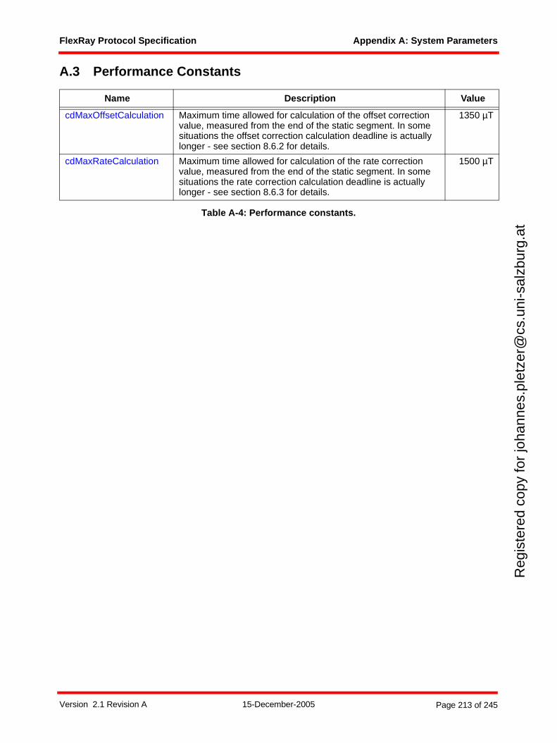
FlexRay Protocol Specification Appendix A: System Parameters
Reg
iste
red
copy
for
joha
nnes
.ple
tzer
@cs
.uni
-sal
zbur
g.at
A.3 Performance Constants
Table A-4: Performance constants.
Name Description Value
cdMaxOffsetCalculation Maximum time allowed for calculation of the offset correction value, measured from the end of the static segment. In some situations the offset correction calculation deadline is actually longer - see section 8.6.2 for details.
1350 µT
cdMaxRateCalculation Maximum time allowed for calculation of the rate correction value, measured from the end of the static segment. In some situations the rate correction calculation deadline is actually longer - see section 8.6.3 for details.
1500 µT
Version 2.1 Revision A 15-December-2005 Page 213 of 245
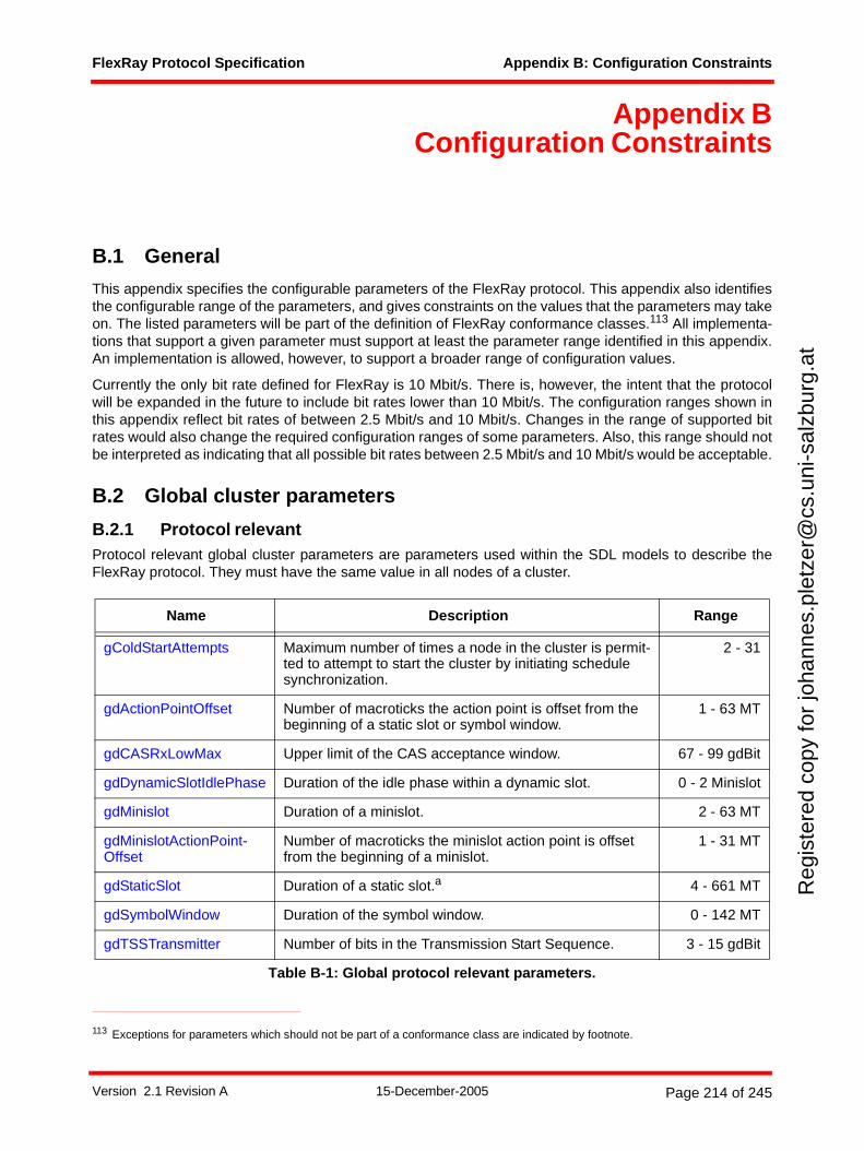
FlexRay Protocol Specification Appendix B: Configuration Constraints
Reg
iste
red
copy
for
joha
nnes
.ple
tzer
@cs
.uni
-sal
zbur
g.at
Appendix BConfiguration Constraints
B.1 General
This appendix specifies the configurable parameters of the FlexRay protocol. This appendix also identifiesthe configurable range of the parameters, and gives constraints on the values that the parameters may takeon. The listed parameters will be part of the definition of FlexRay conformance classes.113 All implementa-tions that support a given parameter must support at least the parameter range identified in this appendix.An implementation is allowed, however, to support a broader range of configuration values.
Currently the only bit rate defined for FlexRay is 10 Mbit/s. There is, however, the intent that the protocolwill be expanded in the future to include bit rates lower than 10 Mbit/s. The configuration ranges shown inthis appendix reflect bit rates of between 2.5 Mbit/s and 10 Mbit/s. Changes in the range of supported bitrates would also change the required configuration ranges of some parameters. Also, this range should notbe interpreted as indicating that all possible bit rates between 2.5 Mbit/s and 10 Mbit/s would be acceptable.
B.2 Global cluster parameters
B.2.1 Protocol relevant Protocol relevant global cluster parameters are parameters used within the SDL models to describe theFlexRay protocol. They must have the same value in all nodes of a cluster.
113 Exceptions for parameters which should not be part of a conformance class are indicated by footnote.
Name Description Range
gColdStartAttempts Maximum number of times a node in the cluster is permit-ted to attempt to start the cluster by initiating schedule synchronization.
2 - 31
gdActionPointOffset Number of macroticks the action point is offset from the beginning of a static slot or symbol window.
1 - 63 MT
gdCASRxLowMax Upper limit of the CAS acceptance window. 67 - 99 gdBit
gdDynamicSlotIdlePhase Duration of the idle phase within a dynamic slot. 0 - 2 Minislot
gdMinislot Duration of a minislot. 2 - 63 MT
gdMinislotActionPoint-Offset
Number of macroticks the minislot action point is offset from the beginning of a minislot.
1 - 31 MT
gdStaticSlot Duration of a static slot.a 4 - 661 MT
gdSymbolWindow Duration of the symbol window. 0 - 142 MT
gdTSSTransmitter Number of bits in the Transmission Start Sequence. 3 - 15 gdBit
Table B-1: Global protocol relevant parameters.
Version 2.1 Revision A 15-December-2005 Page 214 of 245
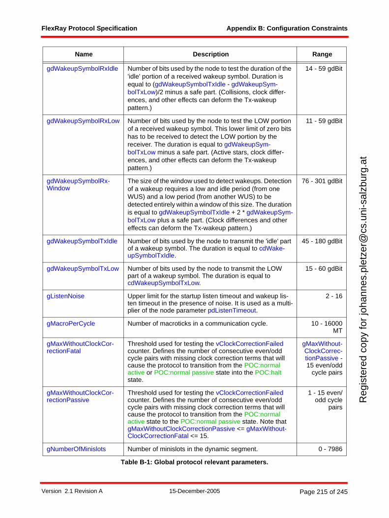
FlexRay Protocol Specification Appendix B: Configuration Constraints
Reg
iste
red
copy
for
joha
nnes
.ple
tzer
@cs
.uni
-sal
zbur
g.at
gdWakeupSymbolRxIdle Number of bits used by the node to test the duration of the 'idle' portion of a received wakeup symbol. Duration is equal to (gdWakeupSymbolTxIdle - gdWakeupSym-bolTxLow)/2 minus a safe part. (Collisions, clock differ-ences, and other effects can deform the Tx-wakeup pattern.)
14 - 59 gdBit
gdWakeupSymbolRxLow Number of bits used by the node to test the LOW portion of a received wakeup symbol. This lower limit of zero bits has to be received to detect the LOW portion by the receiver. The duration is equal to gdWakeupSym-bolTxLow minus a safe part. (Active stars, clock differ-ences, and other effects can deform the Tx-wakeup pattern.)
11 - 59 gdBit
gdWakeupSymbolRx-Window
The size of the window used to detect wakeups. Detection of a wakeup requires a low and idle period (from one WUS) and a low period (from another WUS) to be detected entirely within a window of this size. The duration is equal to gdWakeupSymbolTxIdle + 2 * gdWakeupSym-bolTxLow plus a safe part. (Clock differences and other effects can deform the Tx-wakeup pattern.)
76 - 301 gdBit
gdWakeupSymbolTxIdle Number of bits used by the node to transmit the 'idle' part of a wakeup symbol. The duration is equal to cdWake-upSymbolTxIdle.
45 - 180 gdBit
gdWakeupSymbolTxLow Number of bits used by the node to transmit the LOW part of a wakeup symbol. The duration is equal to cdWakeupSymbolTxLow.
15 - 60 gdBit
gListenNoise Upper limit for the startup listen timeout and wakeup lis-ten timeout in the presence of noise. It is used as a multi-plier of the node parameter pdListenTimeout.
2 - 16
gMacroPerCycle Number of macroticks in a communication cycle. 10 - 16000MT
gMaxWithoutClockCor-rectionFatal
Threshold used for testing the vClockCorrectionFailed counter. Defines the number of consecutive even/odd cycle pairs with missing clock correction terms that will cause the protocol to transition from the POC:normal active or POC:normal passive state into the POC:halt state.
gMaxWithout-ClockCorrec-tionPassive -15 even/odd
cycle pairs
gMaxWithoutClockCor-rectionPassive
Threshold used for testing the vClockCorrectionFailed counter. Defines the number of consecutive even/odd cycle pairs with missing clock correction terms that will cause the protocol to transition from the POC:normal active state to the POC:normal passive state. Note that gMaxWithoutClockCorrectionPassive <= gMaxWithout-ClockCorrectionFatal <= 15.
1 - 15 even/odd cycle
pairs
gNumberOfMinislots Number of minislots in the dynamic segment. 0 - 7986
Name Description Range
Table B-1: Global protocol relevant parameters.
Version 2.1 Revision A 15-December-2005 Page 215 of 245
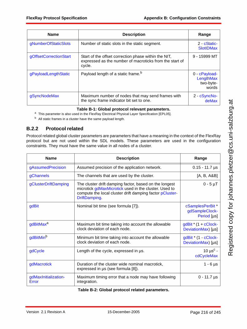
FlexRay Protocol Specification Appendix B: Configuration Constraints
Reg
iste
red
copy
for
joha
nnes
.ple
tzer
@cs
.uni
-sal
zbur
g.at
B.2.2 Protocol relatedProtocol related global cluster parameters are parameters that have a meaning in the context of the FlexRayprotocol but are not used within the SDL models. These parameters are used in the configurationconstraints. They must have the same value in all nodes of a cluster.
gNumberOfStaticSlots Number of static slots in the static segment. 2 - cStatic-SlotIDMax
gOffsetCorrectionStart Start of the offset correction phase within the NIT, expressed as the number of macroticks from the start of cycle.
9 - 15999 MT
gPayloadLengthStatic Payload length of a static frame.b 0 - cPayload-LengthMax
two-byte-words
gSyncNodeMax Maximum number of nodes that may send frames with the sync frame indicator bit set to one.
2 - cSyncNo-deMax
a This parameter is also used in the FlexRay Electrical Physical Layer Specification [EPL05].b All static frames in a cluster have the same payload length.
Name Description Range
gAssumedPrecision Assumed precision of the application network. 0.15 - 11.7 µs
gChannels The channels that are used by the cluster. [A, B, A&B]
gClusterDriftDamping The cluster drift damping factor, based on the longest microtick gdMaxMicrotick used in the cluster. Used to compute the local cluster drift damping factor pCluster-DriftDamping.
0 - 5 µT
gdBit Nominal bit time (see formula [7]). cSamplesPerBit *gdSampleClock-
Period [µs]
gdBitMaxa Maximum bit time taking into account the allowable clock deviation of each node.
gdBit * (1 + cClock-DeviationMax) [µs]
gdBitMinb Minimum bit time taking into account the allowable clock deviation of each node.
gdBit * (1 - cClock-DeviationMax) [µs]
gdCycle Length of the cycle, expressed in µs. 10 µsc -cdCycleMax
gdMacrotick Duration of the cluster wide nominal macrotick, expressed in µs (see formula [8]).
1 - 6 µs
gdMaxInitialization-Error
Maximum timing error that a node may have following integration.
0 - 11.7 µs
Table B-2: Global protocol related parameters.
Name Description Range
Table B-1: Global protocol relevant parameters.
Version 2.1 Revision A 15-December-2005 Page 216 of 245
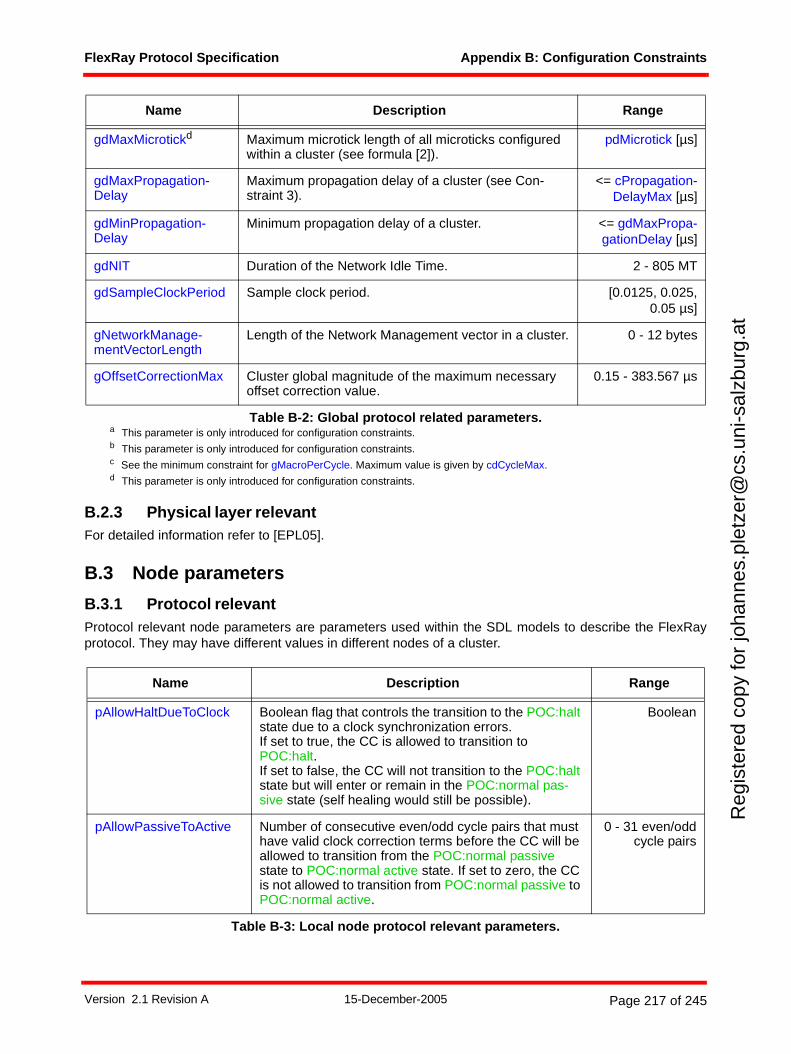
FlexRay Protocol Specification Appendix B: Configuration Constraints
Reg
iste
red
copy
for
joha
nnes
.ple
tzer
@cs
.uni
-sal
zbur
g.at
B.2.3 Physical layer relevantFor detailed information refer to [EPL05].
B.3 Node parameters
B.3.1 Protocol relevantProtocol relevant node parameters are parameters used within the SDL models to describe the FlexRayprotocol. They may have different values in different nodes of a cluster.
gdMaxMicrotickd Maximum microtick length of all microticks configured within a cluster (see formula [2]).
pdMicrotick [µs]
gdMaxPropagation-Delay
Maximum propagation delay of a cluster (see Con-straint 3).
<= cPropagation-DelayMax [µs]
gdMinPropagation-Delay
Minimum propagation delay of a cluster. <= gdMaxPropa-gationDelay [µs]
gdNIT Duration of the Network Idle Time. 2 - 805 MT
gdSampleClockPeriod Sample clock period. [0.0125, 0.025,0.05 µs]
gNetworkManage-mentVectorLength
Length of the Network Management vector in a cluster. 0 - 12 bytes
gOffsetCorrectionMax Cluster global magnitude of the maximum necessary offset correction value.
0.15 - 383.567 µs
a This parameter is only introduced for configuration constraints.b This parameter is only introduced for configuration constraints.c See the minimum constraint for gMacroPerCycle. Maximum value is given by cdCycleMax.d This parameter is only introduced for configuration constraints.
Name Description Range
pAllowHaltDueToClock Boolean flag that controls the transition to the POC:halt state due to a clock synchronization errors. If set to true, the CC is allowed to transition to POC:halt.If set to false, the CC will not transition to the POC:halt state but will enter or remain in the POC:normal pas-sive state (self healing would still be possible).
Boolean
pAllowPassiveToActive Number of consecutive even/odd cycle pairs that must have valid clock correction terms before the CC will be allowed to transition from the POC:normal passive state to POC:normal active state. If set to zero, the CC is not allowed to transition from POC:normal passive to POC:normal active.
0 - 31 even/oddcycle pairs
Table B-3: Local node protocol relevant parameters.
Name Description Range
Table B-2: Global protocol related parameters.
Version 2.1 Revision A 15-December-2005 Page 217 of 245
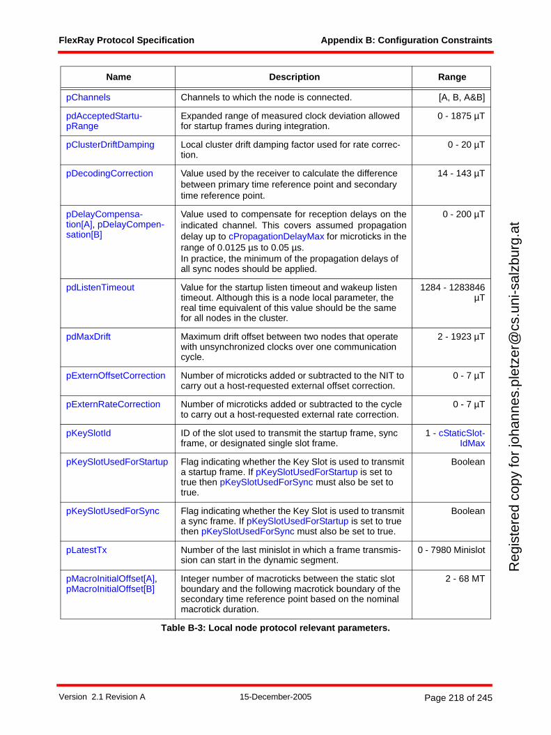
FlexRay Protocol Specification Appendix B: Configuration Constraints
Reg
iste
red
copy
for
joha
nnes
.ple
tzer
@cs
.uni
-sal
zbur
g.at
pChannels Channels to which the node is connected. [A, B, A&B]
pdAcceptedStartu-pRange
Expanded range of measured clock deviation allowed for startup frames during integration.
0 - 1875 µT
pClusterDriftDamping Local cluster drift damping factor used for rate correc-tion.
0 - 20 µT
pDecodingCorrection Value used by the receiver to calculate the difference between primary time reference point and secondary time reference point.
14 - 143 µT
pDelayCompensa-tion[A], pDelayCompen-sation[B]
Value used to compensate for reception delays on theindicated channel. This covers assumed propagationdelay up to cPropagationDelayMax for microticks in therange of 0.0125 µs to 0.05 µs.In practice, the minimum of the propagation delays of all sync nodes should be applied.
0 - 200 µT
pdListenTimeout Value for the startup listen timeout and wakeup listen timeout. Although this is a node local parameter, the real time equivalent of this value should be the same for all nodes in the cluster.
1284 - 1283846µT
pdMaxDrift Maximum drift offset between two nodes that operate with unsynchronized clocks over one communication cycle.
2 - 1923 µT
pExternOffsetCorrection Number of microticks added or subtracted to the NIT to carry out a host-requested external offset correction.
0 - 7 µT
pExternRateCorrection Number of microticks added or subtracted to the cycle to carry out a host-requested external rate correction.
0 - 7 µT
pKeySlotId ID of the slot used to transmit the startup frame, sync frame, or designated single slot frame.
1 - cStaticSlot-IdMax
pKeySlotUsedForStartup Flag indicating whether the Key Slot is used to transmit a startup frame. If pKeySlotUsedForStartup is set to true then pKeySlotUsedForSync must also be set to true.
Boolean
pKeySlotUsedForSync Flag indicating whether the Key Slot is used to transmit a sync frame. If pKeySlotUsedForStartup is set to true then pKeySlotUsedForSync must also be set to true.
Boolean
pLatestTx Number of the last minislot in which a frame transmis-sion can start in the dynamic segment.
0 - 7980 Minislot
pMacroInitialOffset[A],pMacroInitialOffset[B]
Integer number of macroticks between the static slot boundary and the following macrotick boundary of the secondary time reference point based on the nominal macrotick duration.
2 - 68 MT
Name Description Range
Table B-3: Local node protocol relevant parameters.
Version 2.1 Revision A 15-December-2005 Page 218 of 245
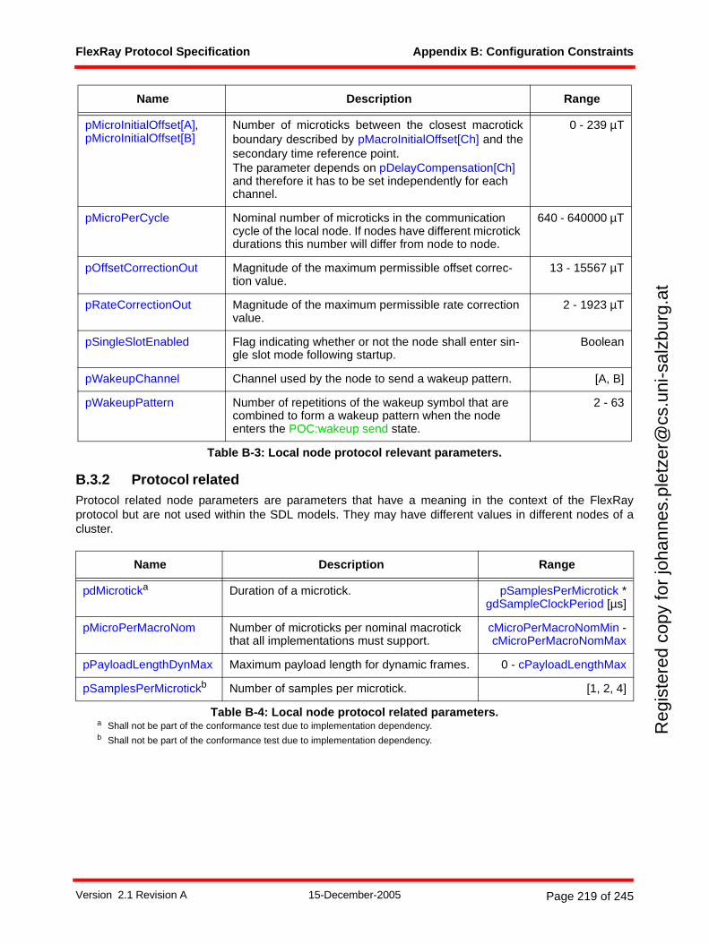
FlexRay Protocol Specification Appendix B: Configuration Constraints
Reg
iste
red
copy
for
joha
nnes
.ple
tzer
@cs
.uni
-sal
zbur
g.at
B.3.2 Protocol relatedProtocol related node parameters are parameters that have a meaning in the context of the FlexRayprotocol but are not used within the SDL models. They may have different values in different nodes of acluster.
pMicroInitialOffset[A], pMicroInitialOffset[B]
Number of microticks between the closest macrotickboundary described by pMacroInitialOffset[Ch] and thesecondary time reference point.The parameter depends on pDelayCompensation[Ch] and therefore it has to be set independently for each channel.
0 - 239 µT
pMicroPerCycle Nominal number of microticks in the communication cycle of the local node. If nodes have different microtick durations this number will differ from node to node.
640 - 640000 µT
pOffsetCorrectionOut Magnitude of the maximum permissible offset correc-tion value.
13 - 15567 µT
pRateCorrectionOut Magnitude of the maximum permissible rate correction value.
2 - 1923 µT
pSingleSlotEnabled Flag indicating whether or not the node shall enter sin-gle slot mode following startup.
Boolean
pWakeupChannel Channel used by the node to send a wakeup pattern. [A, B]
pWakeupPattern Number of repetitions of the wakeup symbol that are combined to form a wakeup pattern when the node enters the POC:wakeup send state.
2 - 63
Name Description Range
pdMicroticka
a Shall not be part of the conformance test due to implementation dependency.
Duration of a microtick. pSamplesPerMicrotick *gdSampleClockPeriod [µs]
pMicroPerMacroNom Number of microticks per nominal macrotick that all implementations must support.
cMicroPerMacroNomMin -cMicroPerMacroNomMax
pPayloadLengthDynMax Maximum payload length for dynamic frames. 0 - cPayloadLengthMax
pSamplesPerMicrotickb
b Shall not be part of the conformance test due to implementation dependency.
Number of samples per microtick. [1, 2, 4]
Table B-4: Local node protocol related parameters.
Name Description Range
Table B-3: Local node protocol relevant parameters.
Version 2.1 Revision A 15-December-2005 Page 219 of 245
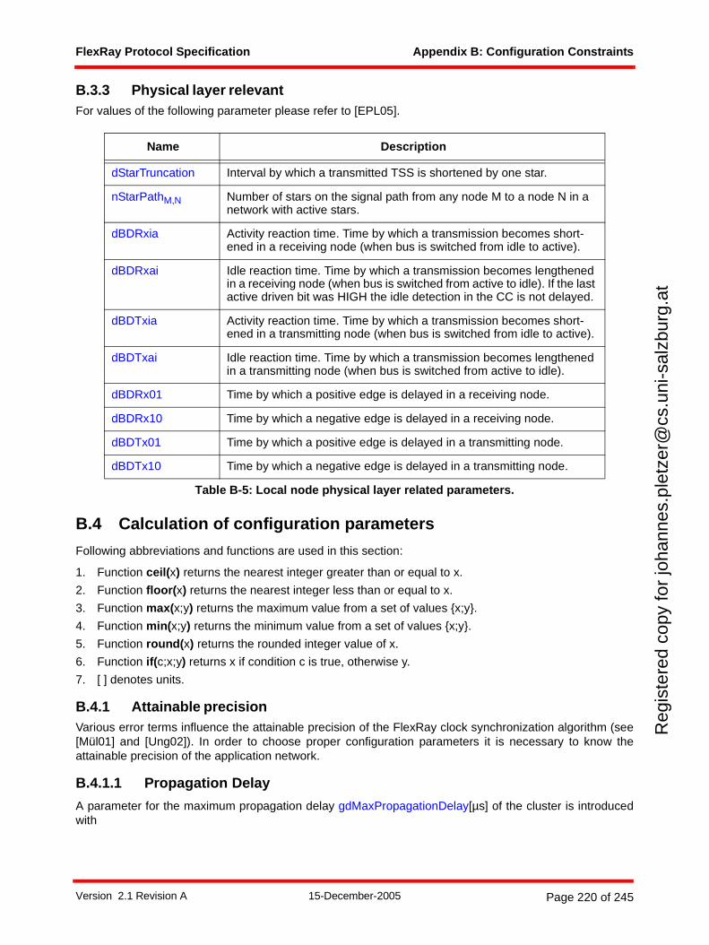
FlexRay Protocol Specification Appendix B: Configuration Constraints
Reg
iste
red
copy
for
joha
nnes
.ple
tzer
@cs
.uni
-sal
zbur
g.at
B.3.3 Physical layer relevantFor values of the following parameter please refer to [EPL05].
B.4 Calculation of configuration parameters
Following abbreviations and functions are used in this section:
1. Function ceil(x) returns the nearest integer greater than or equal to x.
2. Function floor(x) returns the nearest integer less than or equal to x.
3. Function max(x;y) returns the maximum value from a set of values {x;y}.
4. Function min(x;y) returns the minimum value from a set of values {x;y}.
5. Function round(x) returns the rounded integer value of x.
6. Function if(c;x;y) returns x if condition c is true, otherwise y.
7. [ ] denotes units.
B.4.1 Attainable precisionVarious error terms influence the attainable precision of the FlexRay clock synchronization algorithm (see[Mül01] and [Ung02]). In order to choose proper configuration parameters it is necessary to know theattainable precision of the application network.
B.4.1.1 Propagation Delay
A parameter for the maximum propagation delay gdMaxPropagationDelay[µs] of the cluster is introducedwith
Name Description
dStarTruncation Interval by which a transmitted TSS is shortened by one star.
nStarPathM,N Number of stars on the signal path from any node M to a node N in a network with active stars.
dBDRxia Activity reaction time. Time by which a transmission becomes short-ened in a receiving node (when bus is switched from idle to active).
dBDRxai Idle reaction time. Time by which a transmission becomes lengthened in a receiving node (when bus is switched from active to idle). If the last active driven bit was HIGH the idle detection in the CC is not delayed.
dBDTxia Activity reaction time. Time by which a transmission becomes short-ened in a transmitting node (when bus is switched from idle to active).
dBDTxai Idle reaction time. Time by which a transmission becomes lengthened in a transmitting node (when bus is switched from active to idle).
dBDRx01 Time by which a positive edge is delayed in a receiving node.
dBDRx10 Time by which a negative edge is delayed in a receiving node.
dBDTx01 Time by which a positive edge is delayed in a transmitting node.
dBDTx10 Time by which a negative edge is delayed in a transmitting node.
Table B-5: Local node physical layer related parameters.
Version 2.1 Revision A 15-December-2005 Page 220 of 245
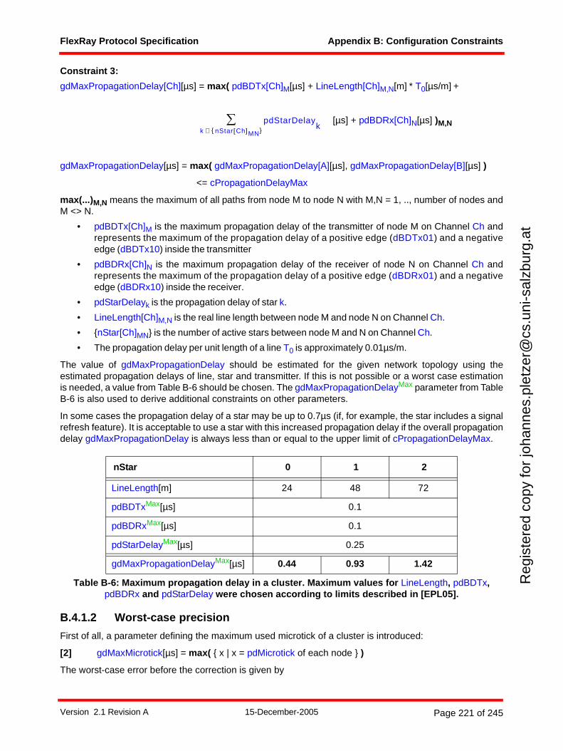
FlexRay Protocol Specification Appendix B: Configuration Constraints
Reg
iste
red
copy
for
joha
nnes
.ple
tzer
@cs
.uni
-sal
zbur
g.at
Constraint 3:
gdMaxPropagationDelay[Ch][µs] = max( pdBDTx[Ch]M[µs] + LineLength[Ch]M,N[m] * T0[µs/m] +
[µs] + pdBDRx[Ch]N[µs] )M,N
gdMaxPropagationDelay[µs] = max( gdMaxPropagationDelay[A][µs], gdMaxPropagationDelay[B][µs] )
<= cPropagationDelayMax
max(...)M,N means the maximum of all paths from node M to node N with M,N = 1, .., number of nodes andM <> N.
• pdBDTx[Ch]M is the maximum propagation delay of the transmitter of node M on Channel Ch andrepresents the maximum of the propagation delay of a positive edge (dBDTx01) and a negativeedge (dBDTx10) inside the transmitter
• pdBDRx[Ch]N is the maximum propagation delay of the receiver of node N on Channel Ch andrepresents the maximum of the propagation delay of a positive edge (dBDRx01) and a negativeedge (dBDRx10) inside the receiver.
• pdStarDelayk is the propagation delay of star k.
• LineLength[Ch]M,N is the real line length between node M and node N on Channel Ch.
• {nStar[Ch]MN} is the number of active stars between node M and N on Channel Ch.
• The propagation delay per unit length of a line T0 is approximately 0.01µs/m.
The value of gdMaxPropagationDelay should be estimated for the given network topology using theestimated propagation delays of line, star and transmitter. If this is not possible or a worst case estimationis needed, a value from Table B-6 should be chosen. The gdMaxPropagationDelayMax parameter from TableB-6 is also used to derive additional constraints on other parameters.
In some cases the propagation delay of a star may be up to 0.7µs (if, for example, the star includes a signalrefresh feature). It is acceptable to use a star with this increased propagation delay if the overall propagationdelay gdMaxPropagationDelay is always less than or equal to the upper limit of cPropagationDelayMax.
B.4.1.2 Worst-case precision
First of all, a parameter defining the maximum used microtick of a cluster is introduced:
[2] gdMaxMicrotick[µs] = max( { x | x = pdMicrotick of each node } )
The worst-case error before the correction is given by
nStar 0 1 2
LineLength[m] 24 48 72
pdBDTxMax[µs] 0.1
pdBDRxMax[µs] 0.1
pdStarDelayMax[µs] 0.25
gdMaxPropagationDelayMax[µs] 0.44 0.93 1.42
Table B-6: Maximum propagation delay in a cluster. Maximum values for LineLength, pdBDTx, pdBDRx and pdStarDelay were chosen according to limits described in [EPL05].
pdStarDelayk
k nStar Ch[ ] MN{ }∈∑
Version 2.1 Revision A 15-December-2005 Page 221 of 245
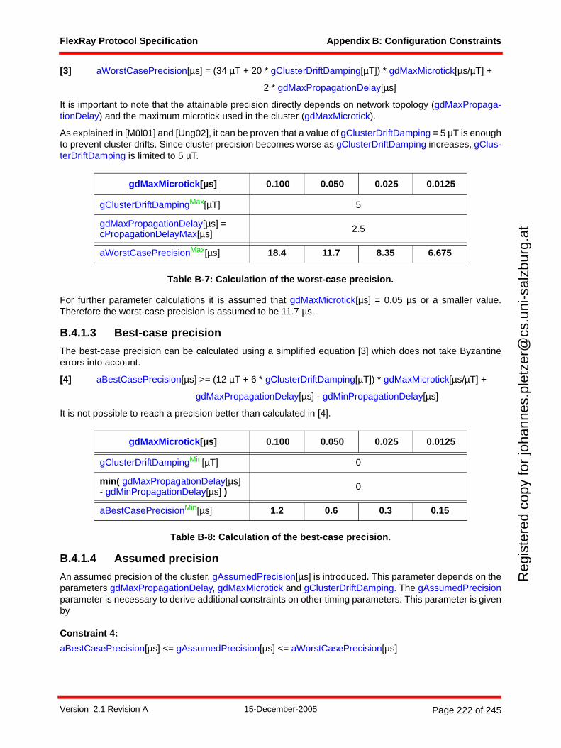
FlexRay Protocol Specification Appendix B: Configuration Constraints
Reg
iste
red
copy
for
joha
nnes
.ple
tzer
@cs
.uni
-sal
zbur
g.at
[3] aWorstCasePrecision[µs] = (34 µT + 20 * gClusterDriftDamping[µT]) * gdMaxMicrotick[µs/µT] +
2 * gdMaxPropagationDelay[µs]
It is important to note that the attainable precision directly depends on network topology (gdMaxPropaga-tionDelay) and the maximum microtick used in the cluster (gdMaxMicrotick).
As explained in [Mül01] and [Ung02], it can be proven that a value of gClusterDriftDamping = 5 µT is enoughto prevent cluster drifts. Since cluster precision becomes worse as gClusterDriftDamping increases, gClus-terDriftDamping is limited to 5 µT.
Table B-7: Calculation of the worst-case precision.
For further parameter calculations it is assumed that gdMaxMicrotick[µs] = 0.05 µs or a smaller value.Therefore the worst-case precision is assumed to be 11.7 µs.
B.4.1.3 Best-case precision
The best-case precision can be calculated using a simplified equation [3] which does not take Byzantineerrors into account.
[4] aBestCasePrecision[µs] >= (12 µT + 6 * gClusterDriftDamping[µT]) * gdMaxMicrotick[µs/µT] +
gdMaxPropagationDelay[µs] - gdMinPropagationDelay[µs]
It is not possible to reach a precision better than calculated in [4].
Table B-8: Calculation of the best-case precision.
B.4.1.4 Assumed precision
An assumed precision of the cluster, gAssumedPrecision[µs] is introduced. This parameter depends on theparameters gdMaxPropagationDelay, gdMaxMicrotick and gClusterDriftDamping. The gAssumedPrecisionparameter is necessary to derive additional constraints on other timing parameters. This parameter is givenby
Constraint 4:
aBestCasePrecision[µs] <= gAssumedPrecision[µs] <= aWorstCasePrecision[µs]
gdMaxMicrotick[µs] 0.100 0.050 0.025 0.0125
gClusterDriftDampingMax[µT] 5
gdMaxPropagationDelay[µs] = cPropagationDelayMax[µs] 2.5
aWorstCasePrecisionMax[µs] 18.4 11.7 8.35 6.675
gdMaxMicrotick[µs] 0.100 0.050 0.025 0.0125
gClusterDriftDampingMin[µT] 0
min( gdMaxPropagationDelay[µs] - gdMinPropagationDelay[µs] ) 0
aBestCasePrecisionMin[µs] 1.2 0.6 0.3 0.15
Version 2.1 Revision A 15-December-2005 Page 222 of 245
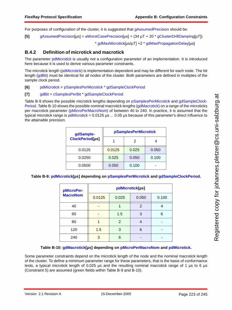
FlexRay Protocol Specification Appendix B: Configuration Constraints
Reg
iste
red
copy
for
joha
nnes
.ple
tzer
@cs
.uni
-sal
zbur
g.at
For purposes of configuration of the cluster, it is suggested that gAssumedPrecision should be:
[5] gAssumedPrecision[µs] = aWorstCasePrecision[µs] = (34 µT + 20 * gClusterDriftDamping[µT])
* gdMaxMicrotick[µs/µT] +2 * gdMaxPropagationDelay[µs]
B.4.2 Definition of microtick and macrotickThe parameter pdMicrotick is usually not a configuration parameter of an implementation. It is introducedhere because it is used to derive various parameter constraints.
The microtick length (pdMicrotick) is implementation dependent and may be different for each node. The bitlength (gdBit) must be identical for all nodes of the cluster. Both parameters are defined in multiples of thesample clock period.
[6] pdMicrotick = pSamplesPerMicrotick * gdSampleClockPeriod
[7] gdBit = cSamplesPerBit * gdSampleClockPeriod
Table B-9 shows the possible microtick lengths depending on pSamplesPerMicrotick and gdSampleClock-Period. Table B-10 shows the possible nominal macrotick lengths (gdMacrotick) on a range of the microticksper macrotick parameter (pMicroPerMacroNom) of between 40 to 240. In practice, it is assumed that thetypical microtick range is pdMicrotick = 0.0125 µs ... 0.05 µs because of this parameter's direct influence tothe attainable precision.
Table B-9: pdMicrotick[µs] depending on pSamplesPerMicrotick and gdSampleClockPeriod.
Table B-10: gdMacrotick[µs] depending on pMicroPerMacroNom and pdMicrotick.
Some parameter constraints depend on the microtick length of the node and the nominal macrotick lengthof the cluster. To define a minimum parameter range for these parameters, that is the basis of conformancetests, a typical microtick length of 0.025 µs and the resulting nominal macrotick range of 1 µs to 6 µs(Constraint 5) are assumed (green fields within Table B-9 and B-10).
gdSample-ClockPeriod[µs]
pSamplesPerMicrotick
1 2 4
0.0125 0.0125 0.025 0.050
0.0250 0.025 0.050 0.100
0.0500 0.050 0.100 -
pMicroPer-MacroNom
pdMicrotick[µs]
0.0125 0.025 0.050 0.100
40 - 1 2 4
60 - 1.5 3 6
80 1 2 4 -
120 1.5 3 6 -
240 3 6 - -
Version 2.1 Revision A 15-December-2005 Page 223 of 245
FlexRay Protocol Specification Appendix B: Configuration Constraints
Reg
iste
red
copy
for
joha
nnes
.ple
tzer
@cs
.uni
-sal
zbur
g.at
The desired nominal macrotick length gdMacrotick in µs can be chosen to be less than, greater than, orequal to the assumed precision. In all cases the macrotick length must fulfill the following constraint:
Constraint 5:
cdMinMTNom[µs] <= gdMacrotick[µs] <= cdMaxMTNom[µs]
Depending on the desired macrotick length the following additional constraint must be met.
Constraint 6:
gdMacrotick[µs] >= cMicroPerMacroNomMin[µT] * pdMicrotick[µs/µT]
The macrotick, expressed in microticks, is given by
[8] pMicroPerMacroNom[µT/MT]= gdMacrotick[µs/MT] / pdMicrotick[µs/µT]
= pMicroPerCycle[µT] / gMacroPerCycle[MT]
Note that pMicroPerMacroNom may have a fractional part (i.e., it does not need to be an integral numberof microticks).
Note that pMicroPerCycle might have rounding errors according to section 8.2.3.
For gdMacrotick exists an additional constraint because of the startup procedure and pMicroInitialOffset:
Constraint 7:
gdMacrotick[µs] <= aFrameLengthStatic[gdBit] * gdBitMin[µs/gdBit]
However, the fulfillment of this constraint is given in any case because of the minimum frame length of 80bits, a bit duration of around 100 ns and a maximum macrotick length of 6 µs.
B.4.3 gdMaxInitializationErrorConsider the following assumptions:
• The maximum initialization error that an integrating node may have is
0 µs <= gdMaxInitializationError[µs] <= gAssumedPrecision[µs]
Constraint 8:
gAssumedPrecision[µs] >= gdMaxInitializationError[µs] >=
2 * (gdMaxMicrotick[µs] * (1 + cClockDeviationMax)) + gdMaxPropagationDelay[µs]
The upper limit is given by
gdMaxInitializationError[µs] = gAssumedPrecision[µs] = aWorstCasePrecision[µs] = 11.7µs.
B.4.4 pdAcceptedStartupRangeConsider the following assumptions:
• During integration a clock synchronization error greater than the assumed precision may occur andbe acceptable.
Constraint 9:
pdAcceptedStartupRange[µT] >= ceil( (gAssumedPrecision[µs] + gdMaxInitializationError[µs]) /
(pdMicrotick[µs/µT] * (1 - cClockDeviationMax)) )
The maximum value of this expression occurs when
• gAssumedPrecision = aWorstCasePrecision,
Version 2.1 Revision A 15-December-2005 Page 224 of 245
FlexRay Protocol Specification Appendix B: Configuration Constraints
Reg
iste
red
copy
for
joha
nnes
.ple
tzer
@cs
.uni
-sal
zbur
g.at
• gdMaxInitializationError = aWorstCasePrecision,
• pdMicrotick = 0.0125 µs
and is
pdAcceptedStartupRange = ceil( 1874.8 ) µT = 1875 µT.
B.4.5 pClusterDriftDampingConsider the following assumptions:
• The drift damping factor gClusterDriftDamping is defined in multiples of the longest microtickgdMaxMicrotick within the cluster:
gClusterDriftDamping[µT] = n * 1 µT with n = 0, 1, 2, ..., 5.
• The maximum microtick of a cluster gdMaxMicrotick is a multiple m of each nodes local microtickpdMicrotick.
gdMaxMicrotick = m * pdMicrotick with m = 1, 2, 4 (see pSamplesPerMicrotick).
• The local drift damping pClusterDriftDamping is calculated by
Constraint 10:
pClusterDriftDamping[µT] <= gdMaxMicrotick[µs] / pdMicrotick[µs] * gClusterDriftDamping[µT]
Constraint 10 should be treated as a recommendation. In practice it is expected that the drift damping factoris chosen such that
pClusterDriftDamping ~ gClusterDriftDamping.
The upper limit of pClusterDriftDamping is given by gdMaxMicrotick/pdMicrotick = 4. Therefore
pClusterDriftDamping = 4 * 5 µT = 20 µT.
B.4.6 gdActionPointOffsetConsider the following assumptions:
• The action point offset should be greater than the assumed precision.
• A minimum propagation delay of the network as seen by the local node is given by gdMinPropaga-tionDelay[µs].
Constraint 11:
gdActionPointOffset[MT] >= ceil( (gAssumedPrecision[µs] - gdMinPropagationDelay[µs]) /
(gdMacrotick[µs/MT] * (1 - cClockDeviationMax)) )
In practice the minimum propagation delay gdMinPropagationDelay may be set to zero.
In order to prevent the possibility of the creation of cliques114 during startup an additional safety margin mustbe added. In this case Constraint 12 replaces Constraint 11.
Constraint 12:
gdActionPointOffset[MT] >= ceil( (2 * gAssumedPrecision[µs] - gdMinPropagationDelay[µs] +
2 * gdMaxInitializationError[µs]) / (gdMacrotick[µs/MT] * (1 - cClockDeviationMax)) )
114 Clique formation may be possible if more than two coldstart nodes are configured in the cluster under specific error scenarios.
Version 2.1 Revision A 15-December-2005 Page 225 of 245
FlexRay Protocol Specification Appendix B: Configuration Constraints
Reg
iste
red
copy
for
joha
nnes
.ple
tzer
@cs
.uni
-sal
zbur
g.at
In order to determine the configuration range of the gdActionPointOffset an additional margin of safety istaken into account. As a result, the parameter gdActionPointOffset must be configurable over a range of 1to 63 MT.115 This also allows a static slot design with additional safety margin, i.e. the action point of thestatic slots includes a safety margin beyond the achievable precision of the cluster.
B.4.7 gdMinislotActionPointOffsetConsider the following assumptions:
• The action point offset should be greater than the attainable precision.
Constraint 13:
gdMinislotActionPointOffset[MT] >= ceil( (gAssumedPrecision[µs] - gdMinPropagationDelay[µs]) /
(gdMacrotick[µs/MT] * (1 - cClockDeviationMax)) )
gdMinislotActionPointOffset shall be configurable in a range of 1 to 31 MT.
gdMinislotActionPointOffset can be independently configured from gdActionPointOffset. This is useful if thestatic segment design includes an additional safety margin that is not required in the dynamic segment.gdMinislotActionPointOffset can also be different from gdActionPointOffset if the worst case precision(causing gdActionPointOffset) can be replaced by an assumed "average precision" for the dynamicsegment. In both cases, the independent choice of gdMinislotActionPointOffset allows increased throughputrespective bandwidth within the dynamic segment.
B.4.8 gdMinislotConsider the following assumptions:
• The minislot action point gdMinislotActionPointOffset is greater than or equal to the assumedprecision gAssumedPrecision.
• The maximum propagation delay gdMaxPropagationDelay of the network is taken into account.
Constraint 14:
gdMinislot[MT] >= gdMinislotActionPointOffset[MT] + ceil( (gdMaxPropagationDelay[µs] +
gAssumedPrecision[µs]) / (gdMacrotick[µs/MT] * (1 - cClockDeviationMax)) )
With the assumptions for gdMinislotActionPointOffset given in section B.4.7 and allowing for a margin ofsafety, the parameter gdMinislot must be configurable over a range of 2 to 63 MT.
Parameter Constraint 11 Constraint 12
gAssumedPrecisionMax[µs] 11.7 11.7
gdMinPropagationDelayMin[µs] 0 0
gdMaxInitializationErrorMax[µs] - 11.7
gdMacrotickMin[µs] 1 1
gdActionPointOffsetMax[MT] 12 47
Table B-11: Calculation of values for gdActionPointOffset.
115 Note that the gdActionPointOffset parameter also specifies the action point in the symbol window.
Version 2.1 Revision A 15-December-2005 Page 226 of 245
FlexRay Protocol Specification Appendix B: Configuration Constraints
Reg
iste
red
copy
for
joha
nnes
.ple
tzer
@cs
.uni
-sal
zbur
g.at
B.4.9 gdStaticSlotConsider the following assumptions:
• A frame must consists of at least gdTSSTransmitter, cdFSS, 80 gdBit header and trailer (with gPay-loadLengthStatic = 0), and cdFES.
• Each payload data word is equal to 2 * (8 gdBit + cdBSS[gdBit]) = 20 gdBit.
The length of a frame is given by:
[9] aFrameLength[gdBit] = gdTSSTransmitter[gdBit] + cdFSS[gdBit] + 80 gdBit +
aPayloadLength[2-byte-word] * 20 gdBit + cdFES[gdBit]
Substituting the length of a static frame for aPayloadLength results in:
[10] aFrameLengthStatic = aFrameLength with aPayloadLength = gPayloadLengthStatic
Additional to the frame length the following
• The maximum length of a frame is increased depending on the clock quality (cClockDeviationMax)and the minimum duration of a macrotick.
• The influence of the precision is taken into account by gdActionPointOffset.
• An idle detection time of cChannelIdleDelimiter between two consecutive frames is considered.
• The maximum propagation delay gdMaxPropagationDelay of the cluster must also be taken intoaccount.
Using equation [9] and [10] the minimum static slot length for systems can be calculated by Constraint 15:
Constraint 15:
gdStaticSlot[MT] = 2 * gdActionPointOffset[MT] + ceil( ((aFrameLengthStatic[gdBit] +
cChannelIdleDelimiter[gdBit]) * gdBitMax[µs/gdBit] + gdMinPropagationDelay[µs] +
gdMaxPropagationDelay[µs]) / (gdMacrotick[µs/MT] * (1 - cClockDeviationMax)) )
Bit Rate [MBit/s] 2.5 5 10
gdActionPointOffsetMin[MT] 1
gdActionPointOffsetMax[MT] 63
gdTSSTransmitter Min[gdBit] 3 4 6
gdTSSTransmitterMax[gdBit] 5 8 15
aFrameLengthStaticMin[gdBit] 86 87 89
aFrameLengthStaticMax[gdBit] 2628 2631 2638
gdBitMax[µs] 0.4006 0.2003 0.10015
gdMinPropagationDelayMin[µs] 0
gdMinPropagationDelayMax[µs] 2.5
gdMaxPropagationDelayMin[µs] 0
gdMaxPropagationDelayMax[µs] 2.5
Table B-12: Calculation of minimum and maximum values for gdStaticSlot.
Version 2.1 Revision A 15-December-2005 Page 227 of 245
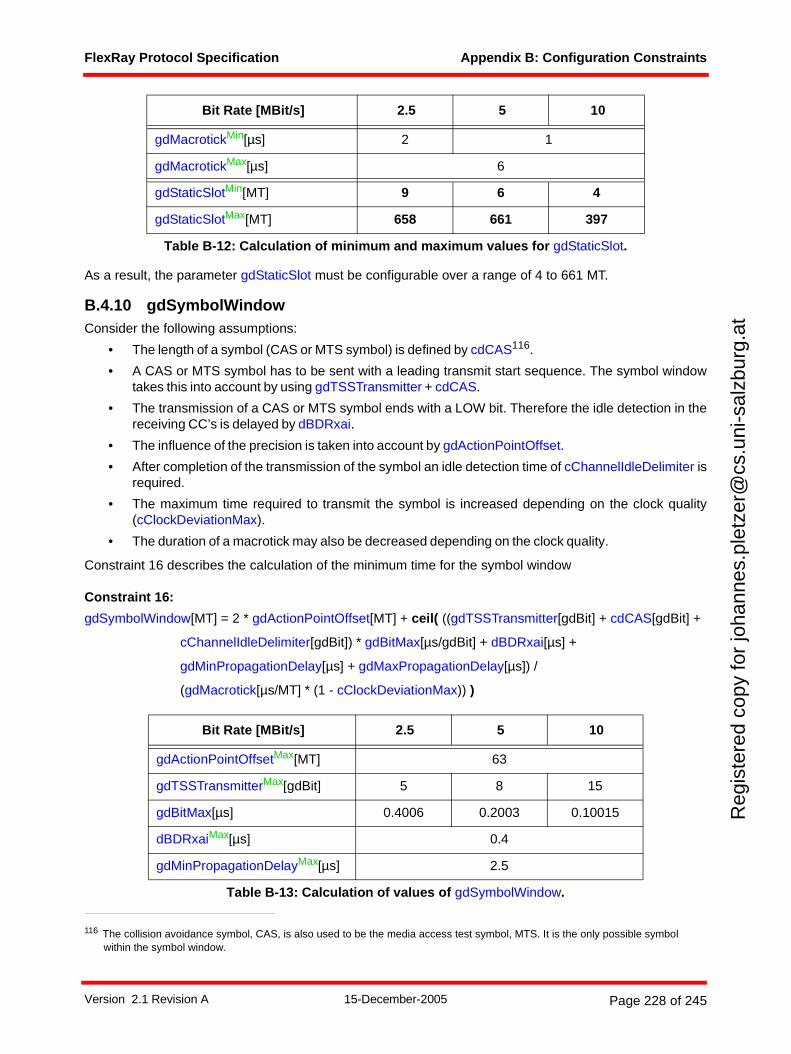
FlexRay Protocol Specification Appendix B: Configuration Constraints
Reg
iste
red
copy
for
joha
nnes
.ple
tzer
@cs
.uni
-sal
zbur
g.at
As a result, the parameter gdStaticSlot must be configurable over a range of 4 to 661 MT.
B.4.10 gdSymbolWindowConsider the following assumptions:
• The length of a symbol (CAS or MTS symbol) is defined by cdCAS116.
• A CAS or MTS symbol has to be sent with a leading transmit start sequence. The symbol windowtakes this into account by using gdTSSTransmitter + cdCAS.
• The transmission of a CAS or MTS symbol ends with a LOW bit. Therefore the idle detection in thereceiving CC’s is delayed by dBDRxai.
• The influence of the precision is taken into account by gdActionPointOffset.
• After completion of the transmission of the symbol an idle detection time of cChannelIdleDelimiter isrequired.
• The maximum time required to transmit the symbol is increased depending on the clock quality(cClockDeviationMax).
• The duration of a macrotick may also be decreased depending on the clock quality.
Constraint 16 describes the calculation of the minimum time for the symbol window
Constraint 16:
gdSymbolWindow[MT] = 2 * gdActionPointOffset[MT] + ceil( ((gdTSSTransmitter[gdBit] + cdCAS[gdBit] +
cChannelIdleDelimiter[gdBit]) * gdBitMax[µs/gdBit] + dBDRxai[µs] +
gdMinPropagationDelay[µs] + gdMaxPropagationDelay[µs]) /
(gdMacrotick[µs/MT] * (1 - cClockDeviationMax)) )
gdMacrotickMin[µs] 2 1
gdMacrotickMax[µs] 6
gdStaticSlotMin[MT] 9 6 4
gdStaticSlotMax[MT] 658 661 397
116 The collision avoidance symbol, CAS, is also used to be the media access test symbol, MTS. It is the only possible symbol within the symbol window.
Bit Rate [MBit/s] 2.5 5 10
gdActionPointOffsetMax[MT] 63
gdTSSTransmitterMax[gdBit] 5 8 15
gdBitMax[µs] 0.4006 0.2003 0.10015
dBDRxaiMax[µs] 0.4
gdMinPropagationDelayMax[µs] 2.5
Table B-13: Calculation of values of gdSymbolWindow.
Bit Rate [MBit/s] 2.5 5 10
Table B-12: Calculation of minimum and maximum values for gdStaticSlot.
Version 2.1 Revision A 15-December-2005 Page 228 of 245
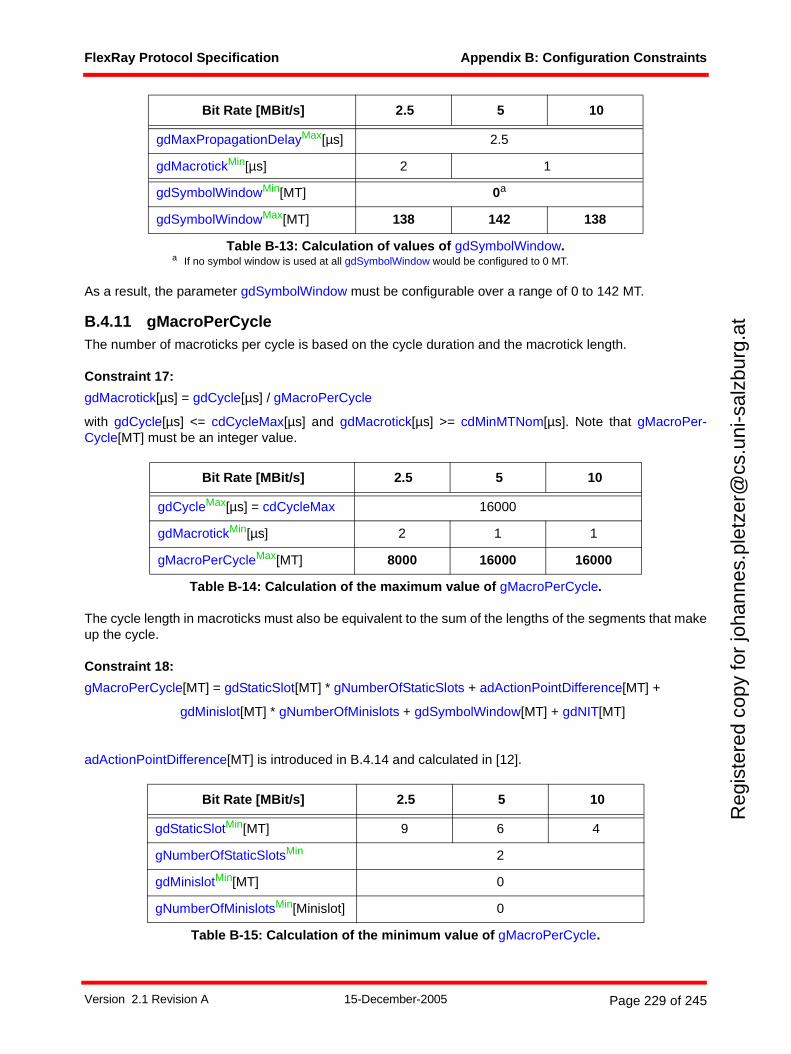
FlexRay Protocol Specification Appendix B: Configuration Constraints
Reg
iste
red
copy
for
joha
nnes
.ple
tzer
@cs
.uni
-sal
zbur
g.at
As a result, the parameter gdSymbolWindow must be configurable over a range of 0 to 142 MT.
B.4.11 gMacroPerCycleThe number of macroticks per cycle is based on the cycle duration and the macrotick length.
Constraint 17:
gdMacrotick[µs] = gdCycle[µs] / gMacroPerCycle
with gdCycle[µs] <= cdCycleMax[µs] and gdMacrotick[µs] >= cdMinMTNom[µs]. Note that gMacroPer-Cycle[MT] must be an integer value.
The cycle length in macroticks must also be equivalent to the sum of the lengths of the segments that makeup the cycle.
Constraint 18:
gMacroPerCycle[MT] = gdStaticSlot[MT] * gNumberOfStaticSlots + adActionPointDifference[MT] +
gdMinislot[MT] * gNumberOfMinislots + gdSymbolWindow[MT] + gdNIT[MT]
adActionPointDifference[MT] is introduced in B.4.14 and calculated in [12].
gdMaxPropagationDelayMax[µs] 2.5
gdMacrotickMin[µs] 2 1
gdSymbolWindowMin[MT] 0a
gdSymbolWindowMax[MT] 138 142 138
a If no symbol window is used at all gdSymbolWindow would be configured to 0 MT.
Bit Rate [MBit/s] 2.5 5 10
gdCycleMax[µs] = cdCycleMax 16000
gdMacrotickMin[µs] 2 1 1
gMacroPerCycleMax[MT] 8000 16000 16000
Table B-14: Calculation of the maximum value of gMacroPerCycle.
Bit Rate [MBit/s] 2.5 5 10
gdStaticSlotMin[MT] 9 6 4
gNumberOfStaticSlotsMin 2
gdMinislotMin[MT] 0
gNumberOfMinislotsMin[Minislot] 0
Table B-15: Calculation of the minimum value of gMacroPerCycle.
Bit Rate [MBit/s] 2.5 5 10
Table B-13: Calculation of values of gdSymbolWindow.
Version 2.1 Revision A 15-December-2005 Page 229 of 245
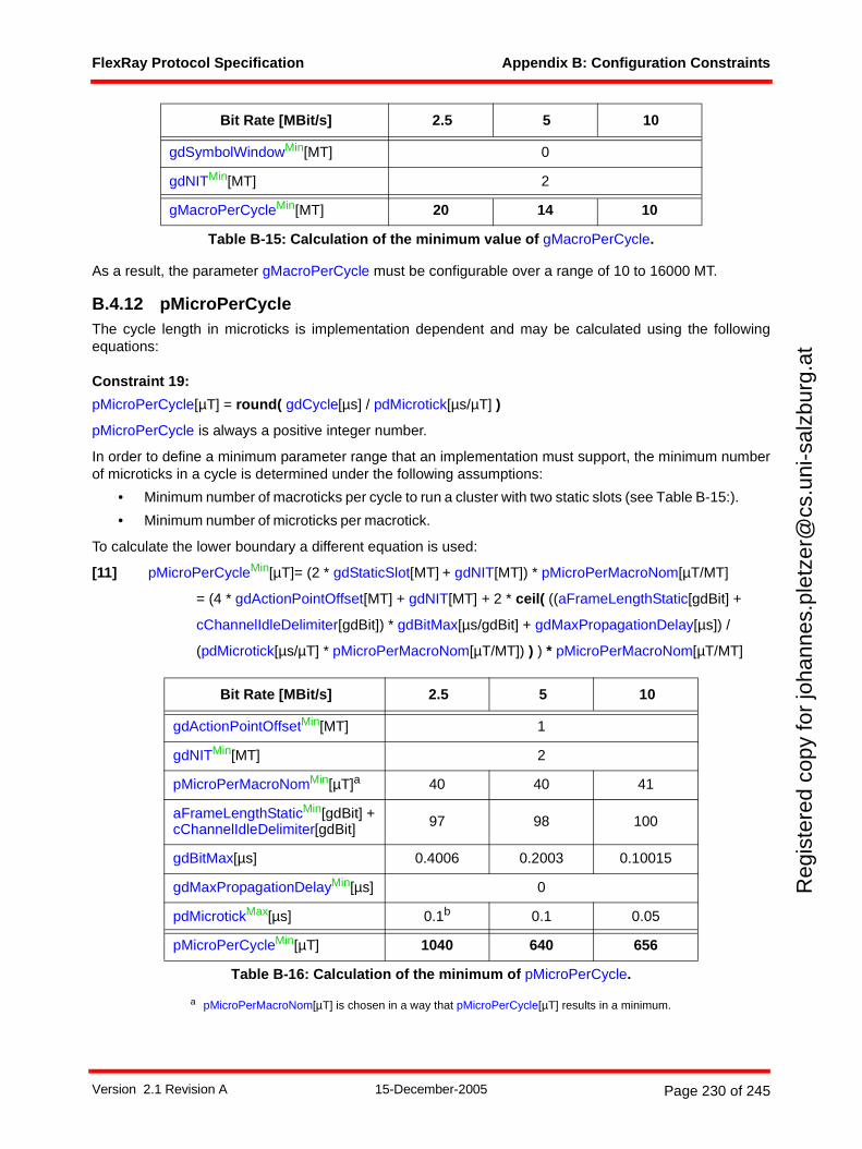
FlexRay Protocol Specification Appendix B: Configuration Constraints
Reg
iste
red
copy
for
joha
nnes
.ple
tzer
@cs
.uni
-sal
zbur
g.at
As a result, the parameter gMacroPerCycle must be configurable over a range of 10 to 16000 MT.
B.4.12 pMicroPerCycleThe cycle length in microticks is implementation dependent and may be calculated using the followingequations:
Constraint 19:
pMicroPerCycle[µT] = round( gdCycle[µs] / pdMicrotick[µs/µT] )
pMicroPerCycle is always a positive integer number.
In order to define a minimum parameter range that an implementation must support, the minimum numberof microticks in a cycle is determined under the following assumptions:
• Minimum number of macroticks per cycle to run a cluster with two static slots (see Table B-15:).
• Minimum number of microticks per macrotick.
To calculate the lower boundary a different equation is used:
[11] pMicroPerCycleMin[µT]= (2 * gdStaticSlot[MT] + gdNIT[MT]) * pMicroPerMacroNom[µT/MT]
= (4 * gdActionPointOffset[MT] + gdNIT[MT] + 2 * ceil( ((aFrameLengthStatic[gdBit] +
cChannelIdleDelimiter[gdBit]) * gdBitMax[µs/gdBit] + gdMaxPropagationDelay[µs]) /
(pdMicrotick[µs/µT] * pMicroPerMacroNom[µT/MT]) ) ) * pMicroPerMacroNom[µT/MT]
gdSymbolWindowMin[MT] 0
gdNITMin[MT] 2
gMacroPerCycleMin[MT] 20 14 10
Bit Rate [MBit/s] 2.5 5 10
gdActionPointOffsetMin[MT] 1
gdNITMin[MT] 2
pMicroPerMacroNomMin[µT]a
a pMicroPerMacroNom[µT] is chosen in a way that pMicroPerCycle[µT] results in a minimum.
40 40 41
aFrameLengthStaticMin[gdBit] +cChannelIdleDelimiter[gdBit] 97 98 100
gdBitMax[µs] 0.4006 0.2003 0.10015
gdMaxPropagationDelayMin[µs] 0
pdMicrotickMax[µs] 0.1b 0.1 0.05
pMicroPerCycleMin[µT] 1040 640 656
Table B-16: Calculation of the minimum of pMicroPerCycle.
Bit Rate [MBit/s] 2.5 5 10
Table B-15: Calculation of the minimum value of gMacroPerCycle.
Version 2.1 Revision A 15-December-2005 Page 230 of 245

FlexRay Protocol Specification Appendix B: Configuration Constraints
Reg
iste
red
copy
for
joha
nnes
.ple
tzer
@cs
.uni
-sal
zbur
g.at
The maximum number of microticks per cycle depends on the microtick length. It is not required that anyimplementation supports any microtick length but for each supported bit rate at least one microtick lengthand the related number of microticks per cycle must be supported (see Table B-16). To support the minimummacrotick length of 1 µs the bold marked numbers of microtick per cycle should be supported.
As a result, the parameter pMicroPerCycle must be configurable at least over a range of 640 to 640000 µT.
B.4.13 gdDynamicSlotIdlePhaseConsider the following assumptions:
• The duration of gdDynamicSlotIdlePhase[Minislots] must be greater than or equal to the idledetection time.
• The idle detection time must be calculated based on the uncorrected bit time and therefore equalscChannelIdleDelimiter * gdBitMax.
• The macroticks may also be shortened by the clock deviation.
Constraint 20:
gdDynamicSlotIdlePhase[Minislot] >= ceil( ( ceil( (cChannelIdleDelimiter * gdBitMax[µs] +
gAssumedPrecision[µs] + gdMaxPropagationDelay[µs]) /
(gdMacrotick[µs/MT] * (1 - cClockDeviationMax)) ) - (gdMinislot[MT] -
gdMinislotActionPointOffset[MT]) ) / gdMinislot[MT/Minislot] )
Note, to calculate the minimum and the maximum value of gdDynamicSlotIdlePhase the Constraint 14 mustalso be fulfilled.
b With pMicroPerMacroNomMin = 40 µT and pdMicrotick = 0.2 µs the maximum length of gdMacrotick would exceed the maximum macrotick length of 6 µs.
Bit Rate [MBit/s] 2.5 5 10
gdCycleMax[µs] = cdCycleMax 16000
pdMicrotick[µs]0.0500.100
-
0.0250.0500.100
0.01250.0250.050
pMicroPerCycleMax[µT] with pdMicrotick = 0.100 µs 160000 160000 -
pMicroPerCycleMax[µT] with pdMicrotick = 0.050 µs 320000 320000 320000
pMicroPerCycleMax[µT] with pdMicrotick = 0.025 µs - 640000 640000
pMicroPerCycleMax[µT] with pdMicrotick = 0.0125 µs - - 1280000
Table B-17: Calculation of the maximum of pMicroPerCycle.
Bit Rate [MBit/s] 2.5 5 10
gdBitMax[µs] 0.4006 0.2003 0.10015
Table B-18: Calculation of the minimum and maximum of gdDynamicSlotIdlePhase.
Version 2.1 Revision A 15-December-2005 Page 231 of 245
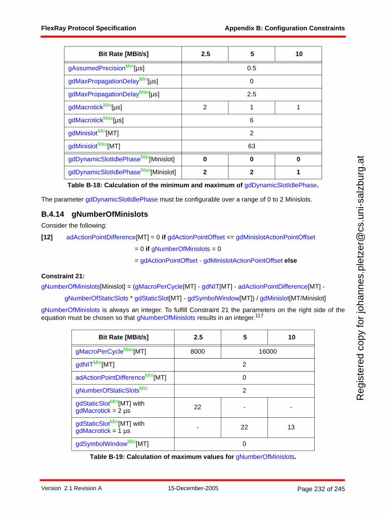
FlexRay Protocol Specification Appendix B: Configuration Constraints
Reg
iste
red
copy
for
joha
nnes
.ple
tzer
@cs
.uni
-sal
zbur
g.at
The parameter gdDynamicSlotIdlePhase must be configurable over a range of 0 to 2 Minislots.
B.4.14 gNumberOfMinislotsConsider the following:
[12] adActionPointDifference[MT] = 0 if gdActionPointOffset <= gdMinislotActionPointOffset
= 0 if gNumberOfMinislots = 0
= gdActionPointOffset - gdMinislotActionPointOffset else
Constraint 21:
gNumberOfMinislots[Minislot] = (gMacroPerCycle[MT] - gdNIT[MT] - adActionPointDifference[MT] -
gNumberOfStaticSlots * gdStaticSlot[MT] - gdSymbolWindow[MT]) / gdMinislot[MT/Minislot]
gNumberOfMinislots is always an integer. To fulfill Constraint 21 the parameters on the right side of theequation must be chosen so that gNumberOfMinislots results in an integer.117
gAssumedPrecisionMin[µs] 0.5
gdMaxPropagationDelayMin[µs] 0
gdMaxPropagationDelayMax[µs] 2.5
gdMacrotickMin[µs] 2 1 1
gdMacrotickMax[µs] 6
gdMinislotMin[MT] 2
gdMinislotMax[MT] 63
gdDynamicSlotIdlePhaseMin[Minislot] 0 0 0
gdDynamicSlotIdlePhaseMax[Minislot] 2 2 1
Bit Rate [MBit/s] 2.5 5 10
gMacroPerCycleMax[MT] 8000 16000
gdNITMin[MT] 2
adActionPointDifferenceMin[MT] 0
gNumberOfStaticSlotsMin 2
gdStaticSlotMin[MT] with gdMacrotick = 2 µs 22 - -
gdStaticSlotMin[MT] with gdMacrotick = 1 µs - 22 13
gdSymbolWindowMin[MT] 0
Table B-19: Calculation of maximum values for gNumberOfMinislots.
Bit Rate [MBit/s] 2.5 5 10
Table B-18: Calculation of the minimum and maximum of gdDynamicSlotIdlePhase.
Version 2.1 Revision A 15-December-2005 Page 232 of 245
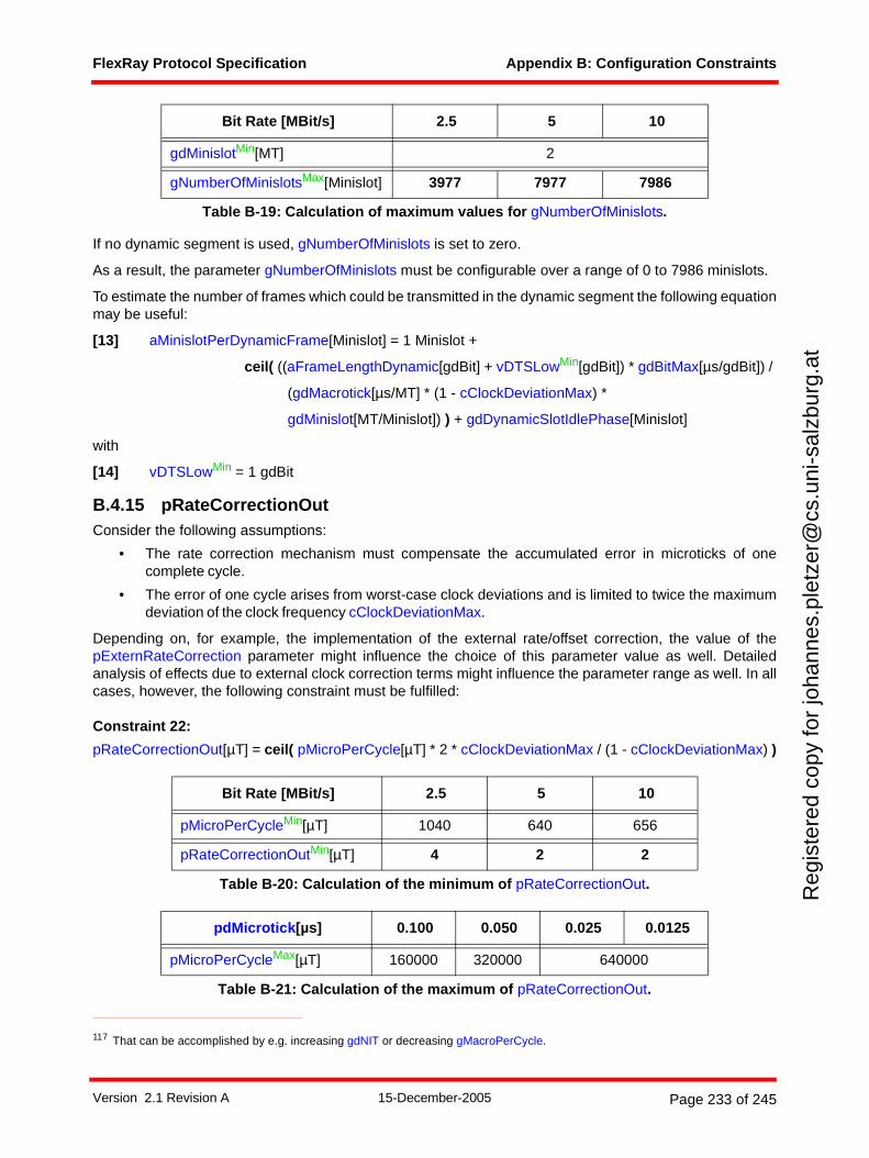
FlexRay Protocol Specification Appendix B: Configuration Constraints
Reg
iste
red
copy
for
joha
nnes
.ple
tzer
@cs
.uni
-sal
zbur
g.at
If no dynamic segment is used, gNumberOfMinislots is set to zero.
As a result, the parameter gNumberOfMinislots must be configurable over a range of 0 to 7986 minislots.
To estimate the number of frames which could be transmitted in the dynamic segment the following equationmay be useful:
[13] aMinislotPerDynamicFrame[Minislot] = 1 Minislot +
ceil( ((aFrameLengthDynamic[gdBit] + vDTSLowMin[gdBit]) * gdBitMax[µs/gdBit]) /
(gdMacrotick[µs/MT] * (1 - cClockDeviationMax) *
gdMinislot[MT/Minislot]) ) + gdDynamicSlotIdlePhase[Minislot]
with
[14] vDTSLowMin = 1 gdBit
B.4.15 pRateCorrectionOutConsider the following assumptions:
• The rate correction mechanism must compensate the accumulated error in microticks of onecomplete cycle.
• The error of one cycle arises from worst-case clock deviations and is limited to twice the maximumdeviation of the clock frequency cClockDeviationMax.
Depending on, for example, the implementation of the external rate/offset correction, the value of thepExternRateCorrection parameter might influence the choice of this parameter value as well. Detailedanalysis of effects due to external clock correction terms might influence the parameter range as well. In allcases, however, the following constraint must be fulfilled:
Constraint 22:
pRateCorrectionOut[µT] = ceil( pMicroPerCycle[µT] * 2 * cClockDeviationMax / (1 - cClockDeviationMax) )
117 That can be accomplished by e.g. increasing gdNIT or decreasing gMacroPerCycle.
gdMinislotMin[MT] 2
gNumberOfMinislotsMax[Minislot] 3977 7977 7986
Bit Rate [MBit/s] 2.5 5 10
pMicroPerCycleMin[µT] 1040 640 656
pRateCorrectionOutMin[µT] 4 2 2
Table B-20: Calculation of the minimum of pRateCorrectionOut.
pdMicrotick[µs] 0.100 0.050 0.025 0.0125
pMicroPerCycleMax[µT] 160000 320000 640000
Table B-21: Calculation of the maximum of pRateCorrectionOut.
Bit Rate [MBit/s] 2.5 5 10
Table B-19: Calculation of maximum values for gNumberOfMinislots.
Version 2.1 Revision A 15-December-2005 Page 233 of 245
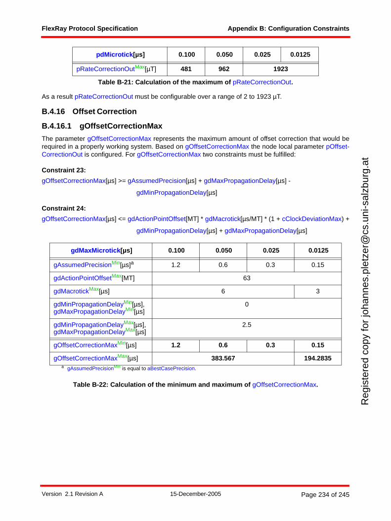
FlexRay Protocol Specification Appendix B: Configuration Constraints
Reg
iste
red
copy
for
joha
nnes
.ple
tzer
@cs
.uni
-sal
zbur
g.at
As a result pRateCorrectionOut must be configurable over a range of 2 to 1923 µT.
B.4.16 Offset Correction
B.4.16.1 gOffsetCorrectionMax
The parameter gOffsetCorrectionMax represents the maximum amount of offset correction that would berequired in a properly working system. Based on gOffsetCorrectionMax the node local parameter pOffset-CorrectionOut is configured. For gOffsetCorrectionMax two constraints must be fulfilled:
Constraint 23:
gOffsetCorrectionMax[µs] >= gAssumedPrecision[µs] + gdMaxPropagationDelay[µs] -
gdMinPropagationDelay[µs]
Constraint 24:
gOffsetCorrectionMax[µs] <= gdActionPointOffset[MT] * gdMacrotick[µs/MT] * (1 + cClockDeviationMax) +
gdMinPropagationDelay[µs] + gdMaxPropagationDelay[µs]
Table B-22: Calculation of the minimum and maximum of gOffsetCorrectionMax.
pRateCorrectionOutMax[µT] 481 962 1923
gdMaxMicrotick[µs] 0.100 0.050 0.025 0.0125
gAssumedPrecisionMin[µs]a
a gAssumedPrecisionMin is equal to aBestCasePrecision.
1.2 0.6 0.3 0.15
gdActionPointOffsetMax[MT] 63
gdMacrotickMax[µs] 6 3
gdMinPropagationDelayMin[µs],gdMaxPropagationDelayMin[µs]
0
gdMinPropagationDelayMax[µs],gdMaxPropagationDelayMax[µs]
2.5
gOffsetCorrectionMaxMin[µs] 1.2 0.6 0.3 0.15
gOffsetCorrectionMaxMax[µs] 383.567 194.2835
pdMicrotick[µs] 0.100 0.050 0.025 0.0125
Table B-21: Calculation of the maximum of pRateCorrectionOut.
Version 2.1 Revision A 15-December-2005 Page 234 of 245
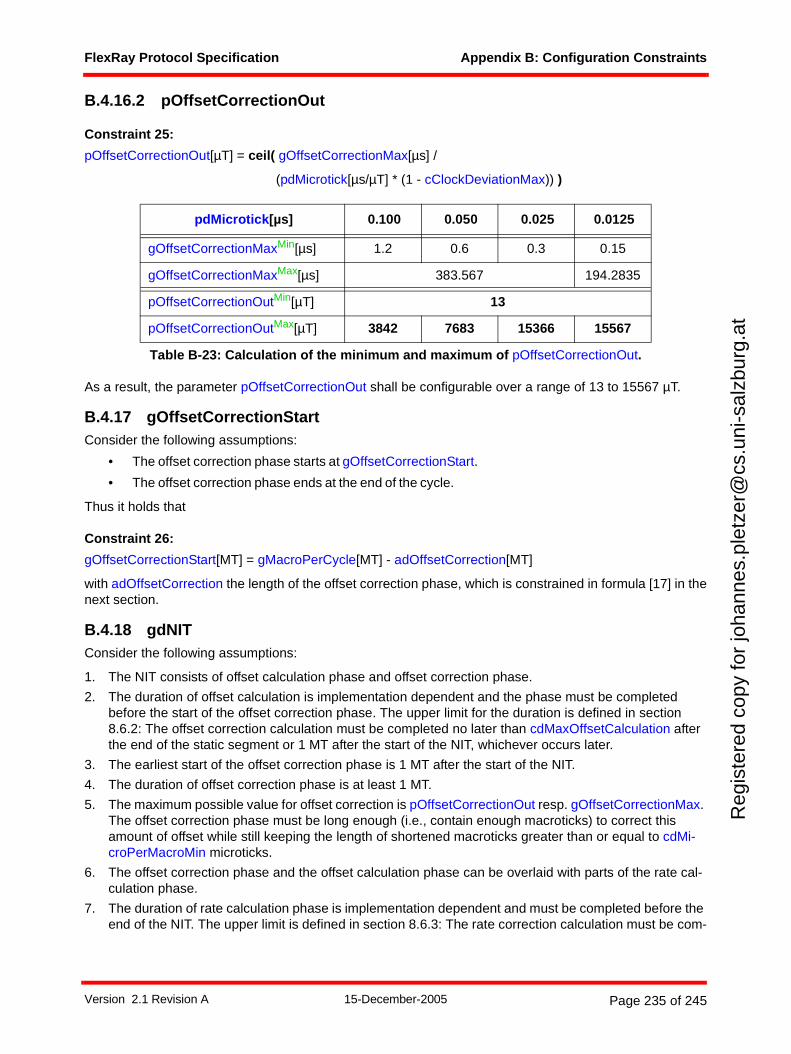
FlexRay Protocol Specification Appendix B: Configuration Constraints
Reg
iste
red
copy
for
joha
nnes
.ple
tzer
@cs
.uni
-sal
zbur
g.at
B.4.16.2 pOffsetCorrectionOut
Constraint 25:
pOffsetCorrectionOut[µT] = ceil( gOffsetCorrectionMax[µs] /
(pdMicrotick[µs/µT] * (1 - cClockDeviationMax)) )
As a result, the parameter pOffsetCorrectionOut shall be configurable over a range of 13 to 15567 µT.
B.4.17 gOffsetCorrectionStartConsider the following assumptions:
• The offset correction phase starts at gOffsetCorrectionStart.
• The offset correction phase ends at the end of the cycle.
Thus it holds that
Constraint 26:
gOffsetCorrectionStart[MT] = gMacroPerCycle[MT] - adOffsetCorrection[MT]
with adOffsetCorrection the length of the offset correction phase, which is constrained in formula [17] in thenext section.
B.4.18 gdNITConsider the following assumptions:
1. The NIT consists of offset calculation phase and offset correction phase.
2. The duration of offset calculation is implementation dependent and the phase must be completed before the start of the offset correction phase. The upper limit for the duration is defined in section 8.6.2: The offset correction calculation must be completed no later than cdMaxOffsetCalculation after the end of the static segment or 1 MT after the start of the NIT, whichever occurs later.
3. The earliest start of the offset correction phase is 1 MT after the start of the NIT.
4. The duration of offset correction phase is at least 1 MT.
5. The maximum possible value for offset correction is pOffsetCorrectionOut resp. gOffsetCorrectionMax. The offset correction phase must be long enough (i.e., contain enough macroticks) to correct this amount of offset while still keeping the length of shortened macroticks greater than or equal to cdMi-croPerMacroMin microticks.
6. The offset correction phase and the offset calculation phase can be overlaid with parts of the rate cal-culation phase.
7. The duration of rate calculation phase is implementation dependent and must be completed before the end of the NIT. The upper limit is defined in section 8.6.3: The rate correction calculation must be com-
pdMicrotick[µs] 0.100 0.050 0.025 0.0125
gOffsetCorrectionMaxMin[µs] 1.2 0.6 0.3 0.15
gOffsetCorrectionMaxMax[µs] 383.567 194.2835
pOffsetCorrectionOutMin[µT] 13
pOffsetCorrectionOutMax[µT] 3842 7683 15366 15567
Table B-23: Calculation of the minimum and maximum of pOffsetCorrectionOut.
Version 2.1 Revision A 15-December-2005 Page 235 of 245
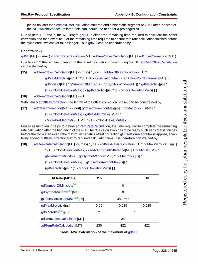
FlexRay Protocol Specification Appendix B: Configuration Constraints
Reg
iste
red
copy
for
joha
nnes
.ple
tzer
@cs
.uni
-sal
zbur
g.at
pleted no later than cdMaxRateCalculation after the end of the static segment or 2 MT after the start of the NIT, whichever occurs later. This can induce the need for a prolonged NIT.
Due to item 1, 6 and 7, the NIT length gdNIT is either the remaining time required to calculate the offsetcorrection and then execute it, or the remaining time required to ensure that rate calculation finishes beforethe cycle ends, whichever takes longer. Thus gdNIT can be constrained by
Constraint 27:
gdNIT[MT] >= max( adRemRateCalculation[MT]; adRemOffsetCalculation[MT] + adOffsetCorrection [MT] )
Due to item 2 the remaining length of the offset calculation phase during the NIT adRemOffsetCalculationcan be defined by
[15] adRemOffsetCalculation[MT] <= max( 1, ceil( (cdMaxOffsetCalculation[µT] *
gdMaxMicrotick[µs/µT] * (1 + cClockDeviationMax) - (adActionPointDifference[MT] +
gdMinislot[MT] * gNumberOfMinislots + gdSymbolWindow[MT]) * gdMacrotick[µs] *
(1 - cClockDeviationMax) ) / (gdMacrotick[µs] * (1 - cClockDeviationMax)) ) )
[16] adRemOffsetCalculation[MT] >= 1
With item 5 adOffsetCorrection, the length of the offset correction phase, can be constrained by
[17] adOffsetCorrection[MT] >= ceil( gOffsetCorrectionMax[µs] / (gdMacrotick[µs/MT] *
(1 - cClockDeviationMax) - gdMaxMicrotick[µs/µT] *
cMicroPerMacroMin[µT/MT] * (1 + cClockDeviationMax)) )
Finally assumption 7 helps to define adRemRateCalculation, the time required to complete the remainingrate calculation after the beginning of the NIT. The rate calculation has to be ready such early that it finishesbefore the cycle start even if the maximum negative offset correction gOffsetCorrectionMax is applied, effec-tively adding gOffsetCorrectionMax to required calculation time. It is therefore constrained by
[18] adRemRateCalculation[MT] <= max( 1, ceil( (cdMaxRateCalculation[µT] * gdMaxMicrotick[µs/µT]
* (1 + cClockDeviationMax) - (adActionPointDifference[MT] + gdMinislot[MT] *
gNumberOfMinislots + gdSymbolWindow[MT]) * gdMacrotick[µs] *
(1 - cClockDeviationMax) + gOffsetCorrectionMax[µs]) /
(gdMacrotick[µs] * (1 - cClockDeviationMax)) ) )
Bit Rate [MBit/s] 2.5 5 10
gdNumberOfMinislotsMin 0
gdSymbolWindowMin[MT] 0
gOffsetCorrectionMaxMax[µs] 383.567
gdMaxMicrotick[µs] 0.05 0.025 0.025
gdMacrotickMin[µT] 2 1
adRemOffsetCalculation[MT] 34
adRemRateCalculation[MT] 230 422 422
Table B-24: Calculation of the maximum of gdNIT.
Version 2.1 Revision A 15-December-2005 Page 236 of 245
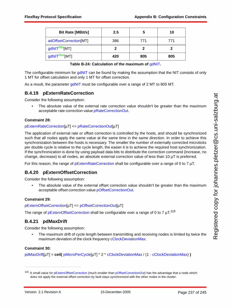
FlexRay Protocol Specification Appendix B: Configuration Constraints
Reg
iste
red
copy
for
joha
nnes
.ple
tzer
@cs
.uni
-sal
zbur
g.at
The configurable minimum for gdNIT can be found by making the assumption that the NIT consists of only1 MT for offset calculation and only 1 MT for offset correction.
As a result, the parameter gdNIT must be configurable over a range of 2 MT to 805 MT.
B.4.19 pExternRateCorrectionConsider the following assumption:
• The absolute value of the external rate correction value shouldn't be greater than the maximumacceptable rate correction value pRateCorrectionOut.
Constraint 28:
pExternRateCorrection[µT] <= pRateCorrectionOut[µT]
The application of external rate or offset correction is controlled by the hosts, and should be synchronizedsuch that all nodes apply the same value at the same time in the same direction. In order to achieve thissynchronization between the hosts is necessary. The smaller the number of externally corrected microticksper double cycle is relative to the cycle length, the easier it is to achieve the required host synchronization.If the synchronization is done by using payload data bits to distribute the correction command {increase, nochange, decrease} to all nodes, an absolute external correction value of less than 10 µT is preferred.
For this reason, the range of pExternRateCorrection shall be configurable over a range of 0 to 7 µT.
B.4.20 pExternOffsetCorrectionConsider the following assumption:
• The absolute value of the external offset correction value shouldn't be greater than the maximumacceptable offset correction value pOffsetCorrectionOut.
Constraint 29:
pExternOffsetCorrection[µT] <= pOffsetCorrectionOut[µT]
The range of pExternOffsetCorrection shall be configurable over a range of 0 to 7 µT.118
B.4.21 pdMaxDriftConsider the following assumption:
• The maximum drift of cycle length between transmitting and receiving nodes is limited by twice themaximum deviation of the clock frequency cClockDeviationMax.
Constraint 30:
pdMaxDrift[µT] = ceil( pMicroPerCycle[µT] * 2 * cClockDeviationMax / (1 - cClockDeviationMax) )
adOffsetCorrection[MT] 386 771 771
gdNITMin[MT] 2 2 2
gdNITMax[MT] 420 805 805
118 A small value for pExternOffsetCorrection (much smaller than pOffsetCorrectionOut) has the advantage that a node which does not apply the external offset correction by fault stays synchronized with the other nodes in the cluster.
Bit Rate [MBit/s] 2.5 5 10
Table B-24: Calculation of the maximum of gdNIT.
Version 2.1 Revision A 15-December-2005 Page 237 of 245
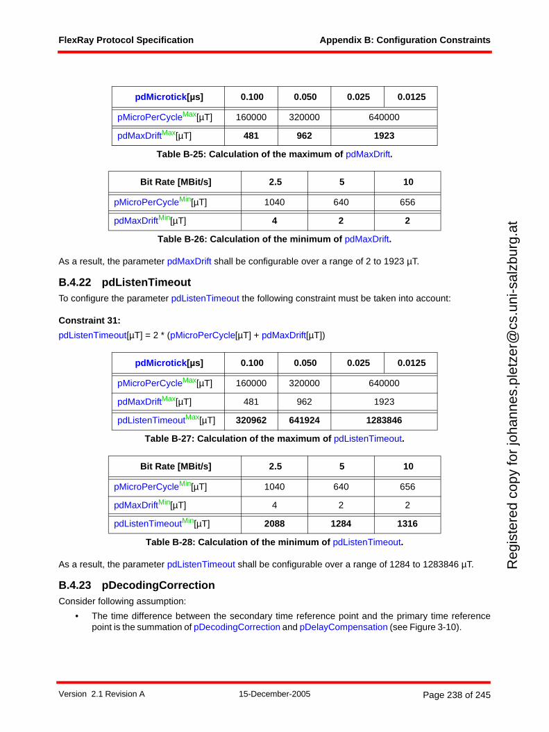
FlexRay Protocol Specification Appendix B: Configuration Constraints
Reg
iste
red
copy
for
joha
nnes
.ple
tzer
@cs
.uni
-sal
zbur
g.at
As a result, the parameter pdMaxDrift shall be configurable over a range of 2 to 1923 µT.
B.4.22 pdListenTimeoutTo configure the parameter pdListenTimeout the following constraint must be taken into account:
Constraint 31:
pdListenTimeout[µT] = 2 * (pMicroPerCycle[µT] + pdMaxDrift[µT])
As a result, the parameter pdListenTimeout shall be configurable over a range of 1284 to 1283846 µT.
B.4.23 pDecodingCorrectionConsider following assumption:
• The time difference between the secondary time reference point and the primary time referencepoint is the summation of pDecodingCorrection and pDelayCompensation (see Figure 3-10).
pdMicrotick[µs] 0.100 0.050 0.025 0.0125
pMicroPerCycleMax[µT] 160000 320000 640000
pdMaxDriftMax[µT] 481 962 1923
Table B-25: Calculation of the maximum of pdMaxDrift.
Bit Rate [MBit/s] 2.5 5 10
pMicroPerCycleMin[µT] 1040 640 656
pdMaxDriftMin[µT] 4 2 2
Table B-26: Calculation of the minimum of pdMaxDrift.
pdMicrotick[µs] 0.100 0.050 0.025 0.0125
pMicroPerCycleMax[µT] 160000 320000 640000
pdMaxDriftMax[µT] 481 962 1923
pdListenTimeoutMax[µT] 320962 641924 1283846
Table B-27: Calculation of the maximum of pdListenTimeout.
Bit Rate [MBit/s] 2.5 5 10
pMicroPerCycleMin[µT] 1040 640 656
pdMaxDriftMin[µT] 4 2 2
pdListenTimeoutMin[µT] 2088 1284 1316
Table B-28: Calculation of the minimum of pdListenTimeout.
Version 2.1 Revision A 15-December-2005 Page 238 of 245
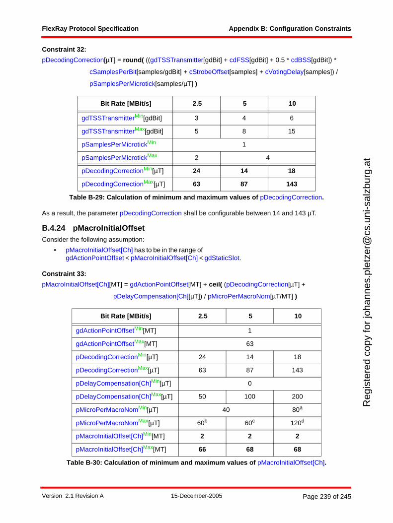
FlexRay Protocol Specification Appendix B: Configuration Constraints
Reg
iste
red
copy
for
joha
nnes
.ple
tzer
@cs
.uni
-sal
zbur
g.at
Constraint 32:
pDecodingCorrection[µT] = round( ((gdTSSTransmitter[gdBit] + cdFSS[gdBit] + 0.5 * cdBSS[gdBit]) *
cSamplesPerBit[samples/gdBit] + cStrobeOffset[samples] + cVotingDelay[samples]) /
pSamplesPerMicrotick[samples/µT] )
As a result, the parameter pDecodingCorrection shall be configurable between 14 and 143 µT.
B.4.24 pMacroInitialOffsetConsider the following assumption:
• pMacroInitialOffset[Ch] has to be in the range of gdActionPointOffset < pMacroInitialOffset[Ch] < gdStaticSlot.
Constraint 33:
pMacroInitialOffset[Ch][MT] = gdActionPointOffset[MT] + ceil( (pDecodingCorrection[µT] +
pDelayCompensation[Ch][µT]) / pMicroPerMacroNom[µT/MT] )
Bit Rate [MBit/s] 2.5 5 10
gdTSSTransmitterMin[gdBit] 3 4 6
gdTSSTransmitterMax[gdBit] 5 8 15
pSamplesPerMicrotickMin 1
pSamplesPerMicrotickMax 2 4
pDecodingCorrectionMin[µT] 24 14 18
pDecodingCorrectionMax[µT] 63 87 143
Table B-29: Calculation of minimum and maximum values of pDecodingCorrection.
Bit Rate [MBit/s] 2.5 5 10
gdActionPointOffsetMin[MT] 1
gdActionPointOffsetMax[MT] 63
pDecodingCorrectionMin[µT] 24 14 18
pDecodingCorrectionMax[µT] 63 87 143
pDelayCompensation[Ch]Min[µT] 0
pDelayCompensation[Ch]Max[µT] 50 100 200
pMicroPerMacroNomMin[µT] 40 80a
pMicroPerMacroNomMax[µT] 60b 60c 120d
pMacroInitialOffset[Ch]Min[MT] 2 2 2
pMacroInitialOffset[Ch]Max[MT] 66 68 68
Table B-30: Calculation of minimum and maximum values of pMacroInitialOffset[Ch].
Version 2.1 Revision A 15-December-2005 Page 239 of 245
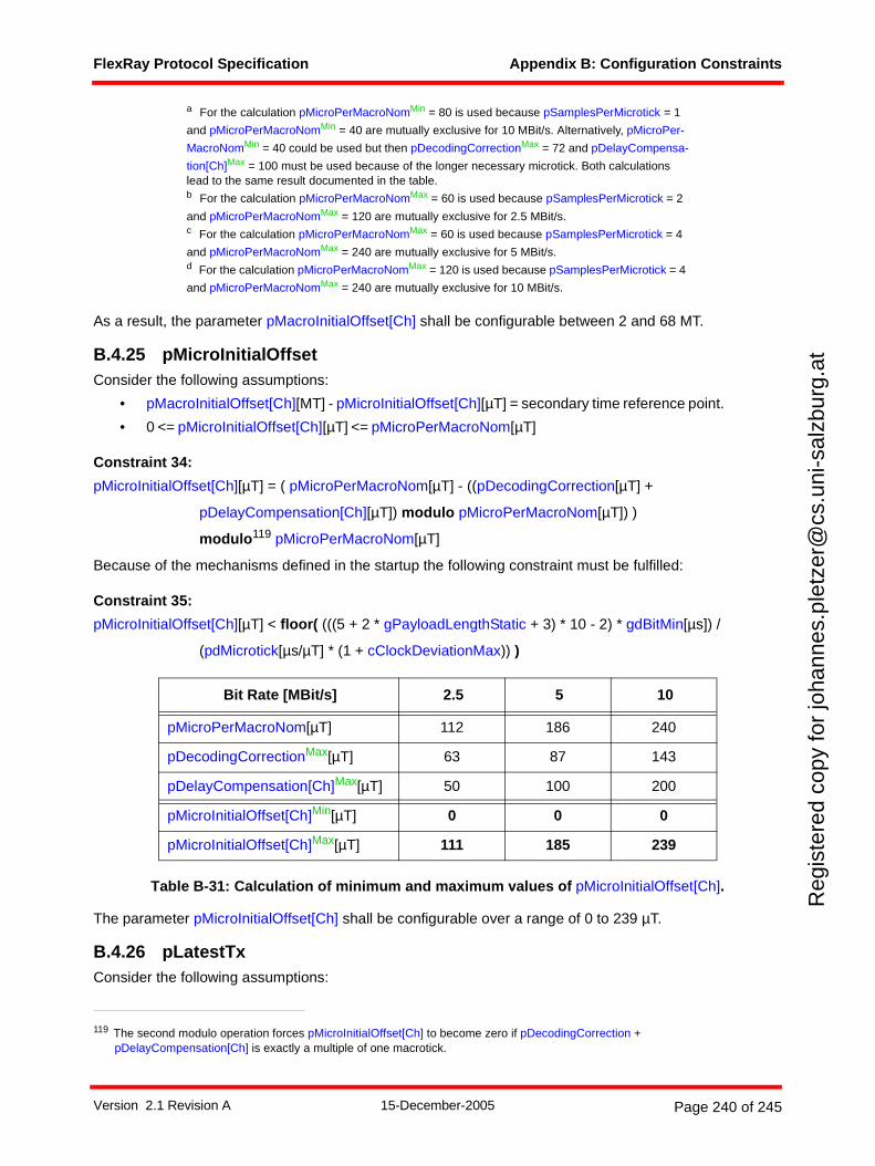
FlexRay Protocol Specification Appendix B: Configuration Constraints
Reg
iste
red
copy
for
joha
nnes
.ple
tzer
@cs
.uni
-sal
zbur
g.at
As a result, the parameter pMacroInitialOffset[Ch] shall be configurable between 2 and 68 MT.
B.4.25 pMicroInitialOffsetConsider the following assumptions:
• pMacroInitialOffset[Ch][MT] - pMicroInitialOffset[Ch][µT] = secondary time reference point.
• 0 <= pMicroInitialOffset[Ch][µT] <= pMicroPerMacroNom[µT]
Constraint 34:
pMicroInitialOffset[Ch][µT] = ( pMicroPerMacroNom[µT] - ((pDecodingCorrection[µT] +
pDelayCompensation[Ch][µT]) modulo pMicroPerMacroNom[µT]) )
modulo119 pMicroPerMacroNom[µT]
Because of the mechanisms defined in the startup the following constraint must be fulfilled:
Constraint 35:
pMicroInitialOffset[Ch][µT] < floor( (((5 + 2 * gPayloadLengthStatic + 3) * 10 - 2) * gdBitMin[µs]) /
(pdMicrotick[µs/µT] * (1 + cClockDeviationMax)) )
Table B-31: Calculation of minimum and maximum values of pMicroInitialOffset[Ch].
The parameter pMicroInitialOffset[Ch] shall be configurable over a range of 0 to 239 µT.
B.4.26 pLatestTxConsider the following assumptions:
a For the calculation pMicroPerMacroNomMin = 80 is used because pSamplesPerMicrotick = 1
and pMicroPerMacroNomMin = 40 are mutually exclusive for 10 MBit/s. Alternatively, pMicroPer-
MacroNomMin = 40 could be used but then pDecodingCorrectionMax = 72 and pDelayCompensa-
tion[Ch]Max = 100 must be used because of the longer necessary microtick. Both calculations lead to the same result documented in the table.b For the calculation pMicroPerMacroNomMax = 60 is used because pSamplesPerMicrotick = 2
and pMicroPerMacroNomMax = 120 are mutually exclusive for 2.5 MBit/s.c For the calculation pMicroPerMacroNomMax = 60 is used because pSamplesPerMicrotick = 4
and pMicroPerMacroNomMax = 240 are mutually exclusive for 5 MBit/s.d For the calculation pMicroPerMacroNomMax = 120 is used because pSamplesPerMicrotick = 4
and pMicroPerMacroNomMax = 240 are mutually exclusive for 10 MBit/s.
119 The second modulo operation forces pMicroInitialOffset[Ch] to become zero if pDecodingCorrection + pDelayCompensation[Ch] is exactly a multiple of one macrotick.
Bit Rate [MBit/s] 2.5 5 10
pMicroPerMacroNom[µT] 112 186 240
pDecodingCorrectionMax[µT] 63 87 143
pDelayCompensation[Ch]Max[µT] 50 100 200
pMicroInitialOffset[Ch]Min[µT] 0 0 0
pMicroInitialOffset[Ch]Max[µT] 111 185 239
Version 2.1 Revision A 15-December-2005 Page 240 of 245
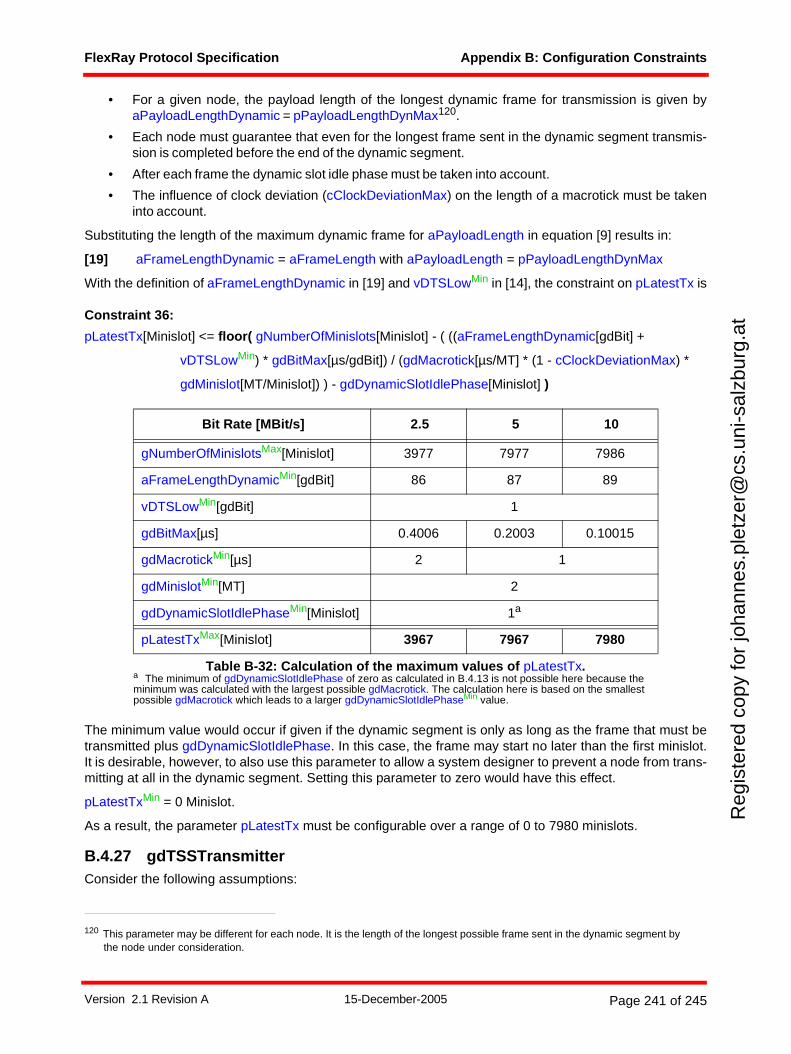
FlexRay Protocol Specification Appendix B: Configuration Constraints
Reg
iste
red
copy
for
joha
nnes
.ple
tzer
@cs
.uni
-sal
zbur
g.at
• For a given node, the payload length of the longest dynamic frame for transmission is given byaPayloadLengthDynamic = pPayloadLengthDynMax120.
• Each node must guarantee that even for the longest frame sent in the dynamic segment transmis-sion is completed before the end of the dynamic segment.
• After each frame the dynamic slot idle phase must be taken into account.
• The influence of clock deviation (cClockDeviationMax) on the length of a macrotick must be takeninto account.
Substituting the length of the maximum dynamic frame for aPayloadLength in equation [9] results in:
[19] aFrameLengthDynamic = aFrameLength with aPayloadLength = pPayloadLengthDynMax
With the definition of aFrameLengthDynamic in [19] and vDTSLowMin in [14], the constraint on pLatestTx is
Constraint 36:
pLatestTx[Minislot] <= floor( gNumberOfMinislots[Minislot] - ( ((aFrameLengthDynamic[gdBit] +
vDTSLowMin) * gdBitMax[µs/gdBit]) / (gdMacrotick[µs/MT] * (1 - cClockDeviationMax) *
gdMinislot[MT/Minislot]) ) - gdDynamicSlotIdlePhase[Minislot] )
The minimum value would occur if given if the dynamic segment is only as long as the frame that must betransmitted plus gdDynamicSlotIdlePhase. In this case, the frame may start no later than the first minislot.It is desirable, however, to also use this parameter to allow a system designer to prevent a node from trans-mitting at all in the dynamic segment. Setting this parameter to zero would have this effect.
pLatestTxMin = 0 Minislot.
As a result, the parameter pLatestTx must be configurable over a range of 0 to 7980 minislots.
B.4.27 gdTSSTransmitterConsider the following assumptions:
120 This parameter may be different for each node. It is the length of the longest possible frame sent in the dynamic segment by the node under consideration.
Bit Rate [MBit/s] 2.5 5 10
gNumberOfMinislotsMax[Minislot] 3977 7977 7986
aFrameLengthDynamicMin[gdBit] 86 87 89
vDTSLowMin[gdBit] 1
gdBitMax[µs] 0.4006 0.2003 0.10015
gdMacrotickMin[µs] 2 1
gdMinislotMin[MT] 2
gdDynamicSlotIdlePhaseMin[Minislot] 1a
a The minimum of gdDynamicSlotIdlePhase of zero as calculated in B.4.13 is not possible here because the minimum was calculated with the largest possible gdMacrotick. The calculation here is based on the smallest possible gdMacrotick which leads to a larger gdDynamicSlotIdlePhaseMin value.
pLatestTxMax[Minislot] 3967 7967 7980
Table B-32: Calculation of the maximum values of pLatestTx.
Version 2.1 Revision A 15-December-2005 Page 241 of 245
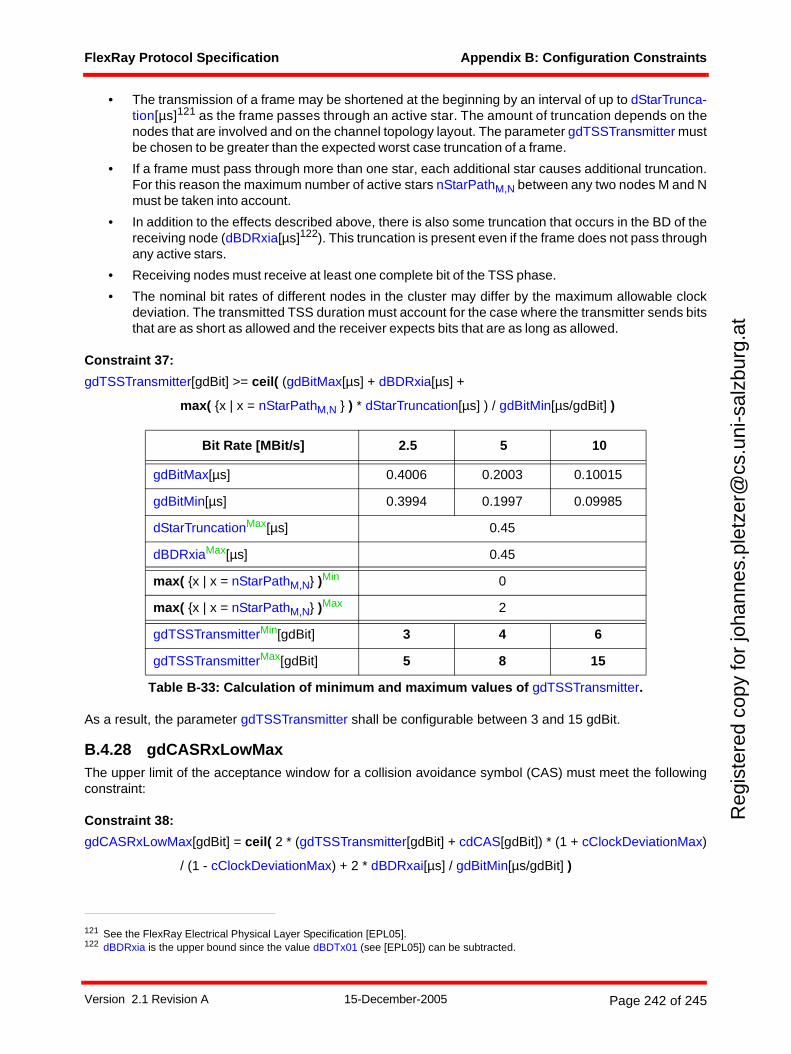
FlexRay Protocol Specification Appendix B: Configuration Constraints
Reg
iste
red
copy
for
joha
nnes
.ple
tzer
@cs
.uni
-sal
zbur
g.at
• The transmission of a frame may be shortened at the beginning by an interval of up to dStarTrunca-tion[µs]121 as the frame passes through an active star. The amount of truncation depends on thenodes that are involved and on the channel topology layout. The parameter gdTSSTransmitter mustbe chosen to be greater than the expected worst case truncation of a frame.
• If a frame must pass through more than one star, each additional star causes additional truncation.For this reason the maximum number of active stars nStarPathM,N between any two nodes M and Nmust be taken into account.
• In addition to the effects described above, there is also some truncation that occurs in the BD of thereceiving node (dBDRxia[µs]122). This truncation is present even if the frame does not pass throughany active stars.
• Receiving nodes must receive at least one complete bit of the TSS phase.
• The nominal bit rates of different nodes in the cluster may differ by the maximum allowable clockdeviation. The transmitted TSS duration must account for the case where the transmitter sends bitsthat are as short as allowed and the receiver expects bits that are as long as allowed.
Constraint 37:
gdTSSTransmitter[gdBit] >= ceil( (gdBitMax[µs] + dBDRxia[µs] +
max( {x | x = nStarPathM,N } ) * dStarTruncation[µs] ) / gdBitMin[µs/gdBit] )
As a result, the parameter gdTSSTransmitter shall be configurable between 3 and 15 gdBit.
B.4.28 gdCASRxLowMaxThe upper limit of the acceptance window for a collision avoidance symbol (CAS) must meet the followingconstraint:
Constraint 38:
gdCASRxLowMax[gdBit] = ceil( 2 * (gdTSSTransmitter[gdBit] + cdCAS[gdBit]) * (1 + cClockDeviationMax)
/ (1 - cClockDeviationMax) + 2 * dBDRxai[µs] / gdBitMin[µs/gdBit] )
121 See the FlexRay Electrical Physical Layer Specification [EPL05].122 dBDRxia is the upper bound since the value dBDTx01 (see [EPL05]) can be subtracted.
Bit Rate [MBit/s] 2.5 5 10
gdBitMax[µs] 0.4006 0.2003 0.10015
gdBitMin[µs] 0.3994 0.1997 0.09985
dStarTruncationMax[µs] 0.45
dBDRxiaMax[µs] 0.45
max( {x | x = nStarPathM,N} )Min 0
max( {x | x = nStarPathM,N} )Max 2
gdTSSTransmitterMin[gdBit] 3 4 6
gdTSSTransmitterMax[gdBit] 5 8 15
Table B-33: Calculation of minimum and maximum values of gdTSSTransmitter.
Version 2.1 Revision A 15-December-2005 Page 242 of 245
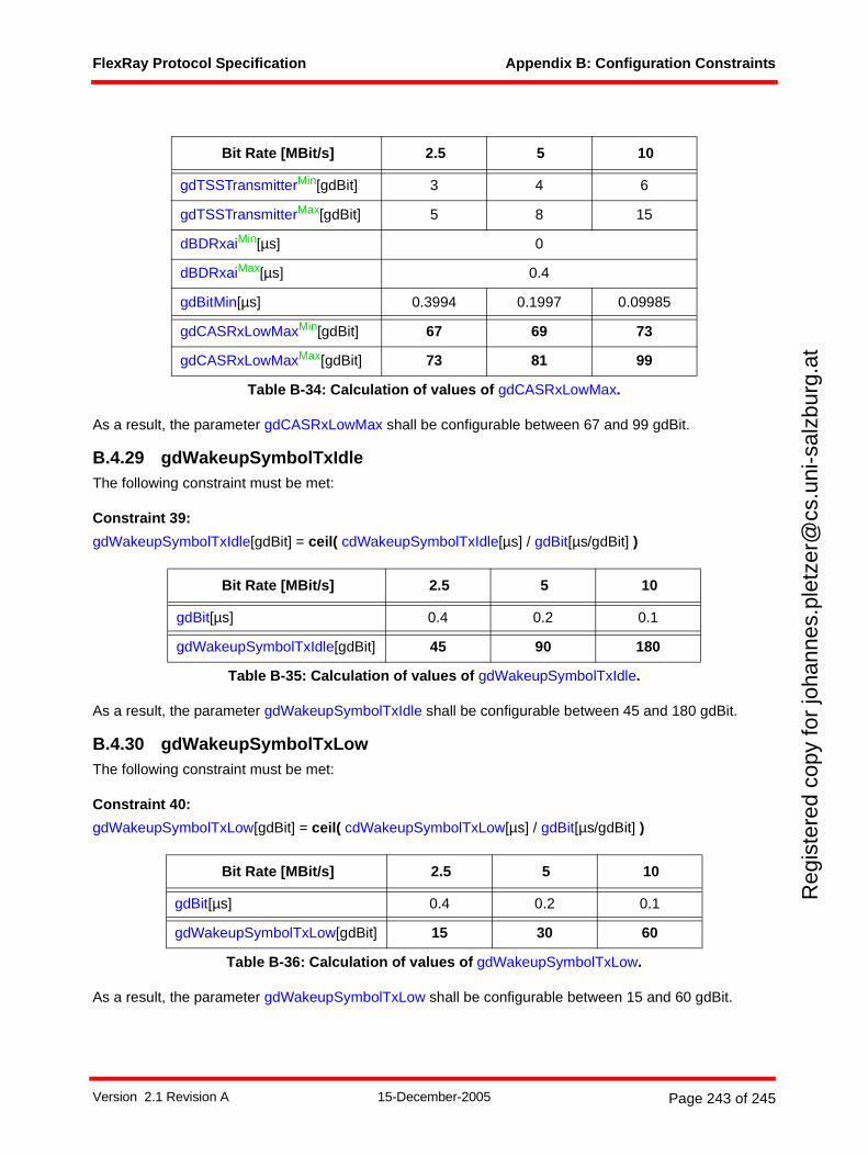
FlexRay Protocol Specification Appendix B: Configuration Constraints
Reg
iste
red
copy
for
joha
nnes
.ple
tzer
@cs
.uni
-sal
zbur
g.at
As a result, the parameter gdCASRxLowMax shall be configurable between 67 and 99 gdBit.
B.4.29 gdWakeupSymbolTxIdleThe following constraint must be met:
Constraint 39:
gdWakeupSymbolTxIdle[gdBit] = ceil( cdWakeupSymbolTxIdle[µs] / gdBit[µs/gdBit] )
As a result, the parameter gdWakeupSymbolTxIdle shall be configurable between 45 and 180 gdBit.
B.4.30 gdWakeupSymbolTxLowThe following constraint must be met:
Constraint 40:
gdWakeupSymbolTxLow[gdBit] = ceil( cdWakeupSymbolTxLow[µs] / gdBit[µs/gdBit] )
As a result, the parameter gdWakeupSymbolTxLow shall be configurable between 15 and 60 gdBit.
Bit Rate [MBit/s] 2.5 5 10
gdTSSTransmitterMin[gdBit] 3 4 6
gdTSSTransmitterMax[gdBit] 5 8 15
dBDRxaiMin[µs] 0
dBDRxaiMax[µs] 0.4
gdBitMin[µs] 0.3994 0.1997 0.09985
gdCASRxLowMaxMin[gdBit] 67 69 73
gdCASRxLowMaxMax[gdBit] 73 81 99
Table B-34: Calculation of values of gdCASRxLowMax.
Bit Rate [MBit/s] 2.5 5 10
gdBit[µs] 0.4 0.2 0.1
gdWakeupSymbolTxIdle[gdBit] 45 90 180
Table B-35: Calculation of values of gdWakeupSymbolTxIdle.
Bit Rate [MBit/s] 2.5 5 10
gdBit[µs] 0.4 0.2 0.1
gdWakeupSymbolTxLow[gdBit] 15 30 60
Table B-36: Calculation of values of gdWakeupSymbolTxLow.
Version 2.1 Revision A 15-December-2005 Page 243 of 245
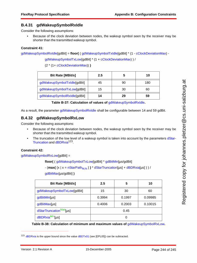
FlexRay Protocol Specification Appendix B: Configuration Constraints
Reg
iste
red
copy
for
joha
nnes
.ple
tzer
@cs
.uni
-sal
zbur
g.at
B.4.31 gdWakeupSymbolRxIdleConsider the following assumptions:
• Because of the clock deviation between nodes, the wakeup symbol seen by the receiver may beshorter than the transmitted wakeup symbol.
Constraint 41:
gdWakeupSymbolRxIdle[gdBit] = floor( ( gdWakeupSymbolTxIdle[gdBit] * (1 - cClockDeviationMax) -
gdWakeupSymbolTxLow[gdBit] * (1 + cClockDeviationMax) ) /
(2 * (1+ cClockDeviationMax)) )
As a result, the parameter gdWakeupSymbolRxIdle shall be configurable between 14 and 59 gdBit.
B.4.32 gdWakeupSymbolRxLowConsider the following assumptions:
• Because of the clock deviation between nodes, the wakeup symbol seen by the receiver may beshorter than the transmitted wakeup symbol.
• The truncation of the low level of a wakeup symbol is taken into account by the parameters dStar-Truncation and dBDRxia123.
Constraint 42:
gdWakeupSymbolRxLow[gdBit] =
floor( ( gdWakeupSymbolTxLow[gdBit] * gdBitMin[µs/gdBit]
- (max( {x | x = nStarPathM,N } ) * dStarTruncation[µs] + dBDRxia[µs] ) ) /
gdBitMax[µs/gdBit] )
Bit Rate [MBit/s] 2.5 5 10
gdWakeupSymbolTxIdle[gdBit] 45 90 180
gdWakeupSymbolTxLow[gdBit] 15 30 60
gdWakeupSymbolRxIdle[gdBit] 14 29 59
Table B-37: Calculation of values of gdWakeupSymbolRxIdle.
123 dBDRxia is the upper bound since the value dBDTx01 (see [EPL05]) can be subtracted.
Bit Rate [MBit/s] 2.5 5 10
gdWakeupSymbolTxLow[gdBit] 15 30 60
gdBitMin[µs] 0.3994 0.1997 0.09985
gdBitMax[µs] 0.4006 0.2003 0.10015
dStarTruncationMax[µs] 0.45
dBDRxiaMin[µs] 0
Table B-38: Calculation of minimum and maximum values of gdWakeupSymbolRxLow.
Version 2.1 Revision A 15-December-2005 Page 244 of 245
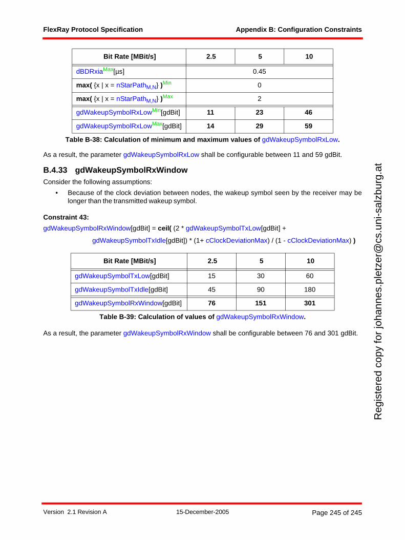
FlexRay Protocol Specification Appendix B: Configuration Constraints
Reg
iste
red
copy
for
joha
nnes
.ple
tzer
@cs
.uni
-sal
zbur
g.at
As a result, the parameter gdWakeupSymbolRxLow shall be configurable between 11 and 59 gdBit.
B.4.33 gdWakeupSymbolRxWindowConsider the following assumptions:
• Because of the clock deviation between nodes, the wakeup symbol seen by the receiver may belonger than the transmitted wakeup symbol.
Constraint 43:
gdWakeupSymbolRxWindow[gdBit] = ceil( (2 * gdWakeupSymbolTxLow[gdBit] +
gdWakeupSymbolTxIdle[gdBit]) * (1+ cClockDeviationMax) / (1 - cClockDeviationMax) )
As a result, the parameter gdWakeupSymbolRxWindow shall be configurable between 76 and 301 gdBit.
dBDRxiaMax[µs] 0.45
max( {x | x = nStarPathM,N} )Min 0
max( {x | x = nStarPathM,N} )Max 2
gdWakeupSymbolRxLowMin[gdBit] 11 23 46
gdWakeupSymbolRxLowMax[gdBit] 14 29 59
Bit Rate [MBit/s] 2.5 5 10
gdWakeupSymbolTxLow[gdBit] 15 30 60
gdWakeupSymbolTxIdle[gdBit] 45 90 180
gdWakeupSymbolRxWindow[gdBit] 76 151 301
Table B-39: Calculation of values of gdWakeupSymbolRxWindow.
Bit Rate [MBit/s] 2.5 5 10
Table B-38: Calculation of minimum and maximum values of gdWakeupSymbolRxLow.
Version 2.1 Revision A 15-December-2005 Page 245 of 245


![FlexRay Preliminary Central Bus Guardian Specification V2[1].0.9](https://img.pdfslide.us/doc/110x75/552ae18f550346b63a8b45ec/flexray-preliminary-central-bus-guardian-specification-v2109.jpg)