Embed Size (px)
Citation preview
FlexMove FS (65 mm) Conveyor System
Installation, Maintenance & Parts Manual
851-900 Rev. A
For other service manuals visit our website at:www.dornerconveyors.com/manuals-literature
Record Conveyor Serial Number Here
Table of ContentsIntroduction ......................................................................... 4Warnings − General Safety ................................................. 5Product Description ............................................................. 6Specifications ...................................................................... 7
Conveyor Supports: ......................................................... 7Maximum Distances:.................................................... 7
Installation ........................................................................... 8Introduction...................................................................... 8Document Disposition ..................................................... 8Initial Assembly Planning................................................ 8Safeguarding .................................................................... 8Considerations ................................................................. 8End Drive Unit................................................................. 8Idler Unit.......................................................................... 8Catenary Drive Unit......................................................... 8Assembly Order ............................................................... 8Tools General................................................................... 8
Tools............................................................................. 8Hand Tools ................................................................... 9Power Tools.................................................................. 9
Fasteners .......................................................................... 9Standard Fasteners........................................................ 9Square Nut.................................................................... 9Spring Nuts................................................................... 9Connecting Strip........................................................... 9T-Bolt ......................................................................... 10
Pre installation Information ........................................... 10Cutting FlexMove Beam ............................................ 10Saw Requirements...................................................... 10Working Site .............................................................. 10Quality of Cut............................................................. 10Assembly.................................................................... 10
Foot Installation ............................................................. 11Conveyor Installation..................................................... 12
Option 1...................................................................... 12Option 2...................................................................... 12Option 3...................................................................... 12
Mounting Conveyor Beam Support Bracket ................. 12Conveyor Beam Installation .......................................... 13Drive Unit and Idler End Unit Installation .................... 14
Drive End ................................................................... 14Drive Tail Support Brackets....................................... 14Idler End..................................................................... 14
Attaching Slide Rail in Straight Beam........................... 15Slide Rail End Installation at Connector Beam ............. 16Slide Rail Installation at Wheel Bend............................ 17Slide Rail Installation at Horizontal Plain Bends and Vertical Bend .......................................................... 17Drilling Slide Rail .......................................................... 17Fixing Slide Rail ............................................................ 18
Nylon Screw............................................................... 18Aluminum Rivet ......................................................... 19
Checking Slide Rail and Rivet Condition After Fixed .. 19Joining Chain End.......................................................... 19Chain Installation at Drive Unit..................................... 20
Chain Assembly at Chain Disconnecting Module FSCC................................................................. 21Weighted Take-Up ......................................................... 22Top Running Drive......................................................... 23Install Guiding ................................................................ 24
Length Adjustment of the Conveyor Chain................ 24End Drive Units and Catenary Drive Units............. 24Intermediate Drive Units and Horizontal Bend Drive Unit .................................... 24
Guide Rail System Installation ................................... 24High Side Guiding ...................................................... 25Heavy Duty Fully Adjustable Guiding ....................... 25Puck/Pallet Guiding .................................................... 27Adjustable Guide Rail Bracket ................................... 28
Assembly with Different Guide Rail Support ......... 28FGRF- 42x18V Guide Rail Bracket Assembly .......... 29
Assembly with Different Guide Rail Support ......... 29FGRF- 42x18V Spacer Assembly .............................. 30FGRB- 40x18, FGRB- 40x20 and FGRB- 40x15x20 Guide Rail Bracket Assembly....... 30
Method 1 ................................................................. 30Assembly with Different Guide Rail Support ......... 31Method 2 ................................................................. 31
Fixed Guide Rail Bracket Installation ........................ 32Guide Rail Connecting Installation............................. 32
Rail Connecting....................................................... 32Connecting Plug ...................................................... 32
Guide Rail Cover Installation ..................................... 33Final Preparations........................................................... 33
Plug Beam Ends.......................................................... 33Anchor Feet to the Floor............................................. 33Other Preparations ...................................................... 33
Start-Up and Testing ...................................................... 33Safety Considerations ................................................. 33
Safeguarding can be achieved by:........................... 34Torque Limiter Adjustment for Suspended Drive Units ............................................... 34
Introduction ............................................................. 34Name of Parts .......................................................... 34
Torque Setting............................................................. 34Replace the Friction Facing ........................................ 34Maintenance and Precautions after the Replacement Procedure ................................ 34Safety .......................................................................... 34
Preventive Maintenance and Adjustment .......................... 35Start-Up and Maintenance Schedule .............................. 35Chain Lubrication........................................................... 35Wear ............................................................................... 35Chain Elongation ............................................................ 35Inspection ....................................................................... 36Drive Unit....................................................................... 36
Dorner Mfg. Corp. 2 851-900 Rev. A
FlexMove FS (65 mm) Conveyor System
Table of Contents
Maintenance Schedule.................................................... 36First 3rd Month, 6th Month, and Every 6th Month Following........................................ 36Checking Slide Rail with the Conveyor Chain in Place ............................................ 36Checks When the Chain is Removed.......................... 37Horizontal Bends ........................................................ 37Safety Devices ............................................................ 37
Troubleshooting.............................................................. 38Required Tools ............................................................... 39 Conveyor Chain Replacement....................................... 39
Replacing a Section or Entire Chain........................... 39Conveyor Chain Tensioning........................................... 40Slide Rail Replacement .................................................. 40Idler Pulley Replacement ............................................... 40Drive Spindle Shaft Replacement .................................. 41Retaining Guide Replacement........................................ 42
Cantenary Drive End .................................................. 42Idler End and GP Drive Tail ....................................... 43
Top Running Drive......................................................... 44Wheel Bend Servicing.................................................... 45Weighted Take-Up ......................................................... 46Power Transfer ............................................................... 48
Removal ...................................................................... 48Installation .................................................................. 51
Service Parts....................................................................... 54Drive Tail........................................................................ 54Guided Profile (GP) Drive Tail ...................................... 56FSSD-A65 Suspended Drive.......................................... 58FSID-DD-0L1/0R1 Intermediate Direct Drive .............. 60FSID-SD-0L1/0R1 Intermediate Suspended Drive........ 61Weighted Take-Up ......................................................... 62Idler Tail ......................................................................... 64Top Running Drive......................................................... 66Frame Assembly............................................................. 68Curve Frame Assembly .................................................. 69Knuckle Frame Assembly .............................................. 70#4 & #5 High Sides for Straight Modules ...................... 71#4 & #5 High Sides for Curve Modules......................... 72#4 & #5 High Sides for Incline/Decline Modules .......... 73#13 & #14 Heavy Duty Fully Adjustable Guiding......... 74#17 & #18 - Puck / Pallet Guiding ................................. 75Type A - Fixed Guiding (16x54).................................... 76Type B - Fixed Guiding (16x42) .................................... 76Type C - Fixed Guiding (28x42) .................................... 77Type D - Fixed Guiding (40x42).................................... 77Type E - Fixed Guiding (49x42) .................................... 78Type F - Fixed Guiding (53x42) .................................... 78Type G - Fixed Guiding (90x42).................................... 79Type H - Adjustable Width Guiding (8x39x45)............. 79Type J - Adjustable Width Guiding (26x39x45)............ 80Type K - Adjustable Width Guiding (40x18)................. 80Type L - Adjustable Height Guiding (18x110) .............. 81Type M - Adjustable Height Guiding (18x150) ............. 81Type N - Fully Adjustable Guiding................................ 82Type P - Fully Adjustable Guiding ................................ 82
Type Q - Dual Rail Guiding........................................... 83Type R - Dual Rail Guiding........................................... 83Type S - Adjustable Height Guiding.............................. 84Power Transfer............................................................... 85Horizontal Mounting Brackets....................................... 86Support Post - Conveyor Frame Mount ........................ 87Support Post - Motor Mount ......................................... 88Suspended Drive Stand ................................................. 89Dual Side Support Post ................................................. 90E-Drive Gearmotor Mounting Package ......................... 91Standard Load 90° Industrial Gearmotors ..................... 92Flange Mounted Motor (Direct Drive Tail) ................... 93Foot Mounted Motor (Suspended Drive Tail) ............... 94Slide Rail Replacement Tool ......................................... 95Slide Rail........................................................................ 95Replacement Chain ........................................................ 95Belt Removal Tool ......................................................... 96Side Cutter...................................................................... 96Utility Cutter .................................................................. 96Bearing Tool .................................................................. 96Notes .............................................................................. 97Return Policy.................................................................. 98
851-900 Rev. A 3 Dorner Mfg. Corp.
FlexMove FS (65 mm) Conveyor System
Introduction
Upon receipt of shipment:� Compare shipment with packing slip. Contact factory
regarding discrepancies.� Inspect packages for shipping damage. Contact carrier
regarding damage.� Accessories may be shipped loose. See accessory instruc-
tions for installation.Dorner�s Limited Warranty applies.
Dorner has convenient, pre−configured kits of Key Service Parts for all conveyor products. These time saving kits are easy to order, designed for fast installation, and guarantee you will have what you need when you need it. Key Parts and Kits are marked in the Service Parts section of this manual with the Performance Parts Kits logo .Dorner reserves the right to make changes at any time without notice or obligation.
IMPORTANTSome illustrations may show guards removed. DO NOT operate equipment without guards.
Dorner Mfg. Corp. 4 851-900 Rev. A
FlexMove FS (65 mm) Conveyor System
Warnings − General Safety
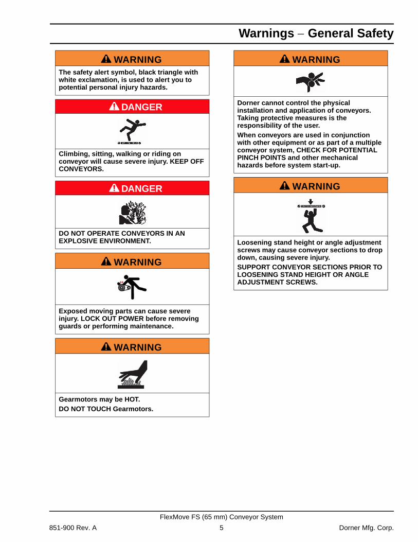
A WARNINGThe safety alert symbol, black triangle with white exclamation, is used to alert you to potential personal injury hazards.
A DANGER
Climbing, sitting, walking or riding on conveyor will cause severe injury. KEEP OFF CONVEYORS.
A DANGER
DO NOT OPERATE CONVEYORS IN AN EXPLOSIVE ENVIRONMENT.
A WARNING
Exposed moving parts can cause severe injury. LOCK OUT POWER before removing guards or performing maintenance.
A WARNING
Gearmotors may be HOT.DO NOT TOUCH Gearmotors.
A WARNING
Dorner cannot control the physical installation and application of conveyors. Taking protective measures is the responsibility of the user.When conveyors are used in conjunction with other equipment or as part of a multiple conveyor system, CHECK FOR POTENTIAL PINCH POINTS and other mechanical hazards before system start-up.
A WARNING
Loosening stand height or angle adjustment screws may cause conveyor sections to drop down, causing severe injury.SUPPORT CONVEYOR SECTIONS PRIOR TO LOOSENING STAND HEIGHT OR ANGLE ADJUSTMENT SCREWS.
851-900 Rev. A 5 Dorner Mfg. Corp.
FlexMove FS (65 mm) Conveyor System
Product Description
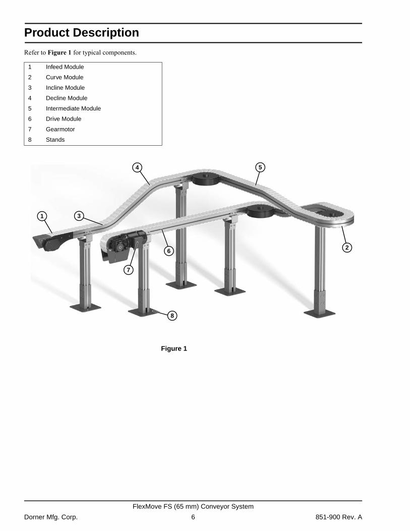
Refer to Figure 1 for typical components.
Figure 1
Figure 1
1 Infeed Module
2 Curve Module
3 Incline Module
4 Decline Module
5 Intermediate Module
6 Drive Module
7 Gearmotor
8 Stands
31
2
4
6
5
8
7
Dorner Mfg. Corp. 6 851-900 Rev. A
FlexMove FS (65 mm) Conveyor System
Specifications
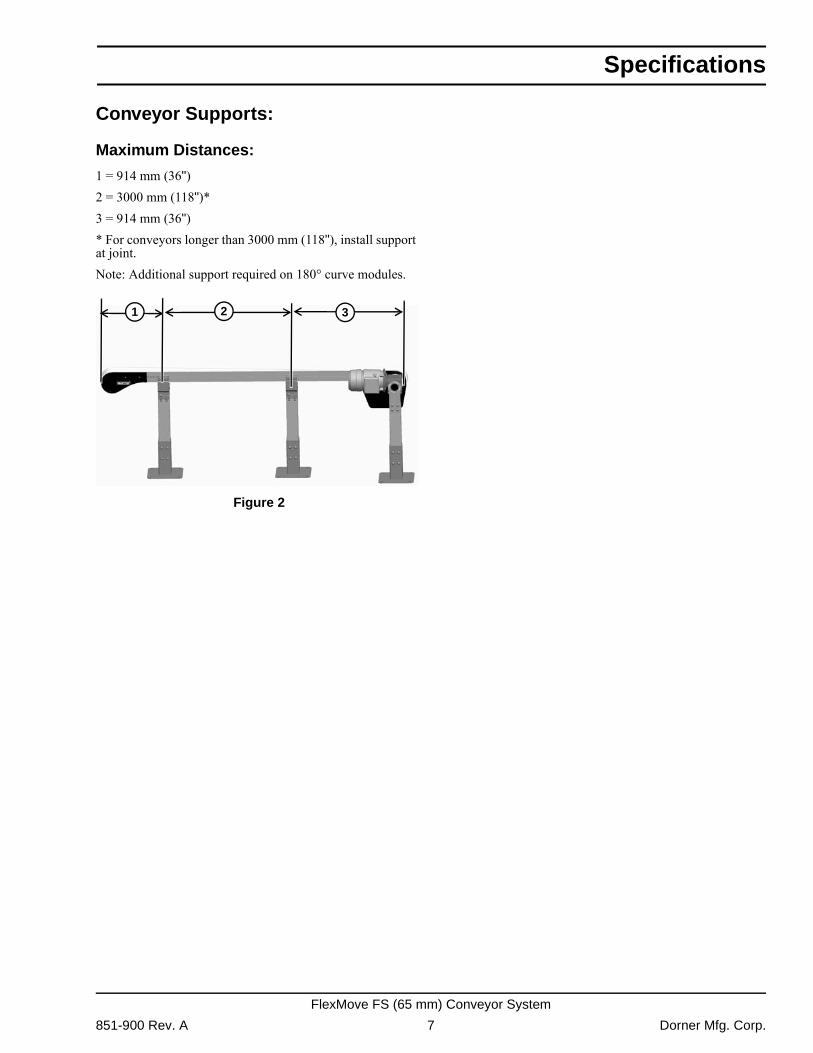
Conveyor Supports:
Maximum Distances:
1 = 914 mm (36")2 = 3000 mm (118")*3 = 914 mm (36")* For conveyors longer than 3000 mm (118"), install support at joint.Note: Additional support required on 180° curve modules.
Figure 2
Figure 2
321
851-900 Rev. A 7 Dorner Mfg. Corp.
FlexMove FS (65 mm) Conveyor System
Installation
IntroductionThe main purpose of this manual is to help self-building end users, with little or no prior experience, to assemble a FlexMove conveyor system. Each chapter includes detailed instructions and pictures showing how to assemble the different parts. Most pictures in the manual include parts from the FS conveyor system, but all instructions are applicable to the FH, FK, FS, FM, FC, FL, FU and FV.
Document DispositionThe document is divided into the following five main parts:� Installation site preparations� Tools and fasteners� Assembly � Start-up and testing
Initial Assembly PlanningSystematically working planning is required:� Fully understand and studying the assembly drawing.� Ensure the necessary tools are required.� Ensure all the parts and materials are well prepared in
advance, following the parts list.� Enough space for conveyor installation is important.� Ensure the floor is even and so the foot can be properly
attached on the floor.
SafeguardingAll pinch and shear points, as well as other exposed moving parts that present a hazard to users, is recommended to be safe guarded. Cleat conveyor chain is more susceptible of creating pinch and shear points than plain chain.When two or more pieces of equipment are interfaced, special attention must be given to the interfaced area to ensure proper safeguarding.For overhead conveyors, guards must be provided if products fall off the conveyor for some reason. The same applies to all incline, decline and vertical conveyors.
ConsiderationsWhen correctly applied, the conveyor components are safe to use or maintain. It is, however, necessary for those responsible to design, installation, operation and maintenance to be aware of certain areas when special caution is required.
End Drive UnitThe chain slack of a normal direct drive unit must be maintained during the system lifetime.
Idler UnitThe opening between links (when they turn around idler) could be a potential risk. The idler end should not be accessible during conveyor operation.
Catenary Drive UnitThe bridge area where the chain goes down should not be accessible during conveyor operation.
Assembly OrderDuring the conveyor assembly, the following items can be used as a checklist:� Cut all beams to desired length.� Connect all feet and structural beams.� Mount conveyor beam support brackets. � Assembly conveyor beams and mount them onto the sup-
port structure.� Mount drive and idler unit at the end of the conveyor.� Mount slide rail onto the conveyor beam.� Loosen the slip clutch at the drive unit.� Check any obstruction of the conveyor with a short piece
chain.� Assemble and mount necessary chain onto the conveyor.� Mount guide rail and other accessories required onto the
conveyor.� Tighten the slip clutch with suitable friction.� Read the final preparations at the end of this manual.
Tools General
Tools
To assemble a FlexMove Conveyor, you may need most of the tools listed on the following page. Not all are essential, but they will make your work easier and efficient.
Dorner Mfg. Corp. 8 851-900 Rev. A
FlexMove FS (65 mm) Conveyor System
Installation
Hand Tools� Wrench� Slide rail cutter� Set of metric hex keys� Counter sink bit� Drill fixtures for slide rail� Riveting tool� In addition, the tools listed below can be useful:- Files- Socket wrench- Screwdriver- Pliers- Knife (burr of slide rail)- Flush cutting pliers- Soft head hammer- Chain tools (for chain installation and dismantle)- Level
Power Tools� Hand drill� Drill bit (for fixing slide rail)
Fasteners
Standard Fasteners
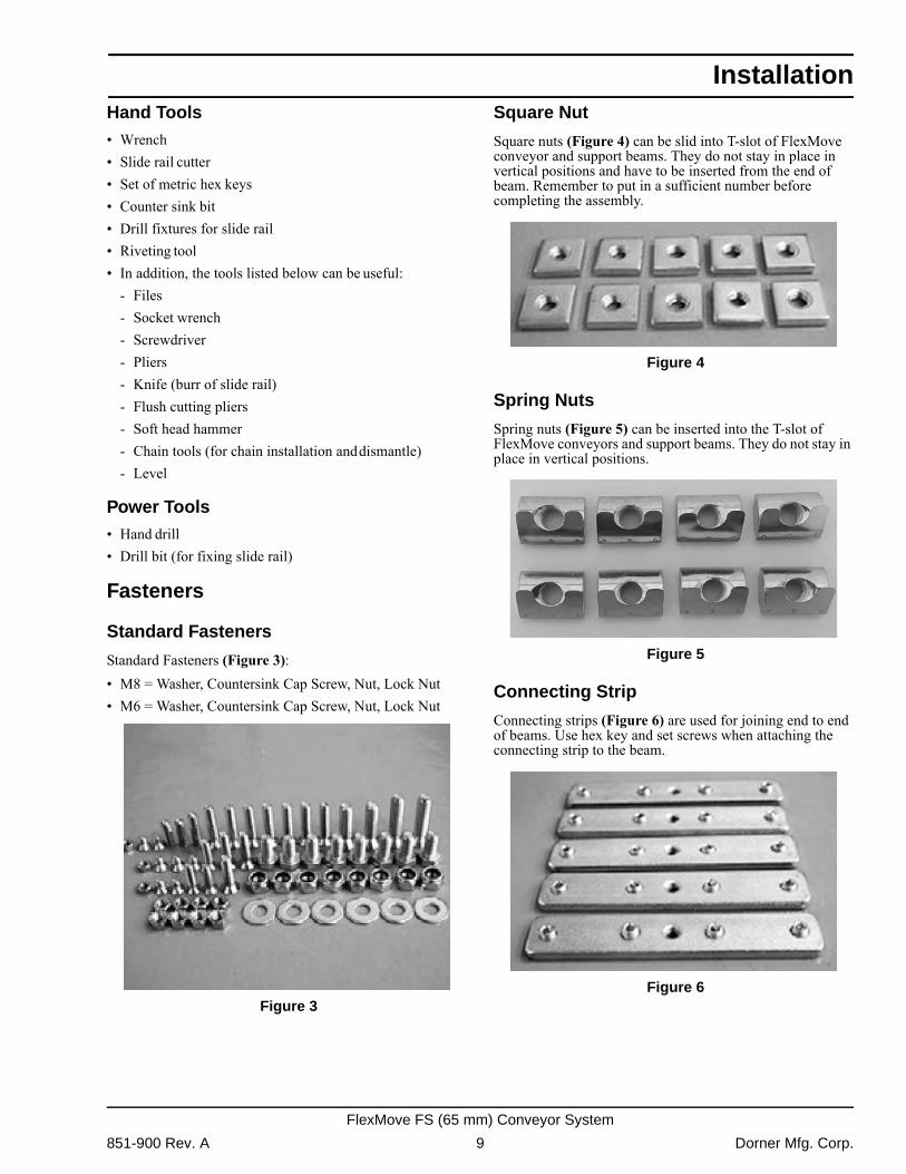
Standard Fasteners (Figure 3):� M8 = Washer, Countersink Cap Screw, Nut, Lock Nut� M6 = Washer, Countersink Cap Screw, Nut, Lock Nut
Figure 3
Figure 3
Square Nut
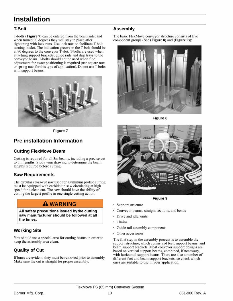
Square nuts (Figure 4) can be slid into T-slot of FlexMove conveyor and support beams. They do not stay in place in vertical positions and have to be inserted from the end of beam. Remember to put in a sufficient number before completing the assembly.
Figure 4
Figure 4
Spring Nuts
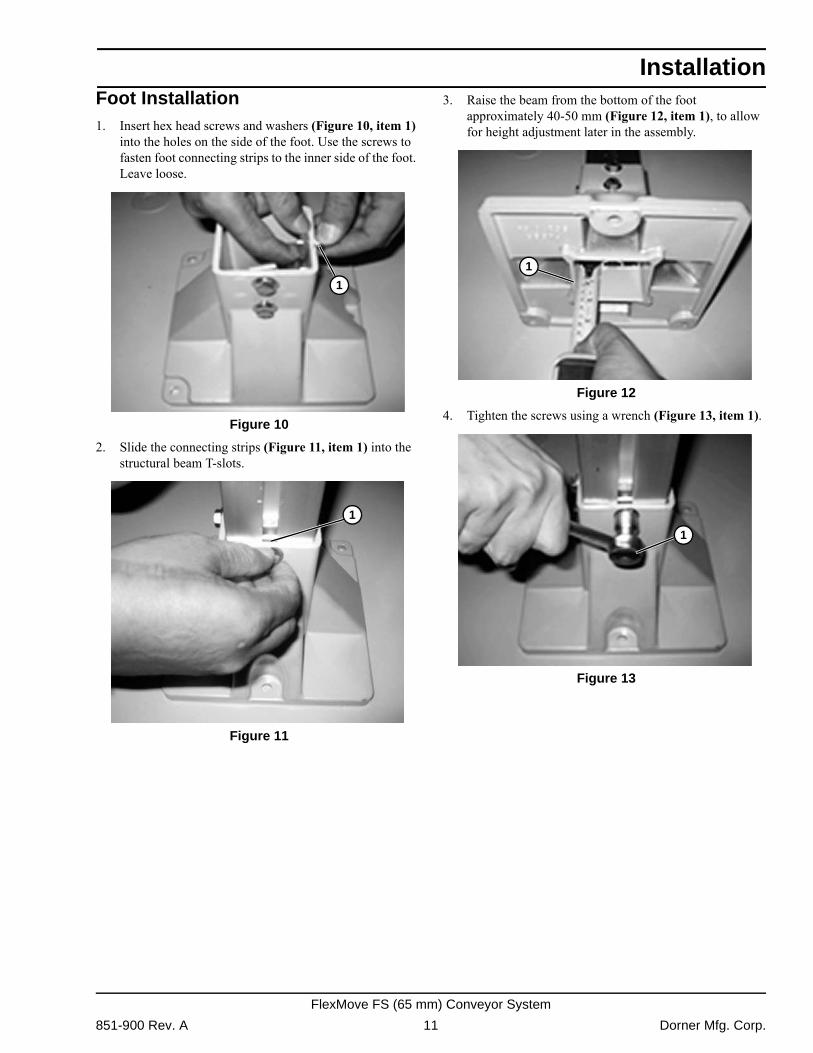
Spring nuts (Figure 5) can be inserted into the T-slot of FlexMove conveyors and support beams. They do not stay in place in vertical positions.
Figure 5
Figure 5
Connecting Strip
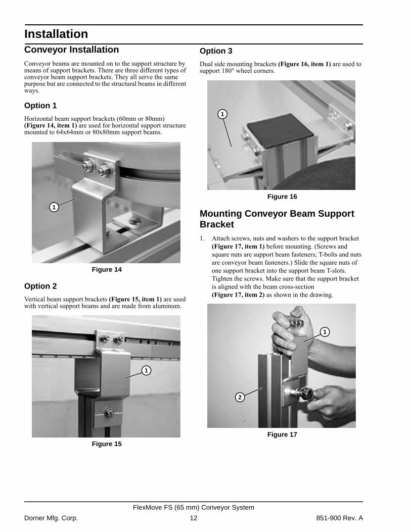
Connecting strips (Figure 6) are used for joining end to end of beams. Use hex key and set screws when attaching the connecting strip to the beam.
Figure 6
Figure 6
851-900 Rev. A 9 Dorner Mfg. Corp.
FlexMove FS (65 mm) Conveyor System
Installation
T-BoltT-bolts (Figure 7) can be entered from the beam side, and when turned 90 degrees they will stay in place after tightening with lock nuts. Use lock nuts to facilitate T-bolt turning in slot. The indication groove in the T-bolt should be at 90 degrees to the conveyor T-slot. T-bolts are used when attaching support brackets, guide rails and drip trays to the conveyor beam. T-bolts should not be used when fine adjustment for exact positioning is required (use square nuts or spring nuts for this type of application). Do not use T-bolts with support beams.
Figure 7
Figure 7
Pre installation Information
Cutting FlexMove Beam
Cutting is required for all 3m beams, including a precise cut to 3m lengths. Study your drawing to determine the beam lengths required before cutting.
Saw Requirements
The circular cross-cut saw used for aluminum profile cutting must be equipped with carbide tip saw circulating at high speed for a clean cut. The saw should have the ability of cutting the largest profile in one single cutting action.
Working Site
You should use a special area for cutting beams in order to keep the assembly area clean.
Quality of Cut
If burrs are evident, they must be removed prior to assembly. Make sure the cut is straight for proper assembly.
Assembly
The basic FlexMove conveyor structure consists of five component groups (See (Figure 8) and (Figure 9)):
Figure 8
Figure 8 Figure 9
Figure 9
� Support structure� Conveyor beams, straight sections, and bends� Drive and idler units� Chains� Guide rail assembly components� Other accessoriesThe first step in the assembly process is to assemble the support structure, which consists of feet, support beams, and beam support brackets. Most conveyor support designs are based on vertical support beams, combined, if necessary, with horizontal support beams. There are also a number of different feet and beam support brackets, so check which ones are suitable to use in your application.
A WARNINGAll safety precautions issued by the cutting saw manufacturer should be followed at all the times.
Dorner Mfg. Corp. 10 851-900 Rev. A
FlexMove FS (65 mm) Conveyor System
Installation
Foot Installation1. Insert hex head screws and washers (Figure 10, item 1)into the holes on the side of the foot. Use the screws to fasten foot connecting strips to the inner side of the foot. Leave loose.
Figure 10
Figure 10
2. Slide the connecting strips (Figure 11, item 1) into the structural beam T-slots.
Figure 11
Figure 11
3. Raise the beam from the bottom of the foot approximately 40-50 mm (Figure 12, item 1), to allow for height adjustment later in the assembly.
Figure 12
Figure 12
4. Tighten the screws using a wrench (Figure 13, item 1). Figure 13
Figure 13
1
1
1
1
851-900 Rev. A 11 Dorner Mfg. Corp.
FlexMove FS (65 mm) Conveyor System
Installation
Conveyor InstallationConveyor beams are mounted on to the support structure by means of support brackets. There are three different types of conveyor beam support brackets. They all serve the same purpose but are connected to the structural beams in different ways.Option 1
Horizontal beam support brackets (60mm or 80mm) (Figure 14, item 1) are used for horizontal support structure mounted to 64x64mm or 80x80mm support beams.
Figure 14
Figure 14
Option 2
Vertical beam support brackets (Figure 15, item 1) are used with vertical support beams and are made from aluminum.
Figure 15
Figure 15
Option 3
Dual side mounting brackets (Figure 16, item 1) are used to support 180° wheel corners.
Figure 16
Figure 16
Mounting Conveyor Beam Support Bracket1. Attach screws, nuts and washers to the support bracket
(Figure 17, item 1) before mounting. (Screws and square nuts are support beam fasteners; T-bolts and nuts are conveyor beam fasteners.) Slide the square nuts of one support bracket into the support beam T-slots. Tighten the screws. Make sure that the support bracket is aligned with the beam cross-section (Figure 17, item 2) as shown in the drawing.
Figure 17
Figure 17
1
1
1
1
2
Dorner Mfg. Corp. 12 851-900 Rev. A
FlexMove FS (65 mm) Conveyor System
Installation
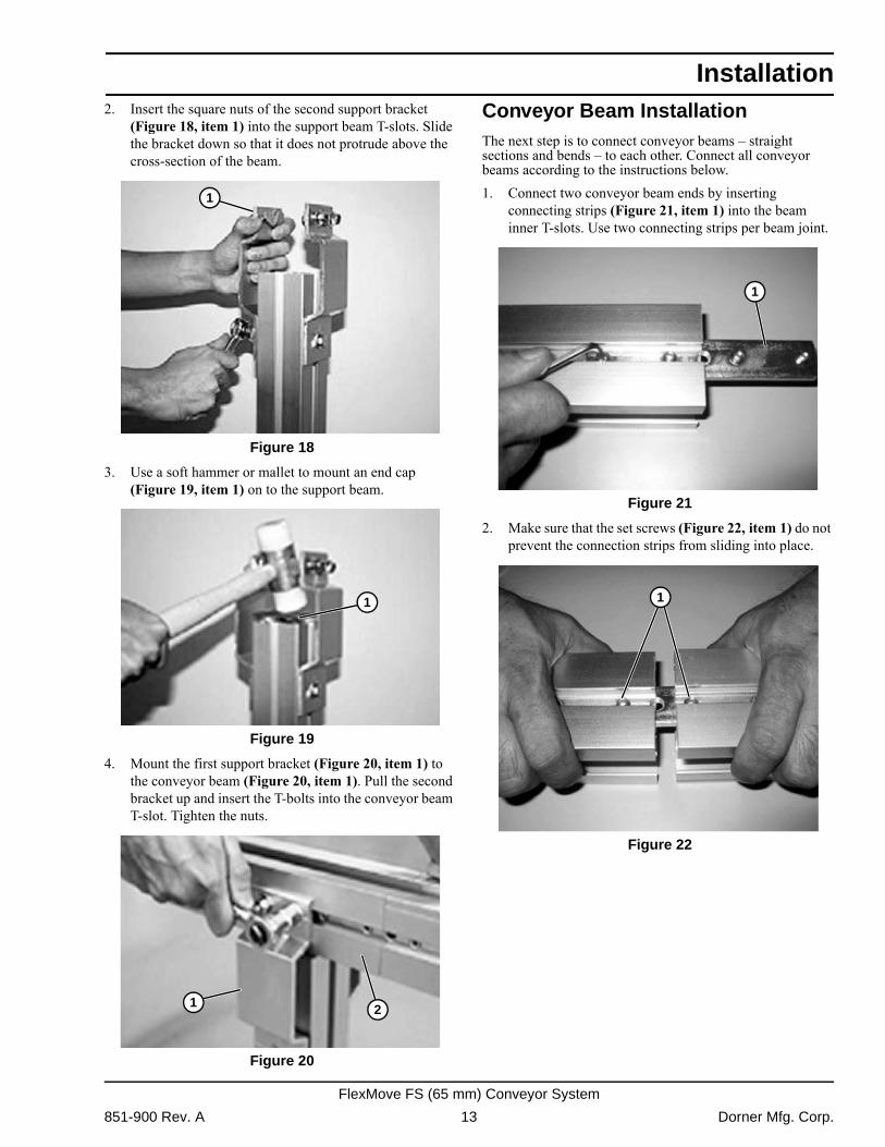
2. Insert the square nuts of the second support bracket(Figure 18, item 1) into the support beam T-slots. Slide the bracket down so that it does not protrude above the cross-section of the beam.
Figure 18
Figure 18
3. Use a soft hammer or mallet to mount an end cap (Figure 19, item 1) on to the support beam.
Figure 19
Figure 19
4. Mount the first support bracket (Figure 20, item 1) to the conveyor beam (Figure 20, item 1). Pull the second bracket up and insert the T-bolts into the conveyor beam T-slot. Tighten the nuts.
Figure 20
Figure 20
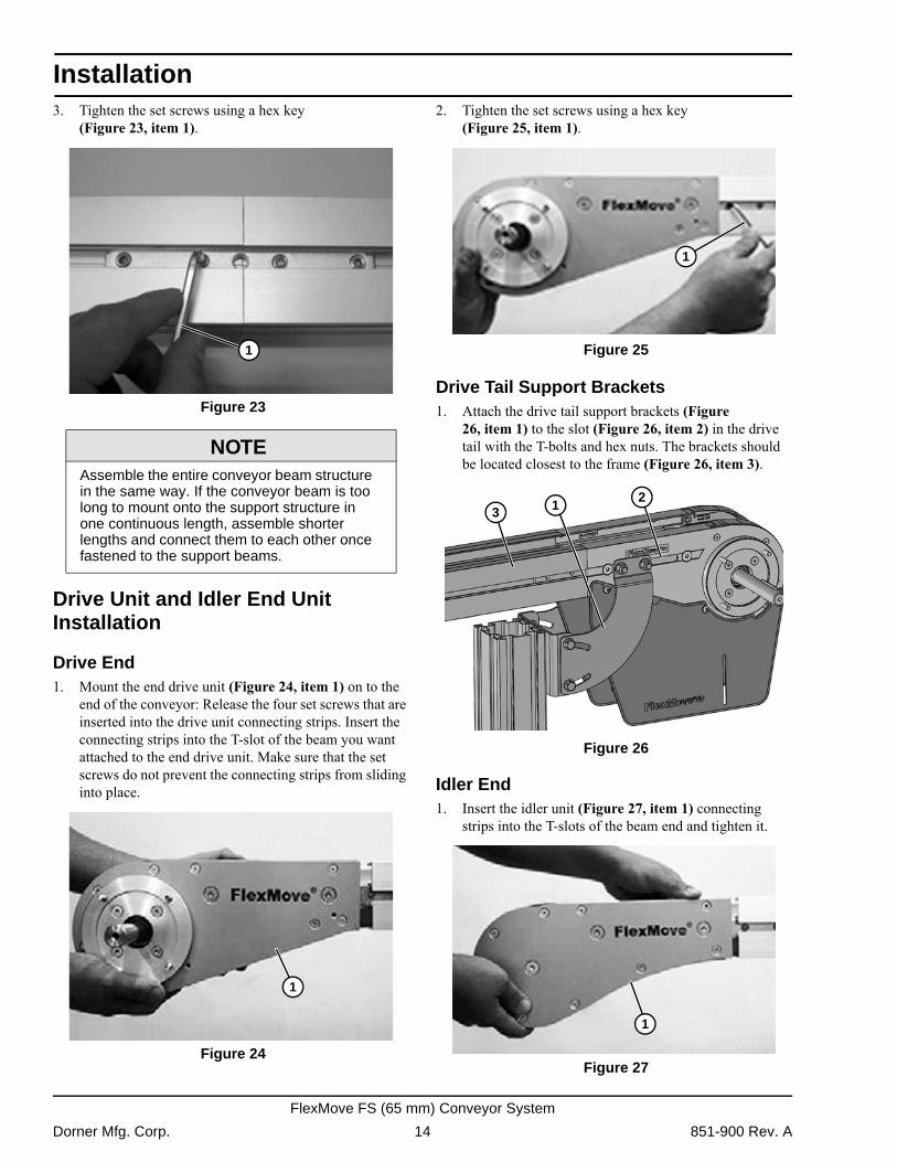
Conveyor Beam InstallationThe next step is to connect conveyor beams � straight sections and bends � to each other. Connect all conveyor beams according to the instructions below.1. Connect two conveyor beam ends by inserting
connecting strips (Figure 21, item 1) into the beam inner T-slots. Use two connecting strips per beam joint.
Figure 21
Figure 21
2. Make sure that the set screws (Figure 22, item 1) do not prevent the connection strips from sliding into place.
Figure 22
Figure 22
1
1
1 2
1
1
851-900 Rev. A 13 Dorner Mfg. Corp.
FlexMove FS (65 mm) Conveyor System
Installation
3. Tighten the set screws using a hex key(Figure 23, item 1). Figure 23
Figure 23
Drive Unit and Idler End Unit Installation
Drive End1. Mount the end drive unit (Figure 24, item 1) on to the
end of the conveyor: Release the four set screws that are inserted into the drive unit connecting strips. Insert the connecting strips into the T-slot of the beam you want attached to the end drive unit. Make sure that the set screws do not prevent the connecting strips from sliding into place.
Figure 24
Figure 24
2. Tighten the set screws using a hex key (Figure 25, item 1).
Figure 25
Figure 25
Drive Tail Support Brackets1. Attach the drive tail support brackets (Figure
26, item 1) to the slot (Figure 26, item 2) in the drive tail with the T-bolts and hex nuts. The brackets should be located closest to the frame (Figure 26, item 3).
Figure 26
Figure 26
Idler End1. Insert the idler unit (Figure 27, item 1) connecting
strips into the T-slots of the beam end and tighten it. Figure 27
Figure 27
NOTEAssemble the entire conveyor beam structure in the same way. If the conveyor beam is too long to mount onto the support structure in one continuous length, assemble shorter lengths and connect them to each other once fastened to the support beams.
1
1
1
213
1
Dorner Mfg. Corp. 14 851-900 Rev. A
FlexMove FS (65 mm) Conveyor System
Installation
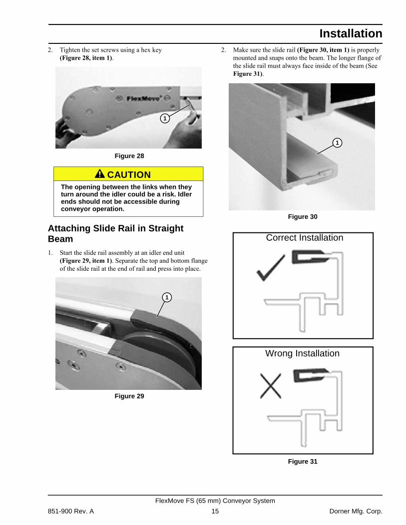
2. Tighten the set screws using a hex key(Figure 28, item 1). Figure 28
Figure 28
Attaching Slide Rail in Straight Beam1. Start the slide rail assembly at an idler end unit
(Figure 29, item 1). Separate the top and bottom flange of the slide rail at the end of rail and press into place.
Figure 29
Figure 29
2. Make sure the slide rail (Figure 30, item 1) is properly mounted and snaps onto the beam. The longer flange of the slide rail must always face inside of the beam (See Figure 31).
Figure 30
Figure 30 Figure 31
Figure 31
A CAUTIONThe opening between the links when they turn around the idler could be a risk. Idler ends should not be accessible during conveyor operation.
1
1
1
1
Correct Installation
Wrong Installation
851-900 Rev. A 15 Dorner Mfg. Corp.
FlexMove FS (65 mm) Conveyor System
Installation
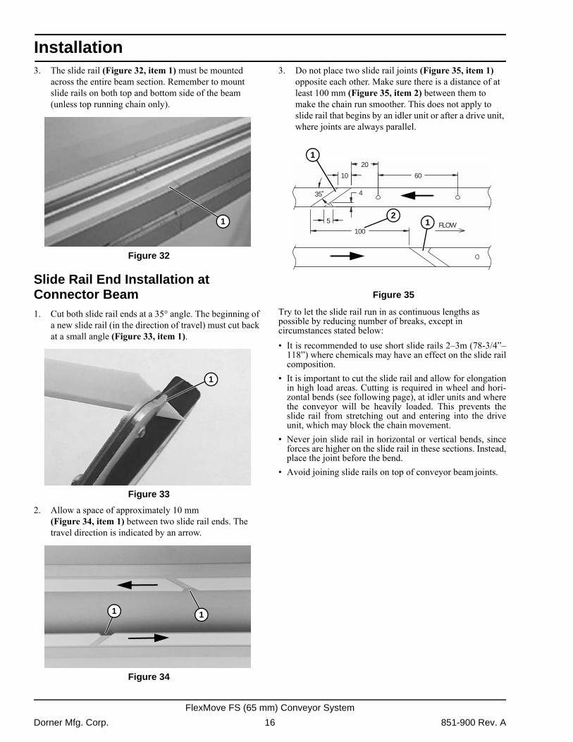
3. The slide rail (Figure 32, item 1) must be mountedacross the entire beam section. Remember to mount slide rails on both top and bottom side of the beam (unless top running chain only).
Figure 32
Figure 32
Slide Rail End Installation at Connector Beam1. Cut both slide rail ends at a 35° angle. The beginning of
a new slide rail (in the direction of travel) must cut back at a small angle (Figure 33, item 1).
Figure 33
Figure 33
2. Allow a space of approximately 10 mm (Figure 34, item 1) between two slide rail ends. The travel direction is indicated by an arrow.
Figure 34
Figure 34
3. Do not place two slide rail joints (Figure 35, item 1) opposite each other. Make sure there is a distance of at least 100 mm (Figure 35, item 2) between them to make the chain run smoother. This does not apply to slide rail that begins by an idler unit or after a drive unit, where joints are always parallel.
Figure 35
Figure 35
Try to let the slide rail run in as continuous lengths as possible by reducing number of breaks, except in circumstances stated below:� It is recommended to use short slide rails 2�3m (78-3/4��
118�) where chemicals may have an effect on the slide railcomposition.
� It is important to cut the slide rail and allow for elongationin high load areas. Cutting is required in wheel and hori-zontal bends (see following page), at idler units and wherethe conveyor will be heavily loaded. This prevents theslide rail from stretching out and entering into the driveunit, which may block the chain movement.
� Never join slide rail in horizontal or vertical bends, sinceforces are higher on the slide rail in these sections. Instead,place the joint before the bend.
� Avoid joining slide rails on top of conveyor beam joints.
1
1
1 1
FLOW
10
20
60
35˚
5
4
100
21
1
Dorner Mfg. Corp. 16 851-900 Rev. A
FlexMove FS (65 mm) Conveyor System
Installation
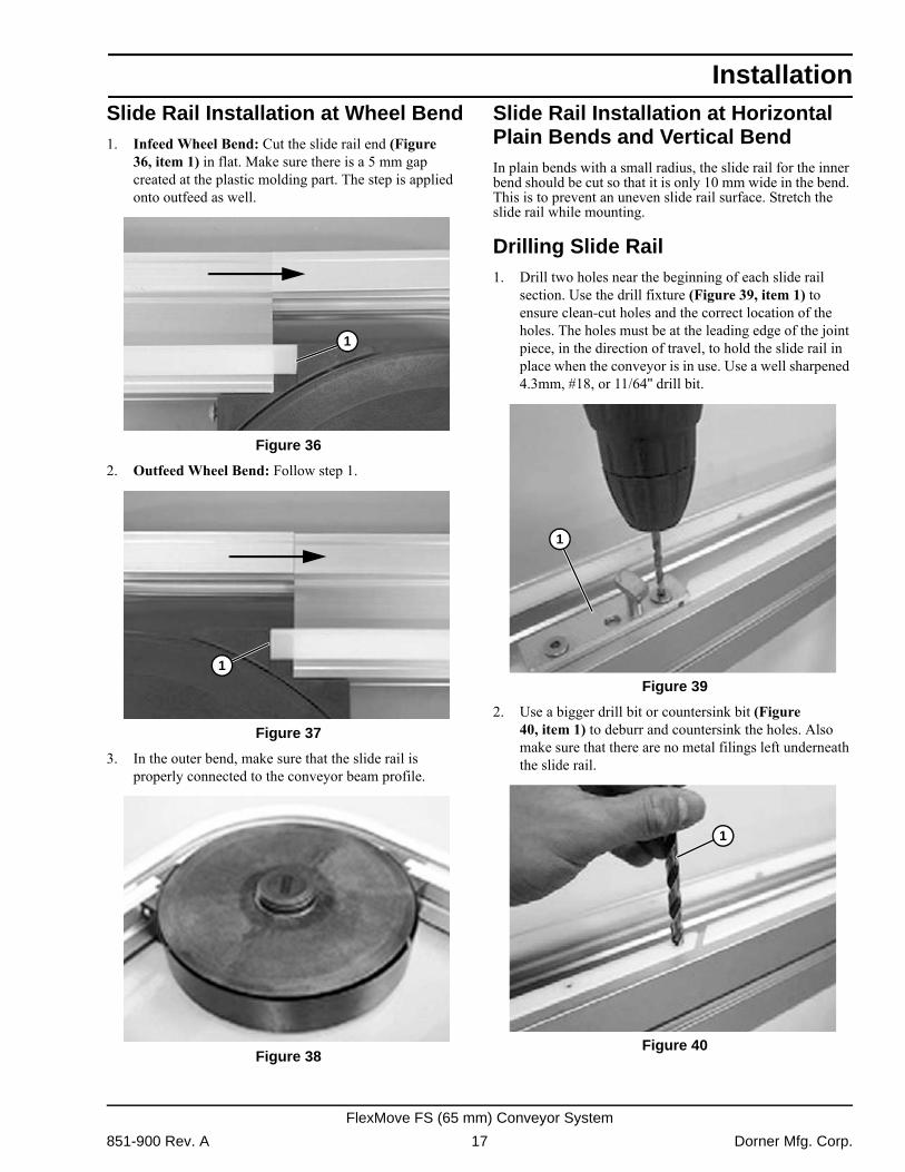
Slide Rail Installation at Wheel Bend1. Infeed Wheel Bend: Cut the slide rail end (Figure36, item 1) in flat. Make sure there is a 5 mm gap created at the plastic molding part. The step is applied onto outfeed as well.
Figure 36
Figure 36
2. Outfeed Wheel Bend: Follow step 1. Figure 37
Figure 37
3. In the outer bend, make sure that the slide rail is properly connected to the conveyor beam profile.
Figure 38
Figure 38
Slide Rail Installation at Horizontal Plain Bends and Vertical BendIn plain bends with a small radius, the slide rail for the inner bend should be cut so that it is only 10 mm wide in the bend. This is to prevent an uneven slide rail surface. Stretch the slide rail while mounting.
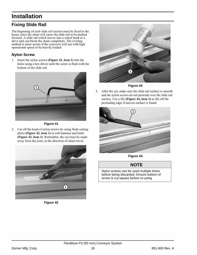
Drilling Slide Rail1. Drill two holes near the beginning of each slide rail
section. Use the drill fixture (Figure 39, item 1) to ensure clean-cut holes and the correct location of the holes. The holes must be at the leading edge of the joint piece, in the direction of travel, to hold the slide rail in place when the conveyor is in use. Use a well sharpened 4.3mm, #18, or 11/64" drill bit.
Figure 39
Figure 39
2. Use a bigger drill bit or countersink bit (Figure 40, item 1) to deburr and countersink the holes. Also make sure that there are no metal filings left underneath the slide rail.
Figure 40
Figure 40
1
1
1
1
1
851-900 Rev. A 17 Dorner Mfg. Corp.
FlexMove FS (65 mm) Conveyor System
Installation
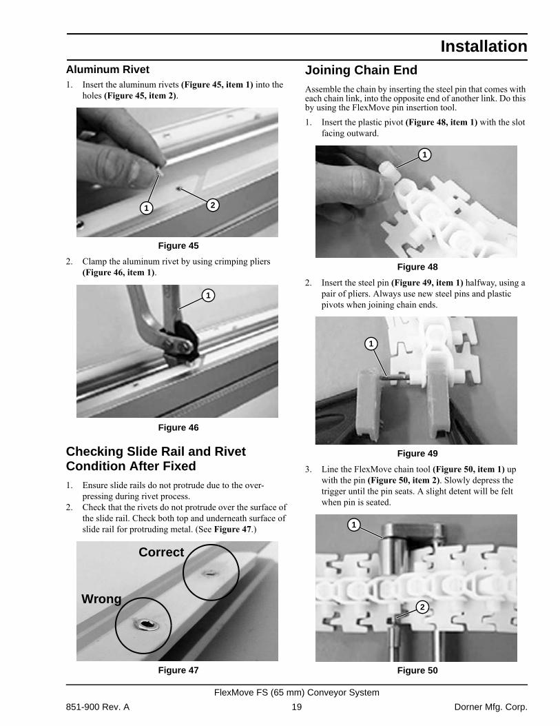
Fixing Slide RailThe beginning of each slide rail section must be fixed to the beam, since the chain will cause the slide rail to be pushed forward. A slide rail which moves into a wheel bend or a drive unit can block the chain completely. The riveting method is more secure if the conveyor will run with high operational speed or be heavily loaded.Nylon Screw1. Insert the nylon screws (Figure 41, item 1) into the
holes using a hex driver until the screw is flush with the bottom of the slide rail.
Figure 41
Figure 41
2. Cut off the head of nylon screws by using flush cutting pliers (Figure 42, item 1) or soft hammer and knife (Figure 43, item 1). Remember, the cut must be made away from the joint, in the direction of chain travel.
Figure 42
Figure 42
Figure 43
Figure 43
3. After the cut, make sure the slide rail surface is smooth and the nylon screws do not protrude over the slide rail surface. Use a file (Figure 44, item 1) to file off the protruding edge if uneven surface is found.
Figure 44
Figure 44
1
1
NOTENylon screws can be used multiple times before being discarded. Ensure bottom of screw is cut square before re-using.
1
1
Dorner Mfg. Corp. 18 851-900 Rev. A
FlexMove FS (65 mm) Conveyor System
Installation
Aluminum Rivet1. Insert the aluminum rivets (Figure 45, item 1) into theholes (Figure 45, item 2). Figure 45
Figure 45
2. Clamp the aluminum rivet by using crimping pliers (Figure 46, item 1).
Figure 46
Figure 46
Checking Slide Rail and Rivet Condition After Fixed1. Ensure slide rails do not protrude due to the over-
pressing during rivet process.2. Check that the rivets do not protrude over the surface of
the slide rail. Check both top and underneath surface of slide rail for protruding metal. (See Figure 47.)
Figure 47
Figure 47
Joining Chain EndAssemble the chain by inserting the steel pin that comes with each chain link, into the opposite end of another link. Do this by using the FlexMove pin insertion tool.1. Insert the plastic pivot (Figure 48, item 1) with the slot
facing outward. Figure 48
Figure 48
2. Insert the steel pin (Figure 49, item 1) halfway, using a pair of pliers. Always use new steel pins and plastic pivots when joining chain ends.
Figure 49
Figure 49
3. Line the FlexMove chain tool (Figure 50, item 1) up with the pin (Figure 50, item 2). Slowly depress the trigger until the pin seats. A slight detent will be felt when pin is seated.
Figure 50
Figure 50
1 2
1
Correct
Wrong
1
1
1
2
851-900 Rev. A 19 Dorner Mfg. Corp.
FlexMove FS (65 mm) Conveyor System
Installation
4. Check that the chain is flexible in the joint and that thepin does not stick out or go through the other side (Figure 51, item 1).
Figure 51
Figure 51
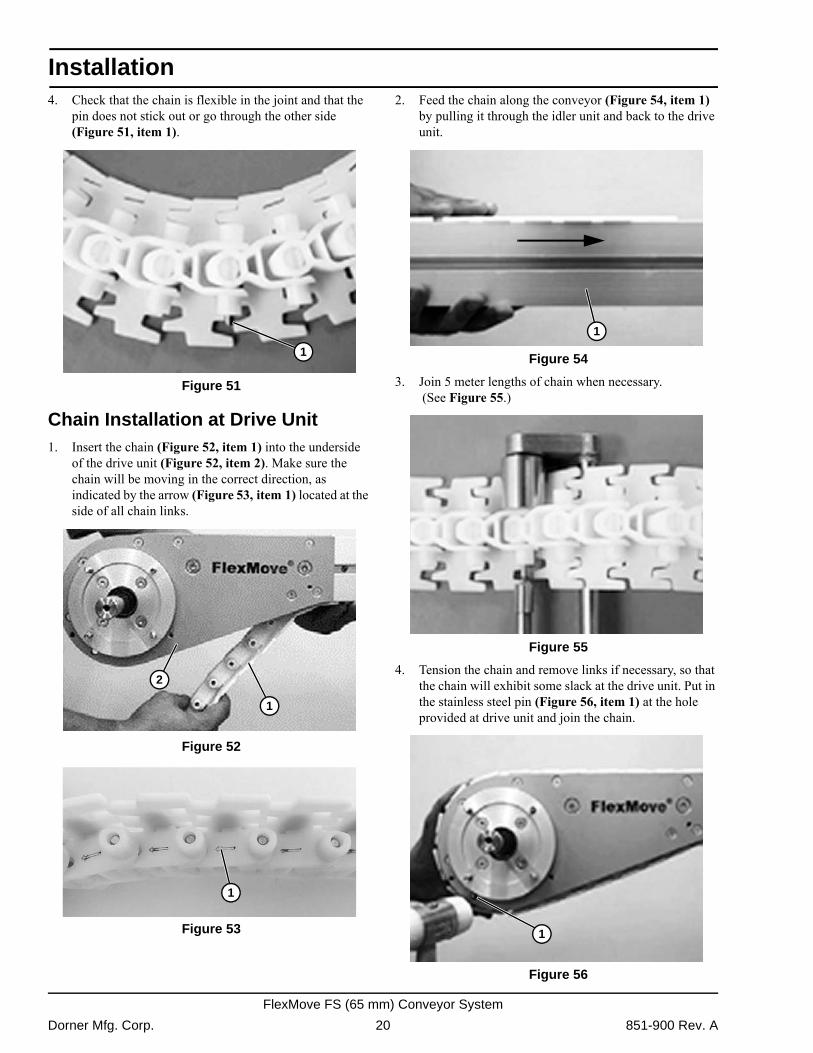
Chain Installation at Drive Unit1. Insert the chain (Figure 52, item 1) into the underside
of the drive unit (Figure 52, item 2). Make sure the chain will be moving in the correct direction, as indicated by the arrow (Figure 53, item 1) located at the side of all chain links.
Figure 52
Figure 52 Figure 53
Figure 53
2. Feed the chain along the conveyor (Figure 54, item 1) by pulling it through the idler unit and back to the drive unit.
Figure 54
Figure 54
3. Join 5 meter lengths of chain when necessary. (See Figure 55.)
Figure 55
Figure 55
4. Tension the chain and remove links if necessary, so that the chain will exhibit some slack at the drive unit. Put in the stainless steel pin (Figure 56, item 1) at the hole provided at drive unit and join the chain.
Figure 56
Figure 56
1
1
2
1
1
1
Dorner Mfg. Corp. 20 851-900 Rev. A
FlexMove FS (65 mm) Conveyor System
Installation
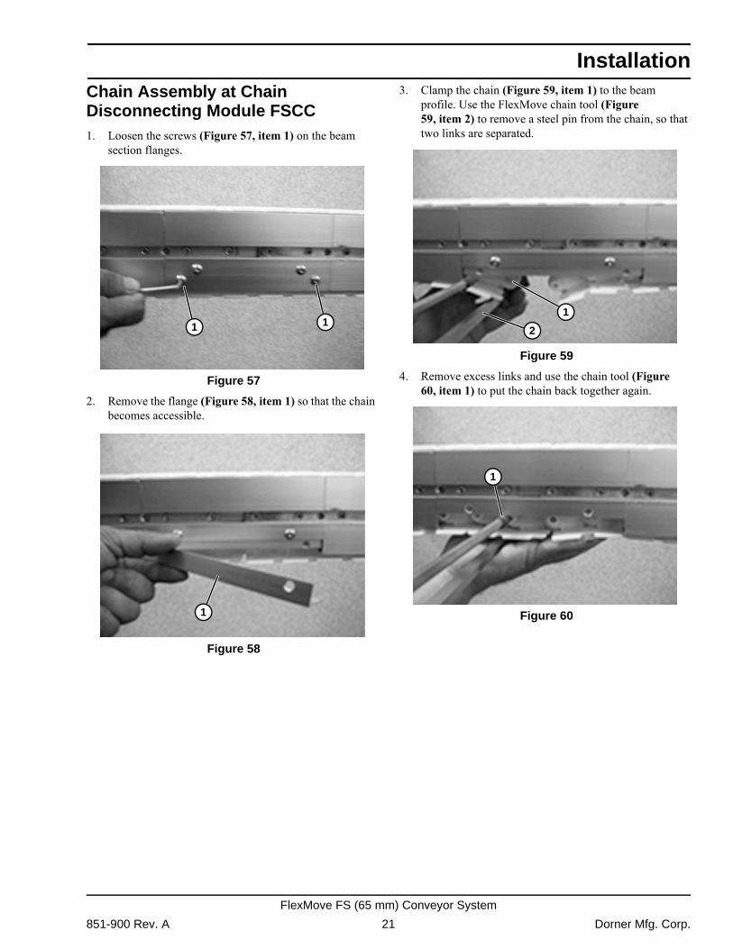
Chain Assembly at Chain Disconnecting Module FSCC1. Loosen the screws (Figure 57, item 1) on the beamsection flanges. Figure 57
Figure 57
2. Remove the flange (Figure 58, item 1) so that the chain becomes accessible.
Figure 58
Figure 58
3. Clamp the chain (Figure 59, item 1) to the beam profile. Use the FlexMove chain tool (Figure 59, item 2) to remove a steel pin from the chain, so that two links are separated.
Figure 59
Figure 59
4. Remove excess links and use the chain tool (Figure 60, item 1) to put the chain back together again.
Figure 60
Figure 60
1 1
1
1
2
1
851-900 Rev. A 21 Dorner Mfg. Corp.
FlexMove FS (65 mm) Conveyor System
Installation
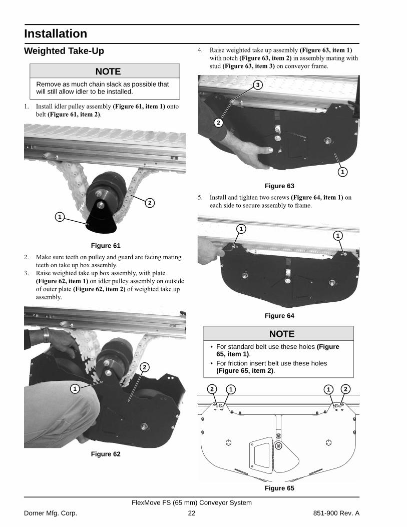
Weighted Take-Up1. Install idler pulley assembly (Figure 61, item 1) onto belt (Figure 61, item 2).
Figure 61
Figure 61
2. Make sure teeth on pulley and guard are facing mating teeth on take up box assembly.
3. Raise weighted take up box assembly, with plate (Figure 62, item 1) on idler pulley assembly on outside of outer plate (Figure 62, item 2) of weighted take up assembly.
Figure 62
Figure 62
4. Raise weighted take up assembly (Figure 63, item 1) with notch (Figure 63, item 2) in assembly mating with stud (Figure 63, item 3) on conveyor frame.
Figure 63
Figure 63
5. Install and tighten two screws (Figure 64, item 1) on each side to secure assembly to frame.
Figure 64
Figure 64
Figure 65
Figure 65
NOTERemove as much chain slack as possible that will still allow idler to be installed.
2
1
1
2
NOTE• For standard belt use these holes (Figure
65, item 1).• For friction insert belt use these holes
(Figure 65, item 2).
2
3
1
11
1 1 22
Dorner Mfg. Corp. 22 851-900 Rev. A
FlexMove FS (65 mm) Conveyor System
Installation
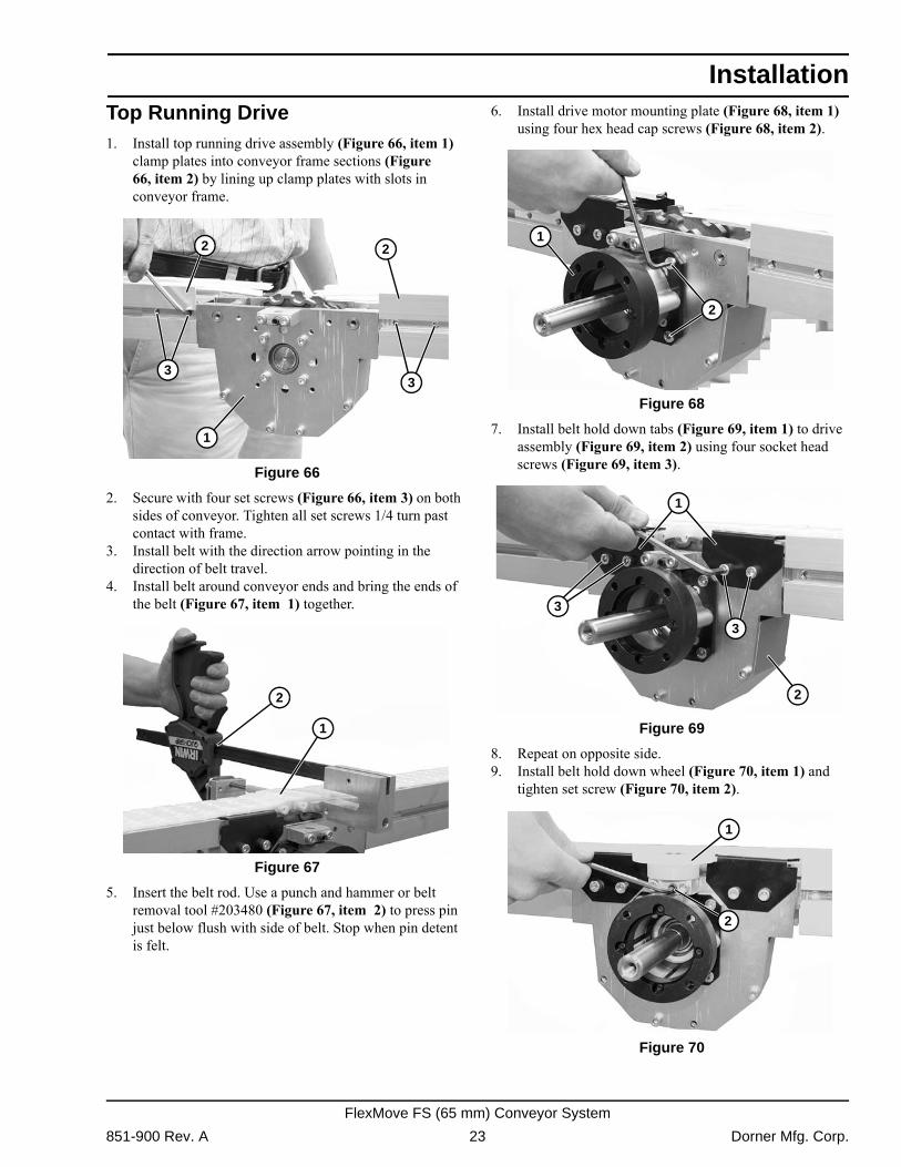
Top Running Drive1. Install top running drive assembly (Figure 66, item 1)clamp plates into conveyor frame sections (Figure 66, item 2) by lining up clamp plates with slots in conveyor frame.
Figure 66
Figure 66
2. Secure with four set screws (Figure 66, item 3) on both sides of conveyor. Tighten all set screws 1/4 turn past contact with frame.
3. Install belt with the direction arrow pointing in the direction of belt travel.
4. Install belt around conveyor ends and bring the ends of the belt (Figure 67, item 1) together.
Figure 67
Figure 67
5. Insert the belt rod. Use a punch and hammer or belt removal tool #203480 (Figure 67, item 2) to press pin just below flush with side of belt. Stop when pin detent is felt.
6. Install drive motor mounting plate (Figure 68, item 1) using four hex head cap screws (Figure 68, item 2).
Figure 68
Figure 68
7. Install belt hold down tabs (Figure 69, item 1) to drive assembly (Figure 69, item 2) using four socket head screws (Figure 69, item 3).
Figure 69
Figure 69
8. Repeat on opposite side.9. Install belt hold down wheel (Figure 70, item 1) and
tighten set screw (Figure 70, item 2). Figure 70
Figure 70
1
33
22
1
2
1
2
3
3
2
1
1
2
851-900 Rev. A 23 Dorner Mfg. Corp.
FlexMove FS (65 mm) Conveyor System
Installation
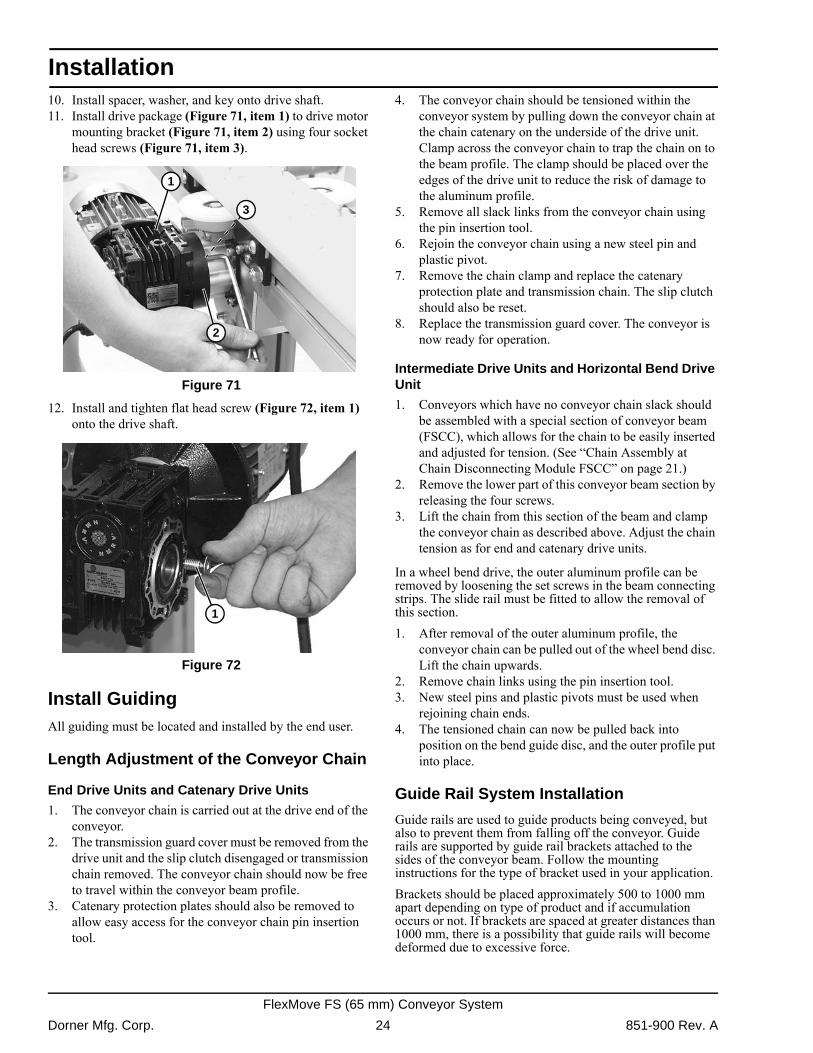
10. Install spacer, washer, and key onto drive shaft.11. Install drive package (Figure 71, item 1) to drive motormounting bracket (Figure 71, item 2) using four socket head screws (Figure 71, item 3).
Figure 71
Figure 71
12. Install and tighten flat head screw (Figure 72, item 1) onto the drive shaft.
Figure 72
Figure 72
Install GuidingAll guiding must be located and installed by the end user.
Length Adjustment of the Conveyor Chain
End Drive Units and Catenary Drive Units
1. The conveyor chain is carried out at the drive end of the conveyor.
2. The transmission guard cover must be removed from the drive unit and the slip clutch disengaged or transmission chain removed. The conveyor chain should now be free to travel within the conveyor beam profile.
3. Catenary protection plates should also be removed to allow easy access for the conveyor chain pin insertion tool.
4. The conveyor chain should be tensioned within the conveyor system by pulling down the conveyor chain at the chain catenary on the underside of the drive unit. Clamp across the conveyor chain to trap the chain on to the beam profile. The clamp should be placed over the edges of the drive unit to reduce the risk of damage to the aluminum profile.
5. Remove all slack links from the conveyor chain using the pin insertion tool.
6. Rejoin the conveyor chain using a new steel pin and plastic pivot.
7. Remove the chain clamp and replace the catenary protection plate and transmission chain. The slip clutch should also be reset.
8. Replace the transmission guard cover. The conveyor is now ready for operation.
Intermediate Drive Units and Horizontal Bend Drive Unit
1. Conveyors which have no conveyor chain slack should be assembled with a special section of conveyor beam (FSCC), which allows for the chain to be easily inserted and adjusted for tension. (See �Chain Assembly at Chain Disconnecting Module FSCC� on page 21.)
2. Remove the lower part of this conveyor beam section by releasing the four screws.
3. Lift the chain from this section of the beam and clamp the conveyor chain as described above. Adjust the chain tension as for end and catenary drive units.
In a wheel bend drive, the outer aluminum profile can be removed by loosening the set screws in the beam connecting strips. The slide rail must be fitted to allow the removal of this section.1. After removal of the outer aluminum profile, the
conveyor chain can be pulled out of the wheel bend disc. Lift the chain upwards.
2. Remove chain links using the pin insertion tool.3. New steel pins and plastic pivots must be used when
rejoining chain ends.4. The tensioned chain can now be pulled back into
position on the bend guide disc, and the outer profile put into place.
Guide Rail System Installation
Guide rails are used to guide products being conveyed, but also to prevent them from falling off the conveyor. Guide rails are supported by guide rail brackets attached to the sides of the conveyor beam. Follow the mounting instructions for the type of bracket used in your application.Brackets should be placed approximately 500 to 1000 mm apart depending on type of product and if accumulation occurs or not. If brackets are spaced at greater distances than 1000 mm, there is a possibility that guide rails will become deformed due to excessive force.
1
3
2
1
Dorner Mfg. Corp. 24 851-900 Rev. A
FlexMove FS (65 mm) Conveyor System
Installation
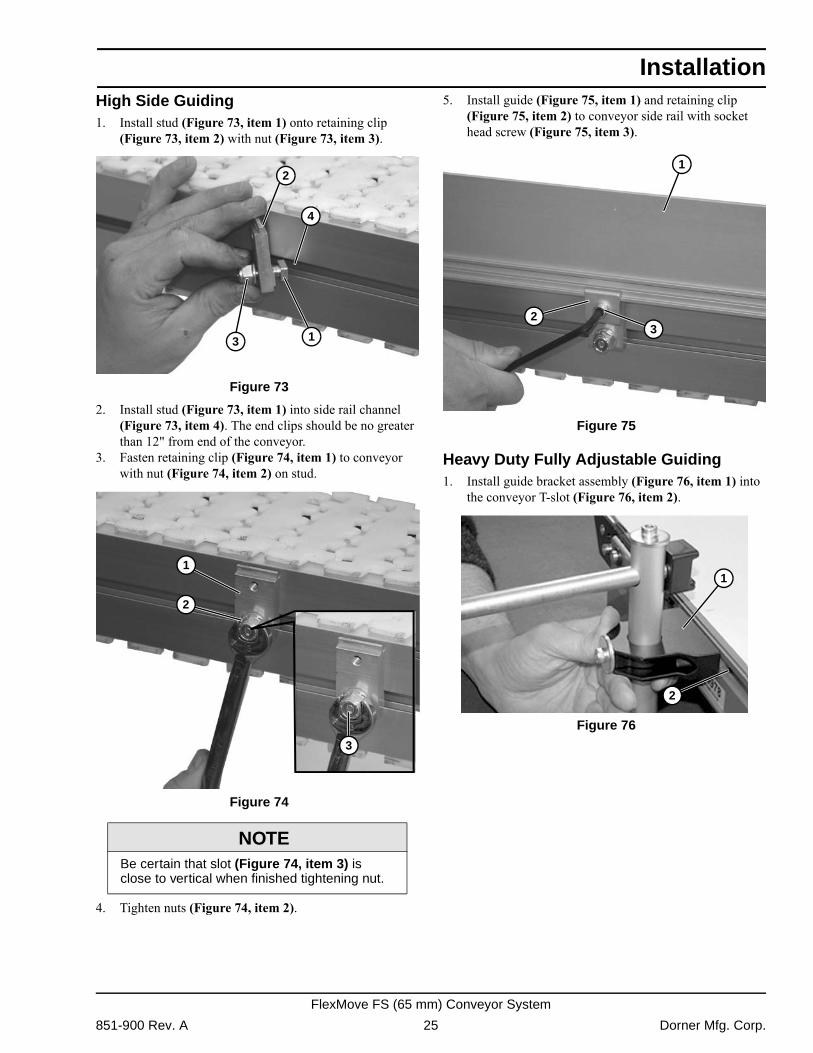
High Side Guiding1. Install stud (Figure 73, item 1) onto retaining clip(Figure 73, item 2) with nut (Figure 73, item 3). Figure 73
Figure 73
2. Install stud (Figure 73, item 1) into side rail channel (Figure 73, item 4). The end clips should be no greater than 12" from end of the conveyor.
3. Fasten retaining clip (Figure 74, item 1) to conveyor with nut (Figure 74, item 2) on stud.
Figure 74
Figure 74
4. Tighten nuts (Figure 74, item 2).
5. Install guide (Figure 75, item 1) and retaining clip (Figure 75, item 2) to conveyor side rail with socket head screw (Figure 75, item 3).
Figure 75
Figure 75
Heavy Duty Fully Adjustable Guiding1. Install guide bracket assembly (Figure 76, item 1) into
the conveyor T-slot (Figure 76, item 2). Figure 76
Figure 76
NOTEBe certain that slot (Figure 74, item 3) is close to vertical when finished tightening nut.
2
4
13
2
1
3
1
23
1
2
851-900 Rev. A 25 Dorner Mfg. Corp.
FlexMove FS (65 mm) Conveyor System
Installation
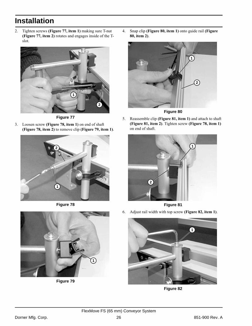
2. Tighten screws (Figure 77, item 1) making sure T-nut(Figure 77, item 2) rotates and engages inside of the T-slot.
Figure 77
Figure 77
3. Loosen screw (Figure 78, item 1) on end of shaft (Figure 78, item 2) to remove clip (Figure 79, item 1).
Figure 78
Figure 78 Figure 79
Figure 79
4. Snap clip (Figure 80, item 1) onto guide rail (Figure 80, item 2).
Figure 80
Figure 80
5. Reassemble clip (Figure 81, item 1) and attach to shaft (Figure 81, item 2). Tighten screw (Figure 78, item 1) on end of shaft.
Figure 81
Figure 81
6. Adjust rail width with top screw (Figure 82, item 1). Figure 82
Figure 82
1
2
1
2
1
1
2
1
2
1
Dorner Mfg. Corp. 26 851-900 Rev. A
FlexMove FS (65 mm) Conveyor System
Installation
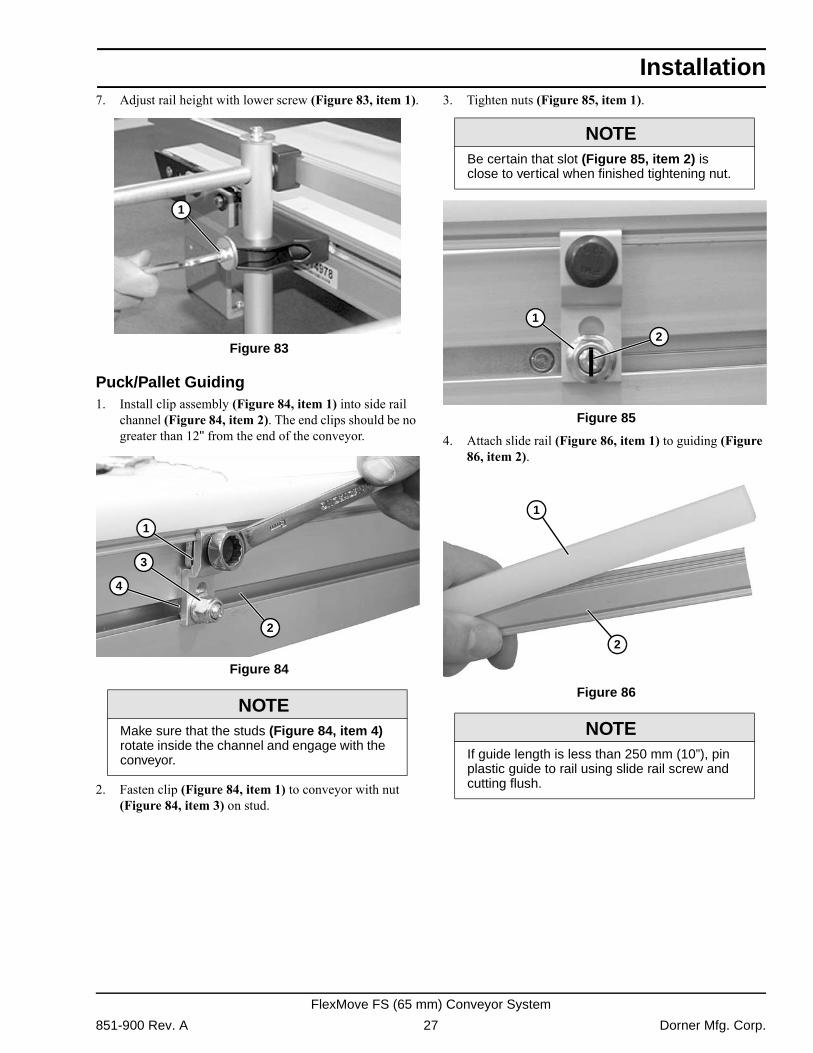
7. Adjust rail height with lower screw (Figure 83, item 1).Figure 83
Figure 83
Puck/Pallet Guiding1. Install clip assembly (Figure 84, item 1) into side rail
channel (Figure 84, item 2). The end clips should be no greater than 12" from the end of the conveyor.
Figure 84
Figure 84
2. Fasten clip (Figure 84, item 1) to conveyor with nut (Figure 84, item 3) on stud.
3. Tighten nuts (Figure 85, item 1).
Figure 85
Figure 85
4. Attach slide rail (Figure 86, item 1) to guiding (Figure 86, item 2).
Figure 86
Figure 86 NOTE
Make sure that the studs (Figure 84, item 4) rotate inside the channel and engage with the conveyor.
1
1
3
2
4
NOTEBe certain that slot (Figure 85, item 2) is close to vertical when finished tightening nut.
NOTEIf guide length is less than 250 mm (10”), pin plastic guide to rail using slide rail screw and cutting flush.
1
3
2
42
1
1
2
851-900 Rev. A 27 Dorner Mfg. Corp.
FlexMove FS (65 mm) Conveyor System
Installation
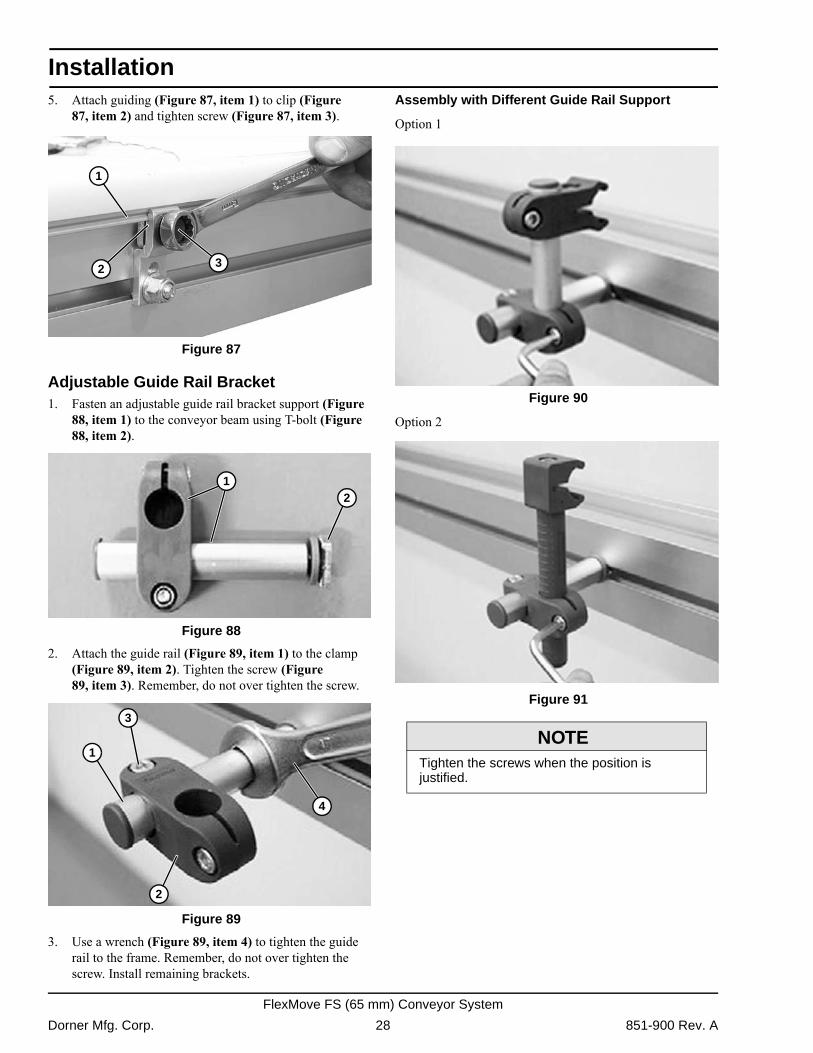
5. Attach guiding (Figure 87, item 1) to clip (Figure87, item 2) and tighten screw (Figure 87, item 3). Figure 87
Figure 87
Adjustable Guide Rail Bracket1. Fasten an adjustable guide rail bracket support (Figure
88, item 1) to the conveyor beam using T-bolt (Figure 88, item 2).
Figure 88
Figure 88
2. Attach the guide rail (Figure 89, item 1) to the clamp (Figure 89, item 2). Tighten the screw (Figure 89, item 3). Remember, do not over tighten the screw.
Figure 89
Figure 89
3. Use a wrench (Figure 89, item 4) to tighten the guide rail to the frame. Remember, do not over tighten the screw. Install remaining brackets.
Assembly with Different Guide Rail Support
Option 1 Figure 90
Figure 90
Option 2 Figure 91
Figure 91
1
32
21
4
2
1
3
NOTETighten the screws when the position is justified.
Dorner Mfg. Corp. 28 851-900 Rev. A
FlexMove FS (65 mm) Conveyor System
Installation
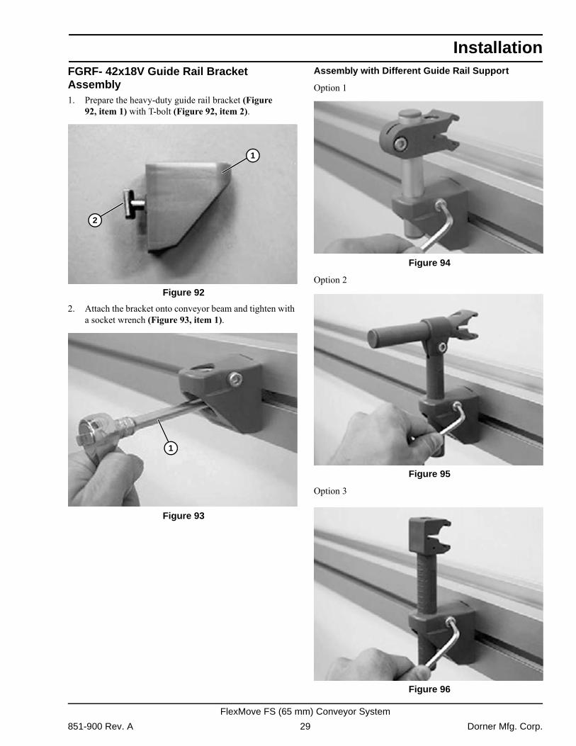
FGRF- 42x18V Guide Rail Bracket Assembly1. Prepare the heavy-duty guide rail bracket (Figure92, item 1) with T-bolt (Figure 92, item 2). Figure 92
Figure 92
2. Attach the bracket onto conveyor beam and tighten with a socket wrench (Figure 93, item 1).
Figure 93
Figure 93
Assembly with Different Guide Rail Support
Option 1 Figure 94
Figure 94
Option 2 Figure 95
Figure 95
Option 3 Figure 96
Figure 96
1
2
1
851-900 Rev. A 29 Dorner Mfg. Corp.
FlexMove FS (65 mm) Conveyor System
Installation
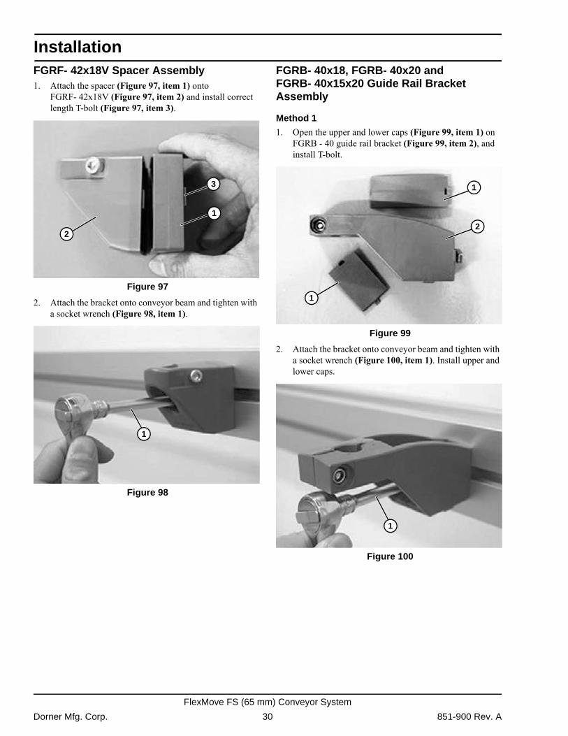
FGRF- 42x18V Spacer Assembly1. Attach the spacer (Figure 97, item 1) ontoFGRF- 42x18V (Figure 97, item 2) and install correct length T-bolt (Figure 97, item 3).
Figure 97
Figure 97
2. Attach the bracket onto conveyor beam and tighten with a socket wrench (Figure 98, item 1).
Figure 98
Figure 98
FGRB- 40x18, FGRB- 40x20 and FGRB- 40x15x20 Guide Rail Bracket Assembly
Method 1
1. Open the upper and lower caps (Figure 99, item 1) on FGRB - 40 guide rail bracket (Figure 99, item 2), and install T-bolt.
Figure 99
Figure 99
2. Attach the bracket onto conveyor beam and tighten with a socket wrench (Figure 100, item 1). Install upper and lower caps.
Figure 100
Figure 100
1
2
3
1
1
1
2
1
Dorner Mfg. Corp. 30 851-900 Rev. A
FlexMove FS (65 mm) Conveyor System
Installation
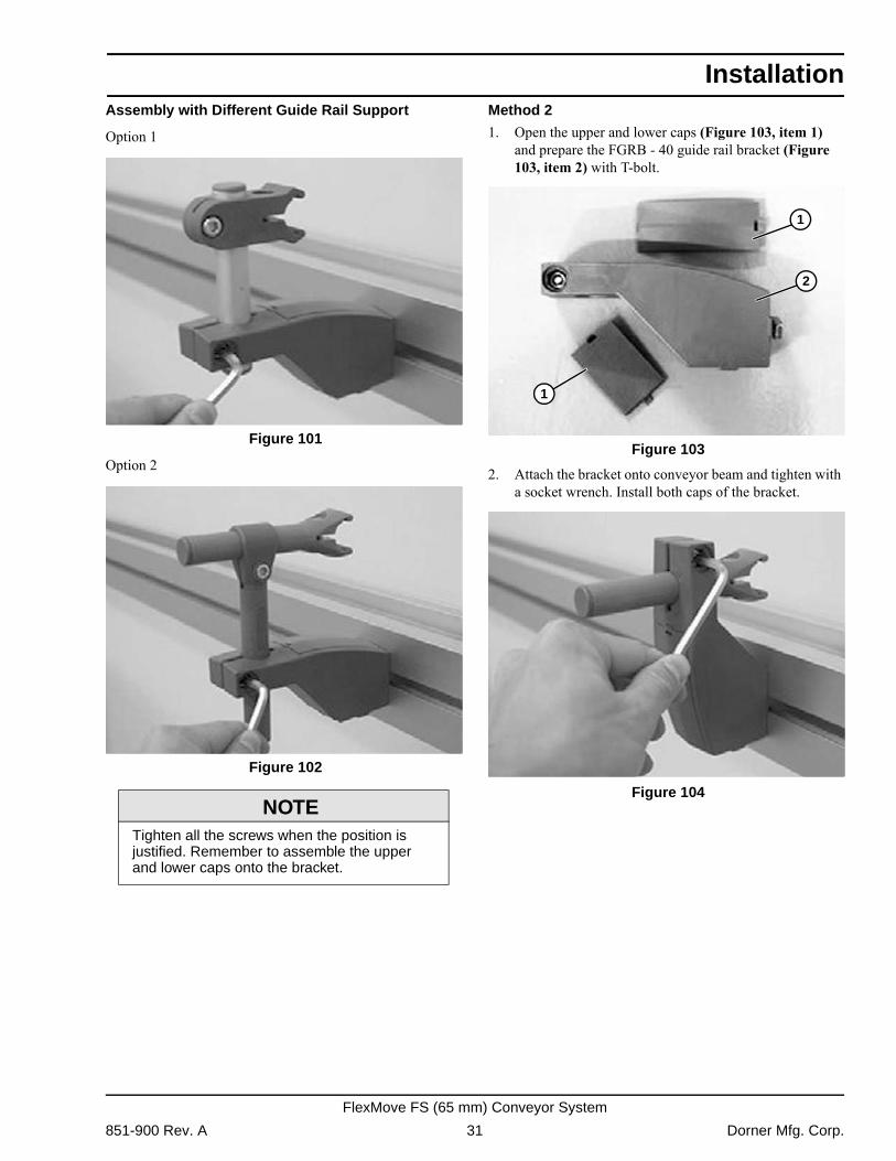
Assembly with Different Guide Rail SupportOption 1 Figure 101
Figure 101
Option 2 Figure 102
Figure 102
Method 2
1. Open the upper and lower caps (Figure 103, item 1) and prepare the FGRB - 40 guide rail bracket (Figure 103, item 2) with T-bolt.
Figure 103
Figure 103
2. Attach the bracket onto conveyor beam and tighten with a socket wrench. Install both caps of the bracket.
Figure 104
Figure 104 NOTE
Tighten all the screws when the position is justified. Remember to assemble the upper and lower caps onto the bracket.
1
1
2
1
1
2
851-900 Rev. A 31 Dorner Mfg. Corp.
FlexMove FS (65 mm) Conveyor System
Installation
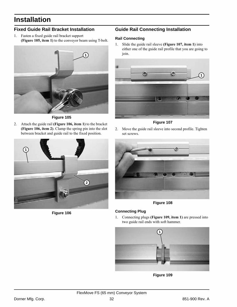
Fixed Guide Rail Bracket Installation1. Fasten a fixed guide rail bracket support(Figure 105, item 1) to the conveyor beam using T-bolt. Figure 105
Figure 105
2. Attach the guide rail (Figure 106, item 1) to the bracket (Figure 106, item 2). Clamp the spring pin into the slot between bracket and guide rail to the fixed position.
Figure 106
Figure 106
Guide Rail Connecting Installation
Rail Connecting
1. Slide the guide rail sleeve (Figure 107, item 1) into either one of the guide rail profile that you are going to join.
Figure 107
Figure 107
2. Move the guide rail sleeve into second profile. Tighten set screws.
Figure 108
Figure 108
Connecting Plug
1. Connecting plugs (Figure 109, item 1) are pressed into two guide rail ends with soft hammer.
Figure 109
Figure 109
1
1
2
1
1
Dorner Mfg. Corp. 32 851-900 Rev. A
FlexMove FS (65 mm) Conveyor System
Installation
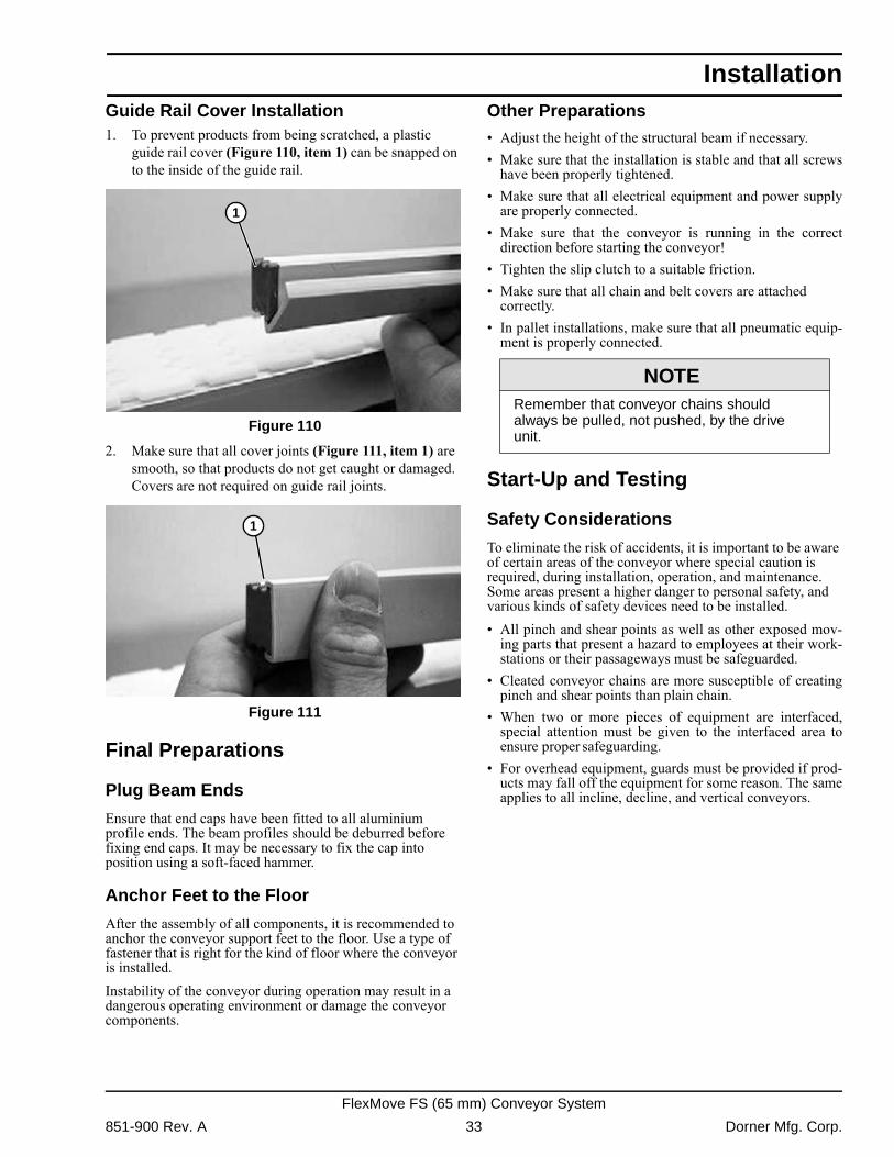
Guide Rail Cover Installation1. To prevent products from being scratched, a plasticguide rail cover (Figure 110, item 1) can be snapped on to the inside of the guide rail.
Figure 110
Figure 110
2. Make sure that all cover joints (Figure 111, item 1) are smooth, so that products do not get caught or damaged. Covers are not required on guide rail joints.
Figure 111
Figure 111
Final Preparations
Plug Beam Ends
Ensure that end caps have been fitted to all aluminium profile ends. The beam profiles should be deburred before fixing end caps. It may be necessary to fix the cap into position using a soft-faced hammer.
Anchor Feet to the Floor
After the assembly of all components, it is recommended to anchor the conveyor support feet to the floor. Use a type of fastener that is right for the kind of floor where the conveyor is installed.Instability of the conveyor during operation may result in a dangerous operating environment or damage the conveyor components.
Other Preparations� Adjust the height of the structural beam if necessary.� Make sure that the installation is stable and that all screws
have been properly tightened.� Make sure that all electrical equipment and power supply
are properly connected.� Make sure that the conveyor is running in the correct
direction before starting the conveyor!� Tighten the slip clutch to a suitable friction.� Make sure that all chain and belt covers are attached
correctly.� In pallet installations, make sure that all pneumatic equip-
ment is properly connected.
Start-Up and Testing
Safety Considerations
To eliminate the risk of accidents, it is important to be aware of certain areas of the conveyor where special caution is required, during installation, operation, and maintenance. Some areas present a higher danger to personal safety, and various kinds of safety devices need to be installed.� All pinch and shear points as well as other exposed mov-
ing parts that present a hazard to employees at their work-stations or their passageways must be safeguarded.
� Cleated conveyor chains are more susceptible of creatingpinch and shear points than plain chain.
� When two or more pieces of equipment are interfaced,special attention must be given to the interfaced area toensure proper safeguarding.
� For overhead equipment, guards must be provided if prod-ucts may fall off the equipment for some reason. The sameapplies to all incline, decline, and vertical conveyors.
1
1
NOTERemember that conveyor chains should always be pulled, not pushed, by the drive unit.
851-900 Rev. A 33 Dorner Mfg. Corp.
FlexMove FS (65 mm) Conveyor System
Installation
Safeguarding can be achieved by:� Location � locate the hazardous area out of reach of thepersonnel involved.� Guards � mechanical barriers preventing entry into the
hazardous area or protecting against falling goods. � Control devices � machine controls preventing or inter-
rupting hazardous conditions.� Warnings � instructions, warning labels, or sound or light
signals, alerting on hazardous conditions.� Warnings shall be used when other means of safeguarding
will impair the function of the installation.
Torque Limiter Adjustment for Suspended Drive Units
Introduction
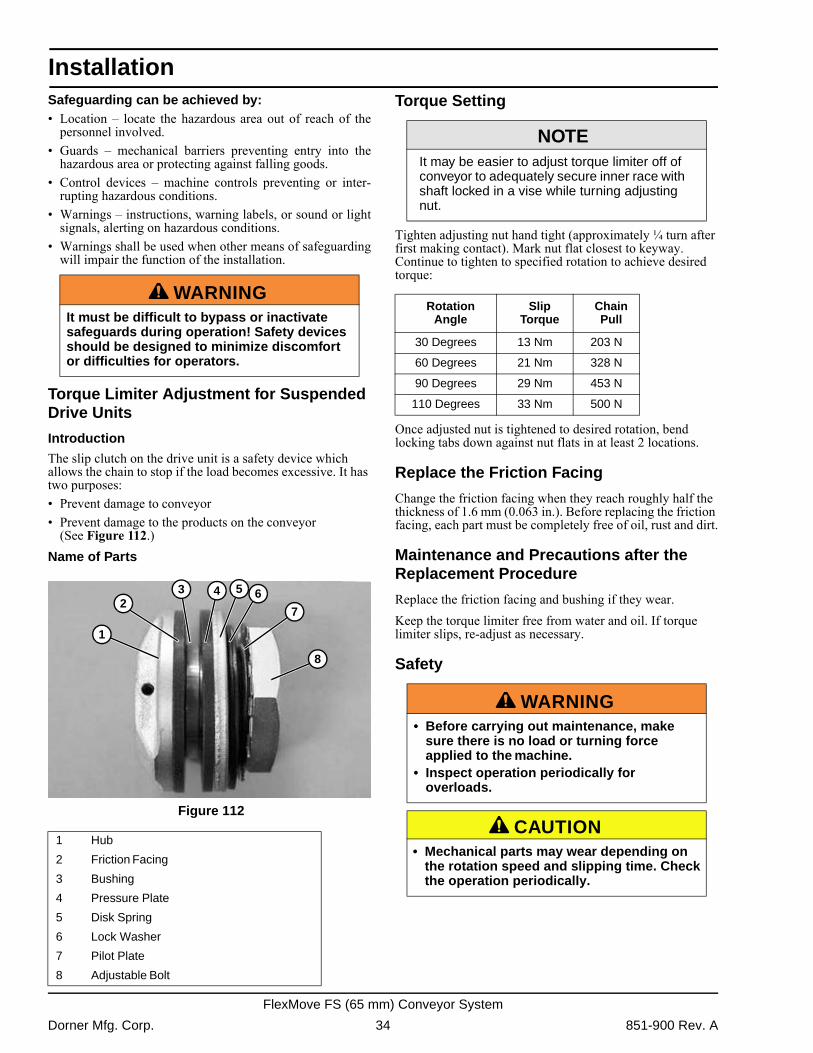
The slip clutch on the drive unit is a safety device which allows the chain to stop if the load becomes excessive. It has two purposes:� Prevent damage to conveyor� Prevent damage to the products on the conveyor
(See Figure 112.)Name of Parts
Figure 112
Figure 112
Torque Setting
Tighten adjusting nut hand tight (approximately ¼ turn after first making contact). Mark nut flat closest to keyway. Continue to tighten to specified rotation to achieve desired torque:
Once adjusted nut is tightened to desired rotation, bend locking tabs down against nut flats in at least 2 locations.
Replace the Friction Facing
Change the friction facing when they reach roughly half the thickness of 1.6 mm (0.063 in.). Before replacing the friction facing, each part must be completely free of oil, rust and dirt.
Maintenance and Precautions after the Replacement Procedure
Replace the friction facing and bushing if they wear.Keep the torque limiter free from water and oil. If torque limiter slips, re-adjust as necessary.
Safety
A WARNINGIt must be difficult to bypass or inactivate safeguards during operation! Safety devices should be designed to minimize discomfort or difficulties for operators.
1 Hub
2 Friction Facing
3 Bushing
4 Pressure Plate
5 Disk Spring
6 Lock Washer
7 Pilot Plate
8 Adjustable Bolt
1
23 4 5 6
7
8
NOTEIt may be easier to adjust torque limiter off of conveyor to adequately secure inner race with shaft locked in a vise while turning adjusting nut.
Rotation Angle
Slip Torque
Chain Pull
30 Degrees 13 Nm 203 N
60 Degrees 21 Nm 328 N
90 Degrees 29 Nm 453 N
110 Degrees 33 Nm 500 N
A WARNING• Before carrying out maintenance, make
sure there is no load or turning force applied to the machine.
• Inspect operation periodically for overloads.
A CAUTION• Mechanical parts may wear depending on
the rotation speed and slipping time. Check the operation periodically.
Dorner Mfg. Corp. 34 851-900 Rev. A
FlexMove FS (65 mm) Conveyor System
Preventive Maintenance and Adjustment
Start-Up and Maintenance ScheduleThe chains are made of acetyl resin, which has an excellent combination of strength, wear, chemical resistance, impact strength and temperature range. Chain failures like breakage, pin bending, and high wear might occur if the actual pull is higher than the permissible chain limit. There is also high risk of slip-stick effect if the conveyor is running at high chain tension.It is important for the chain to run in the correct direction. The chain is marked with direction of travel by an arrow on the side of the chain. Over tensioning the chain can cause chain failure. Signs of over tensioning and overloading are broken links or bent link pins. On catenary drive units it is important that there is visible chain slack on the bottom of the drive units when running.
Chain LubricationLubrication of the chain where it meets the slide rails and inside by the pin and pivot location can reduce friction - allowing the chain to run more smoothly, quietly, and last longer. Spray silicon with Teflon� is the recommended lubrication, and can be applied at the drive tail to the inside of the chain through the slot in the catenary drive tails or gravity take-up units.
WearThe degree of wear on a conveyor depends on a number of factors, such as:� Running time� Load, contact pressure� Speed� Product accumulation� Sharp or rough products� Chemicals� Foreign particles, e.g. chips, grinding particles, broken
glass, sand, sugar� Temperature� Plain bendsTry to minimize the running time for the conveyor by stopping it when there is no transport. Multiple horizontal and vertical plain bends in a conveyor will often result in increased wear.
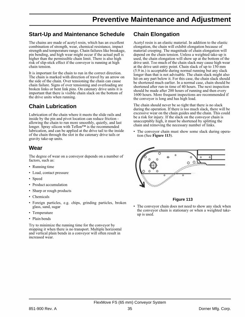
Chain ElongationAcetyl resin is an elastic material. In addition to the elastic elongation, the chain will exhibit elongation because of material creeping. The magnitude of chain elongation will depend on the chain tension. Unless a weighted take-up is used, the chain elongation will show up at the bottom of the drive unit. Too much of the chain slack may cause high wear at the drive unit entry point. Chain slack of up to 150 mm (5.9 in.) is acceptable during normal running but any slack longer than that is not advisable. The chain slack might also hit on any part below it. For this case, the chain slack should be shortened much earlier. In a normal case, chain should be shortened after run-in time of 40 hours. The next inspection should be made after 200 hours of running and then every 1600 hours. More frequent inspections are recommended if the conveyor is long and has high load.The chain should never be so tight that there is no slack during the operation. If there is too much slack, there will be excessive wear on the chain guides and the chain. This could be a risk for injury. If the slack on the conveyor chain is unacceptably high, it must be shortened by splitting the chain and removing the necessary number of links.� The conveyor chain must show some slack during opera-
tion (See Figure 113). Figure 113
Figure 113
� The conveyor chain does not need to show any slack whenthe conveyor chain is stationary or when a weighted take-up is used.
851-900 Rev. A 35 Dorner Mfg. Corp.
FlexMove FS (65 mm) Conveyor System
Preventive Maintenance and Adjustment
InspectionVisually check the slide rail in horizontal and vertical bends after every 200 hours of operation. The chain can stay in place during the inspection. Replace any worn out slide rail. Remove the chain from the conveyor and inspect the slide rail carefully once every 1500 hours of operation. Check for any worn out slide rail and any other unusual conditions and make necessary replacement. Clean up any dirt accumulation in the conveyor beam, especially before any plain bends, wheel bends, drive unit, and idler end.Drive UnitThe drive unit can be equipped with different gear motor brands. Please follow the maintenance recommendations from the manufacturer.
Maintenance ScheduleMaintenance is recommended to be carried out every 3rd, 6th and 12th month, and subsequently every 6th month, considering the running condition. Following are the recommended actions to be carried out:
First 3rd Month, 6th Month, and Every 6th Month Following� Shorten the chain, if required.� Visually inspect the condition of the slide rail, sprocket,
wheel, and chain guides.� Check any high wear part on the conveyor, and replace
when necessary.� Clean up any foreign accumulation that might block the
smooth flow of the conveyor.� Check the gearbox oil level and top off when necessary.� Check all support structures, slide guides, and conveyor
joints for looseness. Replace when necessary.
Checking Slide Rail with the Conveyor Chain in Place
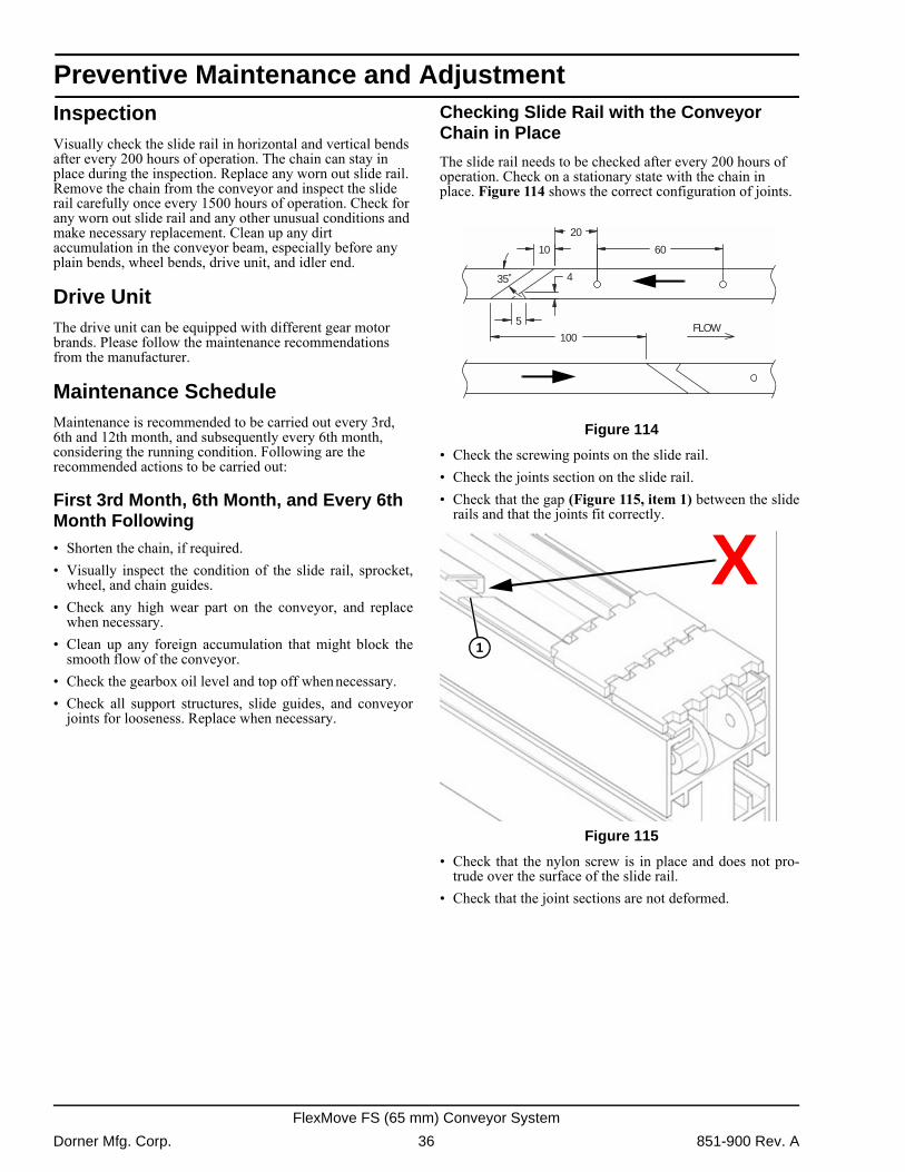
The slide rail needs to be checked after every 200 hours of operation. Check on a stationary state with the chain in place. Figure 114 shows the correct configuration of joints.
Figure 114
Figure 114
� Check the screwing points on the slide rail.� Check the joints section on the slide rail.� Check that the gap (Figure 115, item 1) between the slide
rails and that the joints fit correctly. Figure 115
Figure 115
� Check that the nylon screw is in place and does not pro-trude over the surface of the slide rail.
� Check that the joint sections are not deformed.
FLOW
10
20
60
35˚
5
4
100
1
X
Dorner Mfg. Corp. 36 851-900 Rev. A
FlexMove FS (65 mm) Conveyor System
Preventive Maintenance and Adjustment
Checks When the Chain is RemovedThe slide rail needs to be checked once a year or after 1500 hours of operation. The chain should be removed from the conveyor beam for checking the slide rail. Check carefully on the condition of wear and the screws.
Horizontal Bends
Horizontal bends need to be checked carefully after every 200 hours of operation.Check the inner slide rail in horizontal bends carefully, since the friction here is particularly high. The conveyor chain develops more pressure on the inner slide rail compared to the outer slide rail.� Check the slide rail for scratches and notches.� Replace the slide rail and the screws, if necessary.� Clean the conveyor chain and check the condition of the
chains.� Clean the conveyor beam.
Safety Devices
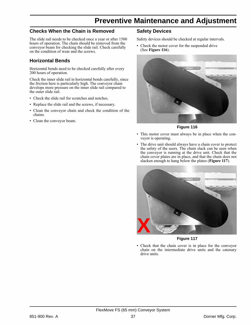
Safety devices should be checked at regular intervals.� Check the motor cover for the suspended drive
(See Figure 116). Figure 116
Figure 116
� This motor cover must always be in place when the con-veyor is operating.
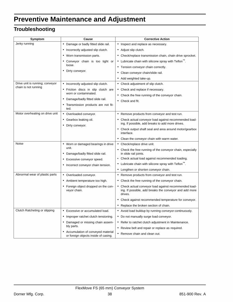
� The drive unit should always have a chain cover to protectthe safety of the users. The chain slack can be seen whenthe conveyor is running at the drive unit. Check that thechain cover plates are in place, and that the chain does notslacken enough to hang below the plates (Figure 117).
Figure 117
Figure 117
� Check that the chain cover is in place for the conveyorchain on the intermediate drive units and the catenarydrive units.
X
851-900 Rev. A 37 Dorner Mfg. Corp.
FlexMove FS (65 mm) Conveyor System
Preventive Maintenance and Adjustment
TroubleshootingSymptom Cause Corrective Action
Jerky running � Damage or badly fitted slide rail.
� Incorrectly adjusted slip clutch.
� Worn transmission parts.
� Conveyor chain is too tight orloose.
� Dirty conveyor.
� Inspect and replace as necessary.
� Adjust slip clutch.
� Check/replace transmission chain, chain drive sprocket.
� Lubricate chain with silicone spray with Teflon™.
� Tension conveyor chain correctly.
� Clean conveyor chain/slide rail.
� Add weighted take-up.
Drive unit is running; conveyor chain is not running
� Incorrectly adjusted slip clutch.
� Friction discs in slip clutch areworn or contaminated.
� Damage/badly fitted slide rail.
� Transmission products are not fit-ted.
� Check adjustment of slip clutch.
� Check and replace if necessary.
� Check the free running of the conveyor chain.
� Check and fit.
Motor overheating on drive unit � Overloaded conveyor.
� Gearbox leaking oil.
� Dirty conveyor.
� Remove products from conveyor and test run.
� Check actual conveyor load against recommended load-ing. If possible, add breaks to add more drives.
� Check output shaft seal and area around motor/gearboxinterface.
� Clean the conveyor chain with warm water.
Noise � Worn or damaged bearings in driveunit.
� Damage/badly fitted slide rail.
� Excessive conveyor speed.
� Incorrect conveyor chain tension.
� Check/replace drive unit.
� Check the free running of the conveyor chain, especiallyin slide rail joints.
• Check actual load against recommended loading.
� Lubricate chain with silicone spray with Teflon™.
� Lengthen or shorten conveyor chain.
Abnormal wear of plastic parts � Overloaded conveyor.
� Ambient temperature too high.
� Foreign object dropped on the con-veyor chain.
� Remove products from conveyor and test run.
� Check the free running of the conveyor chain.
� Check actual conveyor load against recommended load-ing. If possible, add breaks the conveyor and add moredrives.
� Check against recommended temperature for conveyor.
� Replace the broken section of chain.
Clutch Ratcheting or slipping � Excessive or accumulated load.
� Improper ratchet clutch tensioning.
� Damaged or missing chain assem-bly parts.
� Accumulation of conveyed materialor foreign objects inside of casing.
� Avoid load buildup by running conveyor continuously.
� Do not manually surge load conveyor.
� Refer to ratchet clutch adjustment in Maintenance.
� Review belt and repair or replace as required.
� Remove chain and clean out.
Dorner Mfg. Corp. 38 851-900 Rev. A
FlexMove FS (65 mm) Conveyor System
Preventive Maintenance and Adjustment
Required Tools� 3/32" hex wrench� 3 mm hex wrench� 4 mm hex wrench� 5 mm hex wrench� 6 mm hex wrench� 8 mm hex wrench� 10 mm wrench� 13 mm wrench� 16 mm wrench� Chain Removal Tool� Slide Rail Cutter� Drill Fixtures for Slide Rails� Riveting ToolConveyor Chain Replacement
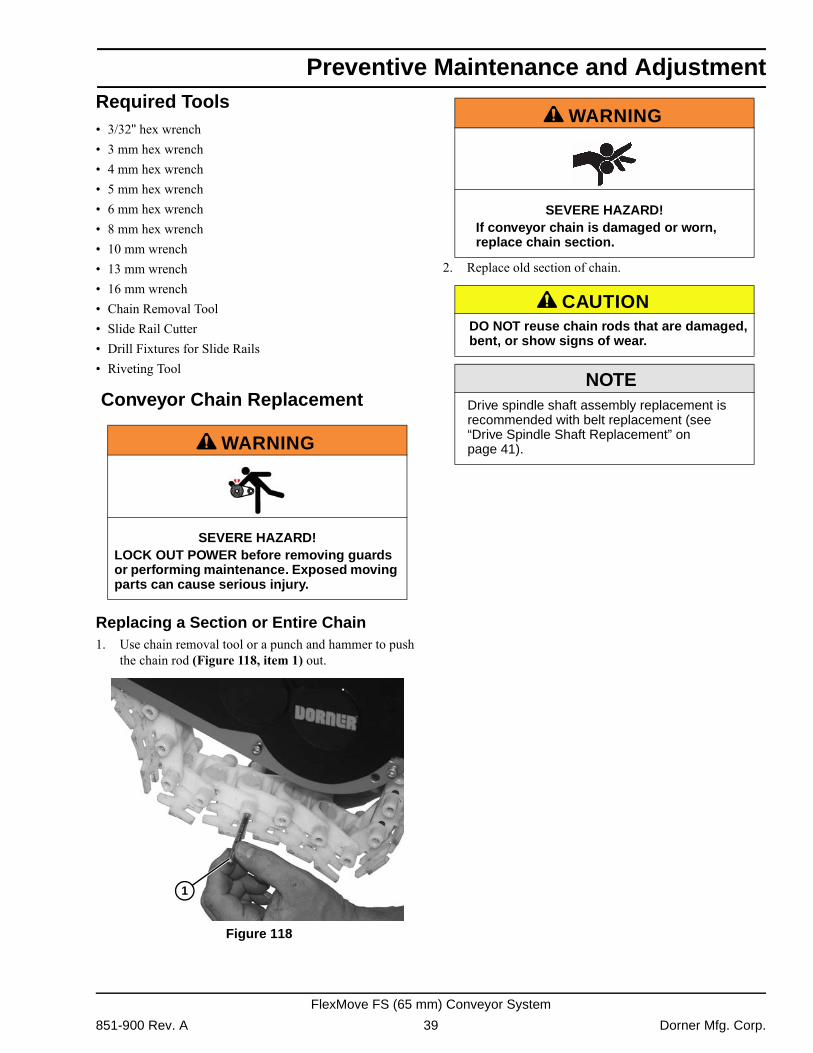
Replacing a Section or Entire Chain1. Use chain removal tool or a punch and hammer to push
the chain rod (Figure 118, item 1) out. Figure 118
Figure 118
2. Replace old section of chain.
A WARNING
SEVERE HAZARD!LOCK OUT POWER before removing guards or performing maintenance. Exposed moving parts can cause serious injury.
1
A WARNING
SEVERE HAZARD!If conveyor chain is damaged or worn, replace chain section.
A CAUTIONDO NOT reuse chain rods that are damaged, bent, or show signs of wear.
NOTEDrive spindle shaft assembly replacement is recommended with belt replacement (see “Drive Spindle Shaft Replacement” on page 41).
851-900 Rev. A 39 Dorner Mfg. Corp.
FlexMove FS (65 mm) Conveyor System
Preventive Maintenance and Adjustment
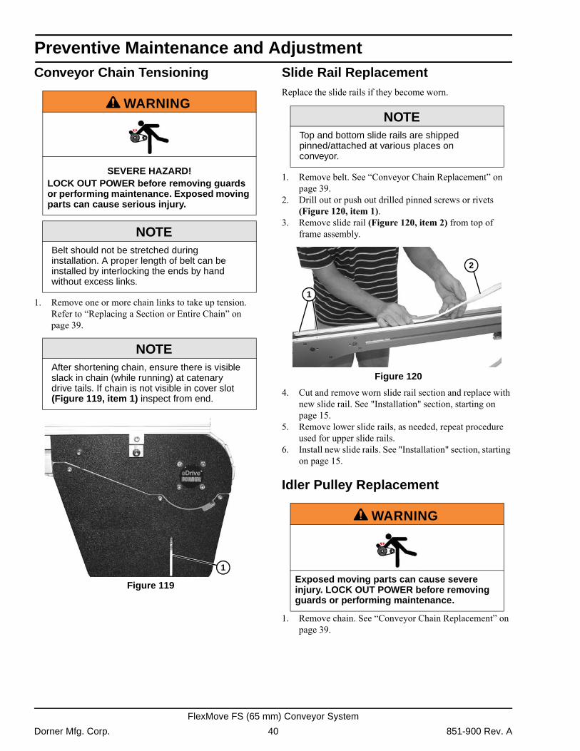
Conveyor Chain Tensioning1. Remove one or more chain links to take up tension. Refer to �Replacing a Section or Entire Chain� on page 39.
Figure 119
Figure 119
Slide Rail ReplacementReplace the slide rails if they become worn.
1. Remove belt. See �Conveyor Chain Replacement� on page 39.
2. Drill out or push out drilled pinned screws or rivets (Figure 120, item 1).
3. Remove slide rail (Figure 120, item 2) from top of frame assembly.
Figure 120
Figure 120
4. Cut and remove worn slide rail section and replace with new slide rail. See "Installation" section, starting on page 15.
5. Remove lower slide rails, as needed, repeat procedure used for upper slide rails.
6. Install new slide rails. See "Installation" section, starting on page 15.
Idler Pulley Replacement
1. Remove chain. See �Conveyor Chain Replacement� on page 39.
A WARNING
SEVERE HAZARD!LOCK OUT POWER before removing guards or performing maintenance. Exposed moving parts can cause serious injury.
NOTEBelt should not be stretched during installation. A proper length of belt can be installed by interlocking the ends by hand without excess links.
NOTEAfter shortening chain, ensure there is visible slack in chain (while running) at catenary drive tails. If chain is not visible in cover slot (Figure 119, item 1) inspect from end.
1
NOTETop and bottom slide rails are shipped pinned/attached at various places on conveyor.
A WARNING
Exposed moving parts can cause severe injury. LOCK OUT POWER before removing guards or performing maintenance.
2
1
Dorner Mfg. Corp. 40 851-900 Rev. A
FlexMove FS (65 mm) Conveyor System
Preventive Maintenance and Adjustment
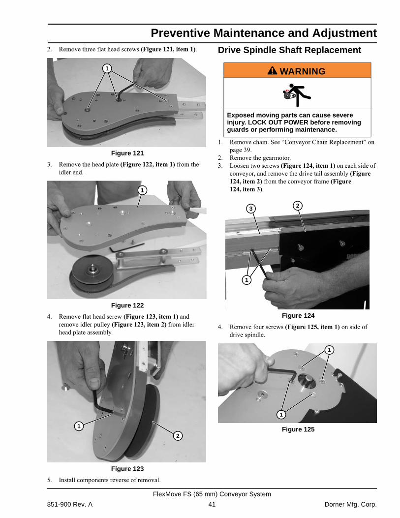
2. Remove three flat head screws (Figure 121, item 1).Figure 121
Figure 121
3. Remove the head plate (Figure 122, item 1) from the idler end.
Figure 122
Figure 122
4. Remove flat head screw (Figure 123, item 1) and remove idler pulley (Figure 123, item 2) from idler head plate assembly.
Figure 123
Figure 123
5. Install components reverse of removal.
Drive Spindle Shaft Replacement
1. Remove chain. See �Conveyor Chain Replacement� on page 39.
2. Remove the gearmotor.3. Loosen two screws (Figure 124, item 1) on each side of
conveyor, and remove the drive tail assembly (Figure 124, item 2) from the conveyor frame (Figure 124, item 3).
Figure 124
Figure 124
4. Remove four screws (Figure 125, item 1) on side of drive spindle.
Figure 125
Figure 125
1
1
2
1
A WARNING
Exposed moving parts can cause severe injury. LOCK OUT POWER before removing guards or performing maintenance.
2
1
3
1
1
851-900 Rev. A 41 Dorner Mfg. Corp.
FlexMove FS (65 mm) Conveyor System
Preventive Maintenance and Adjustment
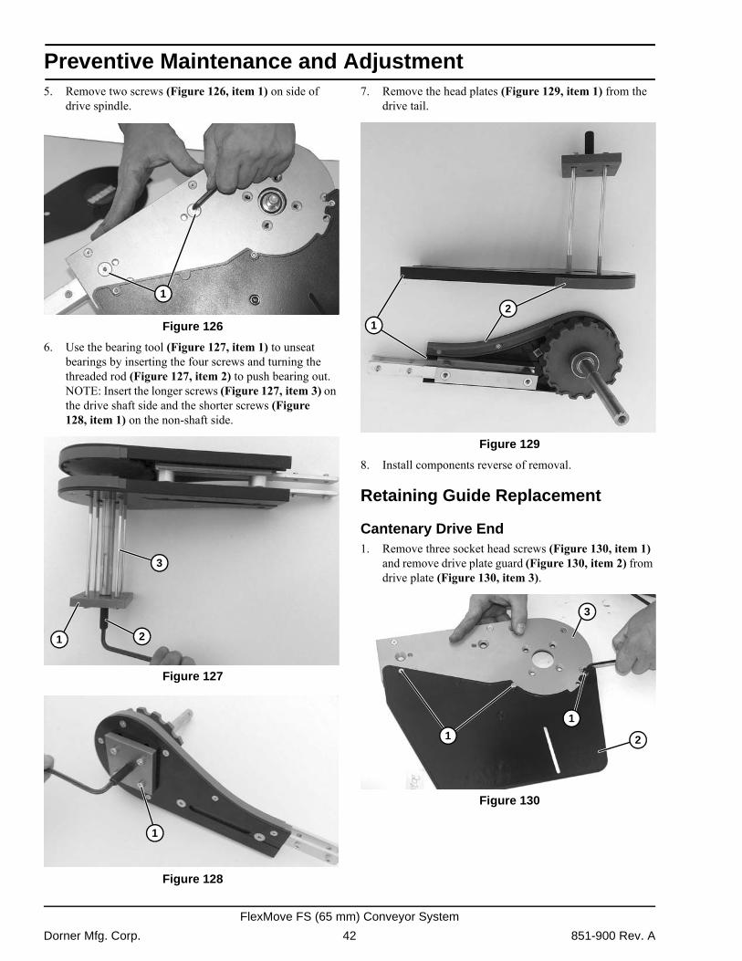
5. Remove two screws (Figure 126, item 1) on side ofdrive spindle. Figure 126
Figure 126
6. Use the bearing tool (Figure 127, item 1) to unseat bearings by inserting the four screws and turning the threaded rod (Figure 127, item 2) to push bearing out. NOTE: Insert the longer screws (Figure 127, item 3) on the drive shaft side and the shorter screws (Figure 128, item 1) on the non-shaft side.
Figure 127
Figure 127 Figure 128
Figure 128
7. Remove the head plates (Figure 129, item 1) from the drive tail.
Figure 129
Figure 129
8. Install components reverse of removal.
Retaining Guide Replacement
Cantenary Drive End1. Remove three socket head screws (Figure 130, item 1)
and remove drive plate guard (Figure 130, item 2) from drive plate (Figure 130, item 3).
Figure 130
Figure 130
1
21
3
1
1
2
1
1
2
3
Dorner Mfg. Corp. 42 851-900 Rev. A
FlexMove FS (65 mm) Conveyor System
Preventive Maintenance and Adjustment
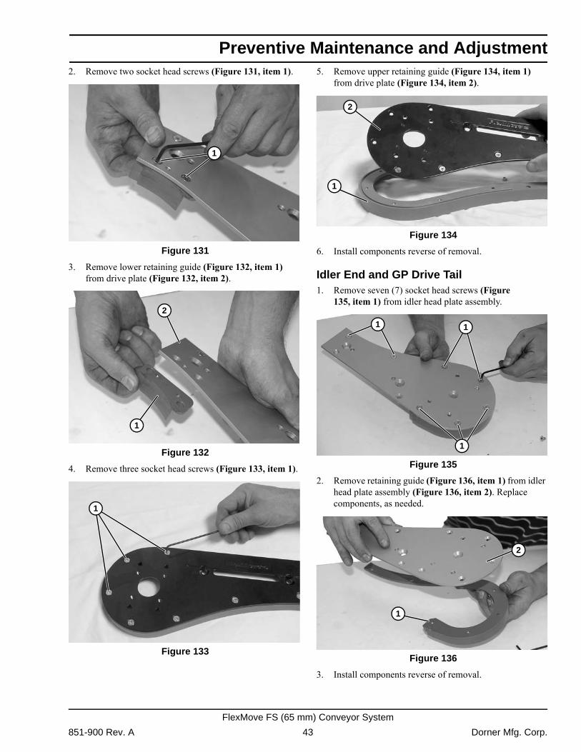
2. Remove two socket head screws (Figure 131, item 1).Figure 131
Figure 131
3. Remove lower retaining guide (Figure 132, item 1) from drive plate (Figure 132, item 2).
Figure 132
Figure 132
4. Remove three socket head screws (Figure 133, item 1). Figure 133
Figure 133
5. Remove upper retaining guide (Figure 134, item 1) from drive plate (Figure 134, item 2).
Figure 134
Figure 134
6. Install components reverse of removal.
Idler End and GP Drive Tail1. Remove seven (7) socket head screws (Figure
135, item 1) from idler head plate assembly. Figure 135
Figure 135
2. Remove retaining guide (Figure 136, item 1) from idler head plate assembly (Figure 136, item 2). Replace components, as needed.
Figure 136
Figure 136
3. Install components reverse of removal.
1
1
2
1
1
2
1
1 1
1
2
851-900 Rev. A 43 Dorner Mfg. Corp.
FlexMove FS (65 mm) Conveyor System

Preventive Maintenance and Adjustment
Top Running Drive1. Remove four socket head screws (Figure 137, item 1).Remove drive package (Figure 137, item 2) from drive motor mounting bracket (Figure 137, item 3).
Figure 137
Figure 137
2. Loosen set screw (Figure 138, item 1) and remove belt hold down wheel (Figure 138, item 2).
Figure 138
Figure 138
3. Repeat on opposite side.4. Remove four socket head screws (Figure 139, item 1)
securing belt hold down tabs (Figure 139, item 2) to drive assembly (Figure 139, item 3).
Figure 139
Figure 139
5. Repeat on opposite side.
6. Use belt removal tool #203480 (Figure 140, item 1) or a punch and hammer to push the belt rod out by striking the rod end.
Figure 140
Figure 140
7. Remove four hex head cap screws (Figure 141, item 1) and remove drive motor mounting plate (Figure 141, item 2).
Figure 141
Figure 141
2
1
3
2
1
1
1
3
2
A WARNING
SEVERE HAZARD!If conveyor belt is damaged or worn, replace belt section.
1
2
1
Dorner Mfg. Corp. 44 851-900 Rev. A
FlexMove FS (65 mm) Conveyor System
Preventive Maintenance and Adjustment
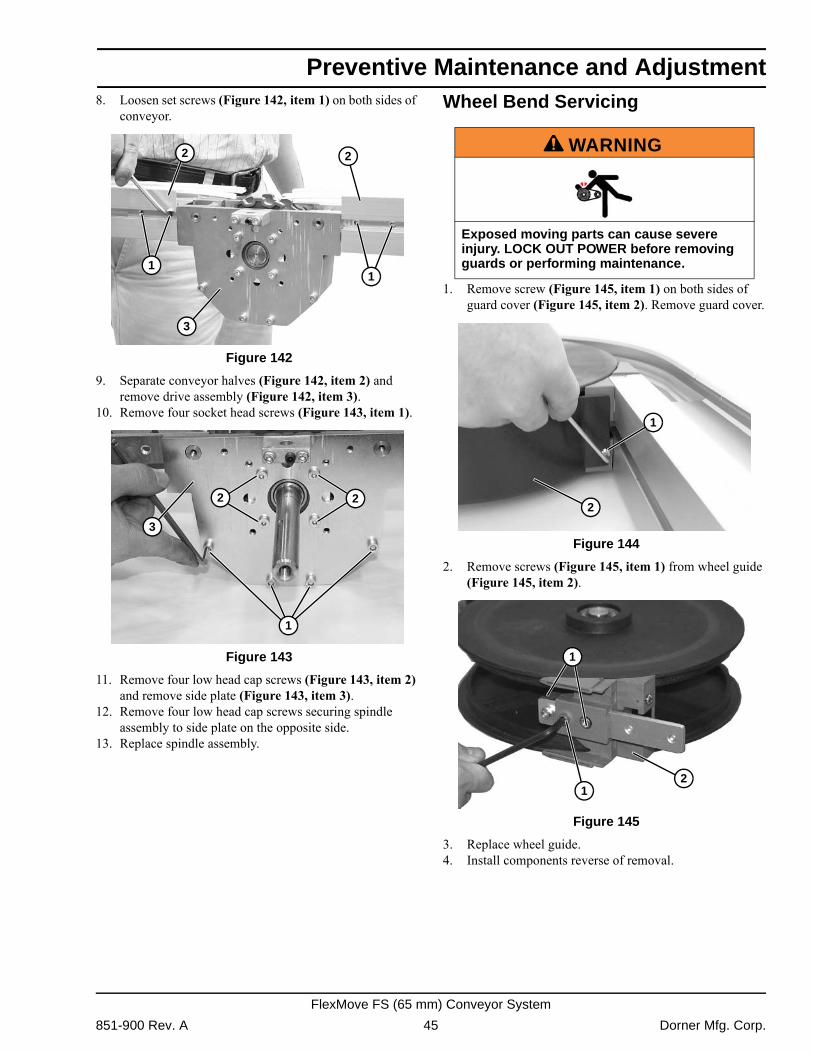
8. Loosen set screws (Figure 142, item 1) on both sides ofconveyor. Figure 142
Figure 142
9. Separate conveyor halves (Figure 142, item 2) and remove drive assembly (Figure 142, item 3).
10. Remove four socket head screws (Figure 143, item 1). Figure 143
Figure 143
11. Remove four low head cap screws (Figure 143, item 2) and remove side plate (Figure 143, item 3).
12. Remove four low head cap screws securing spindle assembly to side plate on the opposite side.
13. Replace spindle assembly.
Wheel Bend Servicing
1. Remove screw (Figure 145, item 1) on both sides of guard cover (Figure 145, item 2). Remove guard cover.
Figure 144
Figure 144
2. Remove screws (Figure 145, item 1) from wheel guide (Figure 145, item 2).
Figure 145
Figure 145
3. Replace wheel guide.4. Install components reverse of removal.
3
11
22
1
22
3
A WARNING
Exposed moving parts can cause severe injury. LOCK OUT POWER before removing guards or performing maintenance.
1
2
1
1
2
851-900 Rev. A 45 Dorner Mfg. Corp.
FlexMove FS (65 mm) Conveyor System
Preventive Maintenance and Adjustment
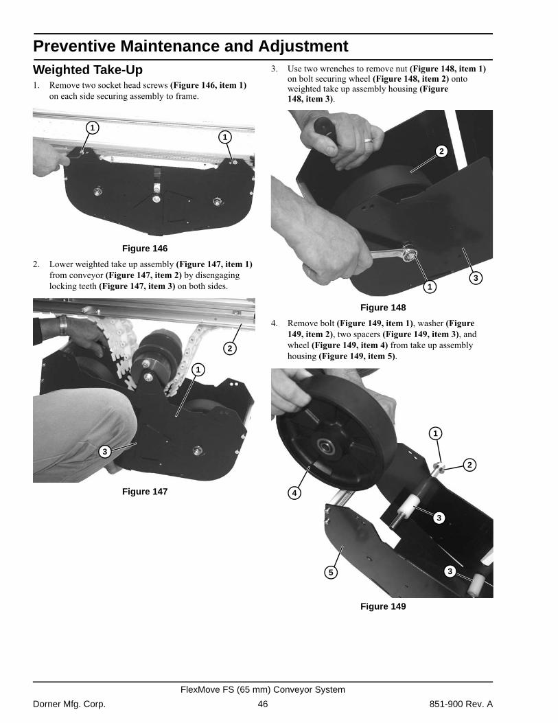
Weighted Take-Up1. Remove two socket head screws (Figure 146, item 1)on each side securing assembly to frame. Figure 146
Figure 146
2. Lower weighted take up assembly (Figure 147, item 1) from conveyor (Figure 147, item 2) by disengaging locking teeth (Figure 147, item 3) on both sides.
Figure 147
Figure 147
3. Use two wrenches to remove nut (Figure 148, item 1) on bolt securing wheel (Figure 148, item 2) onto weighted take up assembly housing (Figure 148, item 3).
Figure 148
Figure 148
4. Remove bolt (Figure 149, item 1), washer (Figure 149, item 2), two spacers (Figure 149, item 3), and wheel (Figure 149, item 4) from take up assembly housing (Figure 149, item 5).
Figure 149
Figure 149
11
2
1
3
2
13
4
1
2
3
35
Dorner Mfg. Corp. 46 851-900 Rev. A
FlexMove FS (65 mm) Conveyor System
Preventive Maintenance and Adjustment
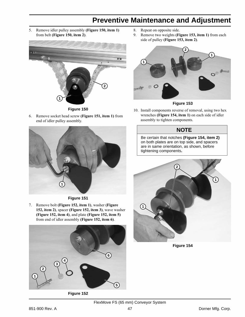
5. Remove idler pulley assembly (Figure 150, item 1)from belt (Figure 150, item 2). Figure 150
Figure 150
6. Remove socket head screw (Figure 151, item 1) from end of idler pulley assembly.
Figure 151
Figure 151
7. Remove bolt (Figure 152, item 1), washer (Figure 152, item 2), spacer (Figure 152, item 3), wave washer (Figure 152, item 4), and plate (Figure 152, item 5) from end of idler assembly (Figure 152, item 6).
Figure 152
Figure 152
8. Repeat on opposite side.9. Remove two weights (Figure 153, item 1) from each
side of pulley (Figure 153, item 2). Figure 153
Figure 153
10. Install components reverse of removal, using two hex wrenches (Figure 154, item 1) on each side of idler assembly to tighten components.
Figure 154
Figure 154
2
1
1
5
1
23
46
NOTEBe certain that notches (Figure 154, item 2) on both plates are on top side, and spacers are in same orientation, as shown, before tightening components.
1
21
1
1
2
851-900 Rev. A 47 Dorner Mfg. Corp.
FlexMove FS (65 mm) Conveyor System
Preventive Maintenance and Adjustment
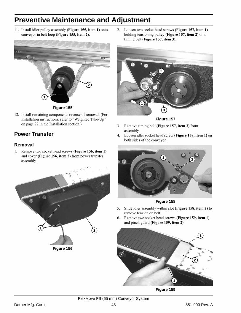
11. Install idler pulley assembly (Figure 155, item 1) ontoconveyor in belt loop (Figure 155, item 2). Figure 155
Figure 155
12. Install remaining components reverse of removal. (For installation instructions, refer to �Weighted Take-Up� on page 22 in the Installation section.)
Power Transfer
Removal1. Remove two socket head screws (Figure 156, item 1)
and cover (Figure 156, item 2) from power transfer assembly.
Figure 156
Figure 156
2. Loosen two socket head screws (Figure 157, item 1) holding tensioning pulley (Figure 157, item 2) onto timing belt (Figure 157, item 3).
Figure 157
Figure 157
3. Remove timing belt (Figure 157, item 3) from assembly.
4. Loosen idler socket head screw (Figure 158, item 1) on both sides of the conveyor.
Figure 158
Figure 158
5. Slide idler assembly within slot (Figure 158, item 2) to remove tension on belt.
6. Remove two socket head screws (Figure 159, item 1) and pinch guard (Figure 159, item 2).
Figure 159
Figure 159
2
1
21
2
1
3
1 2
2
1
1
Dorner Mfg. Corp. 48 851-900 Rev. A
FlexMove FS (65 mm) Conveyor System
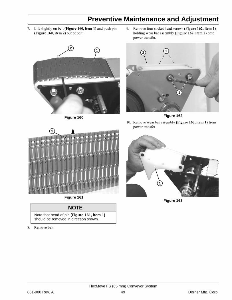
Preventive Maintenance and Adjustment
7. Lift slightly on belt (Figure 160, item 1) and push pin(Figure 160, item 2) out of belt. Figure 160
Figure 160 Figure 161
Figure 161
8. Remove belt.
9. Remove four socket head screws (Figure 162, item 1) holding wear bar assembly (Figure 162, item 2) onto power transfer.
Figure 162
Figure 162
10. Remove wear bar assembly (Figure 163, item 1) from power transfer.
Figure 163
Figure 163
NOTENote that head of pin (Figure 161, item 1) should be removed in direction shown.
21
1
1
2 1
1
851-900 Rev. A 49 Dorner Mfg. Corp.
FlexMove FS (65 mm) Conveyor System
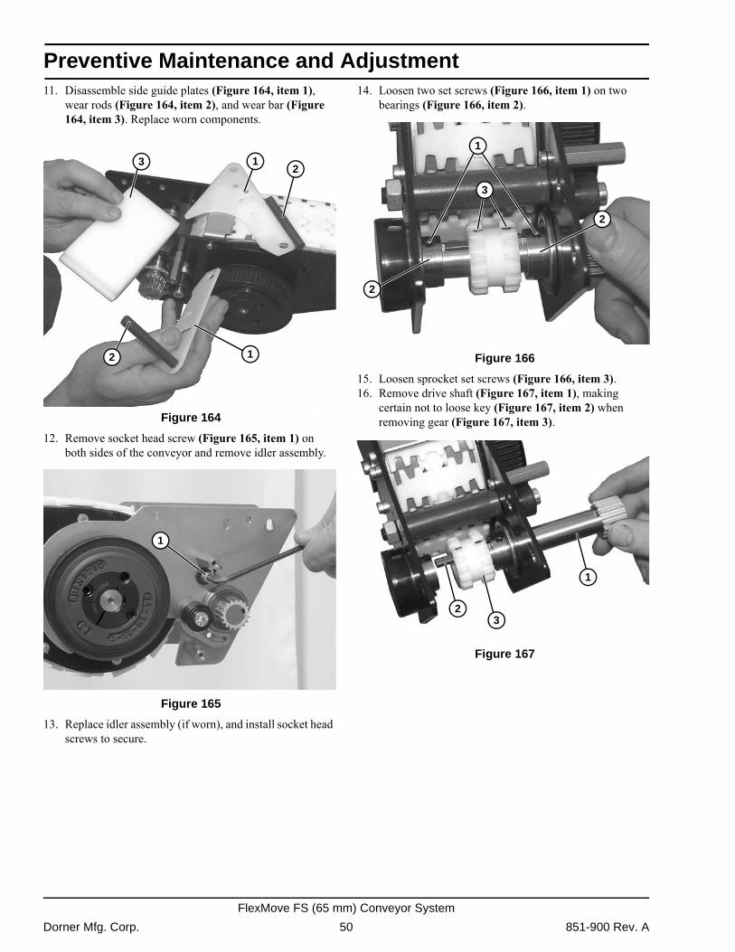
Preventive Maintenance and Adjustment
11. Disassemble side guide plates (Figure 164, item 1),wear rods (Figure 164, item 2), and wear bar (Figure 164, item 3). Replace worn components.
Figure 164
Figure 164
12. Remove socket head screw (Figure 165, item 1) on both sides of the conveyor and remove idler assembly.
Figure 165
Figure 165
13. Replace idler assembly (if worn), and install socket head screws to secure.
14. Loosen two set screws (Figure 166, item 1) on two bearings (Figure 166, item 2).
Figure 166
Figure 166
15. Loosen sprocket set screws (Figure 166, item 3).16. Remove drive shaft (Figure 167, item 1), making
certain not to loose key (Figure 167, item 2) when removing gear (Figure 167, item 3).
Figure 167
Figure 167
1
32
1
2
1
1
2
2
3
1
32
Dorner Mfg. Corp. 50 851-900 Rev. A
FlexMove FS (65 mm) Conveyor System
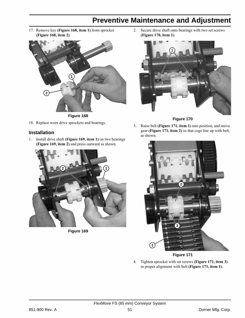
Preventive Maintenance and Adjustment
17. Remove key (Figure 168, item 1) from sprocket(Figure 168, item 2). Figure 168
Figure 168
18. Replace worn drive sprockets and bearings.
Installation1. Install drive shaft (Figure 169, item 1) on two bearings
(Figure 169, item 2) and press outward as shown. Figure 169
Figure 169
2. Secure drive shaft onto bearings with two set screws (Figure 170, item 1).
Figure 170
Figure 170
3. Raise belt (Figure 171, item 1) into position, and move gear (Figure 171, item 2) so that cogs line up with belt, as shown.
Figure 171
Figure 171
4. Tighten sprocket with set screws (Figure 171, item 3) in proper alignment with belt (Figure 171, item 1).
2
1
12
1
2
1
3
851-900 Rev. A 51 Dorner Mfg. Corp.
FlexMove FS (65 mm) Conveyor System
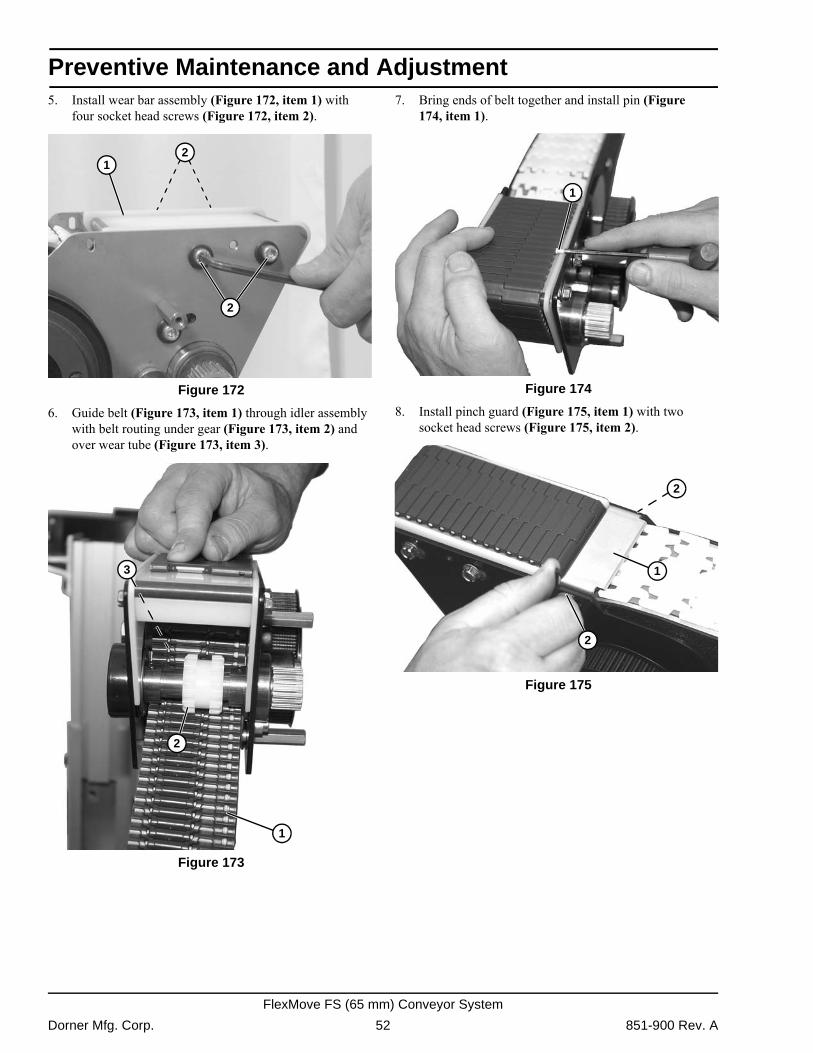
Preventive Maintenance and Adjustment
5. Install wear bar assembly (Figure 172, item 1) withfour socket head screws (Figure 172, item 2). Figure 172
Figure 172
6. Guide belt (Figure 173, item 1) through idler assembly with belt routing under gear (Figure 173, item 2) and over wear tube (Figure 173, item 3).
Figure 173
Figure 173
7. Bring ends of belt together and install pin (Figure 174, item 1).
Figure 174
Figure 174
8. Install pinch guard (Figure 175, item 1) with two socket head screws (Figure 175, item 2).
Figure 175
Figure 175
2
12
1
2
3
1
1
2
2
Dorner Mfg. Corp. 52 851-900 Rev. A
FlexMove FS (65 mm) Conveyor System
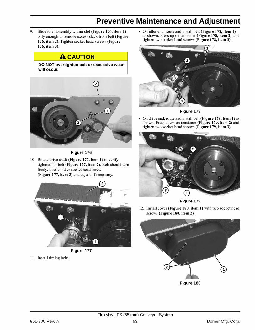
Preventive Maintenance and Adjustment
9. Slide idler assembly within slot (Figure 176, item 1)only enough to remove excess slack from belt (Figure 176, item 2). Tighten socket head screws (Figure 176, item 3).
Figure 176
Figure 176
10. Rotate drive shaft (Figure 177, item 1) to verify tightness of belt (Figure 177, item 2). Belt should turn freely. Loosen idler socket head screw (Figure 177, item 3) and adjust, if necessary.
Figure 177
Figure 177
11. Install timing belt:
� On idler end, route and install belt (Figure 178, item 1) as shown. Press up on tensioner (Figure 178, item 2) and tighten two socket head screws (Figure 178, item 3).
Figure 178
Figure 178
� On drive end, route and install belt (Figure 179, item 1) as shown. Press down on tensioner (Figure 179, item 2) and tighten two socket head screws (Figure 179, item 3)
Figure 179
Figure 179
12. Install cover (Figure 180, item 1) with two socket head screws (Figure 180, item 2).
Figure 180
Figure 180
A CAUTIONDO NOT overtighten belt or excessive wear will occur.
3
2
1
3
2
1
2
1
3
31
2
12
851-900 Rev. A 53 Dorner Mfg. Corp.
FlexMove FS (65 mm) Conveyor System
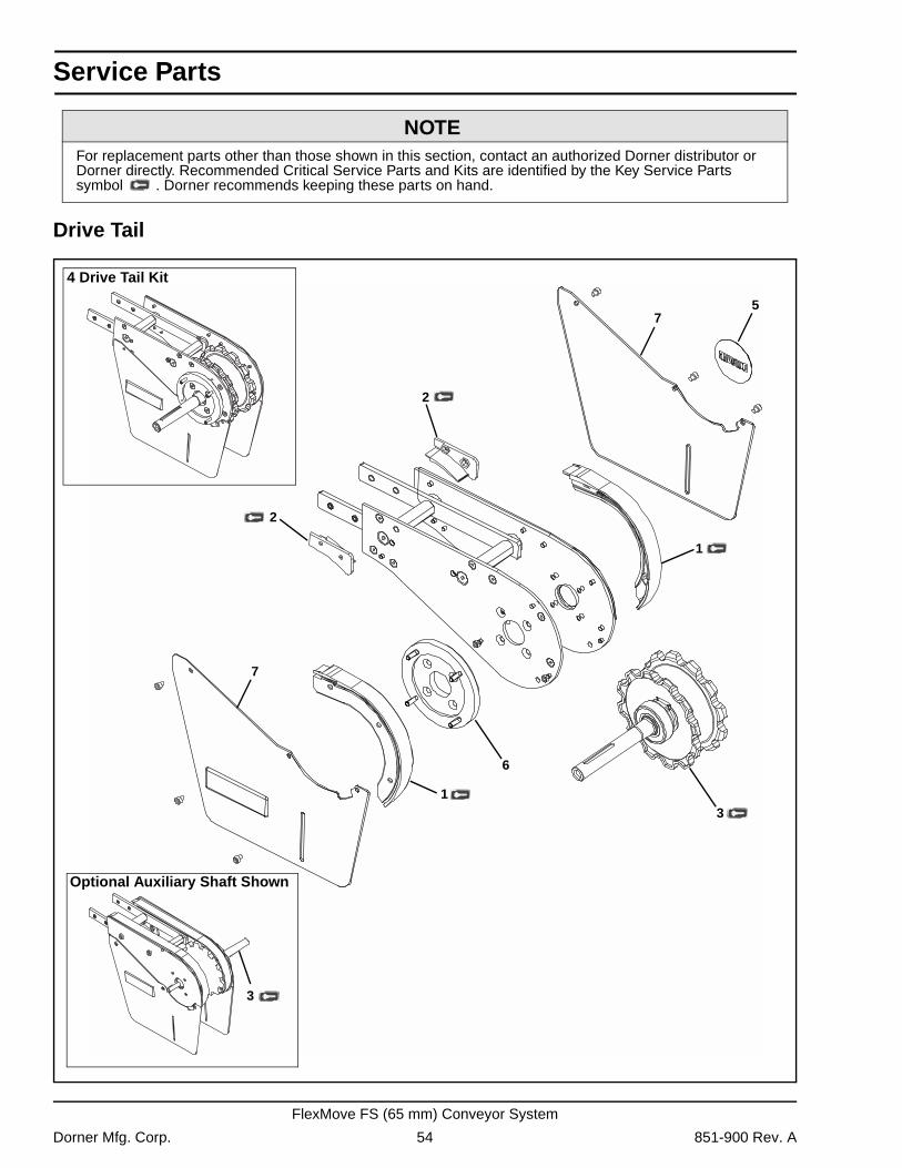
Service Parts
Drive Tail
NOTEFor replacement parts other than those shown in this section, contact an authorized Dorner distributor or Dorner directly. Recommended Critical Service Parts and Kits are identified by the Key Service Parts symbol . Dorner recommends keeping these parts on hand.
1
1
Optional Auxiliary Shaft Shown
4 Drive Tail Kit
3
3
2
2
6
7
7
5
Dorner Mfg. Corp. 54 851-900 Rev. A
FlexMove FS (65 mm) Conveyor System
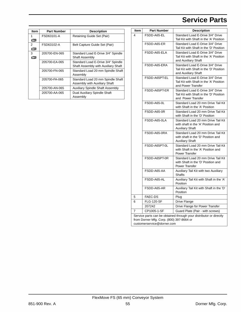
Service Parts
Item Part Number Description1 FSD63101-A Retaining Guide Set (Pair)
2 FSD63102-A Belt Capture Guide Set (Pair)
3 205700-EN-065 Standard Load E-Drive 3/4” Spindle Shaft Assembly
205700-EA-065 Standard Load E-Drive 3/4” Spindle Shaft Assembly with Auxiliary Shaft
205700-FN-065 Standard Load 20 mm Spindle Shaft Assembly
205700-FA-065 Standard Load 20 mm Spindle Shaft Assembly with Auxiliary Shaft
205700-AN-065 Auxiliary Spindle Shaft Assembly
205700-AA-065 Dual Auxiliary Spindle Shaft Assembly
4 FSDD-A65-EL Standard Load E-Drive 3/4” Drive Tail Kit with Shaft in the 'A' Position
FSDD-A65-ER Standard Load E-Drive 3/4” Drive Tail Kit with Shaft in the 'D' Position
FSDD-A65-ELA Standard Load E-Drive 3/4” Drive Tail Kit with Shaft in the 'A' Position and Auxiliary Shaft
FSDD-A65-ERA Standard Load E-Drive 3/4” Drive Tail Kit with Shaft in the 'D' Position and Auxiliary Shaft
FSDD-A65PT-EL Standard Load E-Drive 3/4” Drive Tail Kit with Shaft in the 'A' Position and Power Transfer
FSDD-A65PT-ER Standard Load E-Drive 3/4” Drive Tail Kit with Shaft in the 'D' Position and Power Transfer
FSDD-A65-0L Standard Load 20 mm Drive Tail Kit with Shaft in the 'A' Position
FSDD-A65-0R Standard Load 20 mm Drive Tail Kit with Shaft in the 'D' Position
FSDD-A65-0LA Standard Load 20 mm Drive Tail Kit with shaft in the 'A' Position and Auxiliary Shaft
FSDD-A65-0RA Standard Load 20 mm Drive Tail Kit with shaft in the 'D' Position and Auxiliary Shaft
FSDD-A65PT-0L Standard Load 20 mm Drive Tail Kit with Shaft in the 'A' Position and Power Transfer
FSDD-A65PT-0R Standard Load 20 mm Drive Tail Kit with Shaft in the 'D' Position and Power Transfer
FSDD-A65-AA Auxiliary Tail Kit with two Auxiliary Shafts
FSDD-A65-AL Auxiliary Tail Kit with Shaft in the 'A' Position
FSDD-A65-AR Auxiliary Tail Kit with Shaft in the 'D' Position
5 FAEC-DS Plug
6 FLG-120-SF Drive Flange
207242 Drive Flange for Power Transfer
7 CP1005-1-SF Guard Plate (Pair - with screws)
Service parts can be obtained through your distributor or directly from Dorner Mfg. Corp. (800) 397-8664 or [email protected]
Item Part Number Description
851-900 Rev. A 55 Dorner Mfg. Corp.
FlexMove FS (65 mm) Conveyor System
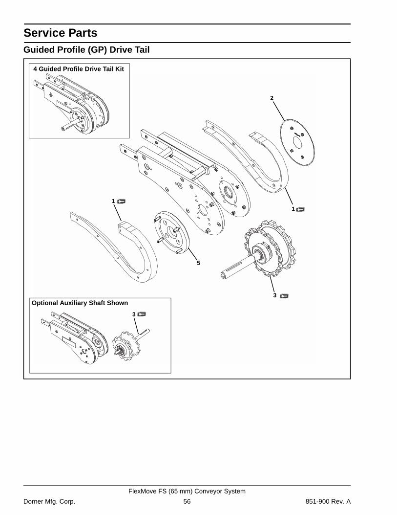
Service Parts
Guided Profile (GP) Drive Tail2
Optional Auxiliary Shaft Shown
4 Guided Profile Drive Tail Kit
3
11
3
5
Dorner Mfg. Corp. 56 851-900 Rev. A
FlexMove FS (65 mm) Conveyor System
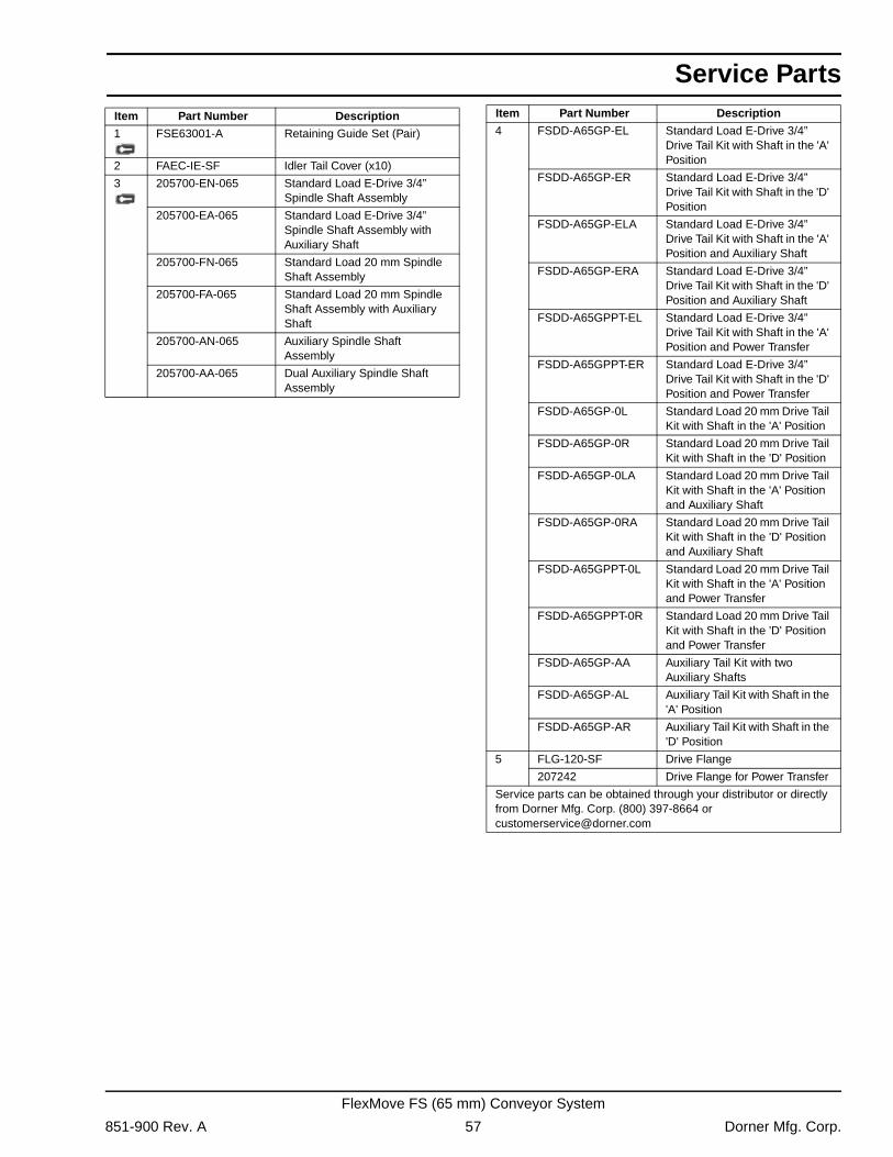
Service Parts
Item Part Number Description1 FSE63001-A Retaining Guide Set (Pair)
2 FAEC-IE-SF Idler Tail Cover (x10)
3 205700-EN-065 Standard Load E-Drive 3/4” Spindle Shaft Assembly
205700-EA-065 Standard Load E-Drive 3/4” Spindle Shaft Assembly with Auxiliary Shaft
205700-FN-065 Standard Load 20 mm Spindle Shaft Assembly
205700-FA-065 Standard Load 20 mm Spindle Shaft Assembly with Auxiliary Shaft
205700-AN-065 Auxiliary Spindle Shaft Assembly
205700-AA-065 Dual Auxiliary Spindle Shaft Assembly
4 FSDD-A65GP-EL Standard Load E-Drive 3/4” Drive Tail Kit with Shaft in the 'A' Position
FSDD-A65GP-ER Standard Load E-Drive 3/4” Drive Tail Kit with Shaft in the 'D' Position
FSDD-A65GP-ELA Standard Load E-Drive 3/4” Drive Tail Kit with Shaft in the 'A' Position and Auxiliary Shaft
FSDD-A65GP-ERA Standard Load E-Drive 3/4” Drive Tail Kit with Shaft in the 'D' Position and Auxiliary Shaft
FSDD-A65GPPT-EL Standard Load E-Drive 3/4” Drive Tail Kit with Shaft in the 'A' Position and Power Transfer
FSDD-A65GPPT-ER Standard Load E-Drive 3/4” Drive Tail Kit with Shaft in the 'D' Position and Power Transfer
FSDD-A65GP-0L Standard Load 20 mm Drive Tail Kit with Shaft in the 'A' Position
FSDD-A65GP-0R Standard Load 20 mm Drive Tail Kit with Shaft in the 'D' Position
FSDD-A65GP-0LA Standard Load 20 mm Drive Tail Kit with Shaft in the 'A' Position and Auxiliary Shaft
FSDD-A65GP-0RA Standard Load 20 mm Drive Tail Kit with Shaft in the 'D' Position and Auxiliary Shaft
FSDD-A65GPPT-0L Standard Load 20 mm Drive Tail Kit with Shaft in the 'A' Position and Power Transfer
FSDD-A65GPPT-0R Standard Load 20 mm Drive Tail Kit with Shaft in the 'D' Position and Power Transfer
FSDD-A65GP-AA Auxiliary Tail Kit with two Auxiliary Shafts
FSDD-A65GP-AL Auxiliary Tail Kit with Shaft in the 'A' Position
FSDD-A65GP-AR Auxiliary Tail Kit with Shaft in the 'D' Position
5 FLG-120-SF Drive Flange
207242 Drive Flange for Power Transfer
Service parts can be obtained through your distributor or directly from Dorner Mfg. Corp. (800) 397-8664 or [email protected]
Item Part Number Description
851-900 Rev. A 57 Dorner Mfg. Corp.
FlexMove FS (65 mm) Conveyor System
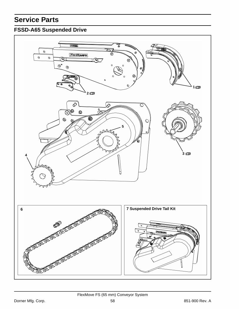
Service Parts
FSSD-A65 Suspended Drive5
1
2
34
6 7 Suspended Drive Tail Kit
Dorner Mfg. Corp. 58 851-900 Rev. A
FlexMove FS (65 mm) Conveyor System
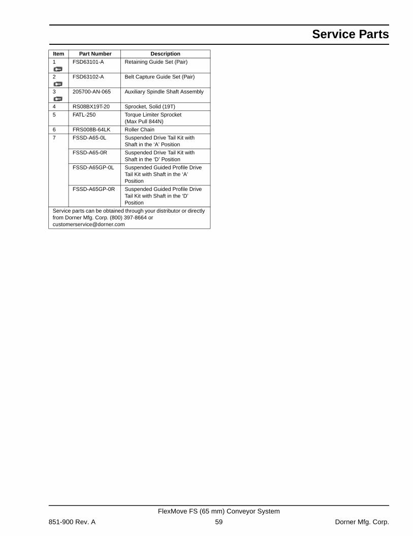
Service Parts
Item Part Number Description1 FSD63101-A Retaining Guide Set (Pair)
2 FSD63102-A Belt Capture Guide Set (Pair)
3 205700-AN-065 Auxiliary Spindle Shaft Assembly
4 RS08BX19T-20 Sprocket, Solid (19T)
5 FATL-250 Torque Limiter Sprocket (Max Pull 844N)
6 FRS008B-64LK Roller Chain
7 FSSD-A65-0L Suspended Drive Tail Kit with Shaft in the ‘A’ Position
FSSD-A65-0R Suspended Drive Tail Kit with Shaft in the ‘D’ Position
FSSD-A65GP-0L Suspended Guided Profile Drive Tail Kit with Shaft in the ‘A’ Position
FSSD-A65GP-0R Suspended Guided Profile Drive Tail Kit with Shaft in the ‘D’ Position
Service parts can be obtained through your distributor or directly from Dorner Mfg. Corp. (800) 397-8664 or [email protected]
851-900 Rev. A 59 Dorner Mfg. Corp.
FlexMove FS (65 mm) Conveyor System
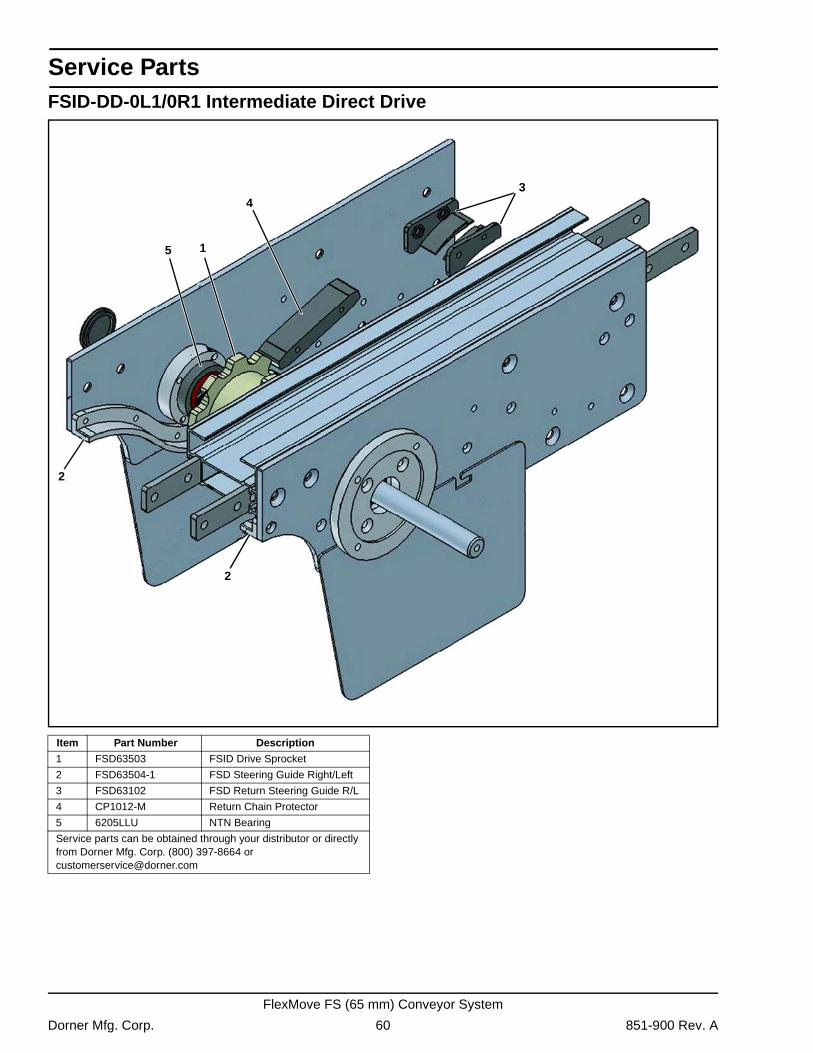
Service Parts
FSID-DD-0L1/0R1 Intermediate Direct Drive1
2
34
5
2
Item Part Number Description
1 FSD63503 FSID Drive Sprocket
2 FSD63504-1 FSD Steering Guide Right/Left
3 FSD63102 FSD Return Steering Guide R/L
4 CP1012-M Return Chain Protector
5 6205LLU NTN Bearing
Service parts can be obtained through your distributor or directly from Dorner Mfg. Corp. (800) 397-8664 or [email protected]
Dorner Mfg. Corp. 60 851-900 Rev. A
FlexMove FS (65 mm) Conveyor System
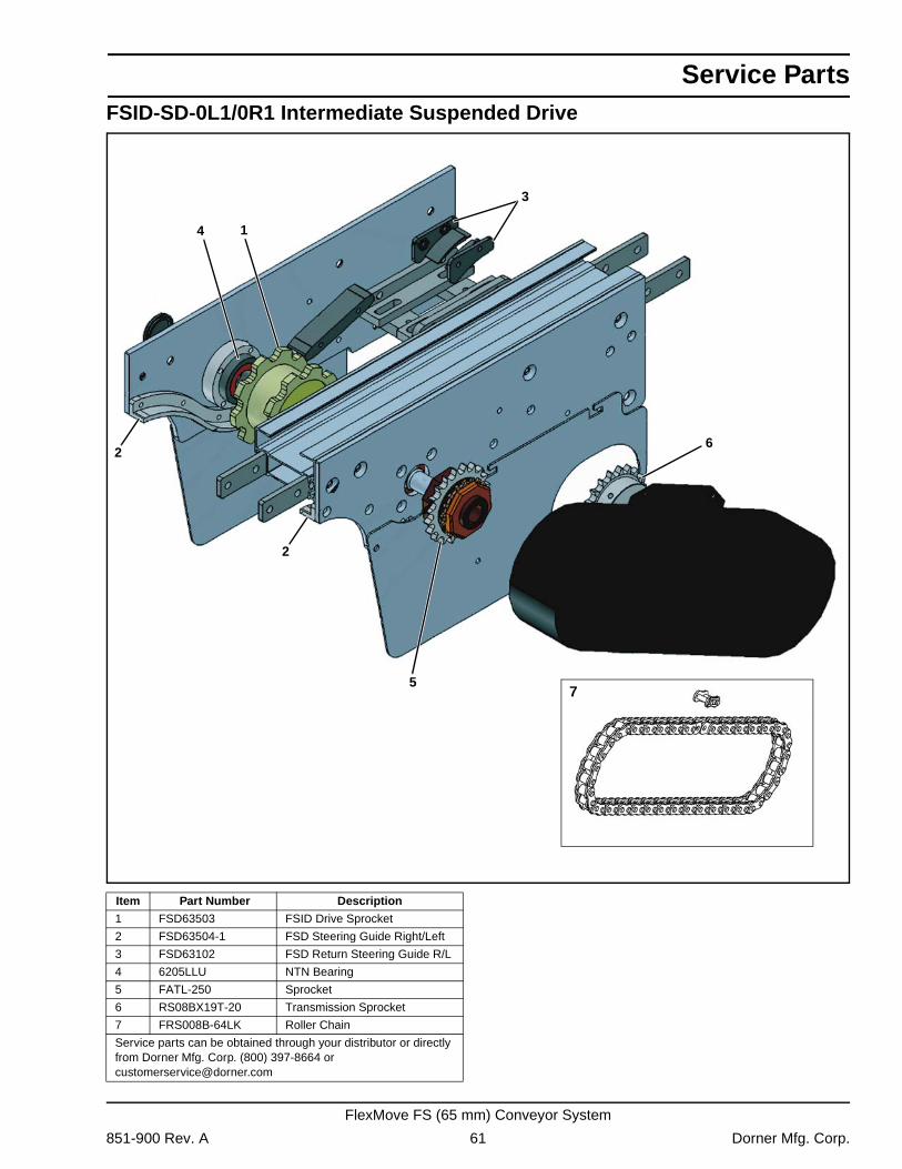
Service Parts
FSID-SD-0L1/0R1 Intermediate Suspended Drive1
2
3
4
75
6
2
Item Part Number Description
1 FSD63503 FSID Drive Sprocket
2 FSD63504-1 FSD Steering Guide Right/Left
3 FSD63102 FSD Return Steering Guide R/L
4 6205LLU NTN Bearing
5 FATL-250 Sprocket
6 RS08BX19T-20 Transmission Sprocket
7 FRS008B-64LK Roller Chain
Service parts can be obtained through your distributor or directly from Dorner Mfg. Corp. (800) 397-8664 or [email protected]
851-900 Rev. A 61 Dorner Mfg. Corp.
FlexMove FS (65 mm) Conveyor System
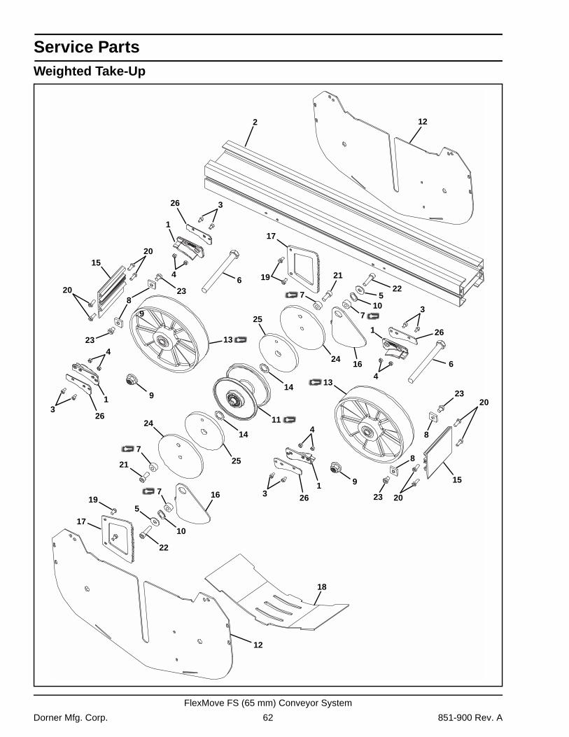
Service Parts
Weighted Take-Up1
2
12
12
1
1
1
3
3
3
3
4
4
4
4
10
6
6
7
7
7
79
8
8
8
9
9
5
510
11
13
1314
15
15
16
16
17
17
19
19
20
20
20
20
21
21
22
2223
23
23
23
18
14
25
24
24
25
26
26
26
26
Dorner Mfg. Corp. 62 851-900 Rev. A
FlexMove FS (65 mm) Conveyor System
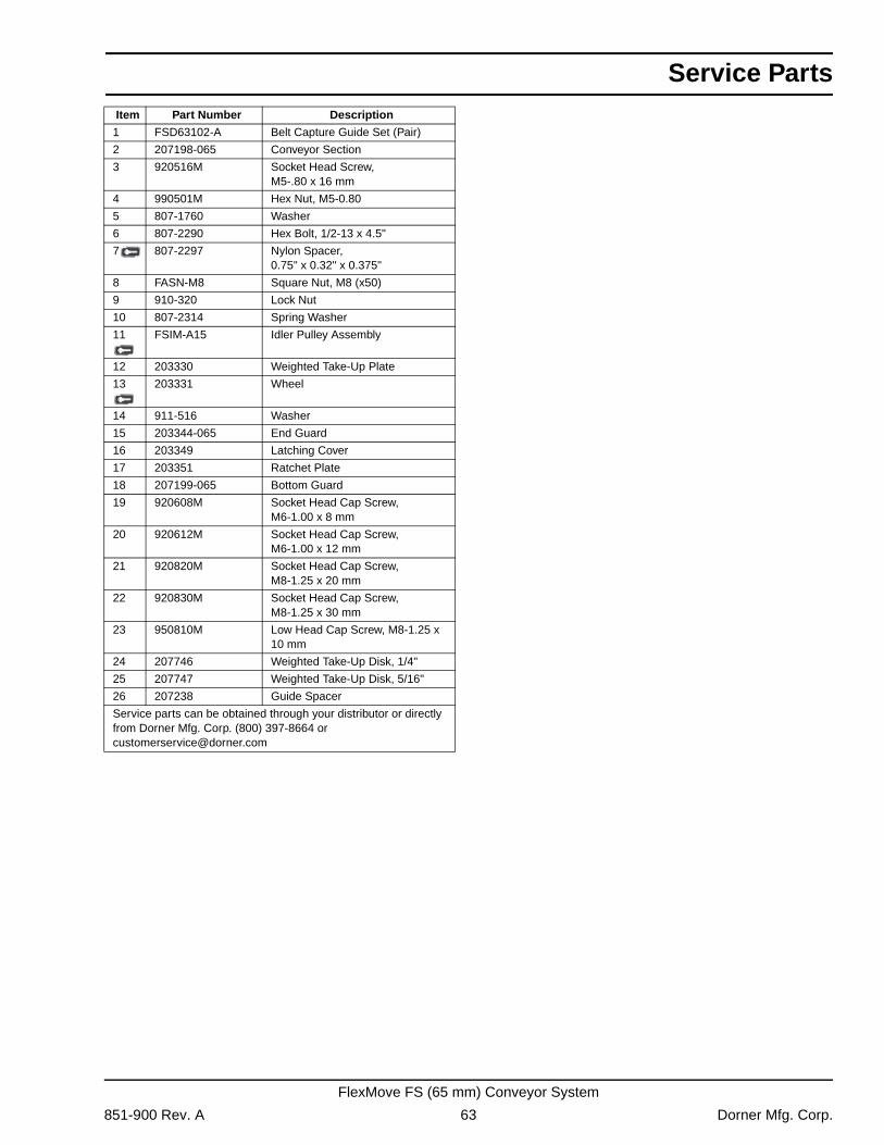
Service Parts
Item Part Number Description1 FSD63102-A Belt Capture Guide Set (Pair)
2 207198-065 Conveyor Section
3 920516M Socket Head Screw,M5-.80 x 16 mm
4 990501M Hex Nut, M5-0.80
5 807-1760 Washer
6 807-2290 Hex Bolt, 1/2-13 x 4.5"
7 807-2297 Nylon Spacer,0.75" x 0.32" x 0.375"
8 FASN-M8 Square Nut, M8 (x50)
9 910-320 Lock Nut
10 807-2314 Spring Washer
11 FSIM-A15 Idler Pulley Assembly
12 203330 Weighted Take-Up Plate
13 203331 Wheel
14 911-516 Washer
15 203344-065 End Guard
16 203349 Latching Cover
17 203351 Ratchet Plate
18 207199-065 Bottom Guard
19 920608M Socket Head Cap Screw,M6-1.00 x 8 mm
20 920612M Socket Head Cap Screw,M6-1.00 x 12 mm
21 920820M Socket Head Cap Screw,M8-1.25 x 20 mm
22 920830M Socket Head Cap Screw, M8-1.25 x 30 mm
23 950810M Low Head Cap Screw, M8-1.25 x 10 mm
24 207746 Weighted Take-Up Disk, 1/4"
25 207747 Weighted Take-Up Disk, 5/16"
26 207238 Guide Spacer
Service parts can be obtained through your distributor or directly from Dorner Mfg. Corp. (800) 397-8664 or [email protected]
851-900 Rev. A 63 Dorner Mfg. Corp.
FlexMove FS (65 mm) Conveyor System
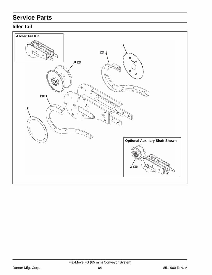
Service Parts
Idler Tail2
1
3
4 Idler Tail Kit
Optional Auxiliary Shaft Shown
3
1
2
Dorner Mfg. Corp. 64 851-900 Rev. A
FlexMove FS (65 mm) Conveyor System
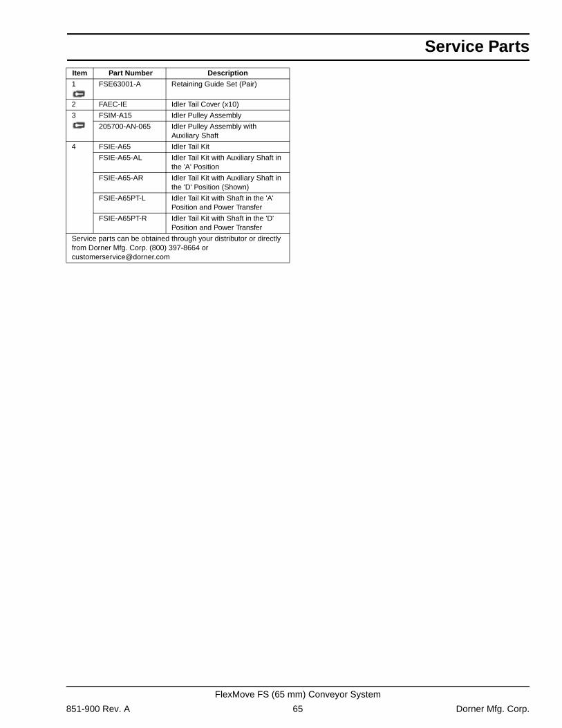
Service Parts
Item Part Number Description1 FSE63001-A Retaining Guide Set (Pair)
2 FAEC-IE Idler Tail Cover (x10)
3 FSIM-A15 Idler Pulley Assembly
205700-AN-065 Idler Pulley Assembly with Auxiliary Shaft
4 FSIE-A65 Idler Tail Kit
FSIE-A65-AL Idler Tail Kit with Auxiliary Shaft in the 'A' Position
FSIE-A65-AR Idler Tail Kit with Auxiliary Shaft in the 'D' Position (Shown)
FSIE-A65PT-L Idler Tail Kit with Shaft in the 'A' Position and Power Transfer
FSIE-A65PT-R Idler Tail Kit with Shaft in the 'D' Position and Power Transfer
Service parts can be obtained through your distributor or directly from Dorner Mfg. Corp. (800) 397-8664 or [email protected]
851-900 Rev. A 65 Dorner Mfg. Corp.
FlexMove FS (65 mm) Conveyor System
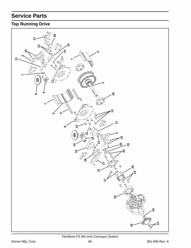
Service Parts
Top Running Drive1
6
2
3
3
5
4
7
8
9
10
10
12
13
13
16
15
18
11
11
12
7
5
13
14
14
15
16
17
20 19
21
22
23
24
25
26
27
28
28
27
29
Dorner Mfg. Corp. 66 851-900 Rev. A
FlexMove FS (65 mm) Conveyor System
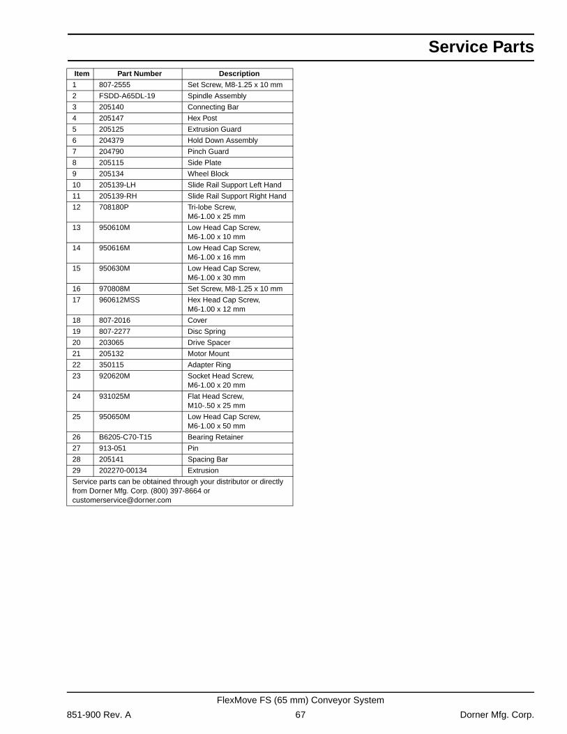
Service Parts
Item Part Number Description1 807-2555 Set Screw, M8-1.25 x 10 mm
2 FSDD-A65DL-19 Spindle Assembly
3 205140 Connecting Bar
4 205147 Hex Post
5 205125 Extrusion Guard
6 204379 Hold Down Assembly
7 204790 Pinch Guard
8 205115 Side Plate
9 205134 Wheel Block
10 205139-LH Slide Rail Support Left Hand
11 205139-RH Slide Rail Support Right Hand
12 708180P Tri-lobe Screw,M6-1.00 x 25 mm
13 950610M Low Head Cap Screw,M6-1.00 x 10 mm
14 950616M Low Head Cap Screw,M6-1.00 x 16 mm
15 950630M Low Head Cap Screw,M6-1.00 x 30 mm
16 970808M Set Screw, M8-1.25 x 10 mm
17 960612MSS Hex Head Cap Screw,M6-1.00 x 12 mm
18 807-2016 Cover
19 807-2277 Disc Spring
20 203065 Drive Spacer
21 205132 Motor Mount
22 350115 Adapter Ring
23 920620M Socket Head Screw,M6-1.00 x 20 mm
24 931025M Flat Head Screw,M10-.50 x 25 mm
25 950650M Low Head Cap Screw,M6-1.00 x 50 mm
26 B6205-C70-T15 Bearing Retainer
27 913-051 Pin
28 205141 Spacing Bar
29 202270-00134 Extrusion
Service parts can be obtained through your distributor or directly from Dorner Mfg. Corp. (800) 397-8664 or [email protected]
851-900 Rev. A 67 Dorner Mfg. Corp.
FlexMove FS (65 mm) Conveyor System
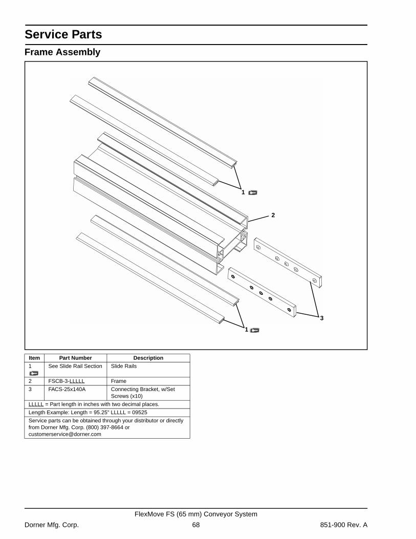
Service Parts
Frame Assembly1
3
1
2
Item Part Number Description
1 See Slide Rail Section Slide Rails
2 FSCB-3-LLLLL Frame
3 FACS-25x140A Connecting Bracket, w/Set Screws (x10)
LLLLL = Part length in inches with two decimal places.
Length Example: Length = 95.25" LLLLL = 09525
Service parts can be obtained through your distributor or directly from Dorner Mfg. Corp. (800) 397-8664 or [email protected]
Dorner Mfg. Corp. 68 851-900 Rev. A
FlexMove FS (65 mm) Conveyor System
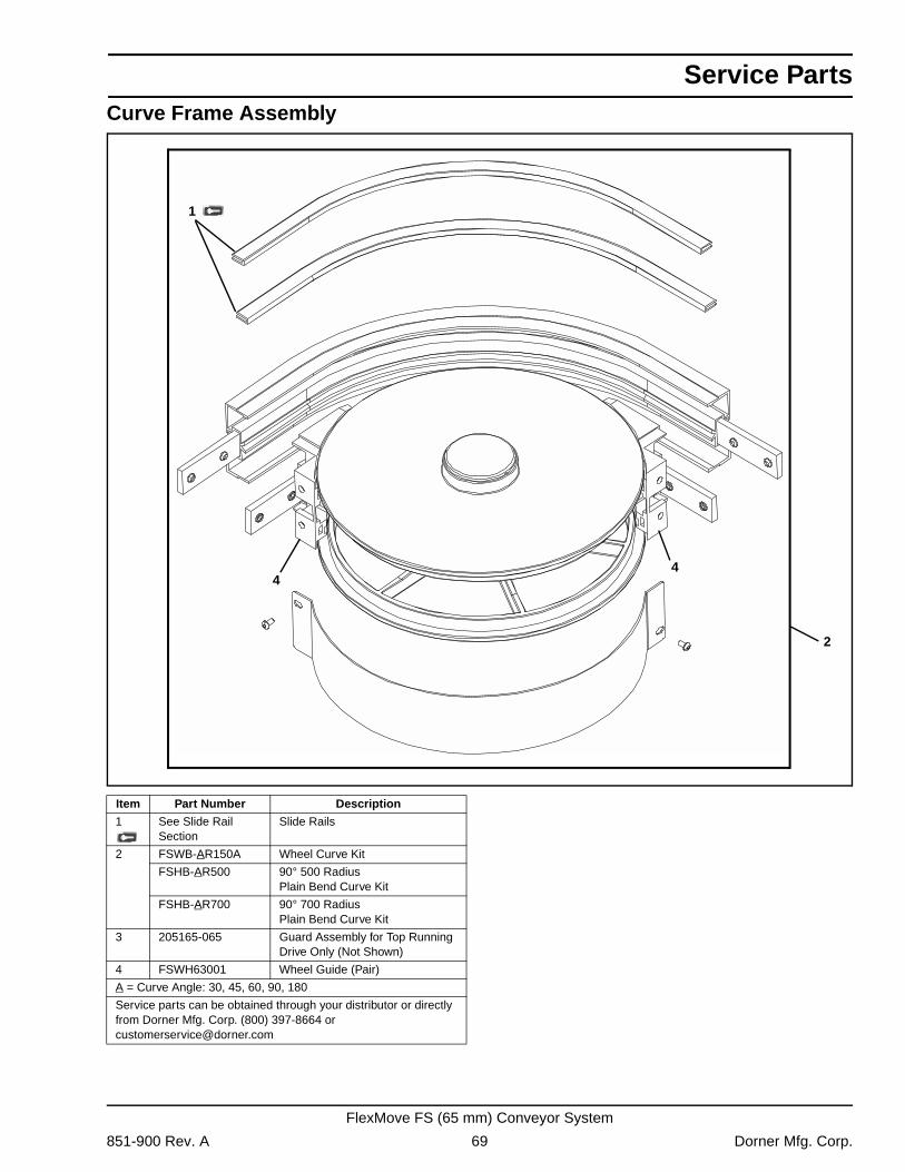
Service Parts
Curve Frame Assembly1
2
44
Item Part Number Description
1 See Slide Rail Section
Slide Rails
2 FSWB-AR150A Wheel Curve Kit
FSHB-AR500 90° 500 RadiusPlain Bend Curve Kit
FSHB-AR700 90° 700 RadiusPlain Bend Curve Kit
3 205165-065 Guard Assembly for Top Running Drive Only (Not Shown)
4 FSWH63001 Wheel Guide (Pair)
A = Curve Angle: 30, 45, 60, 90, 180
Service parts can be obtained through your distributor or directly from Dorner Mfg. Corp. (800) 397-8664 or [email protected]
851-900 Rev. A 69 Dorner Mfg. Corp.
FlexMove FS (65 mm) Conveyor System
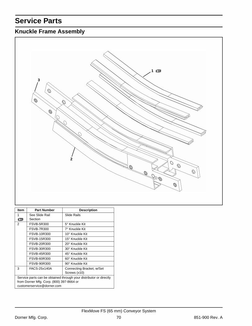
Service Parts
Knuckle Frame Assembly2
1
3
Item Part Number Description
1 See Slide Rail Section
Slide Rails
2 FSVB-5R300 5° Knuckle Kit
FSVB-7R300 7° Knuckle Kit
FSVB-10R300 10° Knuckle Kit
FSVB-15R300 15° Knuckle Kit
FSVB-20R300 20° Knuckle Kit
FSVB-30R300 30° Knuckle Kit
FSVB-45R300 45° Knuckle Kit
FSVB-60R300 60° Knuckle Kit
FSVB-90R300 90° Knuckle Kit
3 FACS-25x140A Connecting Bracket, w/Set Screws (x10)
Service parts can be obtained through your distributor or directly from Dorner Mfg. Corp. (800) 397-8664 or [email protected]
Dorner Mfg. Corp. 70 851-900 Rev. A
FlexMove FS (65 mm) Conveyor System
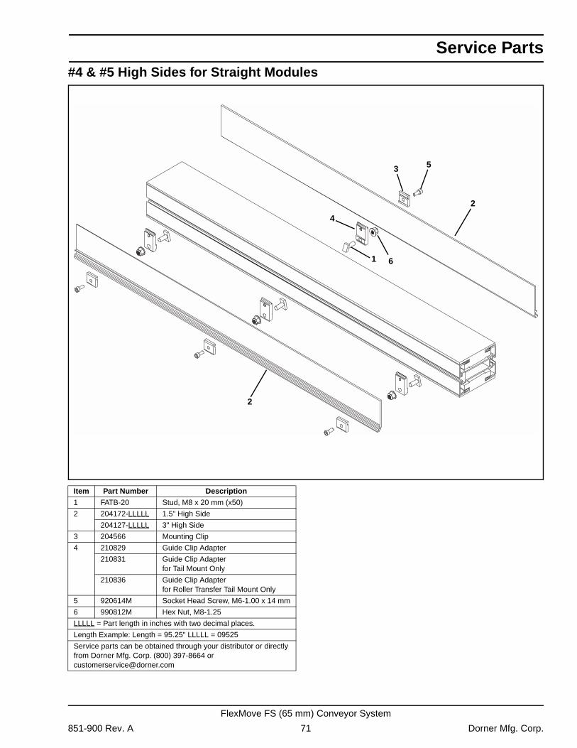
Service Parts
#4 & #5 High Sides for Straight Modules1
5
4
3
2
6
2
Item Part Number Description
1 FATB-20 Stud, M8 x 20 mm (x50)
2 204172-LLLLL 1.5" High Side
204127-LLLLL 3" High Side
3 204566 Mounting Clip
4 210829 Guide Clip Adapter
210831 Guide Clip Adapter for Tail Mount Only
210836 Guide Clip Adapter for Roller Transfer Tail Mount Only
5 920614M Socket Head Screw, M6-1.00 x 14 mm
6 990812M Hex Nut, M8-1.25
LLLLL = Part length in inches with two decimal places.
Length Example: Length = 95.25" LLLLL = 09525
Service parts can be obtained through your distributor or directly from Dorner Mfg. Corp. (800) 397-8664 or [email protected]
851-900 Rev. A 71 Dorner Mfg. Corp.
FlexMove FS (65 mm) Conveyor System
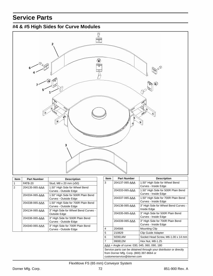
Service Parts
#4 & #5 High Sides for Curve Modules64
3
5
7
2
1
Item Part Number Description
1 FATB-20 Stud, M8 x 20 mm (x50)
2 204135-065-AAA 1.50" High Side for Wheel Bend Curves - Outside Edge
204334-065-AAA 1.50" High Side for 500R Plain Bend Curves - Outside Edge
204338-065-AAA 1.50" High Side for 700R Plain Bend Curves - Outside Edge
204134-065-AAA 3" High Side for Wheel Bend Curves - Outside Edge
204336-065-AAA 3" High Side for 500R Plain Bend Curves - Outside Edge
204340-065-AAA 3" High Side for 700R Plain Bend Curves - Outside Edge
3 204137-065-AAA 1.50" High Side for Wheel Bend Curves - Inside Edge
204333-065-AAA 1.50" High Side for 500R Plain Bend Curves - Inside Edge
204337-065-AAA 1.50" High Side for 700R Plain Bend Curves - Inside Edge
204136-065-AAA 3" High Side for Wheel Bend Curves - Inside Edge
204335-065-AAA 3" High Side for 500R Plain Bend Curves - Inside Edge
204339-065-AAA 3" High Side for 700R Plain Bend Curves - Inside Edge
4 204566 Mounting Clip
5 210829 Clip Guide Adapter
6 920614M Socket Head Screw, M6-1.00 x 14 mm
7 990812M Hex Nut, M8-1.25
AAA = Angle of curve: 030, 045, 060, 090, 180
Service parts can be obtained through your distributor or directly from Dorner Mfg. Corp. (800) 397-8664 or [email protected]
Item Part Number Description
Dorner Mfg. Corp. 72 851-900 Rev. A
FlexMove FS (65 mm) Conveyor System
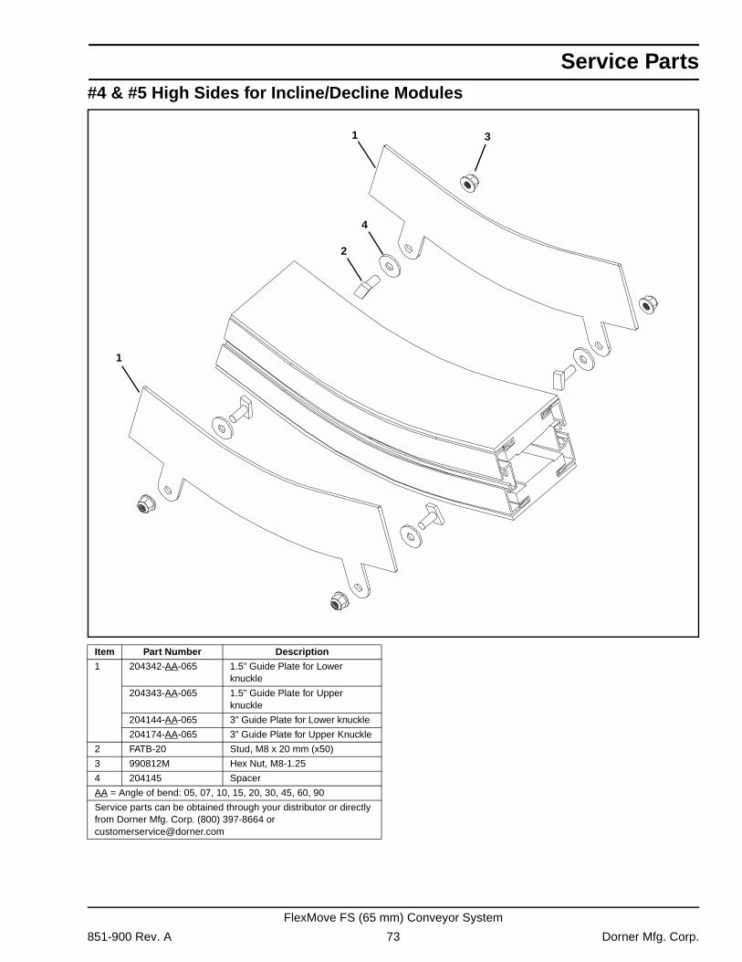
Service Parts
#4 & #5 High Sides for Incline/Decline Modules4
1
2
31
Item Part Number Description
1 204342-AA-065 1.5” Guide Plate for Lower knuckle
204343-AA-065 1.5” Guide Plate for Upper knuckle
204144-AA-065 3” Guide Plate for Lower knuckle
204174-AA-065 3” Guide Plate for Upper Knuckle
2 FATB-20 Stud, M8 x 20 mm (x50)
3 990812M Hex Nut, M8-1.25
4 204145 Spacer
AA = Angle of bend: 05, 07, 10, 15, 20, 30, 45, 60, 90
Service parts can be obtained through your distributor or directly from Dorner Mfg. Corp. (800) 397-8664 or [email protected]
851-900 Rev. A 73 Dorner Mfg. Corp.
FlexMove FS (65 mm) Conveyor System
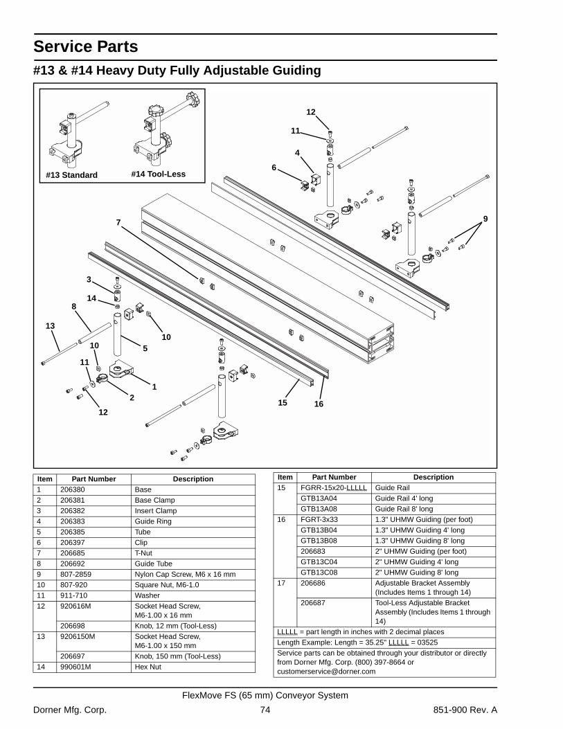
Service Parts
#13 & #14 Heavy Duty Fully Adjustable Guiding3
1
4
5
6
8
9
10
2
7
11
12
13
14
10
11
1215 16
#14 Tool-Less#13 Standard
Item Part Number Description1 206380 Base2 206381 Base Clamp3 206382 Insert Clamp4 206383 Guide Ring5 206385 Tube6 206397 Clip7 206685 T-Nut8 206692 Guide Tube9 807-2859 Nylon Cap Screw, M6 x 16 mm10 807-920 Square Nut, M6-1.011 911-710 Washer12 920616M Socket Head Screw,
M6-1.00 x 16 mm206698 Knob, 12 mm (Tool-Less)
13 9206150M Socket Head Screw, M6-1.00 x 150 mm
206697 Knob, 150 mm (Tool-Less)14 990601M Hex Nut
15 FGRR-15x20-LLLLL Guide RailGTB13A04 Guide Rail 4' longGTB13A08 Guide Rail 8' long
16 FGRT-3x33 1.3" UHMW Guiding (per foot)GTB13B04 1.3" UHMW Guiding 4' longGTB13B08 1.3" UHMW Guiding 8' long206683 2" UHMW Guiding (per foot)GTB13C04 2" UHMW Guiding 4' longGTB13C08 2" UHMW Guiding 8' long
17 206686 Adjustable Bracket Assembly (Includes Items 1 through 14)
206687 Tool-Less Adjustable Bracket Assembly (Includes Items 1 through 14)
LLLLL = part length in inches with 2 decimal placesLength Example: Length = 35.25" LLLLL = 03525Service parts can be obtained through your distributor or directly from Dorner Mfg. Corp. (800) 397-8664 or [email protected]
Item Part Number Description
Dorner Mfg. Corp. 74 851-900 Rev. A
FlexMove FS (65 mm) Conveyor System
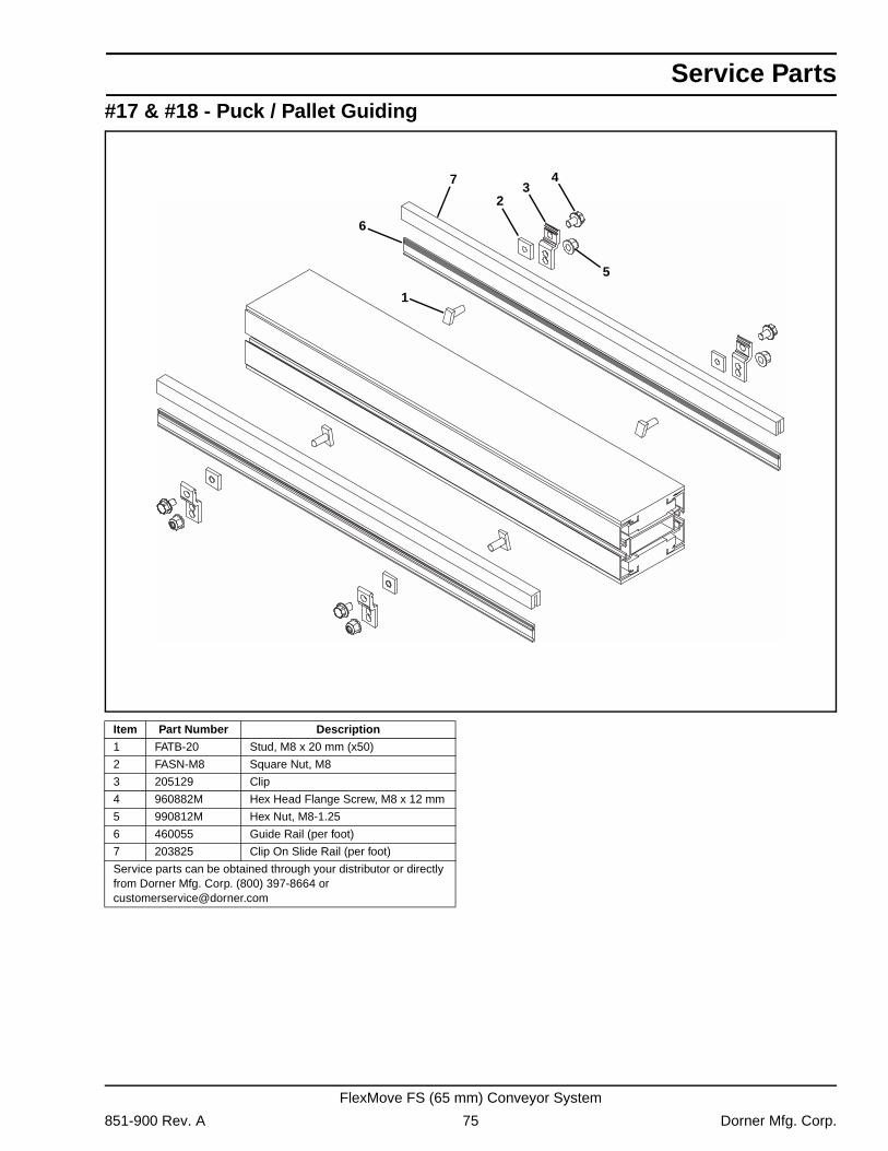
Service Parts
#17 & #18 - Puck / Pallet Guiding4
1
23
5
7
6
Item Part Number Description
1 FATB-20 Stud, M8 x 20 mm (x50)
2 FASN-M8 Square Nut, M8
3 205129 Clip
4 960882M Hex Head Flange Screw, M8 x 12 mm
5 990812M Hex Nut, M8-1.25
6 460055 Guide Rail (per foot)
7 203825 Clip On Slide Rail (per foot)
Service parts can be obtained through your distributor or directly from Dorner Mfg. Corp. (800) 397-8664 or [email protected]
851-900 Rev. A 75 Dorner Mfg. Corp.
FlexMove FS (65 mm) Conveyor System
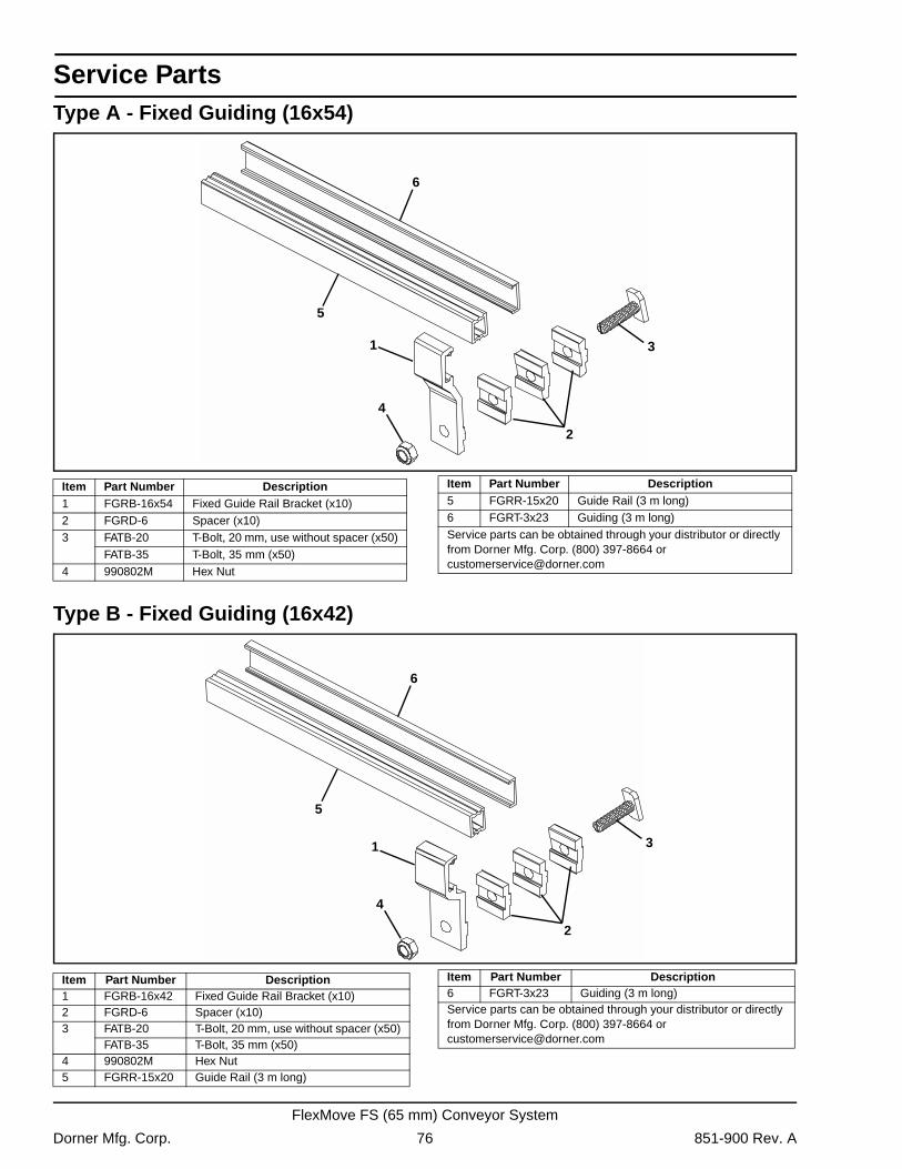
Service Parts
Type A - Fixed Guiding (16x54)Type B - Fixed Guiding (16x42)
4
1
2
3
5
6
Item Part Number Description1 FGRB-16x54 Fixed Guide Rail Bracket (x10)2 FGRD-6 Spacer (x10)3 FATB-20 T-Bolt, 20 mm, use without spacer (x50)
FATB-35 T-Bolt, 35 mm (x50)4 990802M Hex Nut
5 FGRR-15x20 Guide Rail (3 m long)6 FGRT-3x23 Guiding (3 m long)Service parts can be obtained through your distributor or directly from Dorner Mfg. Corp. (800) 397-8664 or [email protected]
Item Part Number Description
4
1
2
3
5
6
Item Part Number Description1 FGRB-16x42 Fixed Guide Rail Bracket (x10)2 FGRD-6 Spacer (x10)3 FATB-20 T-Bolt, 20 mm, use without spacer (x50)
FATB-35 T-Bolt, 35 mm (x50)4 990802M Hex Nut5 FGRR-15x20 Guide Rail (3 m long)
6 FGRT-3x23 Guiding (3 m long)Service parts can be obtained through your distributor or directly from Dorner Mfg. Corp. (800) 397-8664 or [email protected]
Item Part Number Description
Dorner Mfg. Corp. 76 851-900 Rev. A
FlexMove FS (65 mm) Conveyor System
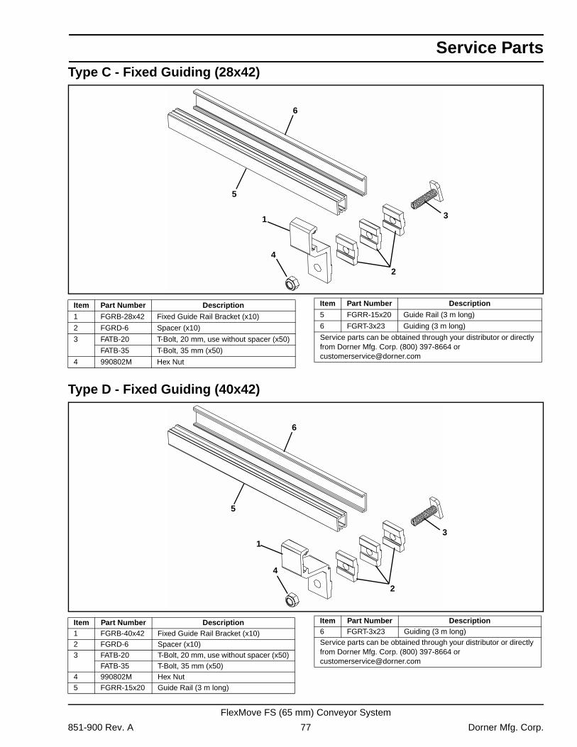
Service Parts
Type C - Fixed Guiding (28x42)Type D - Fixed Guiding (40x42)
4
1
2
3
5
6
Item Part Number Description
1 FGRB-28x42 Fixed Guide Rail Bracket (x10)
2 FGRD-6 Spacer (x10)
3 FATB-20 T-Bolt, 20 mm, use without spacer (x50)
FATB-35 T-Bolt, 35 mm (x50)
4 990802M Hex Nut
5 FGRR-15x20 Guide Rail (3 m long)
6 FGRT-3x23 Guiding (3 m long)
Service parts can be obtained through your distributor or directly from Dorner Mfg. Corp. (800) 397-8664 or [email protected]
Item Part Number Description
4
1
2
3
5
6
Item Part Number Description1 FGRB-40x42 Fixed Guide Rail Bracket (x10)2 FGRD-6 Spacer (x10)3 FATB-20 T-Bolt, 20 mm, use without spacer (x50)
FATB-35 T-Bolt, 35 mm (x50)4 990802M Hex Nut5 FGRR-15x20 Guide Rail (3 m long)
6 FGRT-3x23 Guiding (3 m long)Service parts can be obtained through your distributor or directly from Dorner Mfg. Corp. (800) 397-8664 or [email protected]
Item Part Number Description
851-900 Rev. A 77 Dorner Mfg. Corp.
FlexMove FS (65 mm) Conveyor System
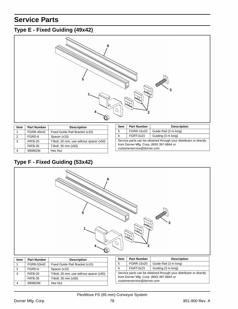
Service Parts
Type E - Fixed Guiding (49x42)Type F - Fixed Guiding (53x42)
4
1
2
3
5
6
Item Part Number Description
1 FGRB-49x42 Fixed Guide Rail Bracket (x10)
2 FGRD-6 Spacer (x10)
3 FATB-20 T-Bolt, 20 mm, use without spacer (x50)
FATB-35 T-Bolt, 35 mm (x50)
4 990802M Hex Nut
5 FGRR-15x20 Guide Rail (3 m long)
6 FGRT-3x23 Guiding (3 m long)
Service parts can be obtained through your distributor or directly from Dorner Mfg. Corp. (800) 397-8664 or [email protected]
Item Part Number Description
4
1
2
3
5
6
Item Part Number Description
1 FGRB-53x42 Fixed Guide Rail Bracket (x10)
2 FGRD-6 Spacer (x10)
3 FATB-20 T-Bolt, 20 mm, use without spacer (x50)
FATB-35 T-Bolt, 35 mm (x50)
4 990802M Hex Nut
5 FGRR-15x20 Guide Rail (3 m long)
6 FGRT-3x23 Guiding (3 m long)
Service parts can be obtained through your distributor or directly from Dorner Mfg. Corp. (800) 397-8664 or [email protected]
Item Part Number Description
Dorner Mfg. Corp. 78 851-900 Rev. A
FlexMove FS (65 mm) Conveyor System
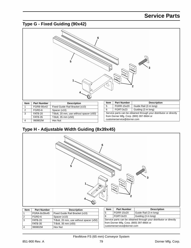
Service Parts
Type G - Fixed Guiding (90x42)Type H - Adjustable Width Guiding (8x39x45)
4
1
2
3
5
6
Item Part Number Description1 FGRB-90x42 Fixed Guide Rail Bracket (x10)2 FGRD-6 Spacer (x10)3 FATB-20 T-Bolt, 20 mm, use without spacer (x50)
FATB-35 T-Bolt, 35 mm (x50)4 990802M Hex Nut
5 FGRR-15x20 Guide Rail (3 m long)6 FGRT-3x23 Guiding (3 m long)Service parts can be obtained through your distributor or directly from Dorner Mfg. Corp. (800) 397-8664 or [email protected]
Item Part Number Description
4
1
2
3
5
6
Item Part Number Description1 FGRA-8x39x45 Fixed Guide Rail Bracket (x10)2 FGRD-6 Spacer (x10)3 FATB-20 T-Bolt, 20 mm, use without spacer (x50)
FATB-35 T-Bolt, 35 mm (x50)4 990802M Hex Nut
5 FGRR-15x20 Guide Rail (3 m long)6 FGRT-3x23 Guiding (3 m long)Service parts can be obtained through your distributor or directly from Dorner Mfg. Corp. (800) 397-8664 or [email protected]
Item Part Number Description
851-900 Rev. A 79 Dorner Mfg. Corp.
FlexMove FS (65 mm) Conveyor System
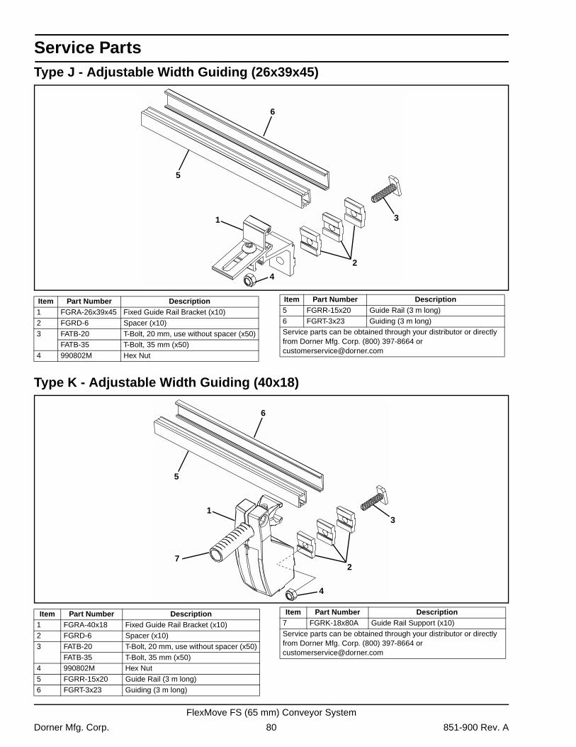
Service Parts
Type J - Adjustable Width Guiding (26x39x45)Type K - Adjustable Width Guiding (40x18)
4
1
2
3
5
6
Item Part Number Description1 FGRA-26x39x45 Fixed Guide Rail Bracket (x10)2 FGRD-6 Spacer (x10)3 FATB-20 T-Bolt, 20 mm, use without spacer (x50)
FATB-35 T-Bolt, 35 mm (x50)4 990802M Hex Nut
5 FGRR-15x20 Guide Rail (3 m long)6 FGRT-3x23 Guiding (3 m long)Service parts can be obtained through your distributor or directly from Dorner Mfg. Corp. (800) 397-8664 or [email protected]
Item Part Number Description
4
1
2
3
5
6
7
Item Part Number Description1 FGRA-40x18 Fixed Guide Rail Bracket (x10)2 FGRD-6 Spacer (x10)3 FATB-20 T-Bolt, 20 mm, use without spacer (x50)
FATB-35 T-Bolt, 35 mm (x50)4 990802M Hex Nut5 FGRR-15x20 Guide Rail (3 m long)6 FGRT-3x23 Guiding (3 m long)
7 FGRK-18x80A Guide Rail Support (x10)Service parts can be obtained through your distributor or directly from Dorner Mfg. Corp. (800) 397-8664 or [email protected]
Item Part Number Description
Dorner Mfg. Corp. 80 851-900 Rev. A
FlexMove FS (65 mm) Conveyor System
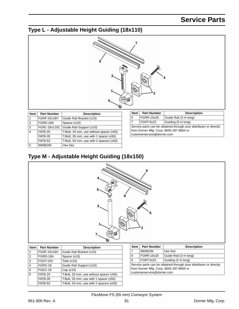
Service Parts
Type L - Adjustable Height Guiding (18x110)Type M - Adjustable Height Guiding (18x150)
5
2
4
1
3
6
7
Item Part Number Description1 FGRF-42x18V Guide Rail Bracket (x10)2 FGRD-18A Spacer (x10)3 FGRL-18x110C Guide Rail Support (x10)4 FATB-20 T-Bolt, 20 mm, use without spacer (x50)
FATB-35 T-Bolt, 35 mm, use with 1 spacer (x50)FATB-53 T-Bolt, 53 mm, use with 2 spacers (x50)
5 990802M Hex Nut
6 FGRR-15x20 Guide Rail (3 m long)7 FGRT-3x23 Guiding (3 m long)Service parts can be obtained through your distributor or directly from Dorner Mfg. Corp. (800) 397-8664 or [email protected]
Item Part Number Description
7
2
6
1
3
8
5
4
9
Item Part Number Description1 FGRF-42x18V Guide Rail Bracket (x10)2 FGRD-18A Spacer (x10)3 FGDT-150 Tube (x10)4 FGRS-18 Guide Rail Support (x10)5 FGEC-18 Cap (x10)6 FATB-20 T-Bolt, 20 mm, use without spacer (x50)
FATB-35 T-Bolt, 35 mm, use with 1 spacer (x50)FATB-53 T-Bolt, 53 mm, use with 2 spacers (x50)
7 990802M Hex Nut8 FGRR-15x20 Guide Rail (3 m long)9 FGRT-3x23 Guiding (3 m long)Service parts can be obtained through your distributor or directly from Dorner Mfg. Corp. (800) 397-8664 or [email protected]
Item Part Number Description
851-900 Rev. A 81 Dorner Mfg. Corp.
FlexMove FS (65 mm) Conveyor System
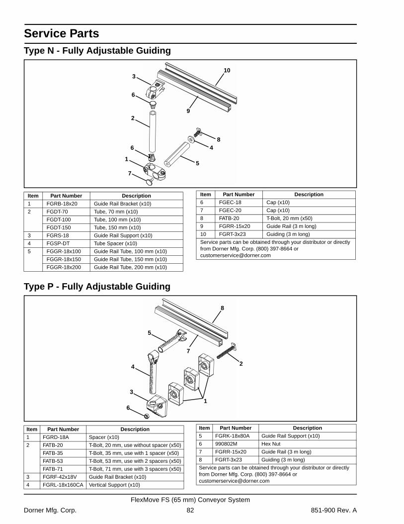
Service Parts
Type N - Fully Adjustable GuidingType P - Fully Adjustable Guiding
7
48
1
2
6
6
3
9
10
15
Item Part Number Description
1 FGRB-18x20 Guide Rail Bracket (x10)
2 FGDT-70 Tube, 70 mm (x10)
FGDT-100 Tube, 100 mm (x10)
FGDT-150 Tube, 150 mm (x10)
3 FGRS-18 Guide Rail Support (x10)
4 FGSP-DT Tube Spacer (x10)
5 FGGR-18x100 Guide Rail Tube, 100 mm (x10)
FGGR-18x150 Guide Rail Tube, 150 mm (x10)
FGGR-18x200 Guide Rail Tube, 200 mm (x10)
6 FGEC-18 Cap (x10)
7 FGEC-20 Cap (x10)
8 FATB-20 T-Bolt, 20 mm (x50)
9 FGRR-15x20 Guide Rail (3 m long)
10 FGRT-3x23 Guiding (3 m long)
Service parts can be obtained through your distributor or directly from Dorner Mfg. Corp. (800) 397-8664 or [email protected]
Item Part Number Description
61
2
3
4
7
5
8
Item Part Number Description
1 FGRD-18A Spacer (x10)
2 FATB-20 T-Bolt, 20 mm, use without spacer (x50)
FATB-35 T-Bolt, 35 mm, use with 1 spacer (x50)
FATB-53 T-Bolt, 53 mm, use with 2 spacers (x50)
FATB-71 T-Bolt, 71 mm, use with 3 spacers (x50)
3 FGRF-42x18V Guide Rail Bracket (x10)
4 FGRL-18x160CA Vertical Support (x10)
5 FGRK-18x80A Guide Rail Support (x10)
6 990802M Hex Nut
7 FGRR-15x20 Guide Rail (3 m long)
8 FGRT-3x23 Guiding (3 m long)
Service parts can be obtained through your distributor or directly from Dorner Mfg. Corp. (800) 397-8664 or [email protected]
Item Part Number Description
Dorner Mfg. Corp. 82 851-900 Rev. A
FlexMove FS (65 mm) Conveyor System
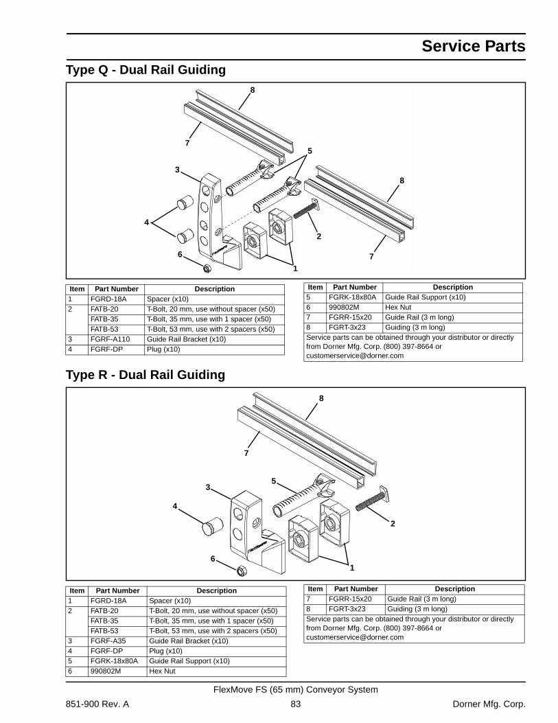
Service Parts
Type Q - Dual Rail GuidingType R - Dual Rail Guiding
6
1
2
3
4
75
8
8
7
Item Part Number Description1 FGRD-18A Spacer (x10)2 FATB-20 T-Bolt, 20 mm, use without spacer (x50)
FATB-35 T-Bolt, 35 mm, use with 1 spacer (x50)FATB-53 T-Bolt, 53 mm, use with 2 spacers (x50)
3 FGRF-A110 Guide Rail Bracket (x10)4 FGRF-DP Plug (x10)
5 FGRK-18x80A Guide Rail Support (x10)6 990802M Hex Nut7 FGRR-15x20 Guide Rail (3 m long)8 FGRT-3x23 Guiding (3 m long)Service parts can be obtained through your distributor or directly from Dorner Mfg. Corp. (800) 397-8664 or [email protected]
Item Part Number Description
61
2
3
4
7
5
8
Item Part Number Description1 FGRD-18A Spacer (x10)2 FATB-20 T-Bolt, 20 mm, use without spacer (x50)
FATB-35 T-Bolt, 35 mm, use with 1 spacer (x50)FATB-53 T-Bolt, 53 mm, use with 2 spacers (x50)
3 FGRF-A35 Guide Rail Bracket (x10)4 FGRF-DP Plug (x10)5 FGRK-18x80A Guide Rail Support (x10)6 990802M Hex Nut
7 FGRR-15x20 Guide Rail (3 m long)8 FGRT-3x23 Guiding (3 m long)Service parts can be obtained through your distributor or directly from Dorner Mfg. Corp. (800) 397-8664 or [email protected]
Item Part Number Description
851-900 Rev. A 83 Dorner Mfg. Corp.
FlexMove FS (65 mm) Conveyor System
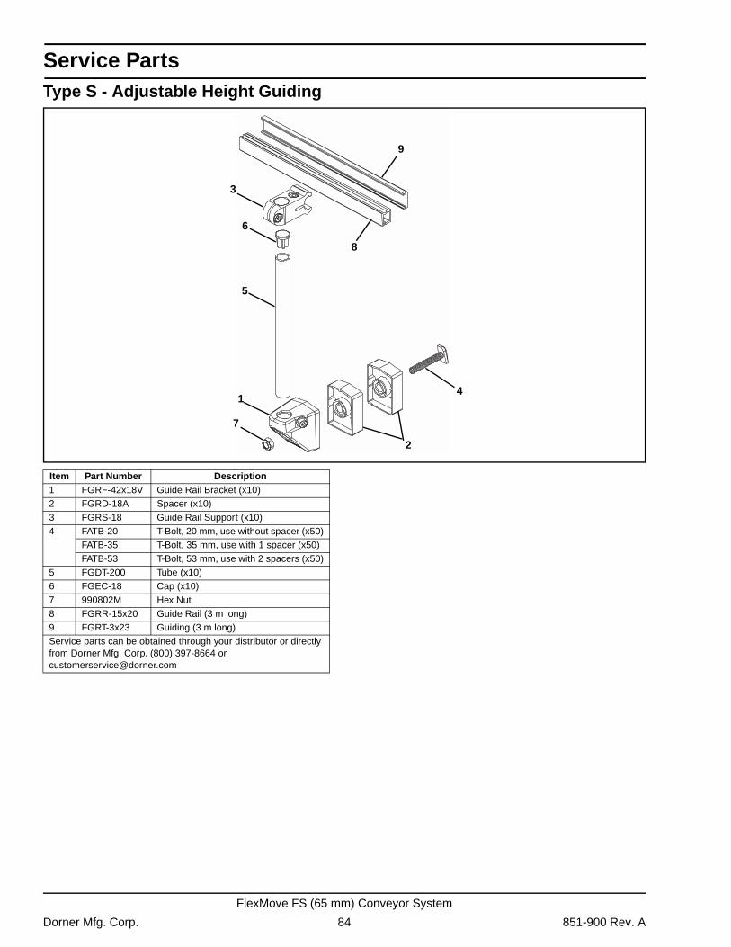
Service Parts
Type S - Adjustable Height Guiding1
2
4
5
7
8
6
9
3
Item Part Number Description1 FGRF-42x18V Guide Rail Bracket (x10)2 FGRD-18A Spacer (x10)3 FGRS-18 Guide Rail Support (x10)4 FATB-20 T-Bolt, 20 mm, use without spacer (x50)
FATB-35 T-Bolt, 35 mm, use with 1 spacer (x50)FATB-53 T-Bolt, 53 mm, use with 2 spacers (x50)
5 FGDT-200 Tube (x10)6 FGEC-18 Cap (x10)7 990802M Hex Nut8 FGRR-15x20 Guide Rail (3 m long)9 FGRT-3x23 Guiding (3 m long)Service parts can be obtained through your distributor or directly from Dorner Mfg. Corp. (800) 397-8664 or [email protected]
Dorner Mfg. Corp. 84 851-900 Rev. A
FlexMove FS (65 mm) Conveyor System
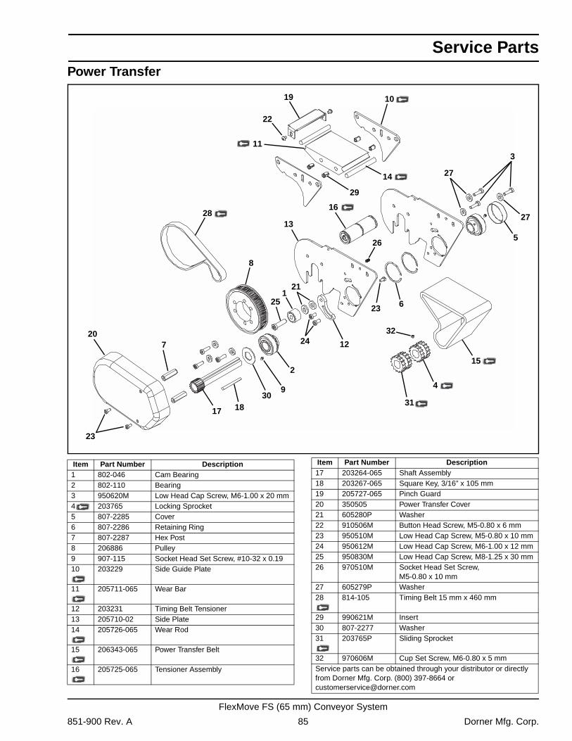
Service Parts
Power Transfer20
14
8
13
11
1
17 18
4
15
3
28
10
6
2
526
16
27
23
19
22
7
2325
21
1224
9
27
29
30
32
31
Item Part Number Description1 802-046 Cam Bearing2 802-110 Bearing3 950620M Low Head Cap Screw, M6-1.00 x 20 mm4 203765 Locking Sprocket5 807-2285 Cover6 807-2286 Retaining Ring7 807-2287 Hex Post8 206886 Pulley9 907-115 Socket Head Set Screw, #10-32 x 0.1910 203229 Side Guide Plate
11 205711-065 Wear Bar
12 203231 Timing Belt Tensioner13 205710-02 Side Plate14 205726-065 Wear Rod
15 206343-065 Power Transfer Belt
16 205725-065 Tensioner Assembly
17 203264-065 Shaft Assembly18 203267-065 Square Key, 3/16” x 105 mm19 205727-065 Pinch Guard20 350505 Power Transfer Cover21 605280P Washer22 910506M Button Head Screw, M5-0.80 x 6 mm23 950510M Low Head Cap Screw, M5-0.80 x 10 mm24 950612M Low Head Cap Screw, M6-1.00 x 12 mm25 950830M Low Head Cap Screw, M8-1.25 x 30 mm26 970510M Socket Head Set Screw,
M5-0.80 x 10 mm27 605279P Washer28 814-105 Timing Belt 15 mm x 460 mm
29 990621M Insert30 807-2277 Washer31 203765P Sliding Sprocket
32 970606M Cup Set Screw, M6-0.80 x 5 mmService parts can be obtained through your distributor or directly from Dorner Mfg. Corp. (800) 397-8664 or [email protected]
Item Part Number Description
851-900 Rev. A 85 Dorner Mfg. Corp.
FlexMove FS (65 mm) Conveyor System
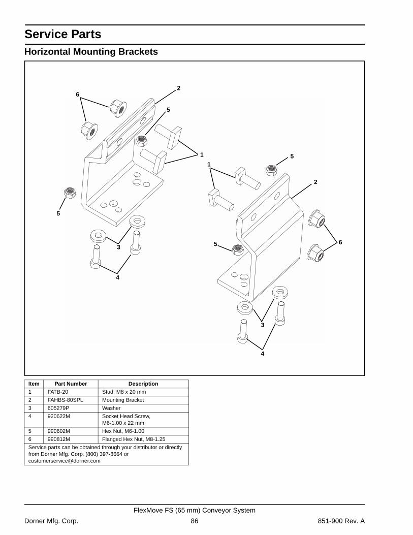
Service Parts
Horizontal Mounting Brackets6
1
2
5
5
5
3
4
1
2
6
3
4
5
Item Part Number Description
1 FATB-20 Stud, M8 x 20 mm
2 FAHBS-80SPL Mounting Bracket
3 605279P Washer
4 920622M Socket Head Screw,M6-1.00 x 22 mm
5 990602M Hex Nut, M6-1.00
6 990812M Flanged Hex Nut, M8-1.25
Service parts can be obtained through your distributor or directly from Dorner Mfg. Corp. (800) 397-8664 or [email protected]
Dorner Mfg. Corp. 86 851-900 Rev. A
FlexMove FS (65 mm) Conveyor System
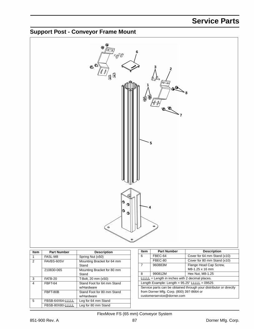
Service Parts
Support Post - Conveyor Frame Mount1
3 2
6
5
4
7
8
Item Part Number Description1 FASL-M8 Spring Nut (x50)2 FAVBS-60SV Mounting Bracket for 64 mm
Stand210830-065 Mounting Bracket for 80 mm
Stand3 FATB-20 T-Bolt, 20 mm (x50)4 FBFT-64 Stand Foot for 64 mm Stand
w/HardwareFBFT-80B Stand Foot for 80 mm Stand
w/Hardware5 FBSB-64X64-LLLLL Leg for 64 mm Stand
FBSB-80X80-LLLLL Leg for 80 mm Stand
6 FBEC-64 Cover for 64 mm Stand (x10)FBEC-80 Cover for 80 mm Stand (x10)
7 960883M Flange Head Cap Screw,M8-1.25 x 16 mm
8 990812M Hex Nut, M8-1.25LLLLL = Length in inches with 2 decimal places.Length Example: Length = 95.25" LLLLL = 09525Service parts can be obtained through your distributor or directly from Dorner Mfg. Corp. (800) 397-8664 or [email protected]
Item Part Number Description
851-900 Rev. A 87 Dorner Mfg. Corp.
FlexMove FS (65 mm) Conveyor System
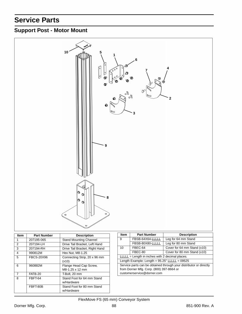
Service Parts
Support Post - Motor Mount6
8
1
3
74
2
510
9
Item Part Number Description1 207195-065 Stand Mounting Channel2 207194-LH Drive Tail Bracket, Left Hand3 207194-RH Drive Tail Bracket, Right Hand4 990812M Hex Nut, M8-1.255 FBCS-20X96 Connecting Strip, 20 x 96 mm
(x10)6 960882M Flange Head Cap Screw,
M8-1.25 x 12 mm7 FATB-20 T-Bolt, 20 mm8 FBFT-64 Stand Foot for 64 mm Stand
w/HardwareFBFT-80B Stand Foot for 80 mm Stand
w/Hardware
9 FBSB-64X64-LLLLL Leg for 64 mm StandFBSB-80X80-LLLLL Leg for 80 mm Stand
10 FBEC-64 Cover for 64 mm Stand (x10)FBEC-80 Cover for 80 mm Stand (x10)
LLLLL = Length in inches with 2 decimal places.Length Example: Length = 95.25" LLLLL = 09525Service parts can be obtained through your distributor or directly from Dorner Mfg. Corp. (800) 397-8664 or [email protected]
Item Part Number Description
Dorner Mfg. Corp. 88 851-900 Rev. A
FlexMove FS (65 mm) Conveyor System
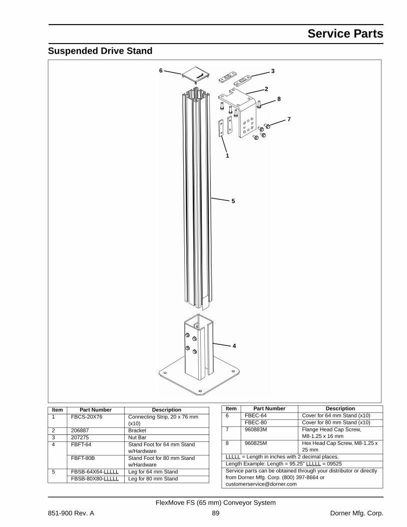
Service Parts
Suspended Drive Stand6
7
8
5
4
2
3
1
Item Part Number Description1 FBCS-20X76 Connecting Strip, 20 x 76 mm
(x10)2 206887 Bracket3 207275 Nut Bar4 FBFT-64 Stand Foot for 64 mm Stand
w/HardwareFBFT-80B Stand Foot for 80 mm Stand
w/Hardware5 FBSB-64X64-LLLLL Leg for 64 mm Stand
FBSB-80X80-LLLLL Leg for 80 mm Stand
6 FBEC-64 Cover for 64 mm Stand (x10)FBEC-80 Cover for 80 mm Stand (x10)
7 960883M Flange Head Cap Screw, M8-1.25 x 16 mm
8 960825M Hex Head Cap Screw, M8-1.25 x 25 mm
LLLLL = Length in inches with 2 decimal places.Length Example: Length = 95.25" LLLLL = 09525Service parts can be obtained through your distributor or directly from Dorner Mfg. Corp. (800) 397-8664 or [email protected]
Item Part Number Description
851-900 Rev. A 89 Dorner Mfg. Corp.
FlexMove FS (65 mm) Conveyor System
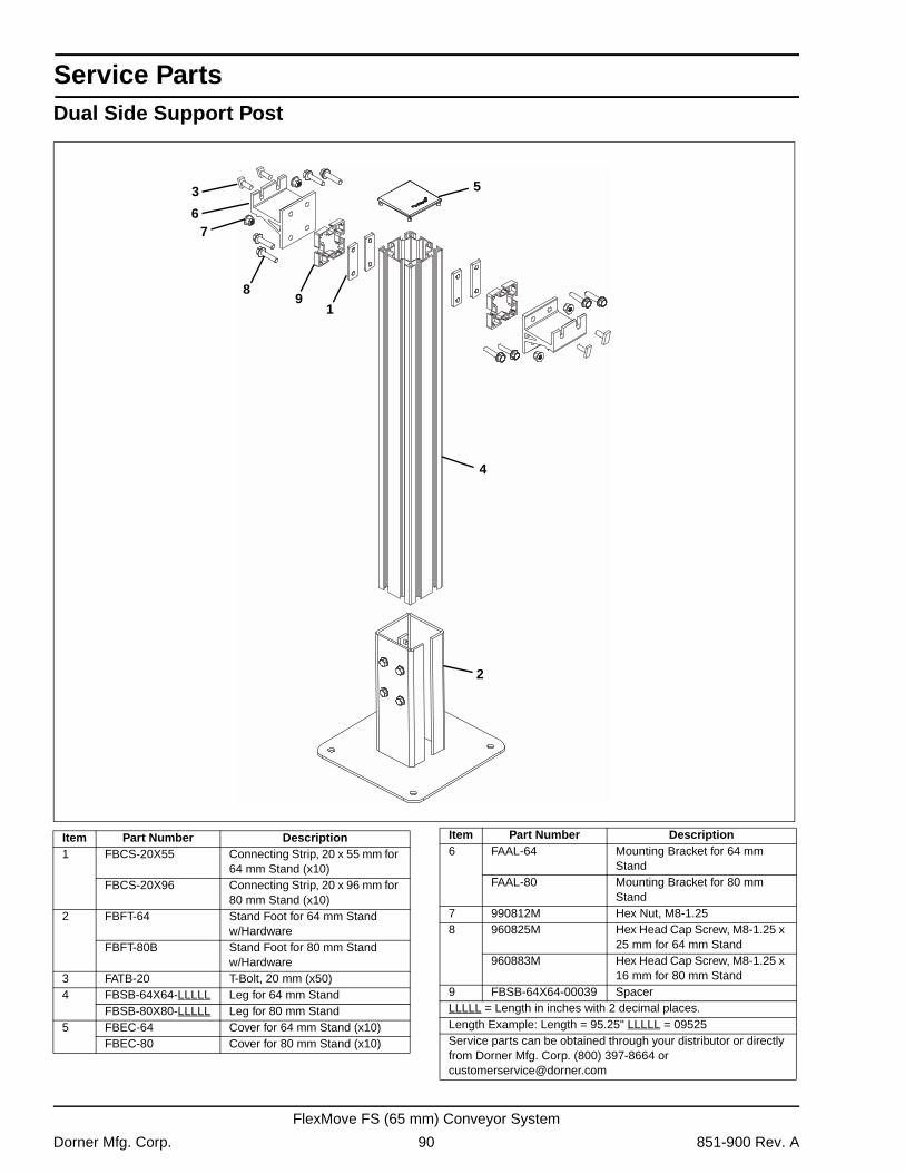
Service Parts
Dual Side Support Post3
67
4
2
8
1
5
9
Item Part Number Description1 FBCS-20X55 Connecting Strip, 20 x 55 mm for
64 mm Stand (x10)FBCS-20X96 Connecting Strip, 20 x 96 mm for
80 mm Stand (x10)2 FBFT-64 Stand Foot for 64 mm Stand
w/HardwareFBFT-80B Stand Foot for 80 mm Stand
w/Hardware3 FATB-20 T-Bolt, 20 mm (x50)4 FBSB-64X64-LLLLL Leg for 64 mm Stand
FBSB-80X80-LLLLL Leg for 80 mm Stand5 FBEC-64 Cover for 64 mm Stand (x10)
FBEC-80 Cover for 80 mm Stand (x10)
6 FAAL-64 Mounting Bracket for 64 mm Stand
FAAL-80 Mounting Bracket for 80 mm Stand
7 990812M Hex Nut, M8-1.258 960825M Hex Head Cap Screw, M8-1.25 x
25 mm for 64 mm Stand960883M Hex Head Cap Screw, M8-1.25 x
16 mm for 80 mm Stand9 FBSB-64X64-00039 SpacerLLLLL = Length in inches with 2 decimal places.Length Example: Length = 95.25" LLLLL = 09525Service parts can be obtained through your distributor or directly from Dorner Mfg. Corp. (800) 397-8664 or [email protected]
Item Part Number Description
Dorner Mfg. Corp. 90 851-900 Rev. A
FlexMove FS (65 mm) Conveyor System
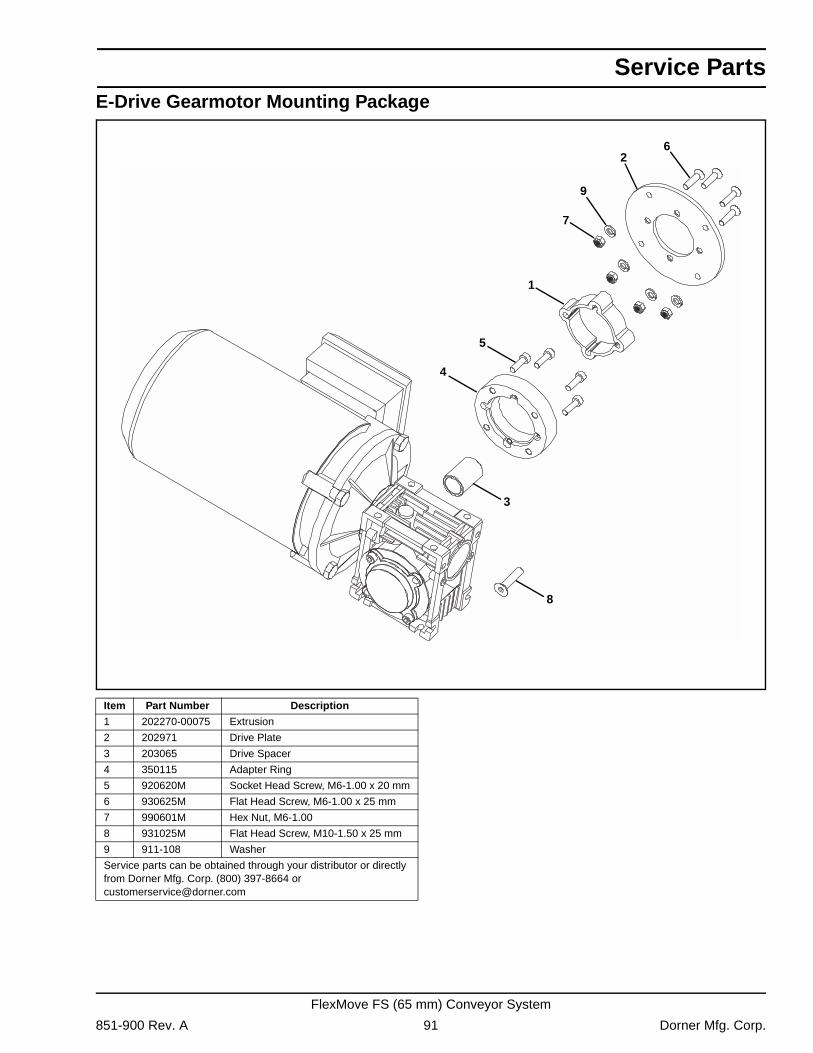
Service Parts
E-Drive Gearmotor Mounting Package1
3
2
8
5
4
7
6
9
Item Part Number Description
1 202270-00075 Extrusion
2 202971 Drive Plate
3 203065 Drive Spacer
4 350115 Adapter Ring
5 920620M Socket Head Screw, M6-1.00 x 20 mm
6 930625M Flat Head Screw, M6-1.00 x 25 mm
7 990601M Hex Nut, M6-1.00
8 931025M Flat Head Screw, M10-1.50 x 25 mm
9 911-108 Washer
Service parts can be obtained through your distributor or directly from Dorner Mfg. Corp. (800) 397-8664 or [email protected]
851-900 Rev. A 91 Dorner Mfg. Corp.
FlexMove FS (65 mm) Conveyor System
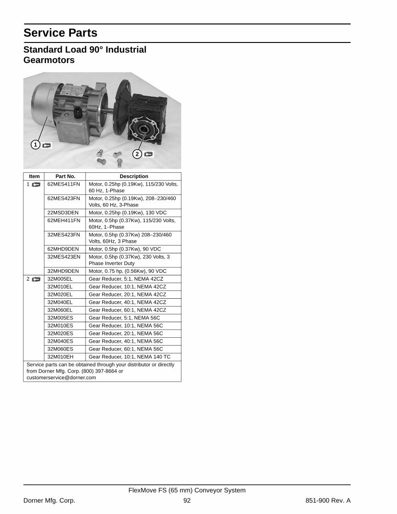
Service Parts
Standard Load 90° Industrial GearmotorsItem Part No. Description
1 62MES411FN Motor, 0.25hp (0.19Kw), 115/230 Volts, 60 Hz, 1-Phase
62MES423FN Motor, 0.25hp (0.19Kw), 208−230/460 Volts, 60 Hz, 3-Phase
22MSD3DEN Motor, 0.25hp (0.19Kw), 130 VDC
62MEH411FN Motor, 0.5hp (0.37Kw), 115/230 Volts, 60Hz, 1−Phase
32MES423FN Motor, 0.5hp (0.37Kw) 208−230/460 Volts, 60Hz, 3 Phase
62MHD9DEN Motor, 0.5hp (0.37Kw), 90 VDC
32MES423EN Motor, 0.5hp (0.37Kw), 230 Volts, 3 Phase Inverter Duty
32MHD9DEN Motor, 0.75 hp, (0.56Kw), 90 VDC
2 32M005EL Gear Reducer, 5:1, NEMA 42CZ
32M010EL Gear Reducer, 10:1, NEMA 42CZ
32M020EL Gear Reducer, 20:1, NEMA 42CZ
32M040EL Gear Reducer, 40:1, NEMA 42CZ
32M060EL Gear Reducer, 60:1, NEMA 42CZ
32M005ES Gear Reducer, 5:1, NEMA 56C
32M010ES Gear Reducer, 10:1, NEMA 56C
32M020ES Gear Reducer, 20:1, NEMA 56C
32M040ES Gear Reducer, 40:1, NEMA 56C
32M060ES Gear Reducer, 60:1, NEMA 56C
32M010EH Gear Reducer, 10:1, NEMA 140 TC
Service parts can be obtained through your distributor or directly from Dorner Mfg. Corp. (800) 397-8664 or [email protected]
1
2
Dorner Mfg. Corp. 92 851-900 Rev. A
FlexMove FS (65 mm) Conveyor System
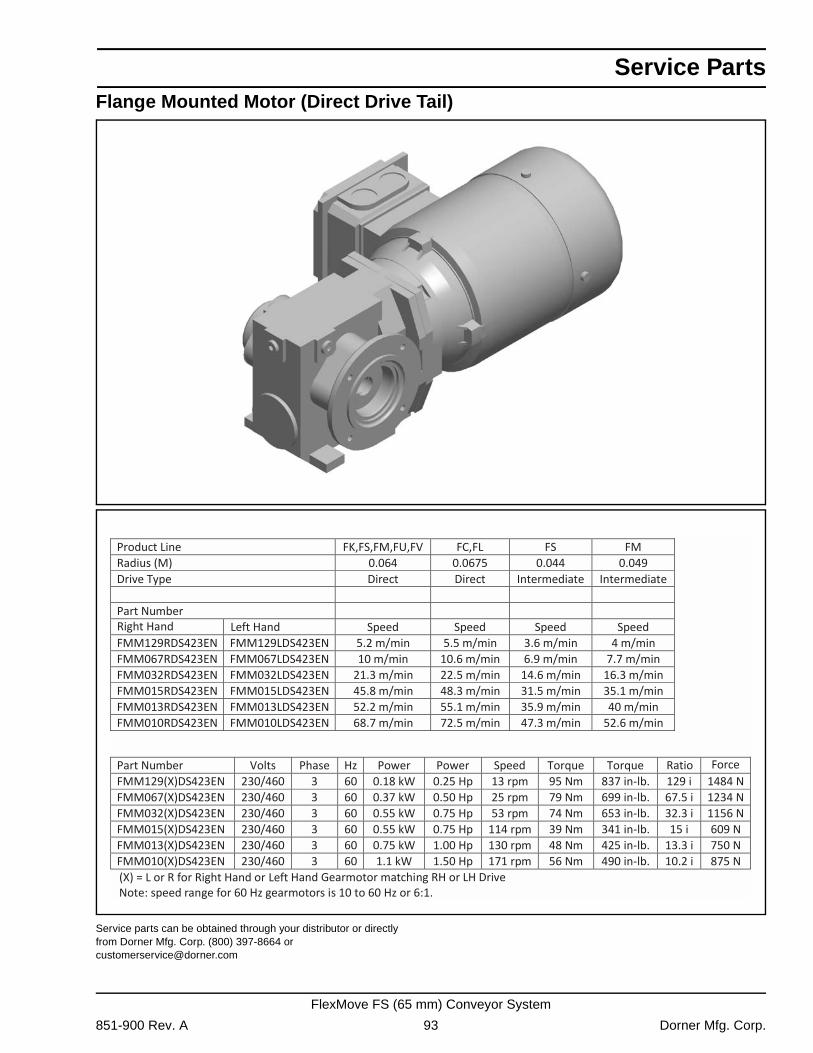
Service Parts
Flange Mounted Motor (Direct Drive Tail)Service parts can be obtained through your distributor or directly from Dorner Mfg. Corp. (800) 397-8664 or [email protected]
Product Line FK,FS,FM,FU,FV FC,FL FS FM Radius (M) 0.064 0.0675 0.044 0.049 Drive Type Direct Direct Intermediate Intermediate
Part Number Speed Speed Speed Speed
FMM129RDS423EN FMM129LDS423EN 5.2 m/min 5.5 m/min 3.6 m/min 4 m/min FMM067RDS423EN FMM067LDS423EN 10 m/min 10.6 m/min 6.9 m/min 7.7 m/min FMM032RDS423EN FMM032LDS423EN 21.3 m/min 22.5 m/min 14.6 m/min 16.3 m/min FMM015RDS423EN FMM015LDS423EN 45.8 m/min 48.3 m/min 31.5 m/min 35.1 m/min FMM013RDS423EN FMM013LDS423EN 52.2 m/min 55.1 m/min 35.9 m/min 40 m/min FMM010RDS423EN FMM010LDS423EN 68.7 m/min 72.5 m/min 47.3 m/min 52.6 m/min
Part Number Volts Phase Hz Power Power Speed Torque Torque FMM129(X)DS423EN 230/460 3 60 0.18 kW 0.25 Hp 13 rpm 95 Nm 837 in-lb. 129 i 1484 N FMM067(X)DS423EN 230/460 3 60 0.37 kW 0.50 Hp 25 rpm 79 Nm 699 in-lb. 67.5 i 1234 N FMM032(X)DS423EN 230/460 3 60 0.55 kW 0.75 Hp 53 rpm 74 Nm 653 in-lb. 32.3 i 1156 N FMM015(X)DS423EN 230/460 3 60 0.55 kW 0.75 Hp 114 rpm 39 Nm 341 in-lb. 15 i 609 N FMM013(X)DS423EN 230/460 3 60 0.75 kW 1.00 Hp 130 rpm 48 Nm 425 in-lb. 13.3 i 750 N FMM010(X)DS423EN 230/460 3 60 1.1 kW 1.50 Hp 171 rpm 56 Nm 490 in-lb. 10.2 i 875 N
Hand Gearmotor matching RH or LH Drive Note: speed range for 60 Hz gearmotors is 10 to 60 Hz or 6:1.
Force
Right Hand
(X) = L or R for Right Hand o
Left Hand
Ratio
Left
851-900 Rev. A 93 Dorner Mfg. Corp.
FlexMove FS (65 mm) Conveyor System
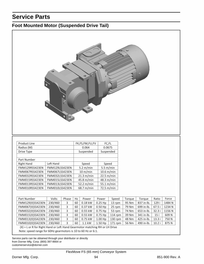
Service Parts
Foot Mounted Motor (Suspended Drive Tail)Service parts can be obtained through your distributor or directly from Dorner Mfg. Corp. (800) 397-8664 or [email protected]
Product Line FK,FS,FM,FU,FV FC,FL Radius (M) 0.064 0.0675 Drive Type Suspended Suspended
Part Number Speed Speed
FMM129RSS423EN FMM129LSS423EN 5.2 m/min 5.5 m/min FMM067RSS423EN FMM067LSS423EN 10 m/min 10.6 m/min FMM032RSS423EN FMM032LSS423EN 21.3 m/min 22.5 m/min FMM015RSS423EN FMM015LSS423EN 45.8 m/min 48.3 m/min FMM013RSS423EN FMM013LSS423EN 52.2 m/min 55.1 m/min FMM010RSS423EN FMM010LSS423EN 68.7 m/min 72.5 m/min
Part Number Volts Phase Hz Power Power Speed Torque Torque FMM129(X)SS423EN 230/460 3 60 0.18 kW 0.25 Hp 13 rpm 95 Nm 837 in-lb. 129 i 1484 N FMM067(X)SS423EN 230/460 3 60 0.37 kW 0.50 Hp 25 rpm 79 Nm 699 in-lb. 67.5 i 1234 N FMM032(X)SS423EN 230/460 3 60 0.55 kW 0.75 Hp 53 rpm 74 Nm 653 in-lb. 32.3 i 1156 N FMM015(X)SS423EN 230/460 3 60 0.55 kW 0.75 Hp 114 rpm 39 Nm 341 in-lb. 15 i 609 N FMM013(X)SS423EN 230/460 3 60 0.75 kW 1.00 Hp 130 rpm 48 Nm 425 in-lb. 13.3 i 750 N FMM010(X)SS423EN 230/460 3 60 1.1 kW 1.50 Hp 171 rpm 56 Nm 490 in-lb. 10.2 i 875 N
Hand Gearmotor matching RH or LH Drive Note: speed range for 60Hz gearmotors is 10 to 60 Hz or 6:1.
nd Right Hand
Force
(X) = L or R for Right Hand o
Dorner Mfg. Corp. 94 851-900 Rev. A
FlexMove FS (65 mm) Conveyor System
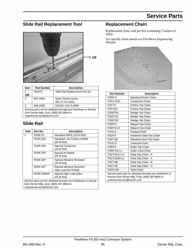
Service Parts
Slide Rail Replacement ToolSlide Rail
Replacement ChainReplacement chain sold per box containing 5 meters of chain.For specific chain details see FlexMove Engineering Manual.
Item Part Number Description
1 203475 Slide Rail Replacement Tool Kit
2 807-2694 Nylon Socket Screw, M5 x 6 mm (x50)
3 896-1008 Drill Bit, #18, 0.1695"
Service parts can be obtained through your distributor or directly from Dorner Mfg. Corp. (800) 397-8664 or [email protected]
Item Part No. Description
1 FASR-25 Standard HDPE (25 M Roll)
FASR-25U Standard Low Friction UHMW(25 M Roll)
FASR-25A Special Conductive(25 M Roll)
FASR-25X Special HI Speed(25 M Roll)
FASR-25P Special Abrasive Resistant(25 M Roll)
FASR-25T Special Abrasive Resistant, High Load (25 M Roll)
FASR-25MDS Special High Load Nylon(25 M Roll)
Service parts can be obtained through your distributor or directly from Dorner Mfg. Corp. (800) 397-8664 or [email protected]
3
2
1
Part Number Description
FSPC-5 Standard Plastic Chain
FSPC-5CD Conductive Chain
FSFT-5 Friction Top Chain
FSFT-5C Friction Top Chain
FSWT-5A Wedge Top Chain
FSWT-5C Wedge Top Chain
FSWT-5D Wedge Top Chain
FSMT-5 Magnet Top Chain
FSMT-5-L# Magnet Top Chain
FSFK-5 Flocked Chain
FSST-5 Hardened Steel Top Chain
FSST-5S Stainless Steel Top Chain
FSUC-5 Universal Chain
FSRT-5 Roller Top Chain
FSRC-5A-L# Roller Cleat Chain
FSCT-5A17-L# Cleat Top Chain - A
FSCT-5A30-L# Cleat Top Chain - A
FSCT-5B Cleat Top Chain - B
FSCT-5C Cleat Top Chain - C
FSPC-5M Twist Chain
Service parts can be obtained through your distributor or directly from Dorner Mfg. Corp. (800) 397-8664 or [email protected]
851-900 Rev. A 95 Dorner Mfg. Corp.
FlexMove FS (65 mm) Conveyor System
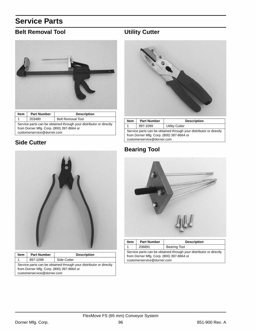
Service Parts
Belt Removal ToolSide Cutter
Utility Cutter
Bearing Tool
Item Part Number Description
1 203480 Belt Removal Tool
Service parts can be obtained through your distributor or directly from Dorner Mfg. Corp. (800) 397-8664 or [email protected]
Item Part Number Description
1 897-1098 Side Cutter
Service parts can be obtained through your distributor or directly from Dorner Mfg. Corp. (800) 397-8664 or [email protected]
Item Part Number Description
1 897-1099 Utility Cutter
Service parts can be obtained through your distributor or directly from Dorner Mfg. Corp. (800) 397-8664 or [email protected]
Item Part Number Description
1 206891 Bearing Tool
Service parts can be obtained through your distributor or directly from Dorner Mfg. Corp. (800) 397-8664 or [email protected]
Dorner Mfg. Corp. 96 851-900 Rev. A
FlexMove FS (65 mm) Conveyor System
Notes
851-900 Rev. A 97 Dorner Mfg. Corp.
FlexMove FS (65 mm) Conveyor System
Return Policy
Returns must have prior written factory authorization or they will not be accepted. Items that are returned to Dorner without authorization will not be credited nor returned to the original sender. When calling for authorization, please have the following information ready for the Dorner factory representative or your local distributor:1. Name and address of customer.2. Dorner part number(s) of item(s) being returned.3. Reason for return.4. Customer's original order number used when ordering the item(s).5. Dorner or distributor invoice number. Include part serial number if available.A representative will discuss action to be taken on the returned items and provide a Returned Materials Authorization (RMA) number for reference. RMA will automatically close 30 days after being issued. To get credit, items must be new and undamaged. There will be a return charge on all items returned for credit, where Dorner was not at fault. It is the customer’s responsibility to prevent damage during return shipping. Damaged or modified items will not be accepted. The customer is responsible for return freight.
Returns will not be accepted after 60 days from original invoice date. The return charge covers inspection, cleaning, disassembly, disposal and reissuing of components to inventory. If a replacement is needed prior to evaluation of returned item, a purchase order must be issued. Credit (if any) is issued only after return and evaluation is complete.Dorner has representatives throughout the world. Contact Dorner for the name of your local representative. Our Customer Service Team will gladly help with your questions on Dorner products.For a copy of Dorner's Warranty, contact Dorner, an authorized sales channel or visit our website: www.dorner.com.For replacement parts, contact an authorized Dorner Service Center or the factory.
Product Type
Standard Products Engineered to order parts
Product Line Conveyors Gearmotors & Mounting Packages
Support Stands
Accessories Spare Parts (non-belt)
Spare Belts - Standard Flat Fabric
Spare Belts - Cleated &
Spec. Fabric
Spare Belts - Plastic Chain
All equipment and parts
1100 Series
30% return fee for all products except:50% return fee for conveyors with modular belt,
cleated belt or speciality belts
All Electrical items are assigned original manufacturers return policy.non-returnable case-by-case
2200 Series
3200 Series
Pallet Systems
FlexMove/SmartFlex
GAL Series
All Electrical
7100 Series
50% return fee for all products7200/7300 Series
AquaGard 7350 Series Version 2
GES Series
AquaGard7350/7360 Series non-returnableAquaPruf Series
851-900 Rev. A Printed in U.S.A.