Embed Size (px)
Citation preview
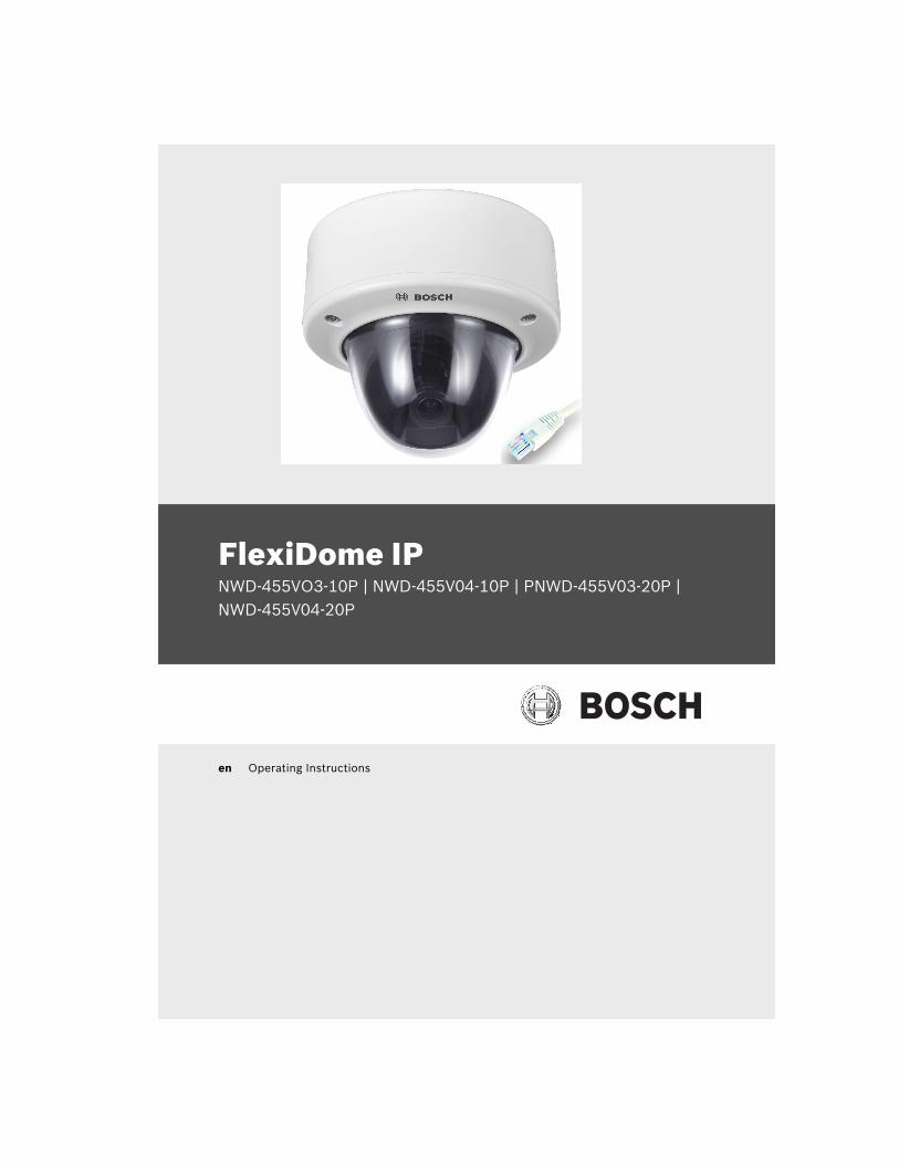
FlexiDome IPNWD-455VO3-10P | NWD-455V04-10P | PNWD-455V03-20P | NWD-455V04-20P
en Operating Instructions

FlexiDome IP | en 3
Bosch Security Systems Operating Instructions V 1.0 | 2006.12
Table of Contents
1 Introduction 151.1 Type number overview 161.2 Unpacking 161.3 System requirements 171.4 Overview of functions 171.4.1 Wide dynamic range 181.4.2 Power-over-Ethernet 181.4.3 Receiver 181.4.4 Video encoding 181.4.5 Tri Streaming 181.4.6 Recording 181.4.7 Multicast 191.4.8 Encryption 191.4.9 Configuration 191.4.10 Tampering recognition and motion detectors 191.4.11 Snapshots 191.4.12 Backup 191.4.13 Intelligent Video Motion Detection 20
2 Disassembly 21
3 Mounting the unit 223.1 Attach the mounting plate 233.2 Make the connections 233.2.1 Power connection 243.2.2 Network (and PoE) connection 243.3 Mount the camera 24
4 Camera set-up 254.1 Camera positioning 254.2 Focal length and focus 264.3 Basic settings 264.3.1 Install menu 27
4 en | FlexiDome IP
V 1.0 | 2006.12 Operating Instructions Bosch Security Systems
4.3.2 Defaults 284.4 Closing the unit 28
5 Network connection 295.1 System requirements 295.2 Establishing the connection 295.3 Secured network 31
6 Operation via the browser 326.1 Livepage 326.1.1 Processor load 326.1.2 Image selection 336.1.3 System log / Event log 336.1.4 Saving snapshots 336.1.5 Recording video sequences 336.1.6 Running recording program 346.2 Recordings page 356.2.1 Selecting recordings 356.2.2 Controlling playback 36
7 Configuration via the browser 397.1 Settings 397.2 General Settings 417.2.1 Camera identification 417.2.2 Password protection 417.2.3 Language selection 437.2.4 Date and time 437.2.5 Time server 437.3 Display Settings 457.3.1 Display stamping 457.4 Encoder Settings 467.4.1 Selecting an encoder profile 467.4.2 Changing profiles 487.4.3 JPEG posting 517.5 Camera settings 527.5.1 ALC 53
FlexiDome IP | en 5
Bosch Security Systems Operating Instructions V 1.0 | 2006.12
7.5.2 Enhance 547.5.3 Color 557.5.4 Installer options 567.6 Recording 567.6.1 Type 577.6.2 Storage information 577.7 iSCSI settings 587.7.1 iSCSI IP address 587.7.2 iSCSI LUN map 597.7.3 Target IP address 597.7.4 Target node 597.7.5 Target LUN 597.7.6 Target password 597.7.7 Initiator name 607.7.8 Initiator extension 607.7.9 Decoupling the drive used 607.7.10 Storage information 607.8 Partitioning 617.8.1 Creating a partition 617.8.2 Partition status 637.8.3 Editing a partition 637.8.4 Deleting partitions 667.9 Recording profile 667.10 Recording scheduler 697.10.1 Activating recording 707.10.2 Recording status 717.11 Alarm Settings 717.11.1 Alarm connections 717.12 VCA 747.12.1 Analysis 747.12.2 Analysis type 757.12.3 Motion detector 757.12.4 Sensitivity 757.12.5 Tamper detection 777.13 Alarm e-mail 797.13.1 Send alarm e-mail 797.13.2 Mail server IP address 79
6 en | FlexiDome IP
V 1.0 | 2006.12 Operating Instructions Bosch Security Systems
7.13.3 Layout 797.13.4 Destination address 807.13.5 Sender name 807.13.6 Send e-mail for testing 807.14 Service Settings 817.14.1 Network 817.14.2 Multicasting 847.14.3 Encryption 867.14.4 Version information 877.14.5 Livepage configuration 887.14.6 Licenses 907.14.7 Maintenance 917.15 Function test 93
8 Connections between video servers 948.0.1 Installation 948.0.2 Establishing the connection 948.0.3 Connect on alarm 948.0.4 Connecting with a Web browser 958.0.5 Closing the connection 95
9 Operation with decoder software 96
10 Maintenance 9710.1 Testing the network connection 9710.2 Repairs 9710.2.1 Transfer and disposal 97
11 Troubleshooting 98
12 Specifications 10012.1 Dimensions (mm/inch) 10212.2 Accessories 10212.2.1 Power transformers 102
FlexiDome IP | en 7
Bosch Security Systems Operating Instructions V 1.0 | 2006.12
13 Glossary 103
8 en | FlexiDome IP
V 1.0 | 2006.12 Operating Instructions Bosch Security Systems
Important safety instructionsRead, follow, and retain all of the following safety instructions. Heed all warnings on the unit and in the operating instructions before operating the unit.1. Cleaning - Unplug the unit from the outlet before cleaning.
Follow any instructions provided with the unit. Generally, using a dry cloth for cleaning is sufficient, but a moist fluff-free cloth or leather shammy may also be used. Do not use liquid cleaners or aerosol cleaners.
2. Heat Sources - Do not install the unit near any heat sources such as radiators, heaters, stoves, or other equipment (including amplifiers) that produce heat.
3. Water - Do not use this unit near water, for example near a bathtub, washbowl, sink, laundry basket, in a damp or wet basement, near a swimming pool, in an unprotected out-door installation, or in any area classified as a wet location. To reduce the risk of fire or electrical shock, do not expose this unit to rain or moisture.
4. Object and liquid entry - Never push objects of any kind into this unit through openings as they may touch danger-ous voltage points or short-out parts that could result in a fire or electrical shock. Never spill liquid of any kind on the unit. Do not place objects filled with liquids, such as vases or cups, on the unit.
5. Controls adjustment - Adjust only those controls specified in the operating instructions. Improper adjustment of other controls may cause damage to the unit. Use of con-trols or adjustments, or performance of procedures other than those specified, may result in hazardous radiation exposure.
6. Overloading - Do not overload outlets and extension cords. This can cause fire or electrical shock.
7. Power cord and plug protection - Protect the plug and power cord from foot traffic, being pinched by items placed upon or against them at electrical outlets, and its exit from the unit. For units intended to operate with
FlexiDome IP | en 9
Bosch Security Systems Operating Instructions V 1.0 | 2006.12
230 VAC, 50 Hz, the input and output power cord must comply with the latest versions of IEC Publication 227 or IEC Publication 245. For outdoor use the power cord must comply to NEC400-4 (CEC Rule 4-010) and marked with OUTDOOR, W, or W-A.
8. Power sources - Operate the unit only from the type of power source indicated on the label. Before proceeding, be sure to disconnect the power from the cable to be installed into the unit.– For battery powered units, refer to the operating
instructions.– For external power supplied units, use only the rec-
ommended or approved power supplies.– For limited power source units, this power source
must comply with EN60950. Substitutions may dam-age the unit or cause fire or shock.
– For 24 VAC units, voltage applied to the unit's power input should not exceed 28 VAC. User-supplied wiring must comply with local electrical codes (Class 2 power levels). Do not ground the supply at the termi-nals or at the unit's power supply terminals.
– If unsure of the type of power supply to use, contact your dealer or local power company.
9. Servicing - Do not attempt to service this unit yourself. Opening or removing covers may expose you to dangerous voltage or other hazards. Refer all servicing to qualified service personnel.
10. Damage requiring service - Unplug the unit from the main AC power source and refer servicing to qualified service personnel when any damage to the equipment has occurred, such as:– the power supply cord or plug is damaged;– exposure to moisture, water, and/or inclement
weather (rain, snow, etc.);– liquid has been spilled in or on the equipment;– an object has fallen into the unit;– unit has been dropped or the unit cabinet is damaged;
10 en | FlexiDome IP
V 1.0 | 2006.12 Operating Instructions Bosch Security Systems
– unit exhibits a distinct change in performance;– unit does not operate normally when the user cor-
rectly follows the operating instructions.11. Replacement parts - Be sure the service technician uses
replacement parts specified by the manufacturer, or that have the same characteristics as the original parts. Unau-thorized substitutions may cause fire, electrical shock, or other hazards.
12. Safety check - Safety checks should be performed upon completion of service or repairs to the unit to ensure proper operating condition.
13. Installation - Install in accordance with the manufacturer's instructions and in accordance with applicable local codes.
14. Attachments, changes, or modifications - Only use attach-ments/accessories specified by the manufacturer. Any change or modification of the equipment, not expressly approved by Bosch, could void the warranty or, in the case of an authorization agreement, authority to operate the equipment.
FlexiDome IP | en 11
Bosch Security Systems Operating Instructions V 1.0 | 2006.12
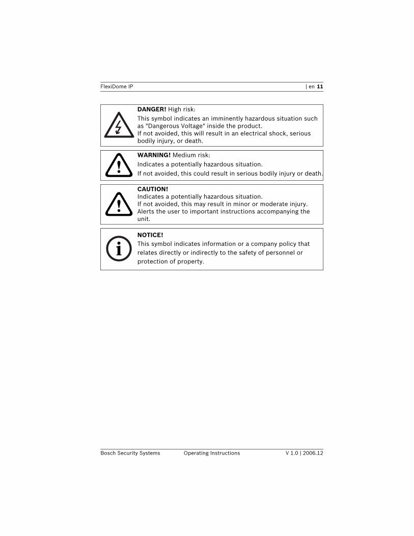
DANGER! High risk:This symbol indicates an imminently hazardous situation such as "Dangerous Voltage" inside the product.If not avoided, this will result in an electrical shock, serious bodily injury, or death.
!WARNING! Medium risk:Indicates a potentially hazardous situation.If not avoided, this could result in serious bodily injury or death.
!CAUTION! Indicates a potentially hazardous situation.If not avoided, this may result in minor or moderate injury.Alerts the user to important instructions accompanying the unit.
iNOTICE! This symbol indicates information or a company policy that relates directly or indirectly to the safety of personnel or protection of property.
12 en | FlexiDome IP
V 1.0 | 2006.12 Operating Instructions Bosch Security Systems
Video lossVideo loss is inherent to digital video recording; therefore, Bosch Security Systems cannot be held liable for any damage that results from missing video information. To minimize the risk of lost digital information, Bosch Security Systems recom-mends multiple, redundant recording systems, and a procedure to back up all analog and digital information.
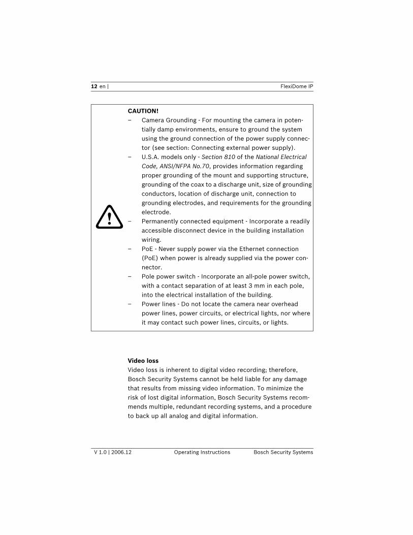
!
CAUTION! – Camera Grounding - For mounting the camera in poten-
tially damp environments, ensure to ground the system using the ground connection of the power supply connec-tor (see section: Connecting external power supply).
– U.S.A. models only - Section 810 of the National Electrical Code, ANSI/NFPA No.70, provides information regarding proper grounding of the mount and supporting structure, grounding of the coax to a discharge unit, size of grounding conductors, location of discharge unit, connection to grounding electrodes, and requirements for the grounding electrode.
– Permanently connected equipment - Incorporate a readily accessible disconnect device in the building installation wiring.
– PoE - Never supply power via the Ethernet connection (PoE) when power is already supplied via the power con-nector.
– Pole power switch - Incorporate an all-pole power switch, with a contact separation of at least 3 mm in each pole, into the electrical installation of the building.
– Power lines - Do not locate the camera near overhead power lines, power circuits, or electrical lights, nor where it may contact such power lines, circuits, or lights.
FlexiDome IP | en 13
Bosch Security Systems Operating Instructions V 1.0 | 2006.12
FCC & ICES Information(U.S.A. and Canadian Models Only)This equipment has been tested and found to comply with the limits for a Class B digital device, pursuant to part 15 of the FCC Rules. These limits are designed to provide reasonable pro-tection against harmful interference in a residential installation. This equipment generates, uses, and can radiate radio fre-quency energy and, if not installed and used in accordance with the instructions, may cause harmful interference to radio com-munications. However, there is no guarantee that interference will not occur in a particular installation. If this equipment does cause harmful interference to radio or television reception, which can be determined by turning the equipment off and on, the user is encouraged to try to correct the interference by one or more of the following measures:
– reorient or relocate the receiving antenna;– increase the separation between the equipment and
receiver;– connect the equipment into an outlet on a circuit dif-
ferent from that to which the receiver is connected;– consult the dealer or an experienced radio/TV techni-
cian for help.
DisclaimerUnderwriter Laboratories Inc. ("UL") has not tested the perfor-mance or reliability of the security or signaling aspects of this product. UL has only tested fire, shock and/or casualty hazards as outlined in UL's Standard(s) for Safety for Information Tech-nology Equipment, UL 60950-1. UL Certification does not cover the performance or reliability of the security or signaling aspects of this product.UL MAKES NO REPRESENTATIONS, WARRANTIES, OR CERTIFI-CATIONS WHATSOEVER REGARDING THE PERFORMANCE OR RELIABILITY OF ANY SECURITY OR SIGNALING RELATED FUNC-TIONS OF THIS PRODUCT.
14 en | FlexiDome IP
V 1.0 | 2006.12 Operating Instructions Bosch Security Systems
Environmental statement - Bosch has a strong commitment towards the environment. This unit has been designed to respect the environment as much as possible.For additional information, please contact the Bosch Security Systems location nearest you or visit our web site at www.boschsecuritysystems.com
Disposal
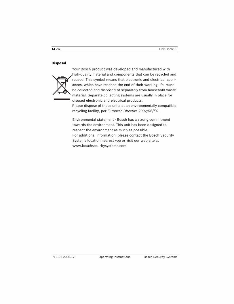
Your Bosch product was developed and manufactured with high-quality material and components that can be recycled and reused. This symbol means that electronic and electrical appli-ances, which have reached the end of their working life, must be collected and disposed of separately from household waste material. Separate collecting systems are usually in place for disused electronic and electrical products. Please dispose of these units at an environmentally compatible recycling facility, per European Directive 2002/96/EC.
FlexiDome IP Introduction | en 15
Bosch Security Systems Operating Instructions V 1.0 | 2006.12
1 IntroductionThe FlexiDome IP camera is a small, discreet, high-security sur-veillance dome containing a high-performance 1/3-inch CCD color camera with integral varifocal lens. The integrated unit is mounted to a wall or ceiling. The sturdy construction and high impact resistant polycarbon dome protect the camera module from damage.The smart camera incorporates advanced digital signal process-ing for outstanding picture performance. The integrated camera unit operates as a network video server and transmits video and control signals over data networks such as Ethernet LANs and the Internet.The FlexiDome IP camera is easy to install and ready to use, and offers the best solution for demanding scene conditions. Fea-tures include:– Impact-resistant dome– Tamper-resistant housing– Intelligent Video Motion Detection (iso enhanced)– Video and data transmission over IP data networks– Tri Streaming function for simultaneous encoding with
three individually definable profiles– Multicast function for simultaneous picture transmission to
multiple receivers– Video encoding using international MPEG-4 standard– Integrated Ethernet interface (10/100 Base-T)– Configuration and remote control of all built-in functions
via TCP/IP and secure HTTPS– Password protection to prevent unauthorized connection
or configuration changes– Event-driven, automatic connection– Convenient maintenance via uploads– Flexible control and data channel encryption– Authentication according to the 802.1x standard
– NightSenseTM extends the camera’s low-light performance.
16 en | Introduction FlexiDome IP
V 1.0 | 2006.12 Operating Instructions Bosch Security Systems
1.1 Type number overview
Table 1.1 FlexiDome IP type numbers
1.2 UnpackingUnpack carefully and handle the equipment with care. The packaging contains:– Integrated FlexiDome IP camera unit– Mounting hardware kit – Special screwdriver bit for tamper-resistant screws– Lens adjustment cap– CD ROM
– Manual– System requirements– Configuration Manager– MPEG ActiveX control– DirextX control– Microsoft Internet Explorer– Sun JVM– Player and archive player– Adobe Acrobat Reader
Type number NWD-455V03-10P NWD-455V04-10P NWD-455V03-20P NWD-495V04-20P
Lens Varifocal
2.6 to 6 mm
F1.4
Varifocal
3.7 to 12 mm
F1.6
Varifocal
2.6 to 6 mm
F1.4
Varifocal
3.7 to 12 mm
F1.6
Standard PAL NTSC
Supply volt-
age
24 VAC, 50 Hz or +12 VDC
(use class 2 power supply) or
PoE (IEEE 802.3af)
24 VAC, 60 Hz or +12 VDC
(use class 2 power supply) or
PoE (IEEE 802.3af)
iNOTICE! If equipment appears to have been damaged during shipment, repack it in the original packaging and notify the shipping agent or supplier.
FlexiDome IP Introduction | en 17
Bosch Security Systems Operating Instructions V 1.0 | 2006.12
1.3 System requirements– Computer with Windows 2000/XP operating system, net-
work access and Microsoft Internet Explorer web browser version 6.0 or later or
– Computer with Windows 2000/XP operating system, net-work access and reception software, for example VIDOS, BMVS or DIBOS 8.0or
– MPEG-4 compatible hardware decoder from Bosch Security Systems (such as VIP XD) as a receiver and a connected video monitor
The minimum PC requirements are:– Operating platform: a PC running Windows 2000 or Win-
dows XP with IE6.0– Processor:1.8 GHz Pentium IV– RAM memory: 256 MB– Video system: 128 MB video memory, 1024x768 display
with 24-bit color– Network interface: 100-BaseT – DirectX: 9.0b
1.4 Overview of functionsThe integrated camera unit incorporates a network video server. Its primary function is to encode video and control data for transmission over an IP network. With its MPEG-4 encoding it is bandwidth efficient for both network and recording. The use of existing networks means that integration with CCTV sys-tems or local networks can be achieved quickly and easily.
iNOTICE! Make sure the graphics card is set to 16-bit or 32-bit color depth and that Sun JVM is installed on your PC. To play back live video images, an appropriate MPEG ActiveX must be installed on the computer. If necessary, install the required software and controls from the product CD provided. If you need further assistance, contact your PC system administrator.
18 en | Introduction FlexiDome IP
V 1.0 | 2006.12 Operating Instructions Bosch Security Systems
Video images from a single camera can be simultaneously received on several receivers.
1.4.1 Wide dynamic rangeThe digital signal is automatically processed to optimally cap-ture the detail in both the high and low light areas of the scene simultaneously, maximizing the information visible in the pic-ture.
1.4.2 Power-over-EthernetPower for the camera can be supplied via a Power-over-Ether-net (IEEE 802.3af) compliant network cable connection. With this configuration, only a single cable connection is required to view, power and control the camera.
1.4.3 ReceiverMPEG-4 compatible hardware decoders (for example VIP XD) can be used as a receiver. Computers with decoding software such as VIDOS or computers with the Microsoft Internet Explorer web browser installed can also be used as receivers.
1.4.4 Video encodingThe camera uses the MPEG-4 compression standard. Thanks to efficient encoding, the data rate remains low even with high image quality and can also be adapted to local conditions within wide limits.
1.4.5 Tri StreamingTri Streaming allows the incoming data stream to be encoded simultaneously according to three different, individually cus-tomized profiles. This creates two MPEG4 streams per camera that can serve different purposes, for example, one for local recording and one optimized for transmission over the LAN, and an additional JPEG stream for use with a PDA.
1.4.6 RecordingThe camera can be used with an iSCSI server connected via the network to store long-term recordings.
FlexiDome IP Introduction | en 19
Bosch Security Systems Operating Instructions V 1.0 | 2006.12
1.4.7 MulticastIn suitably configured networks, the multicast function enables simultaneous, real time transmission to multiple receivers. The prerequisite for this is that the UDP and IGMP V2 protocols are implemented on the network.
1.4.8 Encryption The data transmissions and the authentication channel can be encrypted to prevent unauthorized access. Web browser con-nections can be protected using HTTPS.
1.4.9 ConfigurationThe camera can be configured using a browser on the local net-work (Intranet) or from the Internet. Similarly, firmware updates and rapid loading of device configurations are also pos-sible. Configuration settings can be stored as files on a com-puter and copied from one camera to another.
1.4.10 Tampering recognition and motion detectorsThe camera offers a wide range of configuration options for alarm signaling in the event of tampering with the camera. An algorithm for detecting movement in the video image is also part of the scope of delivery and can optionally be extended to include special video analysis algorithms.
1.4.11 SnapshotsIndividual video frames (snapshots) can be called up as JPEG images, stored on the hard drive or displayed in a separate browser window.
1.4.12 BackupThe browser application Livepage has an icon for saving the video images provided by the unit as a file on your computer's hard drive. Clicking this icon stores the video sequences and they can be replayed with the Player from Bosch Security Systems included with the package.
20 en | Introduction FlexiDome IP
V 1.0 | 2006.12 Operating Instructions Bosch Security Systems
1.4.13 Intelligent Video Motion DetectionThe intelligent video motion detection (iVMD) system of the camera uses advanced analysis algorithms with comprehensive functions for the detection of motion.
FlexiDome IP Disassembly | en 21
Bosch Security Systems Operating Instructions V 1.0 | 2006.12
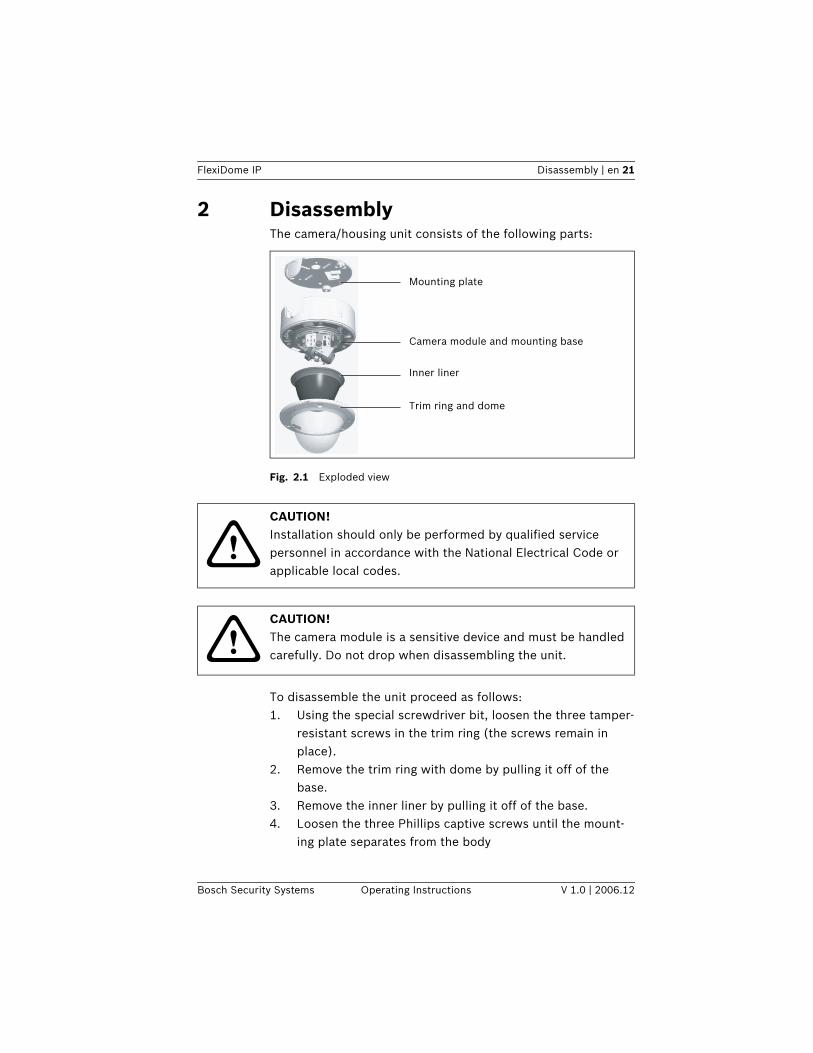
2 DisassemblyThe camera/housing unit consists of the following parts:
Fig. 2.1 Exploded view
To disassemble the unit proceed as follows:1. Using the special screwdriver bit, loosen the three tamper-
resistant screws in the trim ring (the screws remain in place).
2. Remove the trim ring with dome by pulling it off of the base.
3. Remove the inner liner by pulling it off of the base.4. Loosen the three Phillips captive screws until the mount-
ing plate separates from the body
Mounting plate
Camera module and mounting base
Inner liner
Trim ring and dome
!CAUTION! Installation should only be performed by qualified service personnel in accordance with the National Electrical Code or applicable local codes.
!CAUTION! The camera module is a sensitive device and must be handled carefully. Do not drop when disassembling the unit.
22 en | Mounting the unit FlexiDome IP
V 1.0 | 2006.12 Operating Instructions Bosch Security Systems
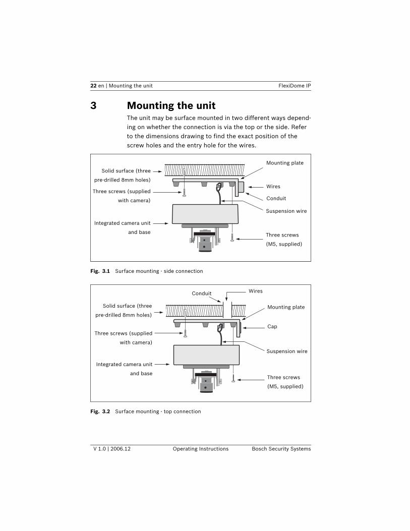
3 Mounting the unitThe unit may be surface mounted in two different ways depend-ing on whether the connection is via the top or the side. Refer to the dimensions drawing to find the exact position of the screw holes and the entry hole for the wires.
Fig. 3.1 Surface mounting - side connection
Fig. 3.2 Surface mounting - top connection
Wires
Mounting plate
Conduit
Integrated camera unit
and base Three screws
(M5, supplied)
Three screws (supplied
with camera)
Solid surface (three
pre-drilled 8mm holes)
Suspension wire
Cap
Mounting plate
Conduit
Three screws (supplied
with camera)
Integrated camera unit
and base
Solid surface (three
pre-drilled 8mm holes)
Three screws
(M5, supplied)
Wires
Suspension wire
FlexiDome IP Mounting the unit | en 23
Bosch Security Systems Operating Instructions V 1.0 | 2006.12
3.1 Attach the mounting plate1. Use the mounting plate as a drilling template to drill three
holes in the mounting surface.2. Use the supplied plugs and screws to attach the mounting
plate to the surface.3. With a rear connection, leave the cap in place. With a side
connection:a. remove the cap covering the side entrance;b. attach a 22 mm / ½ inch (PG16) gland conduit to the
mounting plate.
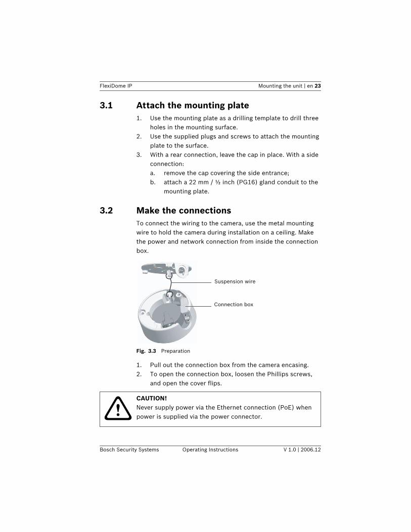
3.2 Make the connectionsTo connect the wiring to the camera, use the metal mounting wire to hold the camera during installation on a ceiling. Make the power and network connection from inside the connection box.
Fig. 3.3 Preparation
1. Pull out the connection box from the camera encasing.2. To open the connection box, loosen the Phillips screws,
and open the cover flips.
Suspension wire
Connection box
!CAUTION! Never supply power via the Ethernet connection (PoE) when power is supplied via the power connector.
24 en | Mounting the unit FlexiDome IP
V 1.0 | 2006.12 Operating Instructions Bosch Security Systems
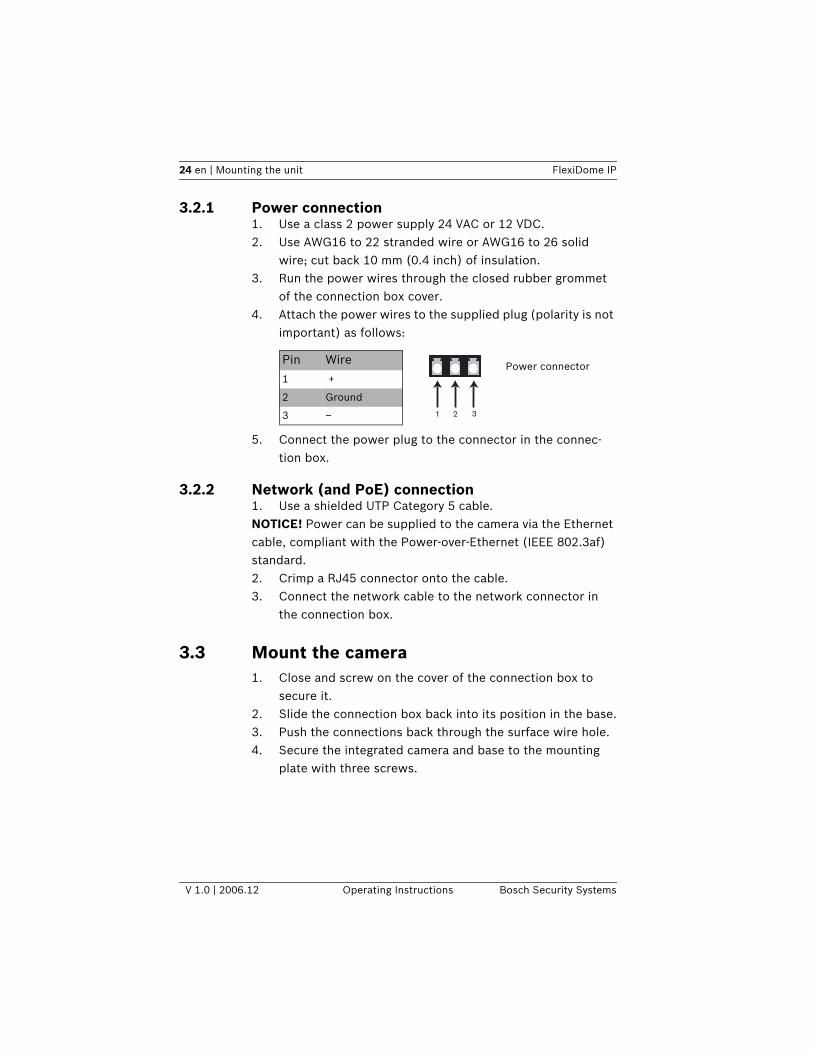
3.2.1 Power connection1. Use a class 2 power supply 24 VAC or 12 VDC.2. Use AWG16 to 22 stranded wire or AWG16 to 26 solid
wire; cut back 10 mm (0.4 inch) of insulation.3. Run the power wires through the closed rubber grommet
of the connection box cover.4. Attach the power wires to the supplied plug (polarity is not
important) as follows:
5. Connect the power plug to the connector in the connec-tion box.
3.2.2 Network (and PoE) connection1. Use a shielded UTP Category 5 cable. NOTICE! Power can be supplied to the camera via the Ethernet cable, compliant with the Power-over-Ethernet (IEEE 802.3af) standard.2. Crimp a RJ45 connector onto the cable.3. Connect the network cable to the network connector in
the connection box.
3.3 Mount the camera1. Close and screw on the cover of the connection box to
secure it.2. Slide the connection box back into its position in the base.3. Push the connections back through the surface wire hole.4. Secure the integrated camera and base to the mounting
plate with three screws.
1 32
Pin Wire
1 +
2 Ground
3 –
Power connector
FlexiDome IP Camera set-up | en 25
Bosch Security Systems Operating Instructions V 1.0 | 2006.12
4 Camera set-up
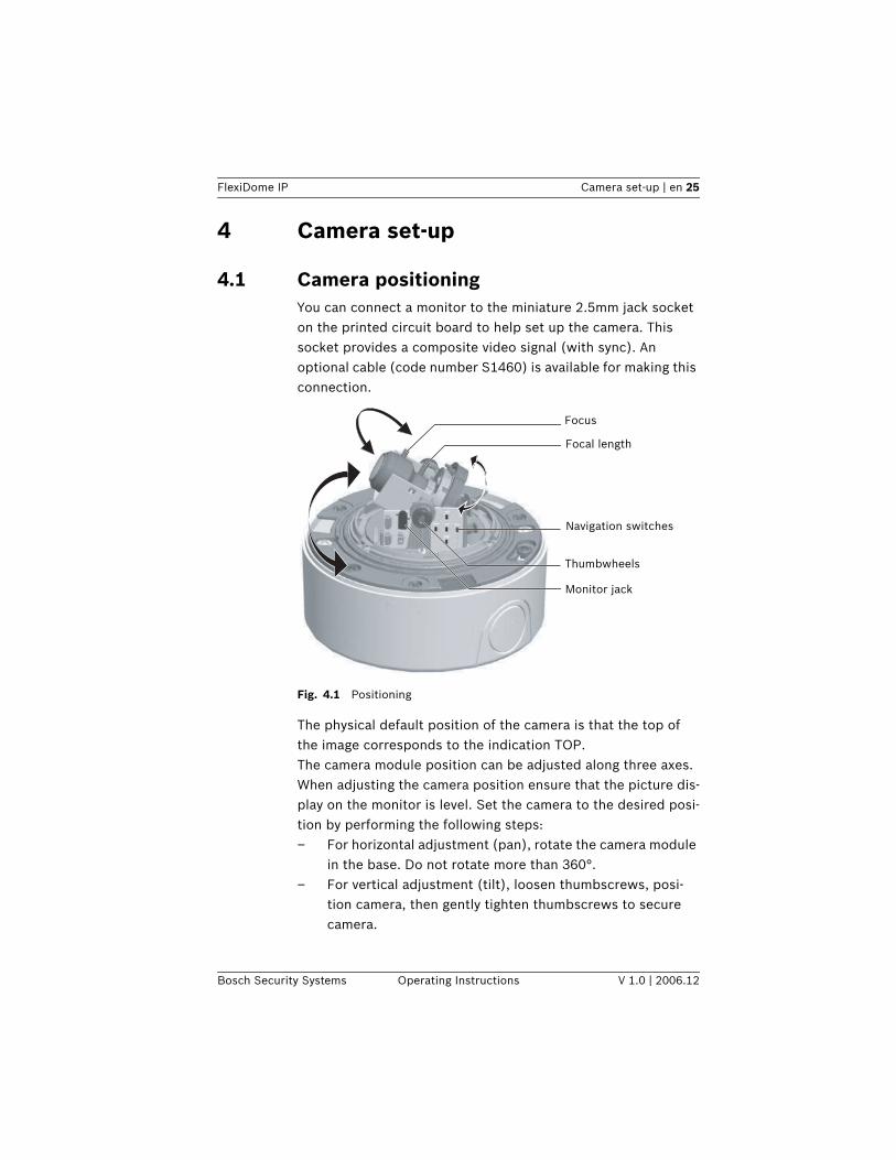
4.1 Camera positioningYou can connect a monitor to the miniature 2.5mm jack socket on the printed circuit board to help set up the camera. This socket provides a composite video signal (with sync). An optional cable (code number S1460) is available for making this connection.
Fig. 4.1 Positioning
The physical default position of the camera is that the top of the image corresponds to the indication TOP. The camera module position can be adjusted along three axes. When adjusting the camera position ensure that the picture dis-play on the monitor is level. Set the camera to the desired posi-tion by performing the following steps:– For horizontal adjustment (pan), rotate the camera module
in the base. Do not rotate more than 360°.– For vertical adjustment (tilt), loosen thumbscrews, posi-
tion camera, then gently tighten thumbscrews to secure camera.
Navigation switches
Thumbwheels
Monitor jack
Focal length
Focus
26 en | Camera set-up FlexiDome IP
V 1.0 | 2006.12 Operating Instructions Bosch Security Systems
– To obtain a horizontal horizon (for tilted ceilings or side-wall mounting), rotate the base of the lens as necessary to align the picture shown on the monitor. Do not rotate more than 340°.
4.2 Focal length and focusBefore adjusting, place the adjustment cap on the lens to ensure that the image sharpness is the same as when the dome is in place.1. To set the field of view of the varifocal lens, loosen the
focal length screw and turn the mechanism until the required view is displayed on the monitor. (Image goes out of focus.)
2. Focus the image on the monitor by loosening the focus screw and turning the mechanism until the image is in focus.
3. Readjust the focal length if necessary.4. Repeat these two adjustments until the desired view is in
focus.5. Tighten both screws.6. Remove the adjustment cap from the lens.
4.3 Basic settingsThe camera normally provides an optimal picture without the need for further adjustments. The camera has an Installer menu in which basic installation settings (IP address) can be accessed. Five keys, located on the side panel, are used for nav-igating through the basic set-up menu.
!CAUTION! The CCD image sensors are highly sensitive and require special care for proper performance and extended lifetime. Do not expose them to direct sunlight or bright spotlights in operating and non-operating conditions. Avoid bright lights in the field of view of the camera.
FlexiDome IP Camera set-up | en 27
Bosch Security Systems Operating Instructions V 1.0 | 2006.12
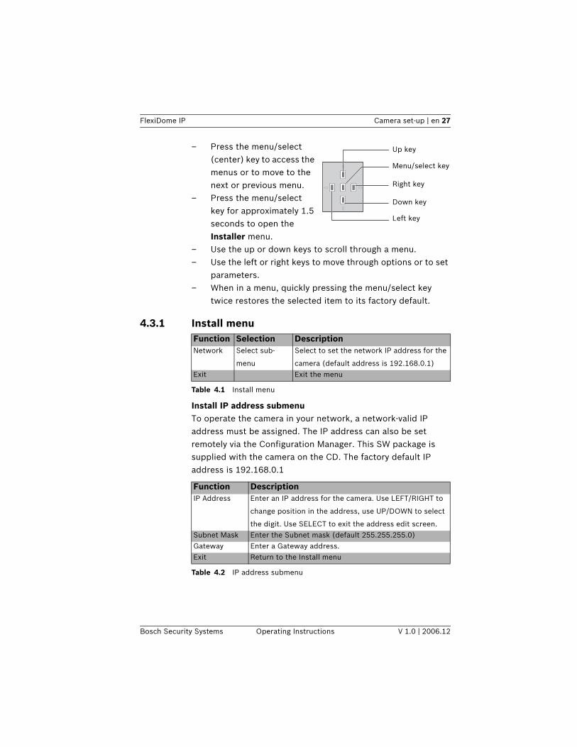
– Press the menu/select (center) key to access the menus or to move to the next or previous menu.
– Press the menu/select key for approximately 1.5 seconds to open the Installer menu.
– Use the up or down keys to scroll through a menu.– Use the left or right keys to move through options or to set
parameters. – When in a menu, quickly pressing the menu/select key
twice restores the selected item to its factory default.
4.3.1 Install menu
Table 4.1 Install menu
Install IP address submenuTo operate the camera in your network, a network-valid IP address must be assigned. The IP address can also be set remotely via the Configuration Manager. This SW package is supplied with the camera on the CD. The factory default IP address is 192.168.0.1
Table 4.2 IP address submenu
Up key
Menu/select key
Right key
Down key
Left key
Function Selection DescriptionNetwork Select sub-
menu
Select to set the network IP address for the
camera (default address is 192.168.0.1)Exit Exit the menu
Function DescriptionIP Address Enter an IP address for the camera. Use LEFT/RIGHT to
change position in the address, use UP/DOWN to select
the digit. Use SELECT to exit the address edit screen.Subnet Mask Enter the Subnet mask (default 255.255.255.0) Gateway Enter a Gateway address. Exit Return to the Install menu
28 en | Camera set-up FlexiDome IP
V 1.0 | 2006.12 Operating Instructions Bosch Security Systems
4.3.2 DefaultsTo restore all parameters (including IP address) to the factory defaults, press and hold the Up navigation key for at least 10 seconds and then confirm. Allow a few seconds for the camera to optimize the picture after a mode reset.
4.4 Closing the unitWhen the camera position is set and all adjustments have been made, close the unit.1. Remove the monitoring jack.2. Place the inner liner in position aligning its fin with the
bracket on the base.3. Place the dome onto the base and rotate until it clips into
place. (If necessary clean its surface with a soft cloth.)4. Place the sealing ring and the trim ring over the dome.5. Align the tamper-resistant screws in the trim ring with the
threaded ends in the mounting base.6. Use the supplied special screwdriver bit to tighten the
three tamper-resistant screws.
iNOTICE! The new IP address, subnet mask and gateway address are set after you leave the menu. The camera reboots internally and the new values are set after a few seconds.
iNOTICE! Restoring the factory defaults may result in the loss of the IP connection. If this occurs, change the IP address of your browser to the factory default value. Only restore the factory defaults when it is absolutely necessary.
FlexiDome IP Network connection | en 29
Bosch Security Systems Operating Instructions V 1.0 | 2006.12
5 Network connectionA computer with Microsoft Internet Explorer can be used to receive live images from the camera, control cameras and replay sequences stored on the local hard drive. The camera is configured over the network using the browser or via the Con-figuration Manager (supplied with the product). The configura-tion options using the menu system of the camera itself are limited to setting up the lens and network.
5.1 System requirements (see page 17 for more detailed requirements)– Microsoft Internet Explorer version 6.0 or higher– Monitor resolution 1024 × 768 pixels, 16 or 32 bit color
depth– Intranet or Internet network access To play back live video images, an appropriate MPEG ActiveX must be installed on the computer. If necessary, the required software and controls can be installed from the product CD provided.
a. Insert the CD into the CD-ROM drive of the computer. If the CD does not start automatically, open the root directory of the CD in Windows Explorer and double click MPEGAx.exe.
b. Follow the on-screen instructions.
5.2 Establishing the connectionThe camera must be assigned a valid IP address to operate on your network. The default address pre-set at the factory is 192.168.0.11. Start the Web browser.2. Enter the IP address of the camera as the URL.
iNOTICE! The camera can also be connected to DIBOS 8.0, VIDOS and BVMS video management systems as well as third party video management systems.
30 en | Network connection FlexiDome IP
V 1.0 | 2006.12 Operating Instructions Bosch Security Systems
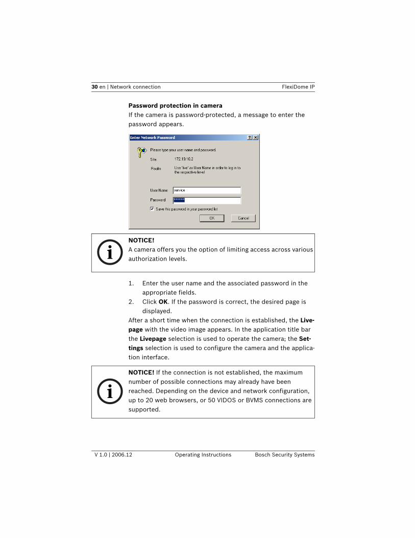
Password protection in cameraIf the camera is password-protected, a message to enter the password appears.
1. Enter the user name and the associated password in the appropriate fields.
2. Click OK. If the password is correct, the desired page is displayed.
After a short time when the connection is established, the Live-page with the video image appears. In the application title bar the Livepage selection is used to operate the camera; the Set-tings selection is used to configure the camera and the applica-tion interface.
iNOTICE! A camera offers you the option of limiting access across various authorization levels.
iNOTICE! If the connection is not established, the maximum number of possible connections may already have been reached. Depending on the device and network configuration, up to 20 web browsers, or 50 VIDOS or BVMS connections are supported.
FlexiDome IP Network connection | en 31
Bosch Security Systems Operating Instructions V 1.0 | 2006.12
5.3 Secured networkIf a Radius server is used for network access control (802.1x authentication), the camera must be configured first. To config-ure the camera for a Radius network, connect it directly to a PC via a crossed network cable and configure the two parameters, identity and password. Only after these have been configured can you communicate with the camera via the network.
32 en | Operation via the browser FlexiDome IP
V 1.0 | 2006.12 Operating Instructions Bosch Security Systems
6 Operation via the browser
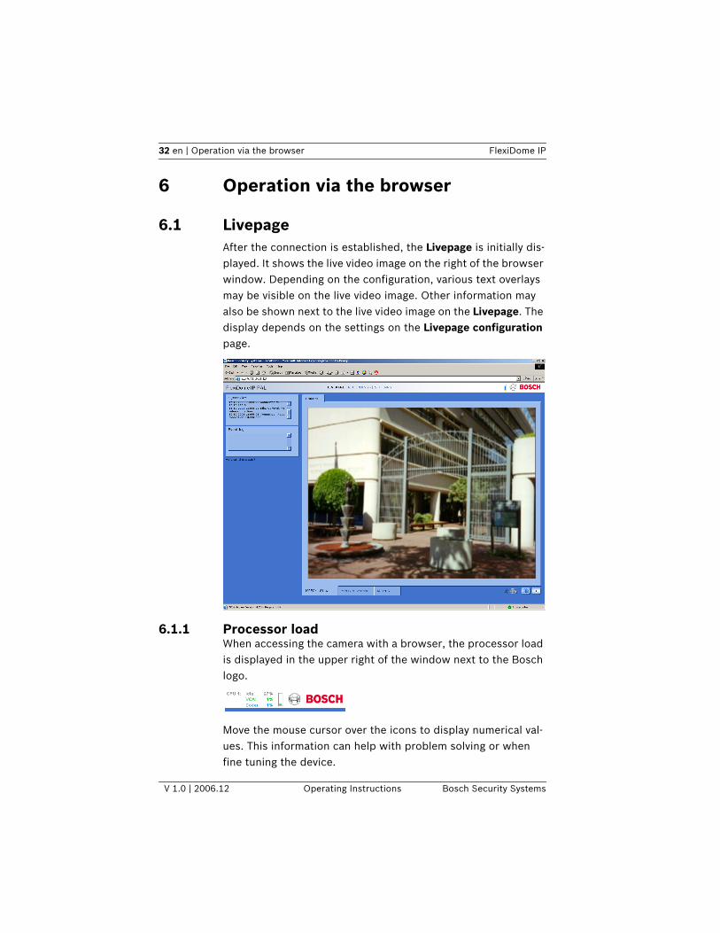
6.1 LivepageAfter the connection is established, the Livepage is initially dis-played. It shows the live video image on the right of the browser window. Depending on the configuration, various text overlays may be visible on the live video image. Other information may also be shown next to the live video image on the Livepage. The display depends on the settings on the Livepage configuration page.
6.1.1 Processor load When accessing the camera with a browser, the processor load is displayed in the upper right of the window next to the Bosch logo.
Move the mouse cursor over the icons to display numerical val-ues. This information can help with problem solving or when fine tuning the device.
FlexiDome IP Operation via the browser | en 33
Bosch Security Systems Operating Instructions V 1.0 | 2006.12
6.1.2 Image selectionYou can view the image on a full screen. – Click on one of the MPEG-4 Stream 1, MPEG-4 Stream 2 or
M-JPEG tabs below the video image to switch between the different displays for the camera image.
6.1.3 System log / Event log
The System log field contains information about the operating status of the camera and the connection. These messages can be saved automatically in a file. Events such as the triggering or end of alarms are shown in the Event log field. These messages can be saved automatically in a file.
6.1.4 Saving snapshotsIndividual images from the video sequence that is currently being shown on the Livepage can be saved in JPEG format on the computer's hard drive.
1. Click the camera icon to save single images.2. The image is saved at a resolution of 704 × 576/480 pixels
(4CIF). The storage location depends on the configuration of the camera.
6.1.5 Recording video sequencesSections of the video sequence that is currently being shown on the Livepage can be saved on the computer's hard drive. The sequences are recorded at the resolution specified in the encoder configuration. The storage location depends on the configuration of the camera.
34 en | Operation via the browser FlexiDome IP
V 1.0 | 2006.12 Operating Instructions Bosch Security Systems
1. Click the recording icon to record video sequences.
– Saving begins immediately. The red dot on the icon flashes to indicate that a recording is in progress.
2. Click the symbol for recording video sequences again. Sav-ing is terminated.
Installing PlayerYou can play back saved video sequences using the Player from Bosch Security Systems, which can be found on the software CD supplied.
1. Insert the CD into the CD-ROM drive of the computer. If the CD does not start automatically, open the CD in the Windows Explorer and double click the index.html file to start the installation.
2. Select a language from the list box at the top.3. Click Tools in the menu.4. Click Archive Player; the installation starts. 5. Follow the instructions in the installation program. The
Archive Player is installed together with the Player. 6. After a successful installation, two new icons for the Player
and the Archive Player appear on the desktop.7. Double click the Player icon to start the Player.
6.1.6 Running recording programThe hard drive icon below the camera images on the Livepage changes during an automatic recording.
The icon lights up and displays a moving graphic to indi-cate a running recording. If no recording is taking place, a gray icon is displayed.
iNOTICE! A corresponding MPEG ActiveX (located on the CD provided with the product) must be installed on the computer in order to play back saved video sequences using the Player.
FlexiDome IP Operation via the browser | en 35
Bosch Security Systems Operating Instructions V 1.0 | 2006.12
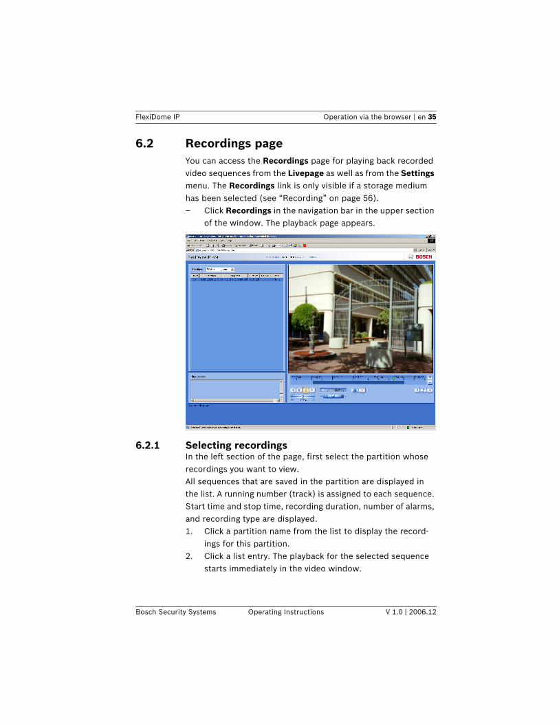
6.2 Recordings pageYou can access the Recordings page for playing back recorded video sequences from the Livepage as well as from the Settings menu. The Recordings link is only visible if a storage medium has been selected (see “Recording” on page 56).– Click Recordings in the navigation bar in the upper section
of the window. The playback page appears..
6.2.1 Selecting recordingsIn the left section of the page, first select the partition whose recordings you want to view.All sequences that are saved in the partition are displayed in the list. A running number (track) is assigned to each sequence. Start time and stop time, recording duration, number of alarms, and recording type are displayed.1. Click a partition name from the list to display the record-
ings for this partition.2. Click a list entry. The playback for the selected sequence
starts immediately in the video window.
36 en | Operation via the browser FlexiDome IP
V 1.0 | 2006.12 Operating Instructions Bosch Security Systems
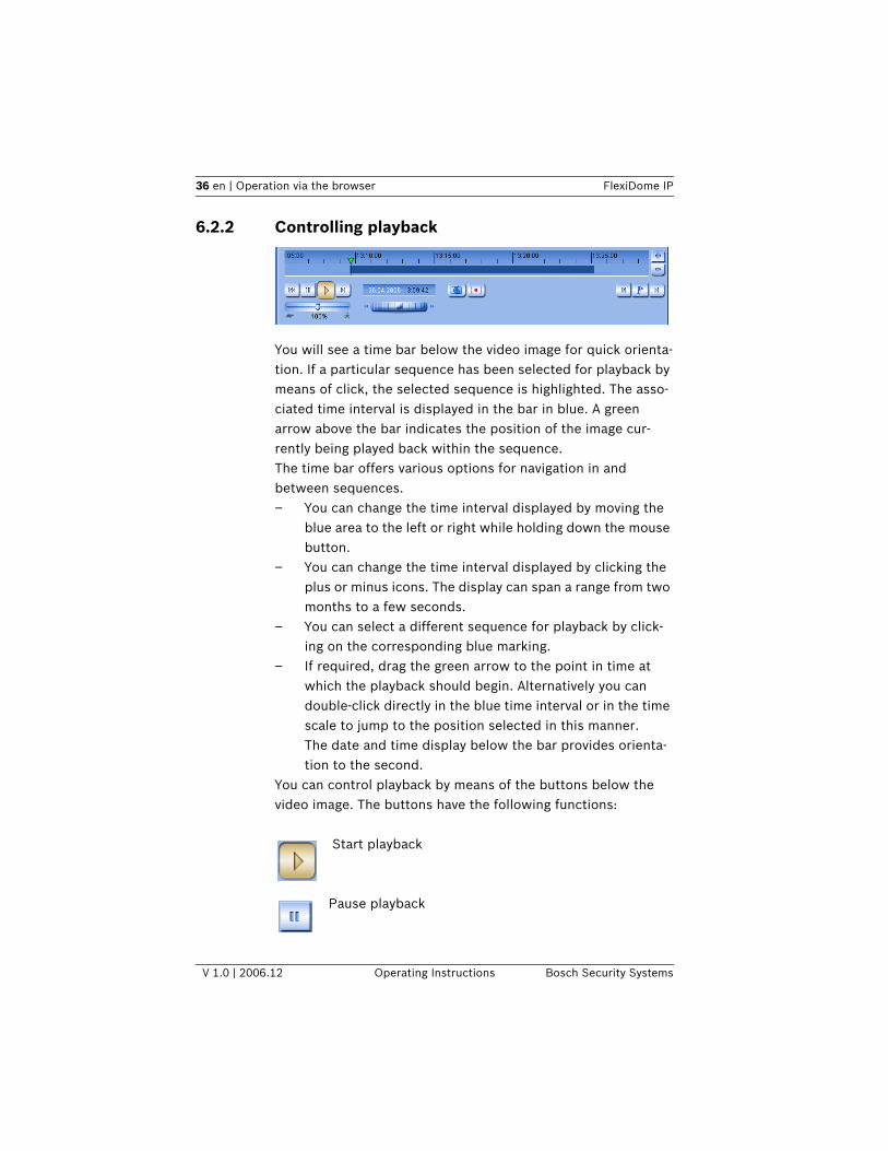
6.2.2 Controlling playback
You will see a time bar below the video image for quick orienta-tion. If a particular sequence has been selected for playback by means of click, the selected sequence is highlighted. The asso-ciated time interval is displayed in the bar in blue. A green arrow above the bar indicates the position of the image cur-rently being played back within the sequence.The time bar offers various options for navigation in and between sequences.– You can change the time interval displayed by moving the
blue area to the left or right while holding down the mouse button.
– You can change the time interval displayed by clicking the plus or minus icons. The display can span a range from two months to a few seconds.
– You can select a different sequence for playback by click-ing on the corresponding blue marking.
– If required, drag the green arrow to the point in time at which the playback should begin. Alternatively you can double-click directly in the blue time interval or in the time scale to jump to the position selected in this manner. The date and time display below the bar provides orienta-tion to the second.
You can control playback by means of the buttons below the video image. The buttons have the following functions:
Start playback
Pause playback
FlexiDome IP Operation via the browser | en 37
Bosch Security Systems Operating Instructions V 1.0 | 2006.12
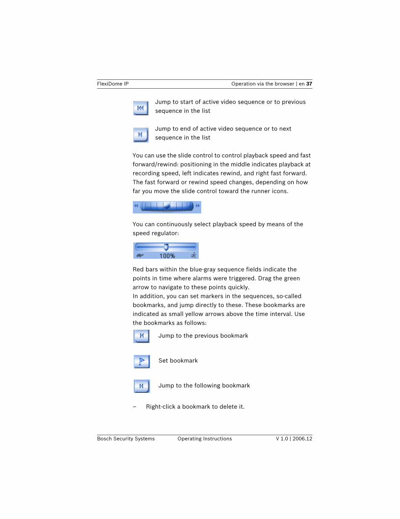
Jump to start of active video sequence or to previous sequence in the list
Jump to end of active video sequence or to next sequence in the list
You can use the slide control to control playback speed and fast forward/rewind: positioning in the middle indicates playback at recording speed, left indicates rewind, and right fast forward. The fast forward or rewind speed changes, depending on how far you move the slide control toward the runner icons.
You can continuously select playback speed by means of the speed regulator:
Red bars within the blue-gray sequence fields indicate the points in time where alarms were triggered. Drag the green arrow to navigate to these points quickly.In addition, you can set markers in the sequences, so-called bookmarks, and jump directly to these. These bookmarks are indicated as small yellow arrows above the time interval. Use the bookmarks as follows:
Jump to the previous bookmark
Set bookmark
Jump to the following bookmark
– Right-click a bookmark to delete it.
38 en | Operation via the browser FlexiDome IP
V 1.0 | 2006.12 Operating Instructions Bosch Security Systems
iNOTICE! Bookmarks are only valid while you are in the Recordings page; they are not saved with the sequences. As soon as you leave the page all bookmarks are deleted.
FlexiDome IP Configuration via the browser | en 39
Bosch Security Systems Operating Instructions V 1.0 | 2006.12
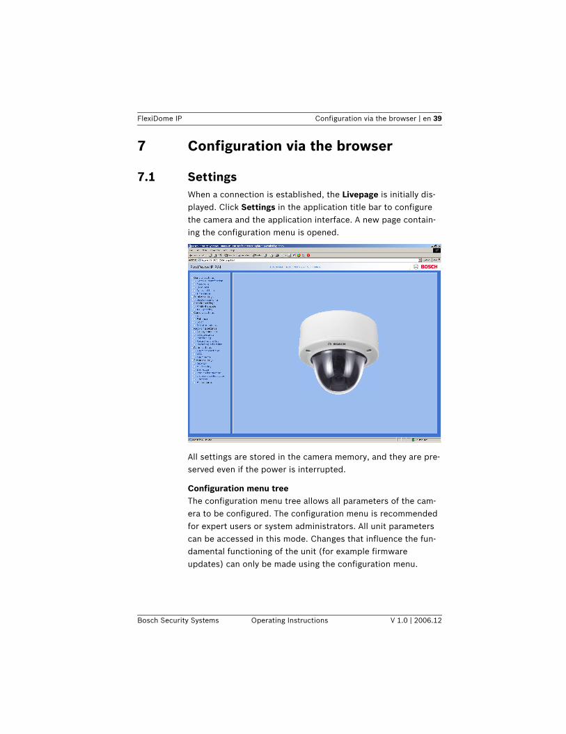
7 Configuration via the browser
7.1 SettingsWhen a connection is established, the Livepage is initially dis-played. Click Settings in the application title bar to configure the camera and the application interface. A new page contain-ing the configuration menu is opened.
All settings are stored in the camera memory, and they are pre-served even if the power is interrupted.
Configuration menu treeThe configuration menu tree allows all parameters of the cam-era to be configured. The configuration menu is recommended for expert users or system administrators. All unit parameters can be accessed in this mode. Changes that influence the fun-damental functioning of the unit (for example firmware updates) can only be made using the configuration menu.
40 en | Configuration via the browser FlexiDome IP
V 1.0 | 2006.12 Operating Instructions Bosch Security Systems
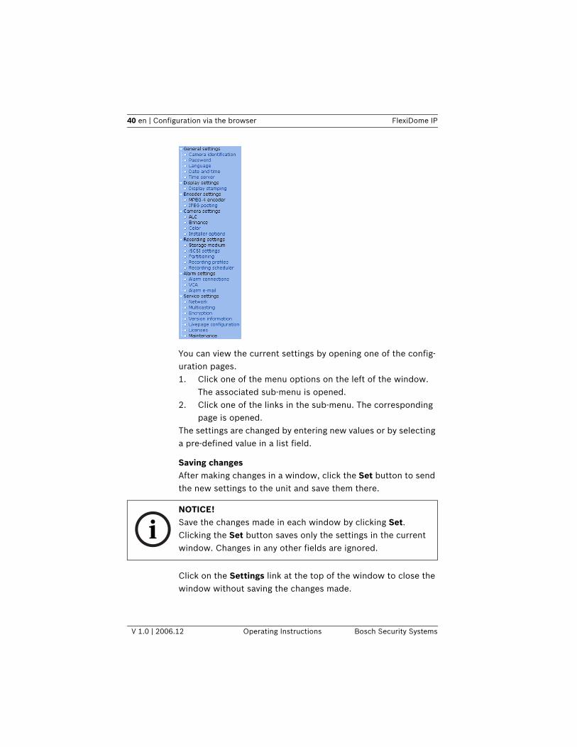
You can view the current settings by opening one of the config-uration pages. 1. Click one of the menu options on the left of the window.
The associated sub-menu is opened.2. Click one of the links in the sub-menu. The corresponding
page is opened.The settings are changed by entering new values or by selecting a pre-defined value in a list field.
Saving changesAfter making changes in a window, click the Set button to send the new settings to the unit and save them there.
Click on the Settings link at the top of the window to close the window without saving the changes made.
iNOTICE! Save the changes made in each window by clicking Set. Clicking the Set button saves only the settings in the current window. Changes in any other fields are ignored.
FlexiDome IP Configuration via the browser | en 41
Bosch Security Systems Operating Instructions V 1.0 | 2006.12
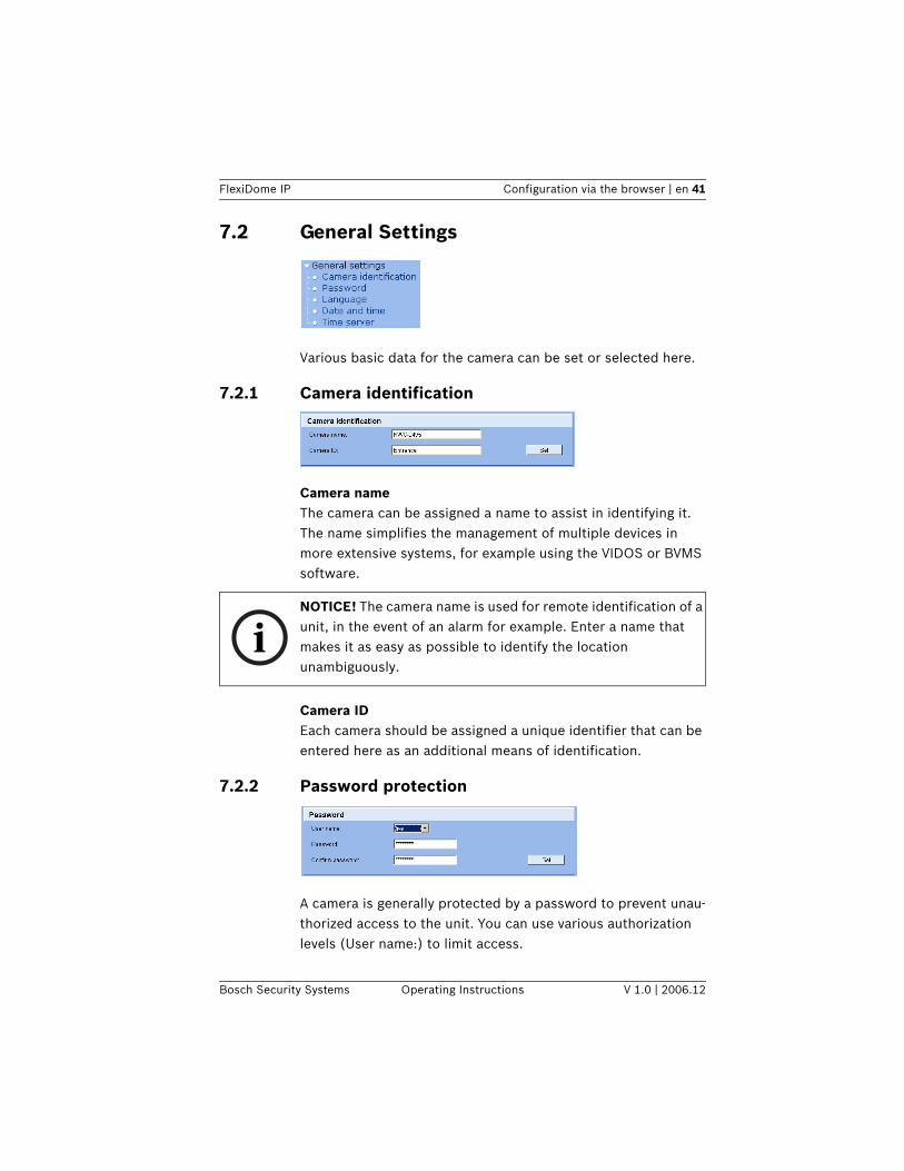
7.2 General Settings
Various basic data for the camera can be set or selected here.
7.2.1 Camera identification
Camera nameThe camera can be assigned a name to assist in identifying it. The name simplifies the management of multiple devices in more extensive systems, for example using the VIDOS or BVMS software.
Camera IDEach camera should be assigned a unique identifier that can be entered here as an additional means of identification.
7.2.2 Password protection
A camera is generally protected by a password to prevent unau-thorized access to the unit. You can use various authorization levels (User name:) to limit access.
iNOTICE! The camera name is used for remote identification of a unit, in the event of an alarm for example. Enter a name that makes it as easy as possible to identify the location unambiguously.
42 en | Configuration via the browser FlexiDome IP
V 1.0 | 2006.12 Operating Instructions Bosch Security Systems
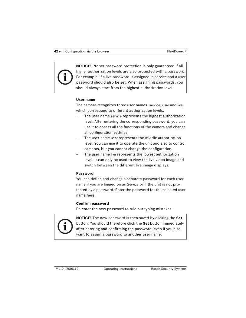
User nameThe camera recognizes three user names: service, user and live, which correspond to different authorization levels.– The user name service represents the highest authorization
level. After entering the corresponding password, you can use it to access all the functions of the camera and change all configuration settings.
– The user name user represents the middle authorization level. You can use it to operate the unit and also to control cameras, but you cannot change the configuration.
– The user name live represents the lowest authorization level. It can only be used to view the live video image and switch between the different live image displays.
PasswordYou can define and change a separate password for each user name if you are logged on as Service or if the unit is not pro-tected by a password. Enter the password for the selected user name here.
Confirm passwordRe-enter the new password to rule out typing mistakes.
iNOTICE! Proper password protection is only guaranteed if all higher authorization levels are also protected with a password. For example, if a live password is assigned, a service and a user password should also be set. When assigning passwords, you should always start from the highest authorization level.
iNOTICE! The new password is then saved by clicking the Set button. You should therefore click the Set button immediately after entering and confirming the password, even if you also want to assign a password to another user name.
FlexiDome IP Configuration via the browser | en 43
Bosch Security Systems Operating Instructions V 1.0 | 2006.12
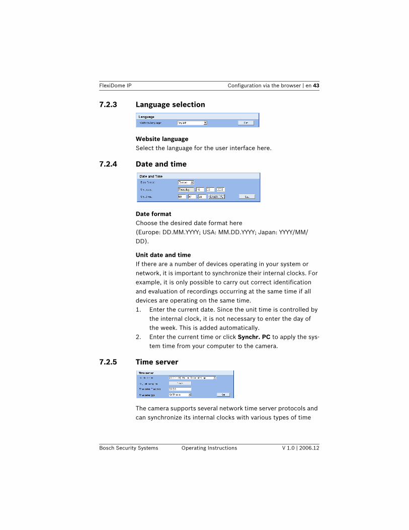
7.2.3 Language selection
Website languageSelect the language for the user interface here.
7.2.4 Date and time
Date formatChoose the desired date format here(Europe: DD.MM.YYYY; USA: MM.DD.YYYY; Japan: YYYY/MM/DD).
Unit date and timeIf there are a number of devices operating in your system or network, it is important to synchronize their internal clocks. For example, it is only possible to carry out correct identification and evaluation of recordings occurring at the same time if all devices are operating on the same time. 1. Enter the current date. Since the unit time is controlled by
the internal clock, it is not necessary to enter the day of the week. This is added automatically.
2. Enter the current time or click Synchr. PC to apply the sys-tem time from your computer to the camera.
7.2.5 Time server
The camera supports several network time server protocols and can synchronize its internal clocks with various types of time
44 en | Configuration via the browser FlexiDome IP
V 1.0 | 2006.12 Operating Instructions Bosch Security Systems
servers. The device calls up the time signal automatically once every minute.
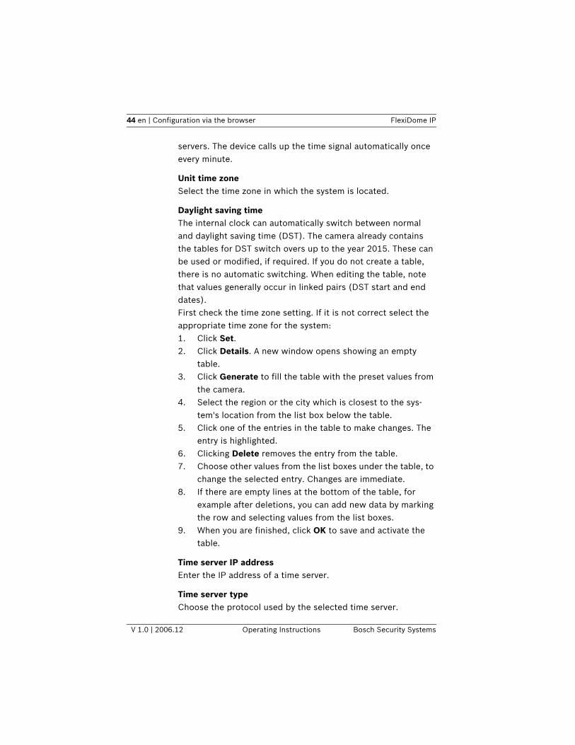
Unit time zoneSelect the time zone in which the system is located.
Daylight saving timeThe internal clock can automatically switch between normal and daylight saving time (DST). The camera already contains the tables for DST switch overs up to the year 2015. These can be used or modified, if required. If you do not create a table, there is no automatic switching. When editing the table, note that values generally occur in linked pairs (DST start and end dates).First check the time zone setting. If it is not correct select the appropriate time zone for the system:1. Click Set.2. Click Details. A new window opens showing an empty
table.3. Click Generate to fill the table with the preset values from
the camera.4. Select the region or the city which is closest to the sys-
tem's location from the list box below the table.5. Click one of the entries in the table to make changes. The
entry is highlighted.6. Clicking Delete removes the entry from the table.7. Choose other values from the list boxes under the table, to
change the selected entry. Changes are immediate.8. If there are empty lines at the bottom of the table, for
example after deletions, you can add new data by marking the row and selecting values from the list boxes.
9. When you are finished, click OK to save and activate the table.
Time server IP addressEnter the IP address of a time server.
Time server typeChoose the protocol used by the selected time server.
FlexiDome IP Configuration via the browser | en 45
Bosch Security Systems Operating Instructions V 1.0 | 2006.12
It is recommended that you choose the SNTP server protocol. This protocol provides higher accuracy and is required for cer-tain applications, as well as for future additions.Choose Time server, if the server uses RFC 868 as protocol.
7.3 Display Settings
7.3.1 Display stamping
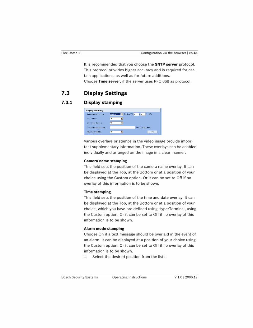
Various overlays or stamps in the video image provide impor-tant supplementary information. These overlays can be enabled individually and arranged on the image in a clear manner.
Camera name stampingThis field sets the position of the camera name overlay. It can be displayed at the Top, at the Bottom or at a position of your choice using the Custom option. Or it can be set to Off if no overlay of this information is to be shown.
Time stampingThis field sets the position of the time and date overlay. It can be displayed at the Top, at the Bottom or at a position of your choice, which you have pre-defined using HyperTerminal, using the Custom option. Or it can be set to Off if no overlay of this information is to be shown.
Alarm mode stampingChoose On if a text message should be overlaid in the event of an alarm. It can be displayed at a position of your choice using the Custom option. Or it can be set to Off if no overlay of this information is to be shown.1. Select the desired position from the lists.
46 en | Configuration via the browser FlexiDome IP
V 1.0 | 2006.12 Operating Instructions Bosch Security Systems
– If you have selected the Custom option, additional fields are displayed to specify the exact position (Position (XY):).
2. In the Position (XY): fields enter the values for the desired position.
Displayed alarm messageEnter the message to be displayed for an alarm. It can contain up to 31 characters.
Video watermarkingChoose On if the video images transmitted are to be water-marked. After activation, all images are marked with a small green rectangle. A red rectangle indicates that the sequence (live or saved) has been manipulated.
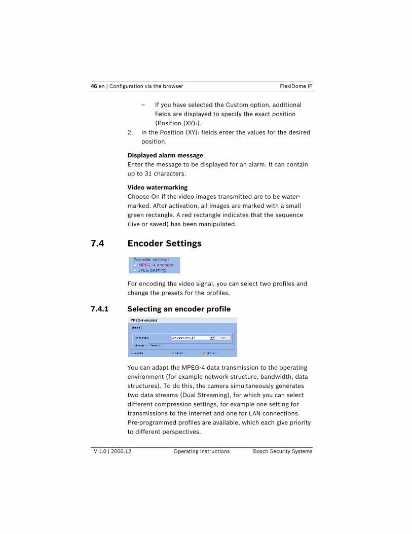
7.4 Encoder Settings
For encoding the video signal, you can select two profiles and change the presets for the profiles.
7.4.1 Selecting an encoder profile
You can adapt the MPEG-4 data transmission to the operating environment (for example network structure, bandwidth, data structures). To do this, the camera simultaneously generates two data streams (Dual Streaming), for which you can select different compression settings, for example one setting for transmissions to the Internet and one for LAN connections.Pre-programmed profiles are available, which each give priority to different perspectives.
FlexiDome IP Configuration via the browser | en 47
Bosch Security Systems Operating Instructions V 1.0 | 2006.12
– Profile 1: Low bandwidth (CIF)High quality for low bandwidth connections, resolution 352 × 288/240 pixels
– Profile 2: Low delay (2/3 D1)High quality with low delay, resolution 464 × 576/480 pix-els
– Profile 3: High resolution (4CIF/D1)High resolution for high bandwidth connections, resolution 704 × 576/480 pixels
– Profile 4: DSLFor DSL connections at 500 kBit/s, resolution 352 × 288/240 pixels
– Profile 5: ISDN (2B)For ISDN connections via two B channels, resolution 352 × 288/240 pixels
– Profile 6: ISDN (1B)For ISDN connections via one B channel, resolution 352 × 288/240 pixels
– Profile 7: ModemFor analog modem connections at 20 kBit/s, resolution 352 × 288/240 pixels
– Profile 8: GSMFor GSM connections at 9,600 baud, resolution 176 × 144/120 pixels
Active profileHere you can select the desired profile for each of the two streams. You will see a preview for each data stream in the right section of the window. The preview of the data stream currently selected is marked by a frame. Various additional items of infor-mation regarding data transmission are displayed and continu-ally updated above the previews.1. Click on a tab to select the associated stream.2. Select the desired setting from the list.
48 en | Configuration via the browser FlexiDome IP
V 1.0 | 2006.12 Operating Instructions Bosch Security Systems
Preview forSelect which video data stream should be displayed in the pre-views. You can deactivate the display of the video images if the performance of the computer is affected too strongly by the decoding of the data streams.– Check the box for the required data stream.
7.4.2 Changing profiles
You can change individual parameter values within a profile and the name. You can switch between profiles by clicking the asso-ciated tabs.
iNOTICE! Stream 2 is always transmitted for alarm connections and automatic connections. Take this into account when assigning the profile.
iNOTICE! The profiles are rather complex. They include a number of parameters that interact with one another. Therefore it is generally best to use the default profiles. The profiles should only be changed if you are completely familiar with all the configuration options.
iNOTICE! The parameters as a group constitute a profile and are dependent on one another. If you enter a setting outside the allowed range for a parameter, the nearest valid value is substituted when the settings are saved.
FlexiDome IP Configuration via the browser | en 49
Bosch Security Systems Operating Instructions V 1.0 | 2006.12
Profile nameYou can enter a new name for the profile here. The name is then displayed in the list of available profiles in the Active encoder profile: field.
Target data rateTo optimize utilization of the bandwidth in your network, you can limit the data rate for the camera. The target data rate should be set according to the desired picture quality for typi-cal scenes with no excessive motion. For complex images or frequent changes of image content due to frequent movements, this limit can temporarily be exceeded as far as the value you enter in the Max. data rate: field.
Encoding intervalThe figure selected here determines the interval at which images are encoded and transmitted. For example, entering 4 means that only every fourth image is encoded, the following three images are skipped – this can be particularly advanta-geous with low bandwidths. The image rate in IPS (Images Per Second) is displayed next to the text block.
Video resolutionHere, you can select the desired resolution for the MPEG-4 video image. The following resolutions are available:– QCIF 176 × 144/120 pixels– CIF 352 × 288/240 pixels– 1/2 D1 352 × 576/480 pixels– 2CIF 704 × 288/240 pixels– 4CIF/D1 704 × 576/480 pixels– 2/3 D1 464 × 576/480 pixels
DefaultClick Default to return the profile to the factory default values.
DetailsClick Details to display further settings for image quality and communication parameters. These settings require familiarity
50 en | Configuration via the browser FlexiDome IP
V 1.0 | 2006.12 Operating Instructions Bosch Security Systems
with MPEG and video encoding standards. Incorrect settings could result in useless video images.
Max. data rateThis maximum data rate is not exceeded under any circum-stances. Depending on the video quality settings for the I- and P-frames this can result in the skipping of individual images.The value entered here should be at least 10% higher than the value entered in the Target data rate field.
P-frame video qualityThis setting allows you to adjust the image quality of the P-frames depending on the movement within the image. The Auto option automatically adjusts to the optimum relationship between movement and image definition (focus). Selecting Manual allows you to set a value between 4 and 31 on a slide bar. The value 4 represents the best quality with, if necessary, a lower frame refresh rate depending on the settings for the max-imum data rate. A value of 31 results in a very high refresh rate and lower image quality.
I-frame video qualityThis setting allows you to adjust the image quality of the I-frames. The Auto option automatically adjusts the quality to the settings for the P-frame video quality. Selecting Manual allows you to set a value between 4 and 31 on a slide bar. The value 4 represents the best quality with, if necessary, a lower frame refresh rate depending on the settings for the maximum data rate. A value of 31 results in a very high refresh rate and lower image quality.
I-frame distanceThis parameter determines the number of inter-coded frames between two I-frames.
FlexiDome IP Configuration via the browser | en 51
Bosch Security Systems Operating Instructions V 1.0 | 2006.12
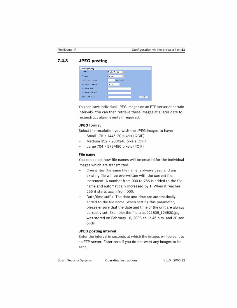
7.4.3 JPEG posting
You can save individual JPEG images on an FTP server at certain intervals. You can then retrieve these images at a later date to reconstruct alarm events if required.
JPEG formatSelect the resolution you wish the JPEG images to have:– Small 176 × 144/120 pixels (QCIF)– Medium 352 × 288/240 pixels (CIF)– Large 704 × 576/480 pixels (4CIF)
File nameYou can select how file names will be created for the individual images which are transmitted.– Overwrite: The same file name is always used and any
existing file will be overwritten with the current file.– Increment: A number from 000 to 255 is added to the file
name and automatically increased by 1. When it reaches 255 it starts again from 000.
– Date/time suffix: The date and time are automatically added to the file name. When setting this parameter, please ensure that the date and time of the unit are always correctly set. Example: the file snap021606_124530.jpg was stored on February 16, 2006 at 12.45 p.m. and 30 sec-onds.
JPEG posting intervalEnter the interval in seconds at which the images will be sent to an FTP server. Enter zero if you do not want any images to be sent.
52 en | Configuration via the browser FlexiDome IP
V 1.0 | 2006.12 Operating Instructions Bosch Security Systems
FTP server IP addressEnter the IP address of the FTP server on which you wish to save the JPEG images.
FTP server loginEnter your login name for the FTP server.
FTP server passwordEnter the password that gives you access to the FTP server.
Path on FTP serverEnter the exact path on which you wish to post the images on the FTP server.
Post JPEG from cameraCheck the box to activate one or more camera inputs for the JPEG image. An enabled camera input is indicated by a check mark.
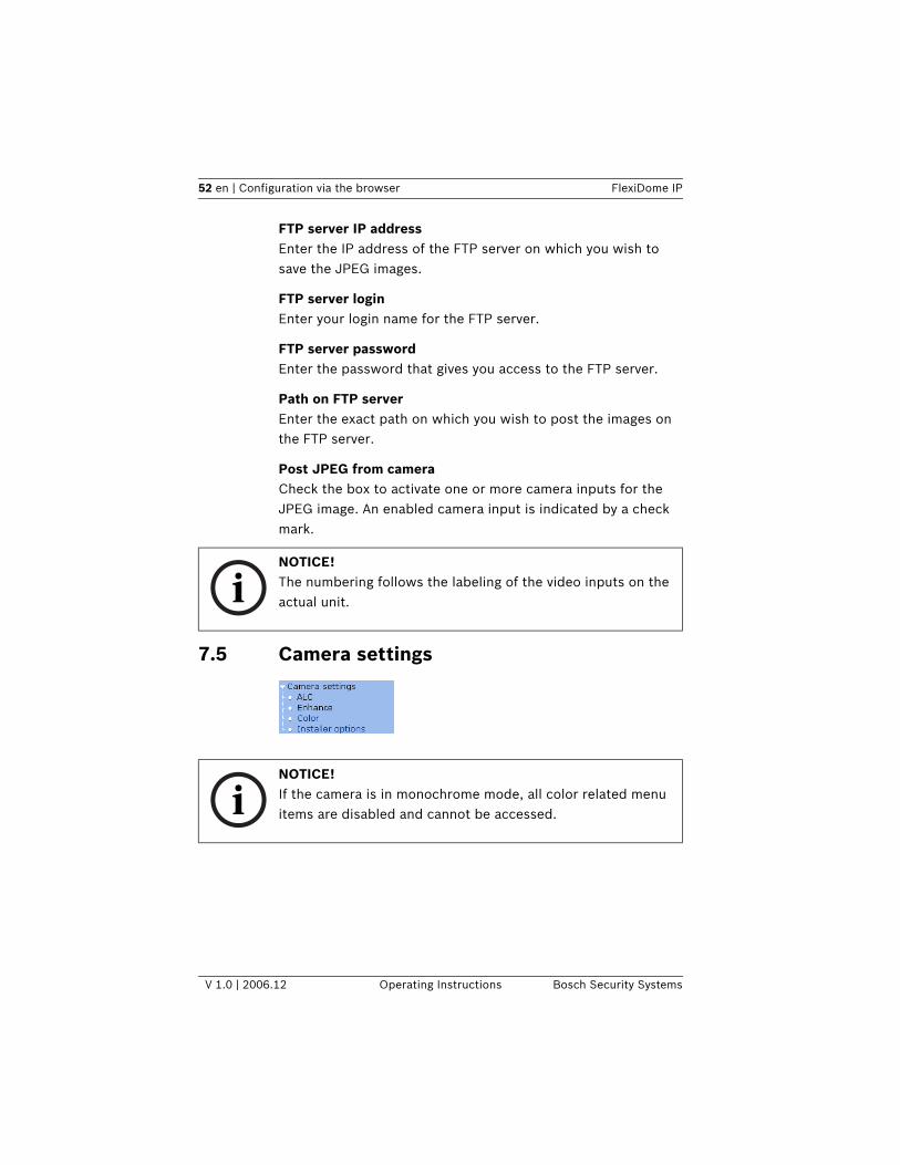
7.5 Camera settings
iNOTICE! The numbering follows the labeling of the video inputs on the actual unit.
iNOTICE! If the camera is in monochrome mode, all color related menu items are disabled and cannot be accessed.
FlexiDome IP Configuration via the browser | en 53
Bosch Security Systems Operating Instructions V 1.0 | 2006.12
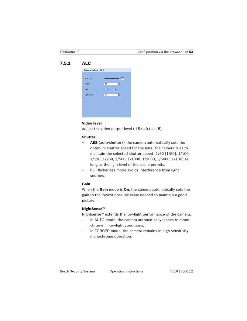
7.5.1 ALC
Video levelAdjust the video output level (-15 to 0 to +15).
Shutter– AES (auto-shutter) - the camera automatically sets the
optimum shutter speed for the lens. The camera tries to maintain the selected shutter speed (1/60 [1/50], 1/100, 1/120, 1/250, 1/500, 1/1000, 1/2000, 1/5000, 1/10K) as long as the light level of the scene permits.
– FL - flickerless mode avoids interference from light sources.
GainWhen the Gain mode is On, the camera automatically sets the gain to the lowest possible value needed to maintain a good picture.
NightSense™Nightsense™ extends the low-light performance of the camera. – In AUTO mode, the camera automatically inches to mono-
chrome in low-light conditions. – In FORCED mode, the camera remains in high-sensitivity
monochrome operation.
54 en | Configuration via the browser FlexiDome IP
V 1.0 | 2006.12 Operating Instructions Bosch Security Systems
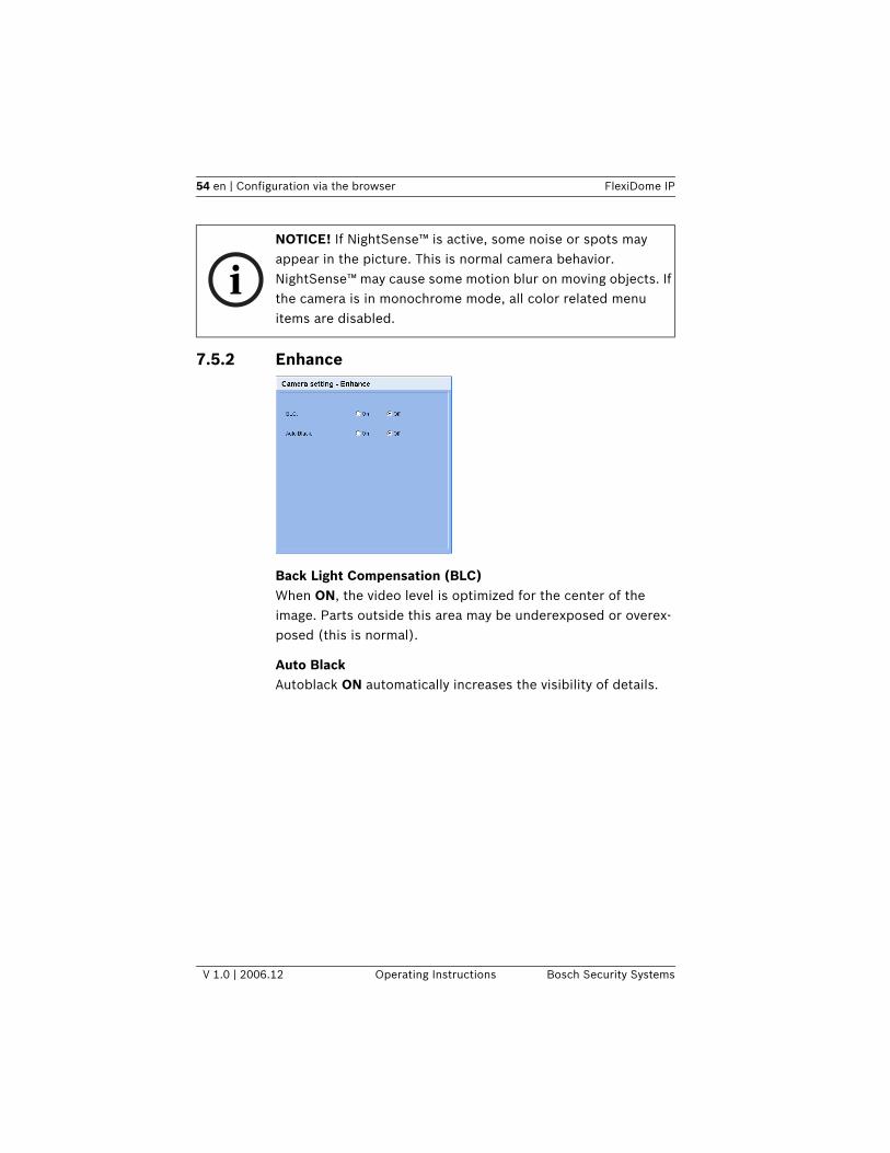
7.5.2 Enhance
Back Light Compensation (BLC)When ON, the video level is optimized for the center of the image. Parts outside this area may be underexposed or overex-posed (this is normal).
Auto BlackAutoblack ON automatically increases the visibility of details.
iNOTICE! If NightSense™ is active, some noise or spots may appear in the picture. This is normal camera behavior. NightSense™ may cause some motion blur on moving objects. If the camera is in monochrome mode, all color related menu items are disabled.
FlexiDome IP Configuration via the browser | en 55
Bosch Security Systems Operating Instructions V 1.0 | 2006.12
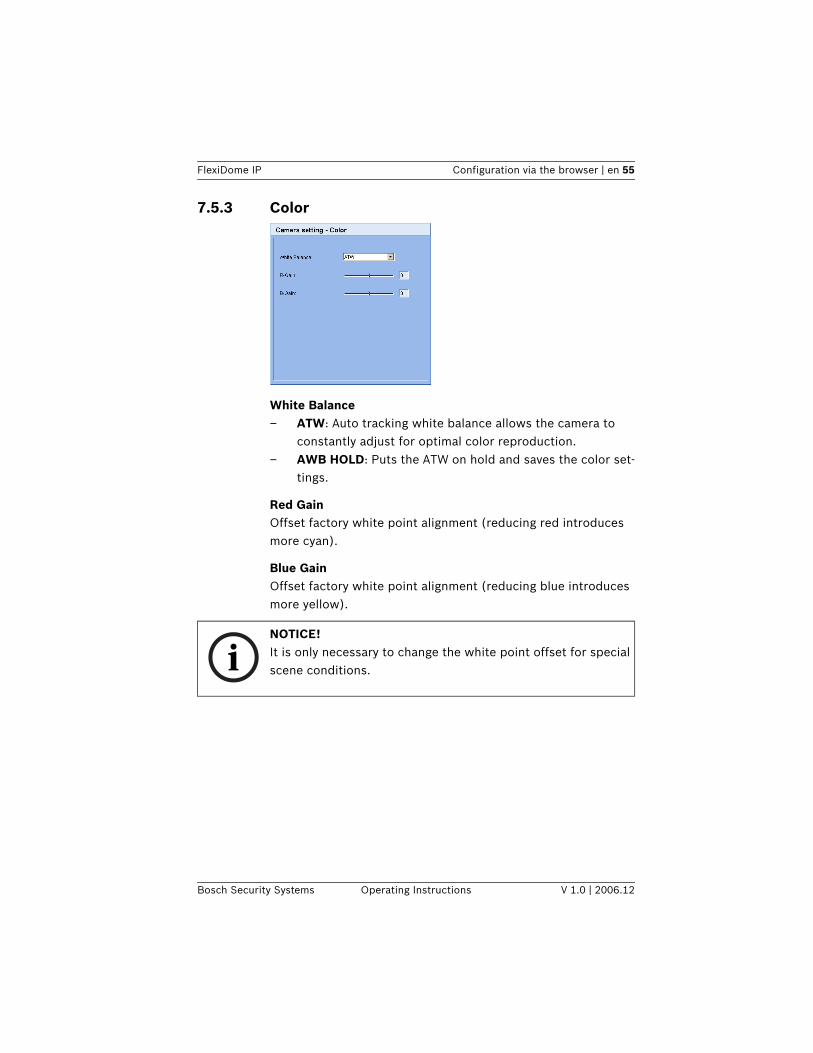
7.5.3 Color
White Balance– ATW: Auto tracking white balance allows the camera to
constantly adjust for optimal color reproduction. – AWB HOLD: Puts the ATW on hold and saves the color set-
tings.
Red GainOffset factory white point alignment (reducing red introduces more cyan).
Blue GainOffset factory white point alignment (reducing blue introduces more yellow).
iNOTICE! It is only necessary to change the white point offset for special scene conditions.
56 en | Configuration via the browser FlexiDome IP
V 1.0 | 2006.12 Operating Instructions Bosch Security Systems
7.5.4 Installer options
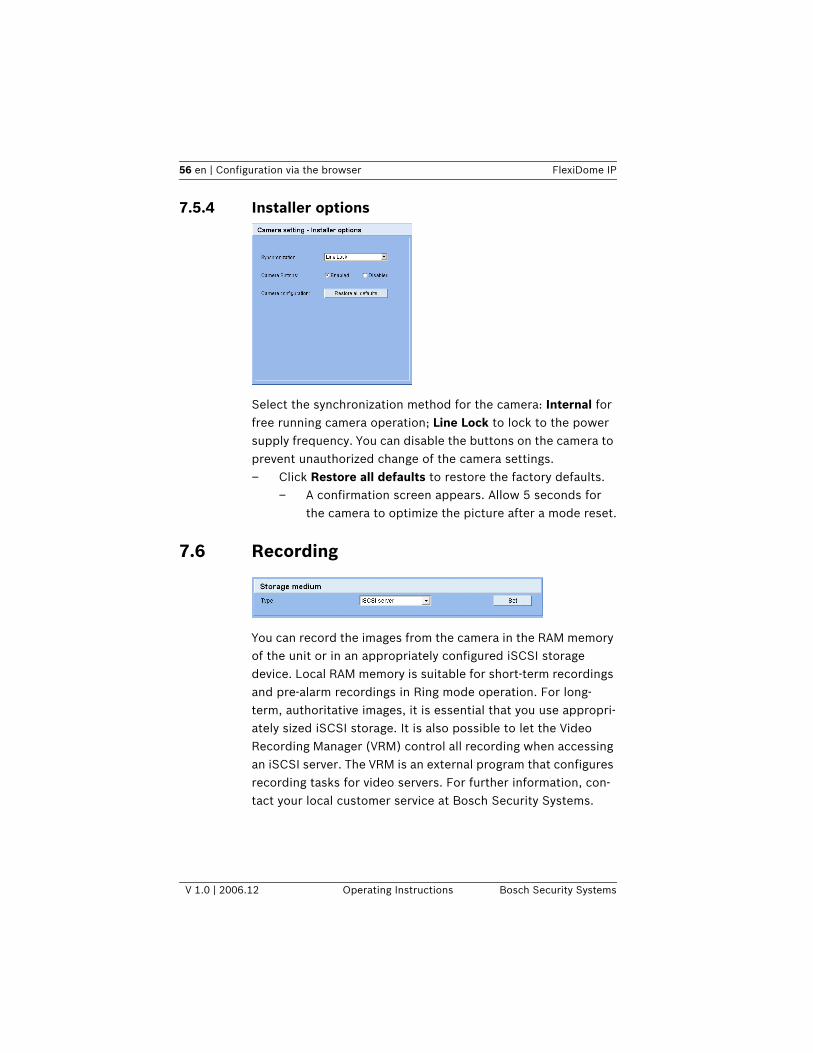
Select the synchronization method for the camera: Internal for free running camera operation; Line Lock to lock to the power supply frequency. You can disable the buttons on the camera to prevent unauthorized change of the camera settings. – Click Restore all defaults to restore the factory defaults.
– A confirmation screen appears. Allow 5 seconds for the camera to optimize the picture after a mode reset.
7.6 Recording
You can record the images from the camera in the RAM memory of the unit or in an appropriately configured iSCSI storage device. Local RAM memory is suitable for short-term recordings and pre-alarm recordings in Ring mode operation. For long-term, authoritative images, it is essential that you use appropri-ately sized iSCSI storage. It is also possible to let the Video Recording Manager (VRM) control all recording when accessing an iSCSI server. The VRM is an external program that configures recording tasks for video servers. For further information, con-tact your local customer service at Bosch Security Systems.
FlexiDome IP Configuration via the browser | en 57
Bosch Security Systems Operating Instructions V 1.0 | 2006.12
7.6.1 TypeSelect the desired storage medium to subsequently configure the recording parameters.
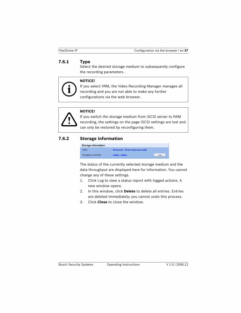
7.6.2 Storage information
The status of the currently selected storage medium and the data throughput are displayed here for information. You cannot change any of these settings.1. Click Log to view a status report with logged actions. A
new window opens.2. In this window, click Delete to delete all entries. Entries
are deleted immediately; you cannot undo this process.3. Click Close to close the window.
iNOTICE! If you select VRM, the Video Recording Manager manages all recording and you are not able to make any further configurations via the web browser.
!NOTICE! If you switch the storage medium from iSCSI server to RAM recording, the settings on the page iSCSI settings are lost and can only be restored by reconfiguring them.
58 en | Configuration via the browser FlexiDome IP
V 1.0 | 2006.12 Operating Instructions Bosch Security Systems
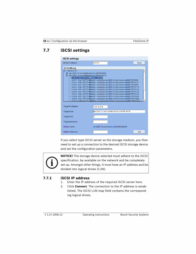
7.7 iSCSI settings
If you select type iSCSI server as the storage medium, you then need to set up a connection to the desired iSCSI storage device and set the configuration parameters.
7.7.1 iSCSI IP address1. Enter the IP address of the required iSCSI server here.2. Click Connect. The connection to the IP address is estab-
lished. The iSCSI LUN map field contains the correspond-ing logical drives.
iNOTICE! The storage device selected must adhere to the iSCSI specification, be available on the network and be completely set up. Amongst other things, it must have an IP address and be divided into logical drives (LUN).
FlexiDome IP Configuration via the browser | en 59
Bosch Security Systems Operating Instructions V 1.0 | 2006.12
7.7.2 iSCSI LUN mapThe LUN map displays the logical drives configured for the iSCSI storage device. The current user is displayed for each drive.1. Double-click a free drive (LUN). The associated information
is called up and automatically displayed in the fields below the map.
2. If the logical drive is password protected, you must first enter the password in the Target password field and click the Set button.
3. After entering all the settings in the relevant fields, click Set. The camera attempts to create a connection to the required drive using this data.
As soon as a connection has been established, the selected drive is used for recordings.
7.7.3 Target IP addressEnter the IP address of the required iSCSI server here.
7.7.4 Target nodeEnter the number of the iSCSI server target node.
7.7.5 Target LUNEnter the LUN of the required drive.
7.7.6 Target passwordIf the drive is password protected, enter the password.
iNOTICE! When the information cannot be read due to the network topology you must enter the data manually so that the camera can access the drive. In this case you should ensure that the entries correspond exactly with the configuration of the iSCSI device.
iNOTICE! You may not enter a new password. This is only possible by configuring the iSCSI storage device.
60 en | Configuration via the browser FlexiDome IP
V 1.0 | 2006.12 Operating Instructions Bosch Security Systems
7.7.7 Initiator nameThe initiator name is automatically displayed after a connection has been established.
7.7.8 Initiator extensionEnter the initiator extension. For the sake of clarity, you can enter a name or the existing extension with a comment, for example "– Camera 2".
7.7.9 Decoupling the drive usedEach drive can only be associated with one user. If a drive is already being used by another person, you can decouple the drive and connect the drive with the camera.1. Double-click a drive that is already being used in the LUN
map. You will see a warning message.2. Confirm the decoupling of the current user. The drive is
released and can be connected to the camera.
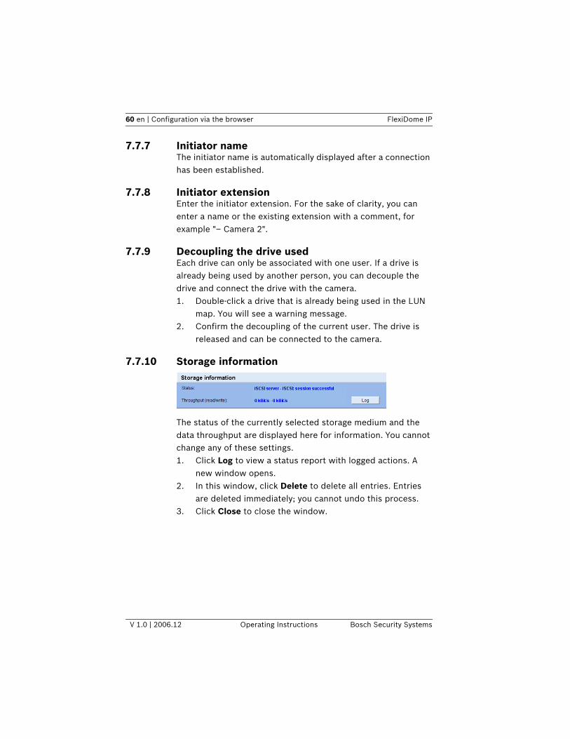
7.7.10 Storage information
The status of the currently selected storage medium and the data throughput are displayed here for information. You cannot change any of these settings.1. Click Log to view a status report with logged actions. A
new window opens.2. In this window, click Delete to delete all entries. Entries
are deleted immediately; you cannot undo this process.3. Click Close to close the window.
FlexiDome IP Configuration via the browser | en 61
Bosch Security Systems Operating Instructions V 1.0 | 2006.12
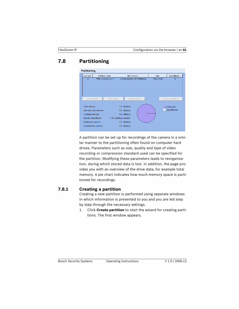
7.8 Partitioning
A partition can be set up for recordings of the camera in a simi-lar manner to the partitioning often found on computer hard drives. Parameters such as size, quality and type of video recording or compression standard used can be specified for the partition. Modifying these parameters leads to reorganiza-tion, during which stored data is lost. In addition, the page pro-vides you with an overview of the drive data; for example total memory. A pie chart indicates how much memory space is parti-tioned for recordings.
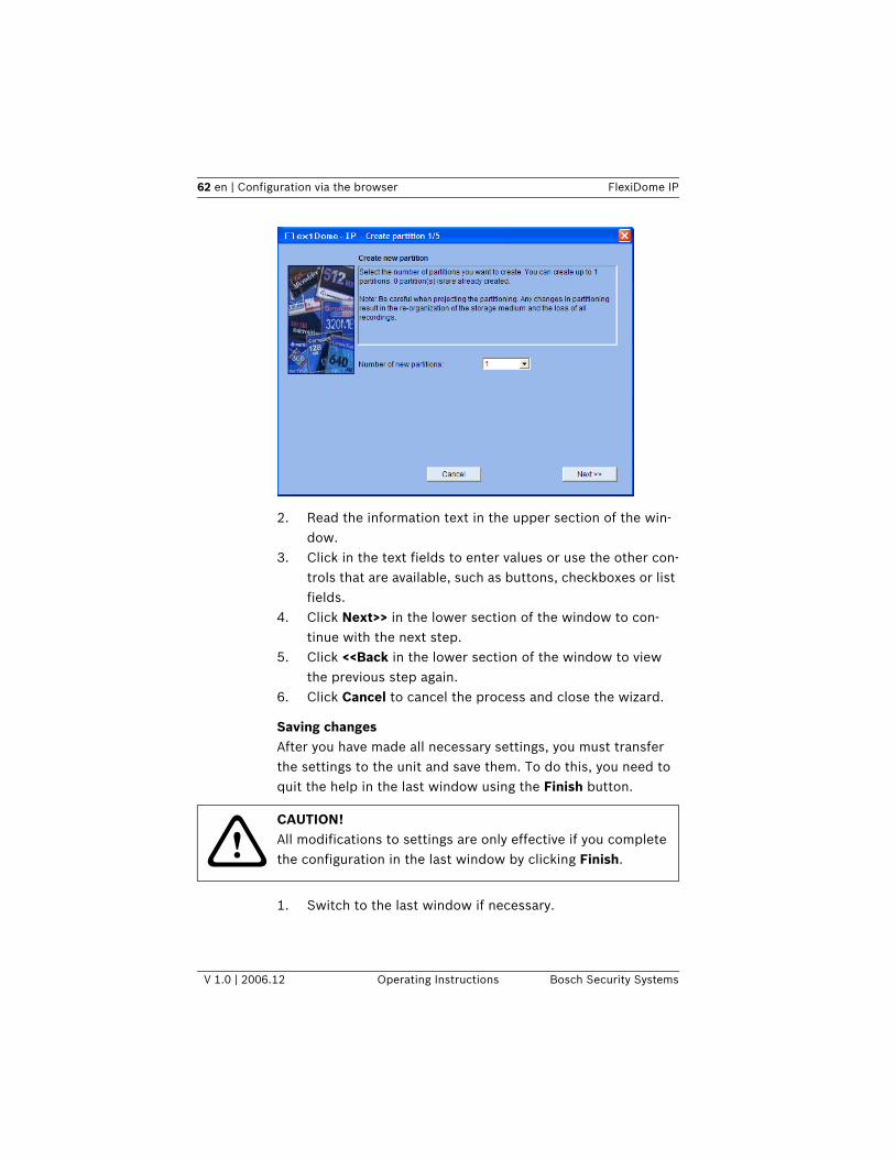
7.8.1 Creating a partitionCreating a new partition is performed using separate windows in which information is presented to you and you are led step by step through the necessary settings.1. Click Create partition to start the wizard for creating parti-
tions. The first window appears.
62 en | Configuration via the browser FlexiDome IP
V 1.0 | 2006.12 Operating Instructions Bosch Security Systems
.
2. Read the information text in the upper section of the win-dow.
3. Click in the text fields to enter values or use the other con-trols that are available, such as buttons, checkboxes or list fields.
4. Click Next>> in the lower section of the window to con-tinue with the next step.
5. Click <<Back in the lower section of the window to view the previous step again.
6. Click Cancel to cancel the process and close the wizard.
Saving changesAfter you have made all necessary settings, you must transfer the settings to the unit and save them. To do this, you need to quit the help in the last window using the Finish button.
1. Switch to the last window if necessary.
!CAUTION! All modifications to settings are only effective if you complete the configuration in the last window by clicking Finish.
FlexiDome IP Configuration via the browser | en 63
Bosch Security Systems Operating Instructions V 1.0 | 2006.12
2. Click Finish to complete the configuration. All settings are now transferred to the unit and subsequently become effective.
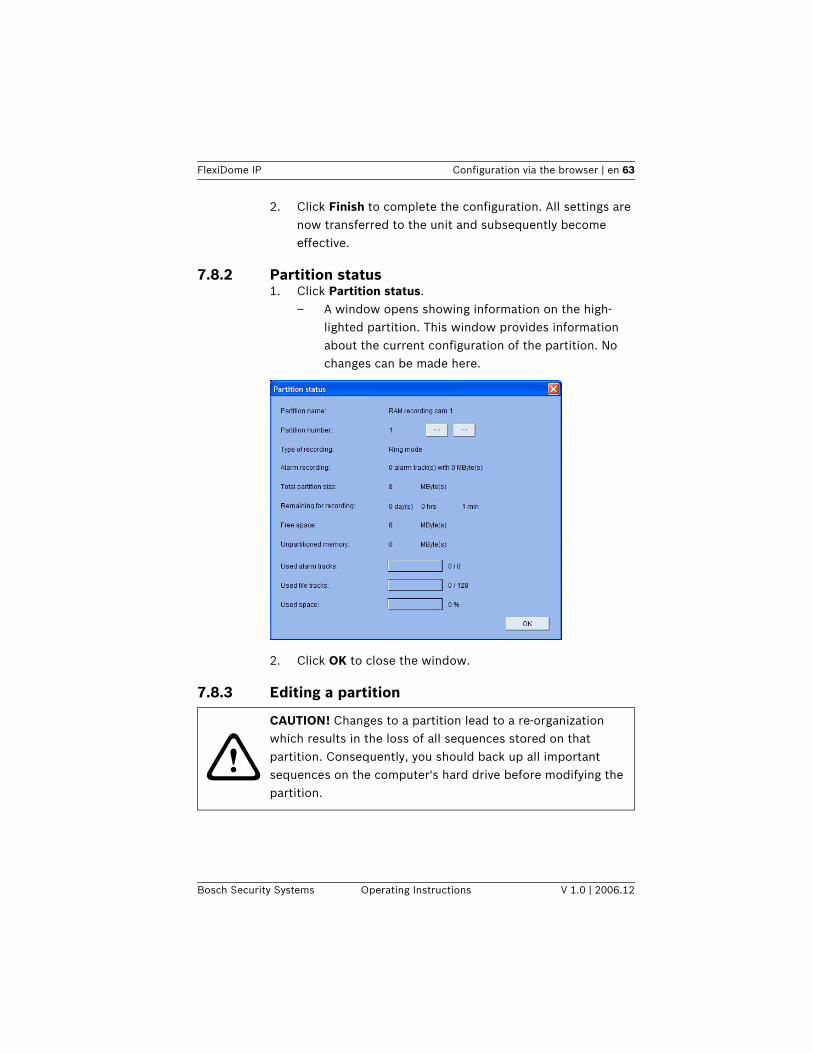
7.8.2 Partition status 1. Click Partition status.
– A window opens showing information on the high-lighted partition. This window provides information about the current configuration of the partition. No changes can be made here.
2. Click OK to close the window.
7.8.3 Editing a partition
!CAUTION! Changes to a partition lead to a re-organization which results in the loss of all sequences stored on that partition. Consequently, you should back up all important sequences on the computer's hard drive before modifying the partition.
64 en | Configuration via the browser FlexiDome IP
V 1.0 | 2006.12 Operating Instructions Bosch Security Systems
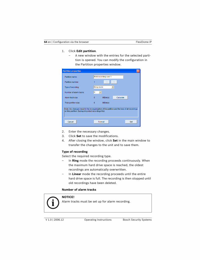
1. Click Edit partition. – A new window with the entries for the selected parti-
tion is opened. You can modify the configuration in the Partition properties window.
2. Enter the necessary changes.3. Click Set to save the modifications.4. After closing the window, click Set in the main window to
transfer the changes to the unit and to save them.
Type of recordingSelect the required recording type. – In Ring mode the recording proceeds continuously. When
the maximum hard drive space is reached, the oldest recordings are automatically overwritten.
– In Linear mode the recording proceeds until the entire hard drive space is full. The recording is then stopped until old recordings have been deleted.
Number of alarm tracks
iNOTICE! Alarm tracks must be set up for alarm recording.
FlexiDome IP Configuration via the browser | en 65
Bosch Security Systems Operating Instructions V 1.0 | 2006.12
The unit uses a special recording mode during alarm recording for optimal usage of storage capacity. As soon as a time gap for alarm recording begins, a recording is continuously made on one segment, which is the size of a complete alarm sequence (pre- and post-alarm time). This segment in the partition func-tions in a similar manner to a ring buffer and is overwritten until an alarm is actually triggered. Recording occurs on the segment only for the duration of the preset post-alarm time and a new segment is subsequently used in the same manner.Select the number of alarm tracks to be used in the partition. One alarm event can be recorded in each alarm track. Accord-ingly, the number of alarms entered can be recorded and archived. A partition can contain a maximum of 128 alarm recordings. If the Ring mode is set for a partition, the latest alarm recordings are always saved in the preset number. If the Linear mode is selected, the recording is stopped as soon as the total number of alarm tracks has been recorded.
Alarm track sizeThe size for an alarm track can be calculated according to vari-ous parameters. The calculated size applies to all alarm tracks for the partition.1. Click Calculate. A window opens.2. Select the appropriate setting for each parameter from the
list boxes.3. Click Set to accept the calculated value.
Format!You can delete all recordings in a partition at any time.
– Click Format! to delete all recordings in the current parti-tion.
!CAUTION! Check the recordings before deleting and back-up important sequences on the computer's hard drive.
66 en | Configuration via the browser FlexiDome IP
V 1.0 | 2006.12 Operating Instructions Bosch Security Systems
7.8.4 Deleting partitionsYou can delete a partition at any time.
1. Click Delete partition button to delete the highlighted par-tition. The line containing the associated number remains in the display, the partition name is deleted and the size is indicated as 0.
2. Click Set to transfer the changes to the unit and to save them.
7.9 Recording profileYou can define up to ten separate recording profiles. You then assign these to individual days or times of day in the recording scheduler. Modify the names of the recording profiles on the tabs in the Recording planner page.
!CAUTION! Deleting a partition leads to the entire hard drive being reorganized and loss of all sequences stored on the drive. Consequently, you should check the recordings before deleting any partition and back up important sequences on the computer's hard drive.
FlexiDome IP Configuration via the browser | en 67
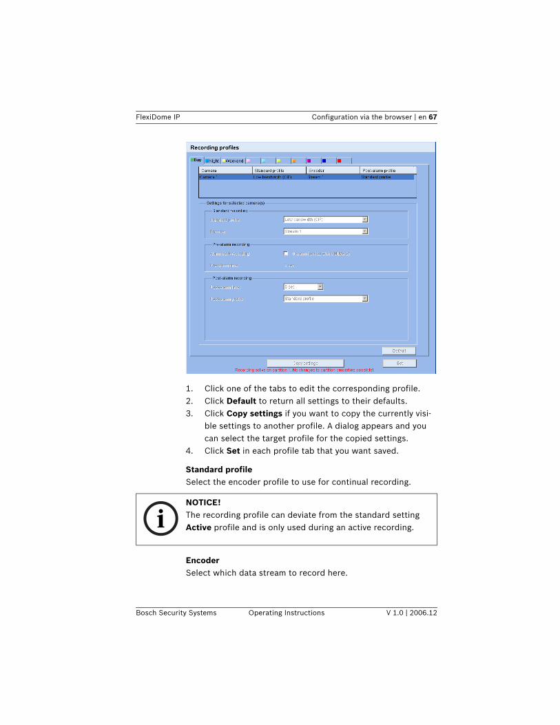
Bosch Security Systems Operating Instructions V 1.0 | 2006.12
1. Click one of the tabs to edit the corresponding profile.2. Click Default to return all settings to their defaults.3. Click Copy settings if you want to copy the currently visi-
ble settings to another profile. A dialog appears and you can select the target profile for the copied settings.
4. Click Set in each profile tab that you want saved.
Standard profileSelect the encoder profile to use for continual recording.
EncoderSelect which data stream to record here.
iNOTICE! The recording profile can deviate from the standard setting Active profile and is only used during an active recording.
68 en | Configuration via the browser FlexiDome IP
V 1.0 | 2006.12 Operating Instructions Bosch Security Systems
Alarm track recordingThis parameter is only active, if the alarm tracks have been con-figured. – Click the checkbox to activate alarm track recording. The
pre-alarm time gap is displayed automatically.
Post-alarm timeSelect the post-alarm time gap from the list box.
Post-alarm profileSelect the encoder profile to use for recording during the post-alarm time. The Standard profile option sets this to the same as the standard profile.
Motion detection/video alarmSelect the alarm type that is to trigger a recording.
FlexiDome IP Configuration via the browser | en 69
Bosch Security Systems Operating Instructions V 1.0 | 2006.12
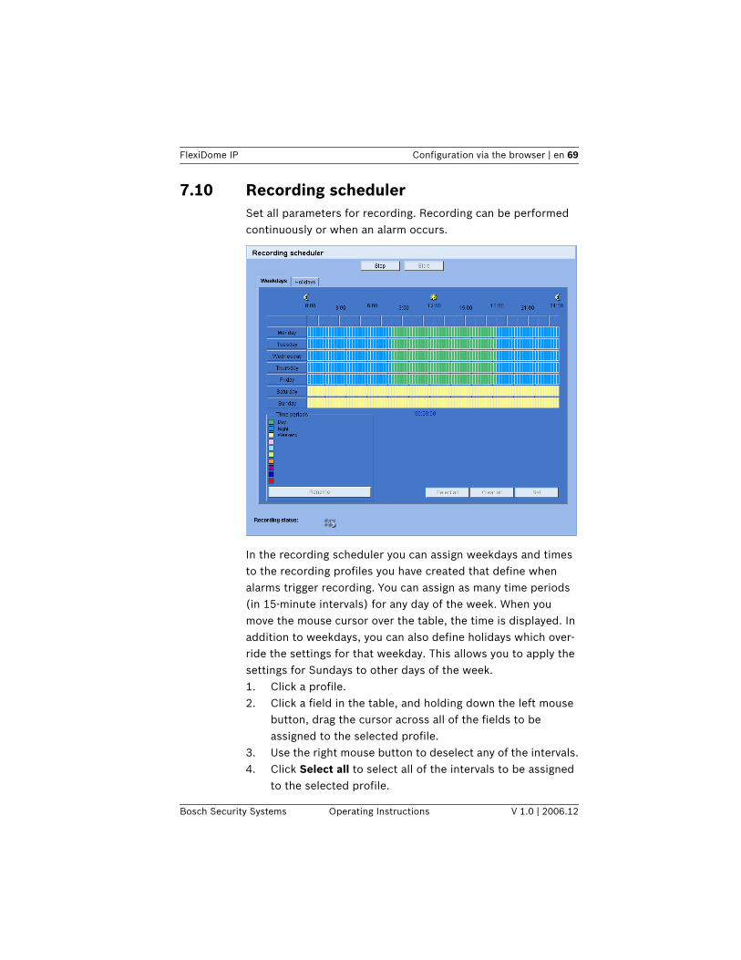
7.10 Recording schedulerSet all parameters for recording. Recording can be performed continuously or when an alarm occurs..
In the recording scheduler you can assign weekdays and times to the recording profiles you have created that define when alarms trigger recording. You can assign as many time periods (in 15-minute intervals) for any day of the week. When you move the mouse cursor over the table, the time is displayed. In addition to weekdays, you can also define holidays which over-ride the settings for that weekday. This allows you to apply the settings for Sundays to other days of the week. 1. Click a profile.2. Click a field in the table, and holding down the left mouse
button, drag the cursor across all of the fields to be assigned to the selected profile.
3. Use the right mouse button to deselect any of the intervals.4. Click Select all to select all of the intervals to be assigned
to the selected profile.
70 en | Configuration via the browser FlexiDome IP
V 1.0 | 2006.12 Operating Instructions Bosch Security Systems
5. Click Clear all to deselect all of the intervals.6. When you are finished, click Set to save the settings in the
device.
HolidaysYou can define holidays, which will override the settings for the normal weekly schedule. This allows you to apply the settings for Sundays to other days of the week.1. Click the Holidays tab. Days that have already been
defined are shown in the table.2. Click Add. This opens a new window.3. Select the desired date from the calendar. Drag the mouse
to select a range of dates. These are handled as a single entry in the table.
4. Click OK to accept the selection(s). The window closes.5. Assign the defined holidays to the recording profile as
described above.
Delete holidaysYou can delete user-defined holidays at any time.1. Click Delete in the Holidays tab. This opens a new win-
dow.2. Click the date to be deleted.3. Click OK. The selection is removed from the table and the
window closed.4. Repeat for any other dates to be deleted.
Profile namesYou can change the names of the recording profiles.1. Select a profile by clicking and then click Rename.2. Enter the desired name and click Rename again.
7.10.1 Activating recordingAfter configuration, you must activate the recording schedule and initiate recording. Once activated, the Recording profiles and the Recording scheduler are deactivated and the configura-tion cannot be modified. You can terminate recording at any time to modify the configuration.1. Click Start to activate the recording schedule.
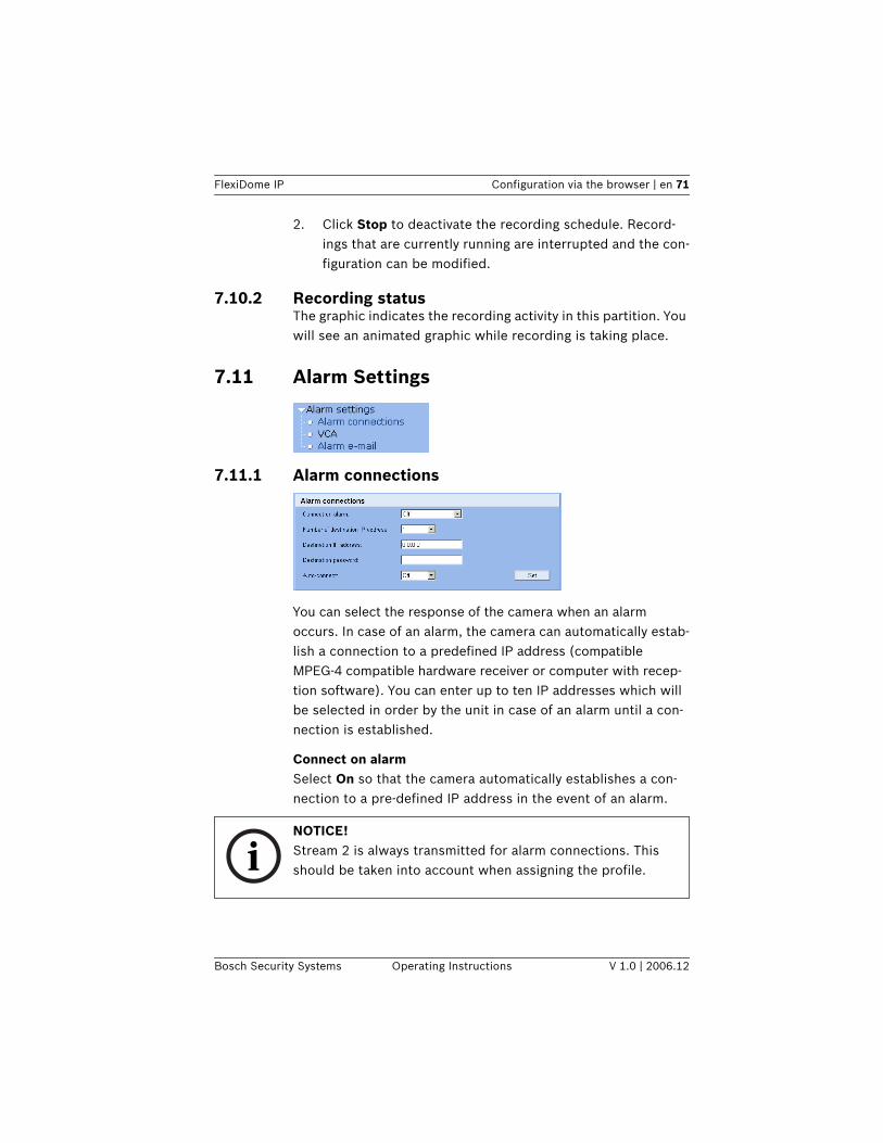
FlexiDome IP Configuration via the browser | en 71
Bosch Security Systems Operating Instructions V 1.0 | 2006.12
2. Click Stop to deactivate the recording schedule. Record-ings that are currently running are interrupted and the con-figuration can be modified.
7.10.2 Recording statusThe graphic indicates the recording activity in this partition. You will see an animated graphic while recording is taking place.
7.11 Alarm Settings
7.11.1 Alarm connections
You can select the response of the camera when an alarm occurs. In case of an alarm, the camera can automatically estab-lish a connection to a predefined IP address (compatible MPEG-4 compatible hardware receiver or computer with recep-tion software). You can enter up to ten IP addresses which will be selected in order by the unit in case of an alarm until a con-nection is established.
Connect on alarmSelect On so that the camera automatically establishes a con-nection to a pre-defined IP address in the event of an alarm.
iNOTICE! Stream 2 is always transmitted for alarm connections. This should be taken into account when assigning the profile.
72 en | Configuration via the browser FlexiDome IP
V 1.0 | 2006.12 Operating Instructions Bosch Security Systems
Number of destination IP addressHere you assign the numbering for the IP addresses to be con-tacted in the event of an alarm. The unit contacts the remote locations one after the other in the numbered sequence until a connection has been established.
Destination IP addressFor each number, enter the corresponding IP address for the desired remote location.
Destination passwordIf the remote location is password protected, enter the pass-word here.
Only ten passwords can be defined here. You can define a gen-eral password if more than ten connections are required, for example when connections are initiated by a controlling system such as VIDOS or BVMS. The camera connects to all devices protected by the same general password. To define a general password: 1. Select 10 in the Number of Destination IP-address list
box.2. Enter 0.0.0.0 in the Destination IP-address field.3. Enter the password in the Destination password field.4. Set the user password of all the devices to be connected
to this password.Setting destination 10 to the IP-address 0.0.0.0 overrides its function as the tenth address to try.
Destination portChoose the browser-port, depending on the network configura-tion. Port 443 for HTTPS connections is only available if the On option in SSL encryption is selected.
SSL encryption SSL encryption can be used to protect data, such as the pass-word used for establishing a connection. If you select On, only encrypted ports are available for the destination port. SSL encryption must be activated and configured on both sides of a
FlexiDome IP Configuration via the browser | en 73
Bosch Security Systems Operating Instructions V 1.0 | 2006.12
connection. The appropriate certificates must also have been uploaded (see “SSL certificate upload” on page 93). You can configure and activate encryption for media data (video, audio, metadata) on the Encryption page (see “Encryption” on page 86).
Auto-connectSelect On if an active connection should be re-established auto-matically to one of the previously specified IP addresses after each restart, connection breakdown or network failure.
iNOTICE! Stream 2 is always transmitted for automatic connections. This should be taken into account when assigning the profile.
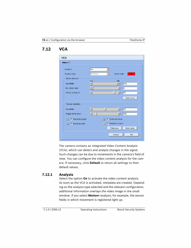
74 en | Configuration via the browser FlexiDome IP
V 1.0 | 2006.12 Operating Instructions Bosch Security Systems
7.12 VCA
The camera contains an integrated Video Content Analysis (VCA), which can detect and analyze changes in the signal. Such changes can be due to movements in the camera's field of view. You can configure the video content analysis for the cam-era. If necessary, click Default to return all settings to their default values.
7.12.1 AnalysisSelect the option On to activate the video content analysis.As soon as the VCA is activated, metadata are created. Depend-ing on the analysis type selected and the relevant configuration, additional information overlays the video image in the small window. If you select Motion+ analysis, for example, the sensor fields in which movement is registered light up.
FlexiDome IP Configuration via the browser | en 75
Bosch Security Systems Operating Instructions V 1.0 | 2006.12
7.12.2 Analysis typeSelect the required analysis algorithm. By default, only Motion+ is available – this offers a motion detector and essential recog-nition of tampering. The current alarm status is displayed for information purposes.
7.12.3 Motion detectorMotion detection is available for the Motion+ analysis type. For the detector to function, the following conditions must be met:– Analysis must be activated.– At least one sensor field must be activated.– The individual parameters must be configured to suit the
operating environment and the desired responses.– The sensitivity must be set to a value greater than zero.
7.12.4 SensitivitySensitivity is available for the Motion+ analysis type. The basic sensitivity of the motion detector can be adjusted for the envi-ronmental conditions to which the camera is subject. The sen-sor reacts to variations in the brightness of the video image.
iNOTICE! On the Livepage configuration page, you can enable additional information overlays for the live video image too (see “Livepage configuration” on page 88).
iNOTICE! Additional analysis algorithms with comprehensive functions such as IVMD are available from Bosch Security Systems.
iNOTICE! Reflections of light (off glass surfaces, etc.), switching lights on or off or changes in the light level caused by cloud movement on a sunny day can trigger unintended responses from the motion detector and generate false alarms. Run a series of tests at different times of the day and night to ensure that the video sensor is operating as intended.
76 en | Configuration via the browser FlexiDome IP
V 1.0 | 2006.12 Operating Instructions Bosch Security Systems
The darker the observation area, the higher the value that must be selected.
Min. object sizeYou can specify the number of sensor fields that a moving object must cover to generate an alarm. This setting prevents objects that are too small from triggering an alarm. A minimum value of 4 is recommended. This value corresponds to four sen-sor fields.
Global change %You can define the percentage of sensor fields that must regis-ter a change simultaneously before generating an alarm. This setting is independent of the sensor fields selected under Select area. This option allows you to detect, independently of motion alarms, manipulation of the orientation or location of a camera resulting from turning the camera mounting bracket, for instance.
Selecting the areaThe areas of the image to be monitored by the motion detector can be selected. The video image is subdivided into 858 square sensor fields. You can activate or deactivate each of these fields individually. If you wish to exclude particular regions of the camera's field of view from monitoring due to continuous move-ment (by a tree in the wind, etc.), the relevant fields can be deactivated.1. Click Select area to configure the sensor fields. A new win-
dow opens.2. If necessary, click Clear all first to clear the current selec-
tion (fields marked red).3. Left-click the fields to be activated. Activated fields are
marked red.4. If necessary, click Select all to select the entire video
frame for monitoring.5. Right-click any fields you wish to deactivate.6. Click OK to save the configuration.
FlexiDome IP Configuration via the browser | en 77
Bosch Security Systems Operating Instructions V 1.0 | 2006.12
7. Click the close button (X) in the window title bar to close the window without saving the changes.
7.12.5 Tamper detectionYou can detect the tampering of cameras and video cables by means of various options. Run a series of tests at different times of the day and night to ensure that the video sensor is operating as intended.
Sensitivity
The basic sensitivity of the tamper detection can be adjusted for the environmental conditions to which the camera is sub-ject. The algorithm reacts to the differences between the refer-ence image and the current video image. The darker the observation area, the higher the value that must be selected.
Trigger delayYou can set delayed alarm triggering. The alarm is only triggered after a set time interval in seconds has elapsed and then only if the triggering condition still exists. If the original condition has been restored before this time interval elapses, the alarm is not triggered. This allows you to avoid false alarms triggered by short-term changes, for example cleaning activities in the direct field of vision of the camera.
Scene too brightActivate this function if tampering associated with exposure to extreme light (for instance, shining a flashlight directly on the objective) should trigger an alarm. The average brightness of the scene provides a basis for recognition.
Scene too darkActivate this function if tampering associated with covering the objective (for instance, by spraying paint on it) should trigger
iNOTICE! This and the following parameter are only accessible if the reference check is activated.
78 en | Configuration via the browser FlexiDome IP
V 1.0 | 2006.12 Operating Instructions Bosch Security Systems
an alarm. The average brightness of the scene provides a basis for recognition.
Scene too noisyActivate this function if tampering associated with EMC inter-ference (noisy scene as the result of a strong interference sig-nal in the vicinity of the video lines) should trigger an alarm.
Reference checkYou can save a reference image that is continuously compared with the current video image. If the current video image in the marked areas differs from the reference image, an alarm is trig-gered. This allows you to detect tampering that would other-wise not be detected, for example if the camera is turned.1. Click Reference to save the currently visible video image
as a reference.2. Click Select area and select the areas in the reference
image that are to be monitored.3. Check the box Reference check to activate the on-going
check. The stored reference image is displayed in black and white below the current video image, and the selected areas are marked in red.
Selecting the areaYou can select the image areas in the reference image that are to be monitored. The video image is subdivided into 858 square fields. You can activate or deactivate each of these fields indi-vidually.
1. Click Select area to configure the sensor fields. A new win-dow will open.
2. If necessary, click Clear all first to clear the current selec-tion (fields marked red).
iNOTICE! Select only those areas for reference monitoring in which no movement takes place and that are always evenly lit, as false alarms could otherwise be triggered.
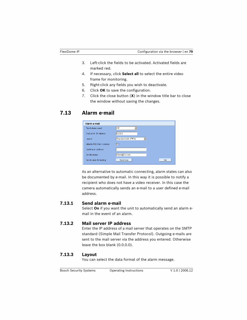
FlexiDome IP Configuration via the browser | en 79
Bosch Security Systems Operating Instructions V 1.0 | 2006.12
3. Left-click the fields to be activated. Activated fields are marked red.
4. If necessary, click Select all to select the entire video frame for monitoring.
5. Right-click any fields you wish to deactivate.6. Click OK to save the configuration.7. Click the close button (X) in the window title bar to close
the window without saving the changes.
7.13 Alarm e-mail
As an alternative to automatic connecting, alarm states can also be documented by e-mail. In this way it is possible to notify a recipient who does not have a video receiver. In this case the camera automatically sends an e-mail to a user defined e-mail address.
7.13.1 Send alarm e-mailSelect On if you want the unit to automatically send an alarm e-mail in the event of an alarm.
7.13.2 Mail server IP addressEnter the IP address of a mail server that operates on the SMTP standard (Simple Mail Transfer Protocol). Outgoing e-mails are sent to the mail server via the address you entered. Otherwise leave the box blank (0.0.0.0).
7.13.3 LayoutYou can select the data format of the alarm message.
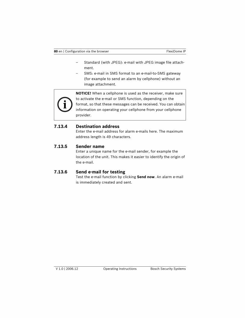
80 en | Configuration via the browser FlexiDome IP
V 1.0 | 2006.12 Operating Instructions Bosch Security Systems
– Standard (with JPEG): e-mail with JPEG image file attach-ment.
– SMS: e-mail in SMS format to an e-mail-to-SMS gateway (for example to send an alarm by cellphone) without an image attachment.
7.13.4 Destination addressEnter the e-mail address for alarm e-mails here. The maximum address length is 49 characters.
7.13.5 Sender nameEnter a unique name for the e-mail sender, for example the location of the unit. This makes it easier to identify the origin of the e-mail.
7.13.6 Send e-mail for testingTest the e-mail function by clicking Send now. An alarm e-mail is immediately created and sent.
iNOTICE! When a cellphone is used as the receiver, make sure to activate the e-mail or SMS function, depending on the format, so that these messages can be received. You can obtain information on operating your cellphone from your cellphone provider.
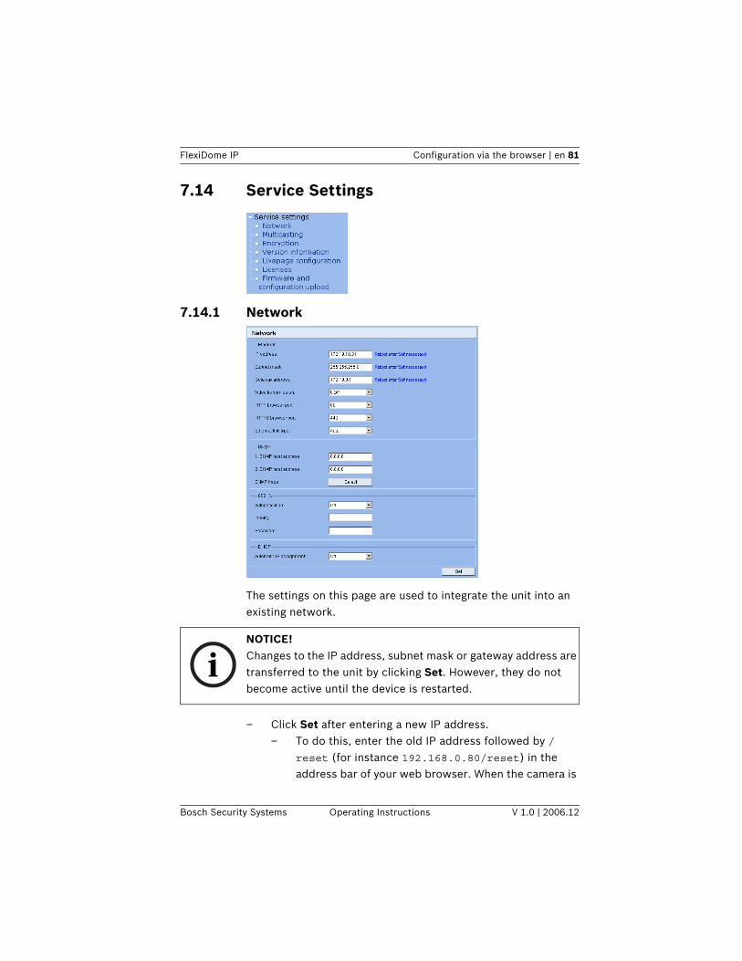
FlexiDome IP Configuration via the browser | en 81
Bosch Security Systems Operating Instructions V 1.0 | 2006.12
7.14 Service Settings
7.14.1 Network
The settings on this page are used to integrate the unit into an existing network.
– Click Set after entering a new IP address.– To do this, enter the old IP address followed by /
reset (for instance 192.168.0.80/reset) in the address bar of your web browser. When the camera is
iNOTICE! Changes to the IP address, subnet mask or gateway address are transferred to the unit by clicking Set. However, they do not become active until the device is restarted.
82 en | Configuration via the browser FlexiDome IP
V 1.0 | 2006.12 Operating Instructions Bosch Security Systems
restarted it can only be accessed at the new IP address.
IP addressEnter the desired IP address for the camera in this field. The IP address must be valid for the network.
Subnet maskEnter the appropriate subnet mask for the set IP address here.
Gateway addressIf you want the unit to establish a connection to a remote loca-tion in a different subnet, enter the IP address of the gateway here. Otherwise, this field can remain empty (0.0.0.0).
Video transmissionIf the unit is used behind a firewall, TCP (Port 80) should be selected as the transmission protocol. For use in a local net-work, choose UDP.
HTTP browser portSelect a different HTTP browser port from the list if required. The default HTTP port is 80. To limit connection to HTTPS you must deactivate the HTTP port. To do this activate the Off option.
HTTPS browser portTo limit browser access to encrypted connections, choose an HTTPS port from the list. The standard HTTPS port is 443. By activating the Off option, you can deactivate HTTPS ports and limit connections to unencrypted ports.The camera uses the TLS 1.0 protocol. Ensure that the browser has been configured to support this protocol. Also ensure that Java application support is activated (in the Java Plug-in Con-trol Panel of the Windows Control Panel).
iNOTICE! Multicast operation is only possible with the UDP protocol. The TCP protocol does not support multicast connections. The MTU value in UDP mode is 1514 bytes.
FlexiDome IP Configuration via the browser | en 83
Bosch Security Systems Operating Instructions V 1.0 | 2006.12
If you want to limit connections to SSL encryption, you must set the Off option in the HTTP browser port, the RCP+ port, and Telnet support. This deactivates all unencrypted connections allowing connections on the HTTPS port only.
RCP+ port 1756Activating RCP+ port 1756 allows unencrypted connections on this port. If you want to allow only encrypted connections, you must set the Off option to deactivate the port.
Telnet supportActivating Telenet support allows unencrypted connections on this port. If you want to allow only encrypted connections, you must set the Off option to deactivate telnet support, making telnet connections impossible.
Ethernet link typeIf the camera is connected to the network via a switch, both devices must have the same preset network connection type. If necessary, ask your network administrator what value the asso-ciated switch is set to. Choose Auto for an autosensing network connection. If neces-sary you can set the value to 10 or 100 MBit/s for either full or half-duplex mode (FD or HD).
1. SNMP host address / 2. SNMP host addressThe camera supports the SNMP V2 (Simple Network Manage-ment Protocol) for managing and monitoring network compo-
iNOTICE! You can configure and activate encryption for media data (video, audio, metadata) on the Encryption page (see “Encryption” on page 86).
iNOTICE! Malfunctions can occur (for example image faults) if the network capacity is not sufficient for transmission of the maximum data rate generated by the camera.
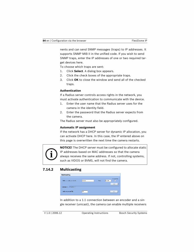
84 en | Configuration via the browser FlexiDome IP
V 1.0 | 2006.12 Operating Instructions Bosch Security Systems
nents and can send SNMP messages (traps) to IP addresses. It supports SNMP MIB II in the unified code. If you wish to send SNMP traps, enter the IP addresses of one or two required tar-get devices here.To choose which traps are sent:1. Click Select. A dialog box appears. 2. Click the check boxes of the appropriate traps. 3. Click OK to close the window and send all of the checked
traps.
AuthenticationIf a Radius server controls access rights in the network, you must activate authentication to communicate with the device. 1. Enter the user name that the Radius server uses for the
camera in the identity field.2. Enter the password that the Radius server expects from
the camera.The Radius server must also be appropriately configured.
Automatic IP assignmentIf the network has a DHCP server for dynamic IP allocation, you can activate DHCP here. In this case, the IP entered above on this page is overwritten the next time the camera restarts.
7.14.2 Multicasting
In addition to a 1:1 connection between an encoder and a sin-gle receiver (unicast), the camera can enable multiple receivers
iNOTICE! The DHCP server must be configured to allocate static IP addresses based on MAC addresses so that the camera always receives the same address. If not, controlling systems, such as VIDOS or BVMS, will not find the camera.
FlexiDome IP Configuration via the browser | en 85
Bosch Security Systems Operating Instructions V 1.0 | 2006.12
to receive the video signal from an encoder simultaneously. This is either done by duplicating the data stream in the unit and then distributing it to multiple receivers (multi-unicast) or by distributing an individual data stream in the network itself to multiple receivers in a defined group (multicast). You can enter a dedicated multicast address and port for each stream. You can switch between the streams by clicking the associated tabs.
A special IP address (class D address) must be configured for multicast operation in a multicast-enabled network. The net-work must support group IP addresses and the Internet Group Management Protocol (IGMP V2). The address range is from 225.0.0.0 to 239.255.255.255. The multicast address can be the same for multiple streams. However, it is then necessary to use a different port in each case so that multiple data streams are not sent simultaneously using the same port and multicast address.
Multicast address video 1Enter a valid multicast address for each stream to be operated in multicast mode (duplication of the data streams in the net-work). With the setting 0.0.0.0 the encoder for the relevant stream operates in multi-unicast mode (copying of data streams in unit). The camera supports multi-unicast connections for up to five simultaneously connected receivers.
iNOTICE! The prerequisite for multicast operation is a multicast-capable network that uses the UDP and IGMP protocols. Other group membership protocols are not supported. The TCP protocol does not support multicast connections.
iNOTICE! Duplication of data places a heavy demand on the CPU and can lead to impairment of the image quality under certain circumstances.
86 en | Configuration via the browser FlexiDome IP
V 1.0 | 2006.12 Operating Instructions Bosch Security Systems
PortIf there are simultaneous data streams at the same multicast address, you must assign different ports to each data stream. Enter the port address for the relevant stream here.
StreamingClick in the checkbox to activate multicast streaming mode for the relevant stream. An activated stream is marked with a check.
Multicast packet TTLA value can be entered to specify how long the multicast data packets are active on the network. If multicast is to be run via a router the value must be greater than 1.
7.14.3 EncryptionYou can activate the encryption of media data (video, audio, metadata) here. Activation also causes RCP+ connections to be encrypted. To encrypt data streams, you should only allow browser connections via SSL. To do this, you must deactivate all ports and protocols except HTTPS (see “HTTPS browser port” on page 82).
You can select individual data streams for encryption. When a key is generated for a stream, data is encrypted. If you delete the key, data is unencrypted for that stream. 1. Select On in the encryption list box to activate encryption.
Activation generates keys for all streams.2. Click Keys >> to display a list of data streams and associ-
ated keys.3. Click an entry to select it (select multiple entries by hold-
ing the control key while clicking).4. Click Clear keys to delete the keys for the marked streams.
These streams are no longer encrypted.
iNOTICE! Encrypting video data requires a lot of computing power.
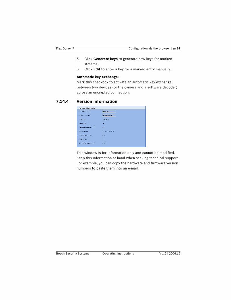
FlexiDome IP Configuration via the browser | en 87
Bosch Security Systems Operating Instructions V 1.0 | 2006.12
5. Click Generate keys to generate new keys for marked streams.
6. Click Edit to enter a key for a marked entry manually.
Automatic key exchange:Mark this checkbox to activate an automatic key exchange between two devices (or the camera and a software decoder) across an encrypted connection.
7.14.4 Version information
This window is for information only and cannot be modified. Keep this information at hand when seeking technical support.For example, you can copy the hardware and firmware version numbers to paste them into an e-mail.
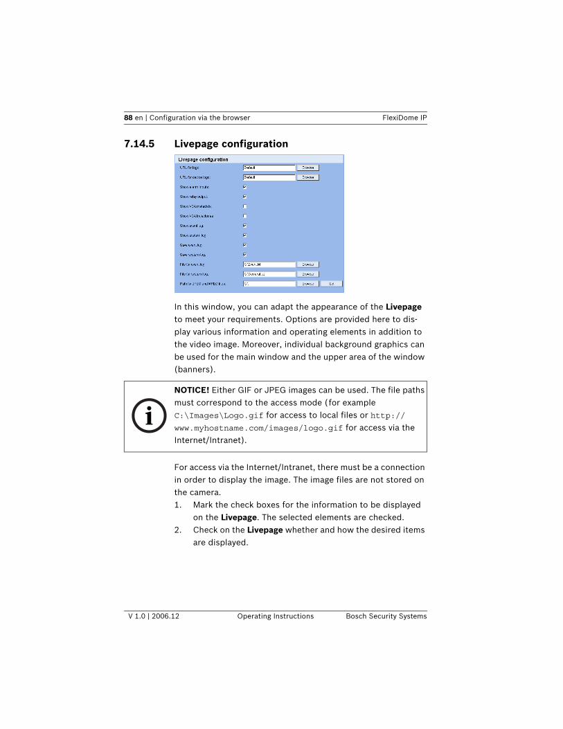
88 en | Configuration via the browser FlexiDome IP
V 1.0 | 2006.12 Operating Instructions Bosch Security Systems
7.14.5 Livepage configuration
In this window, you can adapt the appearance of the Livepage to meet your requirements. Options are provided here to dis-play various information and operating elements in addition to the video image. Moreover, individual background graphics can be used for the main window and the upper area of the window (banners).
For access via the Internet/Intranet, there must be a connection in order to display the image. The image files are not stored on the camera. 1. Mark the check boxes for the information to be displayed
on the Livepage. The selected elements are checked.2. Check on the Livepage whether and how the desired items
are displayed.
iNOTICE! Either GIF or JPEG images can be used. The file paths must correspond to the access mode (for example C:\Images\Logo.gif for access to local files or http://www.myhostname.com/images/logo.gif for access via the Internet/Intranet).
FlexiDome IP Configuration via the browser | en 89
Bosch Security Systems Operating Instructions V 1.0 | 2006.12
Logo URLEnter the path to a suitable background graphic in this field. The image can be stored on a local computer, a local network or at an Internet address.– Click Search if necessary to find a suitable image on the
local network.
Device logo URLEnter the path for a suitable image for the upper part of the window (banner) here. The image can be stored on a local com-puter, a local network or at an Internet address.– Click Search if necessary to find a suitable image on the
local network.
Show alarm inputAlarm inputs are displayed next to the video image as icons along with their assigned names. If an alarm is active the corre-sponding icon changes color.
Show VCA metadataWhen video content analysis (VCA) is activated, additional infor-mation is displayed in the live video stream. For example, in Motion+ mode, the sensor areas for motion detection are marked.
Show VCA trajectories (IVMD 2.0 only)When the IVMD 2.0 algorithm is activated, object trajectories from VCA are displayed in the live video stream.
Show event logThe event messages are displayed with the date and time in a field next to the video image.
iNOTICE! To restore the original graphics, simply delete the entries in the Logo URL and Device logo URL fields.
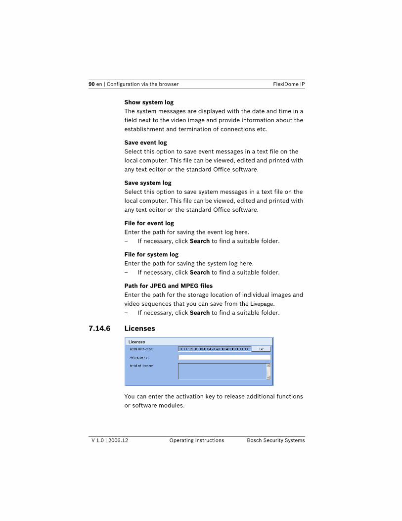
90 en | Configuration via the browser FlexiDome IP
V 1.0 | 2006.12 Operating Instructions Bosch Security Systems
Show system logThe system messages are displayed with the date and time in a field next to the video image and provide information about the establishment and termination of connections etc.
Save event logSelect this option to save event messages in a text file on the local computer. This file can be viewed, edited and printed with any text editor or the standard Office software.
Save system logSelect this option to save system messages in a text file on the local computer. This file can be viewed, edited and printed with any text editor or the standard Office software.
File for event logEnter the path for saving the event log here.– If necessary, click Search to find a suitable folder.
File for system logEnter the path for saving the system log here.– If necessary, click Search to find a suitable folder.
Path for JPEG and MPEG filesEnter the path for the storage location of individual images and video sequences that you can save from the Livepage.– If necessary, click Search to find a suitable folder.
7.14.6 Licenses
You can enter the activation key to release additional functions or software modules.
FlexiDome IP Configuration via the browser | en 91
Bosch Security Systems Operating Instructions V 1.0 | 2006.12
7.14.7 Maintenance
Firmware updateThe camera functions and parameters can be updated with firmware. To do this, the current firmware package is trans-ferred to the unit via the network. The firmware is installed there automatically. Thus a camera can be serviced and updated remotely without requiring a technician to make changes to the unit on site. The latest firmware can be obtained from your customer service center or from the Bosch Security Systems download area.
iNOTICE! The activation key cannot be deactivated again and is not transferable to other units.
!CAUTION! Before starting the firmware update, make sure that you have selected the correct upload file! Uploading the wrong files can result in the unit no longer being addressable, requiring it to be replaced.
!CAUTION! Do not interrupt the firmware installation for any reason! Interruption may lead to faulty coding of the Flash EPROM. This can result in the unit no longer being addressable, requiring it to be replaced.
92 en | Configuration via the browser FlexiDome IP
V 1.0 | 2006.12 Operating Instructions Bosch Security Systems
To update the firmware:1. First, save the update file to the hard disk.2. Enter the full path for the update file in the field or click
Browse... to locate and select the file.3. Click Upload to begin transmission to the unit. The
progress bar allows you to monitor the transfer.
The new firmware is unpacked and the Flash EPROM is repro-grammed. The time remaining is shown by the message going to reset Reconnecting in ... seconds. After the upload is com-pleted successfully, the unit restarts automatically.If the operating status LED lights up red, the upload has failed and must be repeated. To perform the upload, you must switch to a special page:1. In the address bar of your browser, after the unit IP
address enter/main.htm (for example 192.168.0.80/main.htm).
2. Repeat the upload.
Configuration downloadYou can save configuration data for the camera to a computer and load saved configuration data from a computer to the unit.1. Click Download; a dialog box appears.2. Follow the instructions to save the current settings.
iNOTICE! A firmware update resets all camera parameters to their factory default values. If you wish to retain the old values first save the configuration by performing a configuration download. After the firmware update you can reload your parameter values by performing a configuration upload.
iNOTICE! Installing new firmware and reconfiguring the camera takes several minutes.
FlexiDome IP Configuration via the browser | en 93
Bosch Security Systems Operating Instructions V 1.0 | 2006.12
Configuration upload1. Enter the full path of the file to upload or click Browse... to
select the desired file.2. Make certain that the file to be loaded comes from the
same device type as the unit you want to reconfigure.3. Click Upload to begin transmission to the unit. The
progress bar allows you to monitor the transfer.Once the upload is complete, the new configuration is acti-vated. The time remaining is shown by the message going to reset Reconnecting in ... seconds. After the upload is com-pleted successfully, the unit restarts automatically.
SSL certificate upload To work with an SSL connection, both sides of the connection must have the appropriate certificates. You can upload one or more certificate files, one at a time, to the camera. 1. Enter the full path of the file you wish to upload or click
Browse... to locate the file.2. Click Upload to start the file transfer. The unit restarts automatically after a successful upload.
7.15 Function testThe camera offers a variety of configuration options. Therefore you should check that it works properly after installation and configuration. This is the only way to ensure that the camera will function as intended in the event of an alarm. Your check should include the following functions:– Can the camera be called remotely?– Does the camera transmit all the data required?– Does the camera respond as desired to alarm events?– Is it possible to control peripheral devices if necessary?
94 en | Connections between video servers FlexiDome IP
V 1.0 | 2006.12 Operating Instructions Bosch Security Systems
8 Connections between video serversA camera can be used as a transmitter and a compatible MPEG4 hardware decoder with a connected monitor as a receiver using an Ethernet network connection. This way it is possible to cover large distances with little effort for installation or cabling.
8.0.1 InstallationCameras are designed to connect with other VIP devices auto-matically with the corresponding configuration. This only requires that they are part of a closed network. Proceed as fol-lows to install the devices:1. Connect the devices to the closed network using Ethernet
cables.2. Connect them to the power supply.
8.0.2 Establishing the connectionThere are three options for establishing a connection between a transmitter and a compatible receiver in a closed network: – an alarm,– a Web browser– via the configuration manager
8.0.3 Connect on alarmWith the appropriate configuration, a connection between a transmitter and a receiver is established automatically when an alarm is triggered. After a short time, the live video image from the transmitter is shown on the connected monitor.This connection option can also be used to connect a transmit-ter and a compatible receiver using a switch connected to the alarm input. In this case, no computer is needed to establish the connection.
iNOTICE! Make sure the devices are configured for the network environment and the correct IP address for the remote location to be contacted in the event of an alarm is set on the Alarm connections configuration page.
FlexiDome IP Connections between video servers | en 95
Bosch Security Systems Operating Instructions V 1.0 | 2006.12
8.0.4 Connecting with a Web browserVarious requirements must be met in order to operate using a Web program.
1. Use the Web browser to connect to the receiver. Its home page is displayed.
Under Video sources on the page Connections, select the cam-era. A JPEG snapshot of the selected video source is displayed on the page.2. Click an MPEG-4 connection to begin displaying the video
images on the connected monitor.
8.0.5 Closing the connectionThe connection may be closed using a Web browser.1. Use the Web browser to connect to the receiver. Its home
page is displayed.2. In the title bar of the Monitor window on the page Connec-
tions, click on the X icon to end the display of the video images on the connected monitor.
iNOTICE! Transmitter and receiver must be located in the same subnet to establish a hardware connection with a Web browser.
96 en | Operation with decoder software FlexiDome IP
V 1.0 | 2006.12 Operating Instructions Bosch Security Systems
9 Operation with decoder softwareVIDOSThe camera video server and VIDOS software combine to pro-vide a high-performance system solution. VIDOS is software for operating, controlling and administering CCTV installations (such as surveillance systems) at remote locations. It runs under Microsoft Windows operating systems. Its main job is decoding video, audio and control data from a remote transmit-ter. There are many options available for operation and configu-ration when using a camera with VIDOS.
BVMSThe Bosch Video Management System (BVMS) is a unique enterprise IP video security solution that provides seamless management of digital video, audio and data across any IP net-work. It is designed to work with Bosch CCTV products as part of a total video security management system. Now you can inte-grate your existing components into one easy-to-manage sys-tem, or use Bosch’s full-line capabilities and benefit from a complete security solution based on cutting-edge technology and years of experience.
DiBos 8The camera is also designed for use with DiBos 8 Video Record-ers. DiBos 8 can record up to 32 video and audio streams, and is available as software or a a hybrid DVR with additional analog camera and audio inputs. DiBos supports various functions of the camera, such as controlling relays, remote control of peripheral devices and remote configuration. DiBos 8 can use alarm inputs to trigger actions and, when motion detection Motion+ is active, can record the relevant cells, making intelli-gent motion detection possible.
FlexiDome IP Maintenance | en 97
Bosch Security Systems Operating Instructions V 1.0 | 2006.12
10 Maintenance
10.1 Testing the network connectionThe ping command can be used to check the connection between two IP addresses. This allows you to test whether a device is active in the network. 1. Open the DOS command prompt.2. Type ping followed by the IP address of the device.If the device is found, the response appears as " Reply from ... ", followed by the number of bytes sent and the transmis-sion time in milliseconds. Otherwise, the device cannot be accessed via the network. This might be because: – The device is not properly connected to the network.
Check the cable connections in this case. – The device is not correctly integrated into the network.
Check the IP address, subnet mask and gateway address.
10.2 Repairs
10.2.1 Transfer and disposalThe camera should only be passed on together with this instal-lation guide. The unit contains environmentally hazardous mate-rials that must be disposed of according to law. Defective or superfluous devices and parts should be disposed of profes-sionally or taken to your local collection point for hazardous materials.
!
CAUTION! Never open the casing of the camera. The unit does not contain any user serviceable parts. Ensure that all maintenance or repair work is performed only by qualified personnel (electrical engineering or network technology specialists). In case of doubt, contact your dealer's technical service center.
98 en | Troubleshooting FlexiDome IP
V 1.0 | 2006.12 Operating Instructions Bosch Security Systems
11 TroubleshootingIf you cannot resolve a fault, please contact your supplier or system integrator or go direct to Bosch Security Systems Cus-tomer Service.The version numbers of the internal processors can be viewed on a special page. Please note this information before contact-ing Customer Service.1. In the address bar of your browser, after the unit IP
address enter/version (for example 192.168.0.80/version).
2. Write down the information or print out the page.The following table is intended to help you identify the causes of malfunctions and correct them where possible.
Malfunction Possible causes Solution
No image transmis-
sion to remote loca-
tion.
Defective camera. Connect a local monitor to the
camera and check the camera
function.
Faulty cable connections. Check all cables, plugs, contacts
and connections.
No connection estab-
lished, no image
transmission.
The unit's configuration. Check all configuration parame-
ters.
Faulty installation. Check all cables, plugs, contacts
and connections.
Wrong IP address. Check the IP addresses (terminal
program).
Faulty data transmission
within the LAN.
Check the data transmission with
ping.
The maximum number of
connections has been
reached.
Wait until there is a free connec-
tion and call the transmitter again.
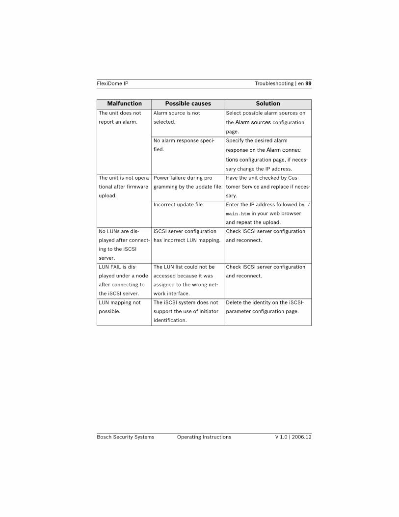
FlexiDome IP Troubleshooting | en 99
Bosch Security Systems Operating Instructions V 1.0 | 2006.12
The unit does not
report an alarm.
Alarm source is not
selected.
Select possible alarm sources on
the Alarm sources configuration
page.
No alarm response speci-
fied.
Specify the desired alarm
response on the Alarm connec-
tions configuration page, if neces-
sary change the IP address.
The unit is not opera-
tional after firmware
upload.
Power failure during pro-
gramming by the update file.
Have the unit checked by Cus-
tomer Service and replace if neces-
sary.
Incorrect update file. Enter the IP address followed by /
main.htm in your web browser
and repeat the upload.
No LUNs are dis-
played after connect-
ing to the iSCSI
server.
iSCSI server configuration
has incorrect LUN mapping.
Check iSCSI server configuration
and reconnect.
LUN FAIL is dis-
played under a node
after connecting to
the iSCSI server.
The LUN list could not be
accessed because it was
assigned to the wrong net-
work interface.
Check iSCSI server configuration
and reconnect.
LUN mapping not
possible.
The iSCSI system does not
support the use of initiator
identification.
Delete the identity on the iSCSI-
parameter configuration page.
Malfunction Possible causes Solution
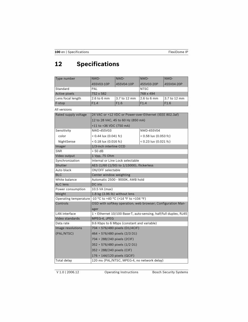
100 en | Specifications FlexiDome IP
V 1.0 | 2006.12 Operating Instructions Bosch Security Systems
12 Specifications
Type number NWD-
455V03-10P
NWD-
455V04-10P
NWD-
455V03-20P
NWD-
455V04-20PStandard PAL NTSCActive pixels 752 x 582 768 x 494Lens focal length 2.6 to 6 mm 3.7 to 12 mm 2.6 to 6 mm 3.7 to 12 mmF-stop F1.4 F1.6 F1.4 F1.6
All versions
Rated supply voltage 24 VAC or +12 VDC or Power-over-Ethernet (IEEE 802.3af)
12 to 28 VAC, 45 to 60 Hz (850 mA)
+11 to +36 VDC (750 mA)Sensitivity
color
NightSense
NWD-455V03
< 0.44 lux (0.041 fc)
< 0.18 lux (0.016 fc)
NWD-455V04
< 0.58 lux (0.053 fc)
< 0.23 lux (0.021 fc)Imager 1/3-inch interline CCDSNR > 50 dBVideo output 1 Vpp, 75 OhmSynchronization Internal or Line Lock selectableShutter AES (1/60 (1/50) to 1/15000), flickerless Auto black ON/OFF selectableBLC Center window weightingWhite balance Automatic 2500 - 9000K, AWB holdALC lens DC iris Power consumption 10.5 VA (max)Weight 1.8 kg (3.96 lb) without lensOperating temperature -10 °C to +40 °C (+14 °F to +104 °F)Controls OSD with softkey operation; web browser; Configuration Man-
agerLAN interface 1 × Ethernet 10/100 Base-T, auto-sensing, half/full duplex, RJ45Video standards MPEG-4, JPEGData rate 9.6 Kbps to 6 Mbps (constant and variable)Image resolutions
(PAL/NTSC)
704 × 576/480 pixels (D1/4CIF)
464 × 576/480 pixels (2/3 D1)
704 × 288/240 pixels (2CIF)
352 × 576/480 pixels (1/2 D1)
352 × 288/240 pixels (CIF)
176 × 144/120 pixels (QCIF)Total delay 120 ms (PAL/NTSC, MPEG-4, no network delay)
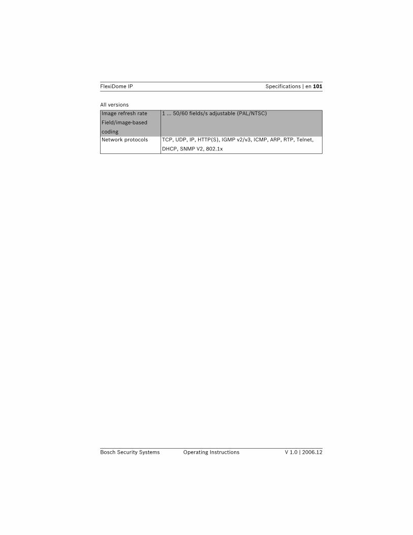
FlexiDome IP Specifications | en 101
Bosch Security Systems Operating Instructions V 1.0 | 2006.12
Image refresh rate
Field/image-based
coding
1 ... 50/60 fields/s adjustable (PAL/NTSC)
Network protocols TCP, UDP, IP, HTTP(S), IGMP v2/v3, ICMP, ARP, RTP, Telnet,
DHCP, SNMP V2, 802.1x
All versions
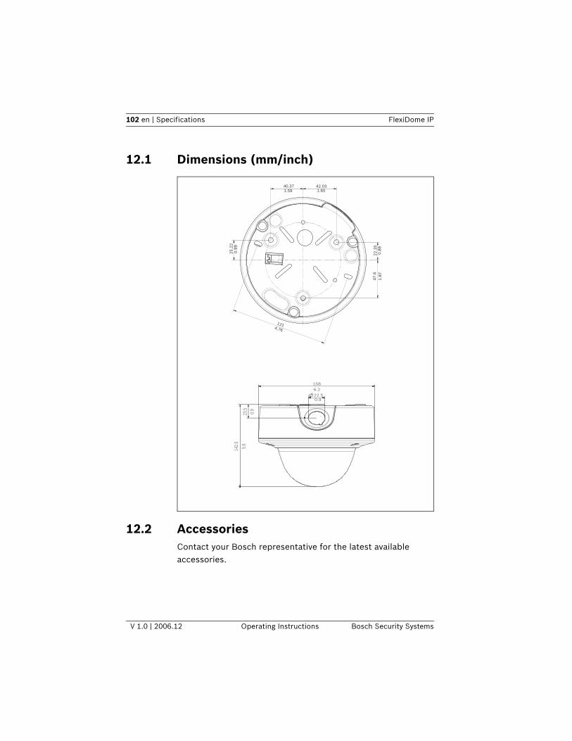
102 en | Specifications FlexiDome IP
V 1.0 | 2006.12 Operating Instructions Bosch Security Systems
12.1 Dimensions (mm/inch)
12.2 AccessoriesContact your Bosch representative for the latest available accessories.
40.37 42.031.651.59
22
.35
1.8
70
.88
47
.6
0.9
92
5.2
2
4.76
121
158
6.2
22.50.9
23.5
5.6
0.9
142.
5
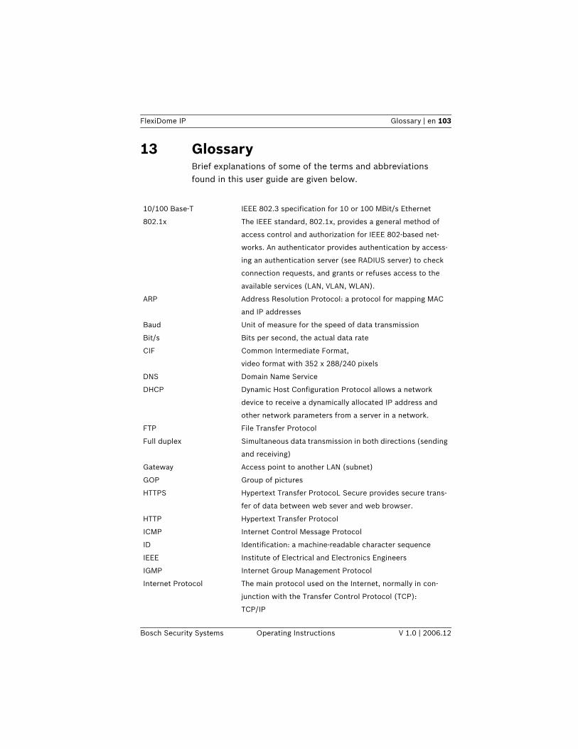
FlexiDome IP Glossary | en 103
Bosch Security Systems Operating Instructions V 1.0 | 2006.12
13 GlossaryBrief explanations of some of the terms and abbreviations found in this user guide are given below.
10/100 Base-T IEEE 802.3 specification for 10 or 100 MBit/s Ethernet
802.1x The IEEE standard, 802.1x, provides a general method of
access control and authorization for IEEE 802-based net-
works. An authenticator provides authentication by access-
ing an authentication server (see RADIUS server) to check
connection requests, and grants or refuses access to the
available services (LAN, VLAN, WLAN).
ARP Address Resolution Protocol: a protocol for mapping MAC
and IP addresses
Baud Unit of measure for the speed of data transmission
Bit/s Bits per second, the actual data rate
CIF Common Intermediate Format,
video format with 352 x 288/240 pixels
DNS Domain Name Service
DHCP Dynamic Host Configuration Protocol allows a network
device to receive a dynamically allocated IP address and
other network parameters from a server in a network.
FTP File Transfer Protocol
Full duplex Simultaneous data transmission in both directions (sending
and receiving)
Gateway Access point to another LAN (subnet)
GOP Group of pictures
HTTPS Hypertext Transfer ProtocoL Secure provides secure trans-
fer of data between web sever and web browser.
HTTP Hypertext Transfer Protocol
ICMP Internet Control Message Protocol
ID Identification: a machine-readable character sequence
IEEE Institute of Electrical and Electronics Engineers
IGMP Internet Group Management Protocol
Internet Protocol The main protocol used on the Internet, normally in con-
junction with the Transfer Control Protocol (TCP):
TCP/IP
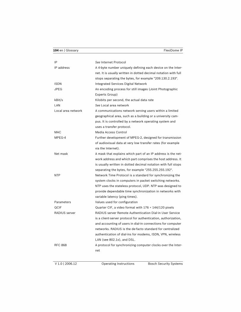
104 en | Glossary FlexiDome IP
V 1.0 | 2006.12 Operating Instructions Bosch Security Systems
IP See Internet Protocol
IP address A 4-byte number uniquely defining each device on the Inter-
net. It is usually written in dotted decimal notation with full
stops separating the bytes, for example "209.130.2.193".
ISDN Integrated Services Digital Network
JPEG An encoding process for still images (Joint Photographic
Experts Group)
kBit/s Kilobits per second, the actual data rate
LAN See Local area network
Local area network A communications network serving users within a limited
geographical area, such as a building or a university cam-
pus. It is controlled by a network operating system and
uses a transfer protocol.
MAC Media Access Control
MPEG-4 Further development of MPEG-2, designed for transmission
of audiovisual data at very low transfer rates (for example
via the Internet).
Net mask A mask that explains which part of an IP address is the net-
work address and which part comprises the host address. It
is usually written in dotted decimal notation with full stops
separating the bytes, for example "255.255.255.192".
NTP Network Time Protocol is a standard for synchronizing the
system clocks in computers in packet switching networks.
NTP uses the stateless protocol, UDP. NTP was designed to
provide dependable time synchronization in networks with
variable latency (ping times).
Parameters Values used for configuration
QCIF Quarter CIF, a video format with 176 × 144/120 pixels
RADIUS server RADIUS server Remote Authentication Dial-in User Service
is a client-server protocol for authentication, authorization,
and accounting of users in dial-in connections for computer
networks. RADIUS is the de-facto standard for centralized
authentication of dial-ins for modems, ISDN, VPN, wireless
LAN (see 802.1x), and DSL.
RFC 868 A protocol for synchronizing computer clocks over the Inter-
net
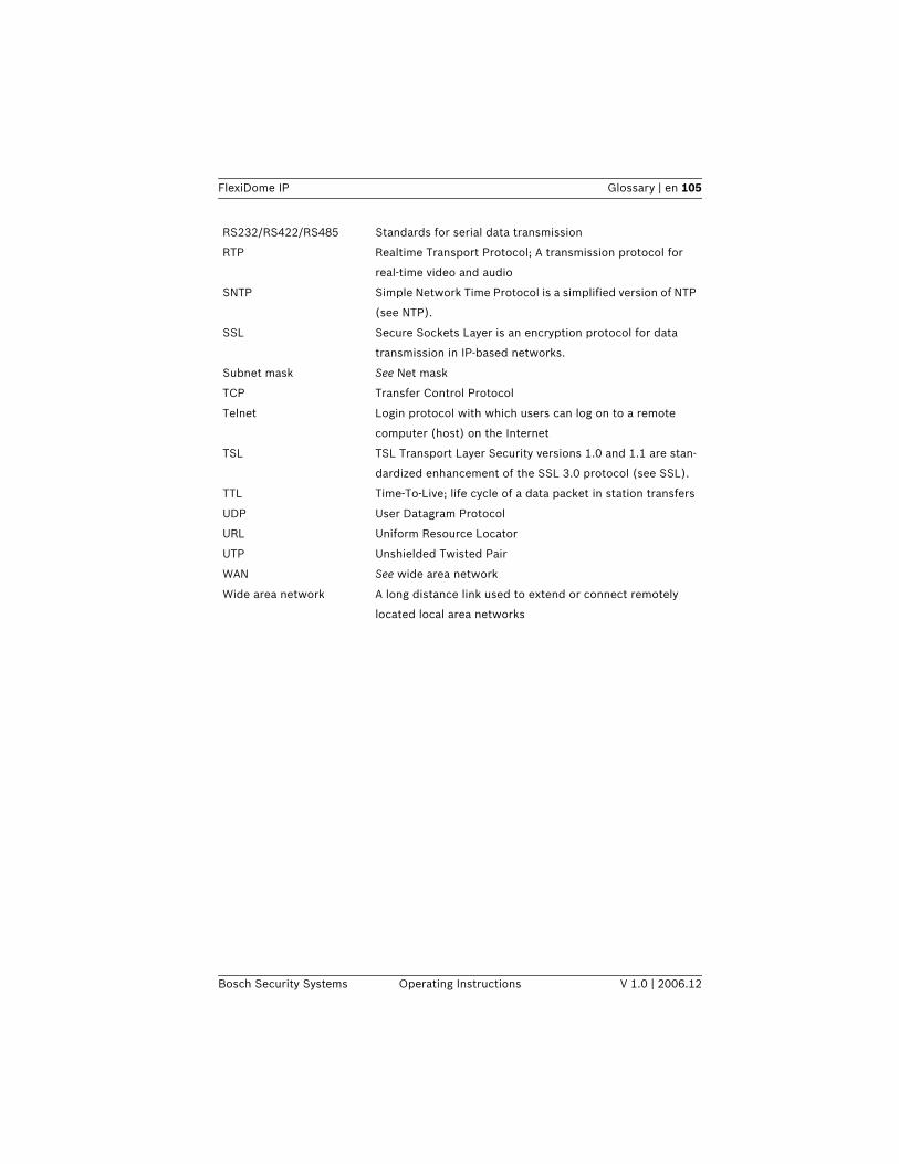
FlexiDome IP Glossary | en 105
Bosch Security Systems Operating Instructions V 1.0 | 2006.12
RS232/RS422/RS485 Standards for serial data transmission
RTP Realtime Transport Protocol; A transmission protocol for
real-time video and audio
SNTP Simple Network Time Protocol is a simplified version of NTP
(see NTP).
SSL Secure Sockets Layer is an encryption protocol for data
transmission in IP-based networks.
Subnet mask See Net mask
TCP Transfer Control Protocol
Telnet Login protocol with which users can log on to a remote
computer (host) on the Internet
TSL TSL Transport Layer Security versions 1.0 and 1.1 are stan-
dardized enhancement of the SSL 3.0 protocol (see SSL).
TTL Time-To-Live; life cycle of a data packet in station transfers
UDP User Datagram Protocol
URL Uniform Resource Locator
UTP Unshielded Twisted Pair
WAN See wide area network
Wide area network A long distance link used to extend or connect remotely
located local area networks
Bosch Security Systems Robert-Koch-Straße 100D-85521 OttobrunnGermanywww.boschsecuritysystems.com © Bosch Security Systems, 2007