Embed Size (px)
Citation preview
����������������
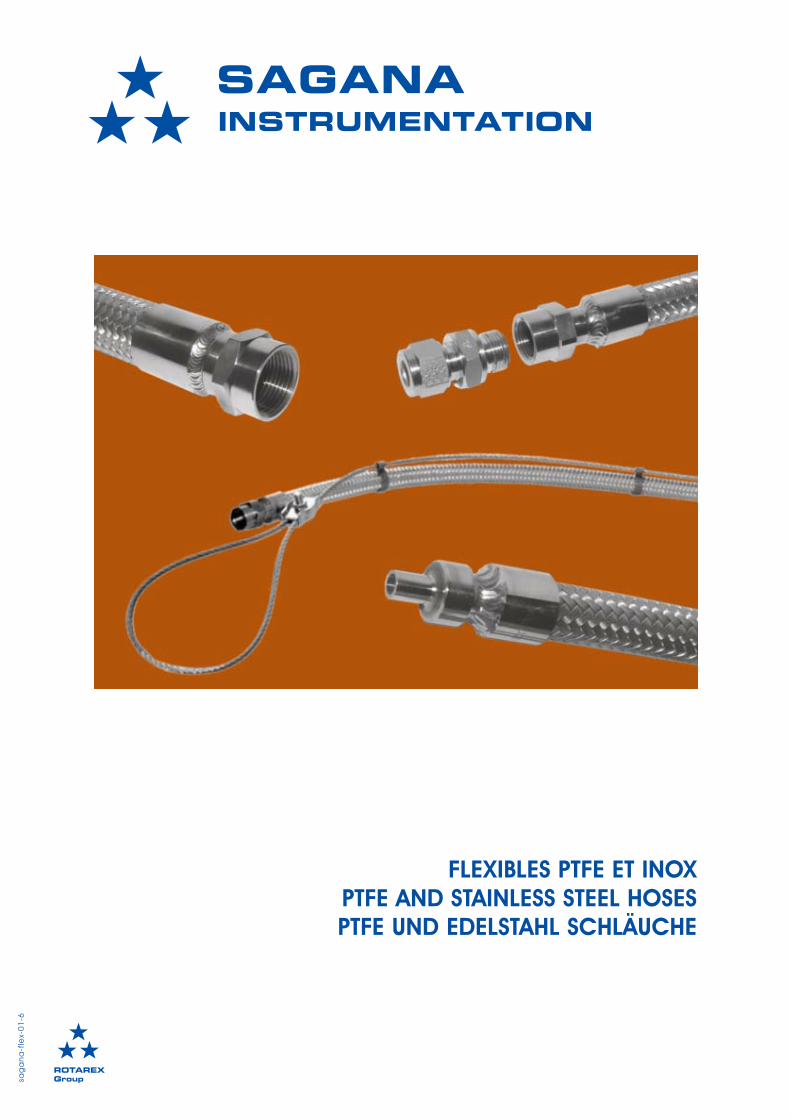
FLEXIBLES PTFE ET INOXPTFE AND STAINLESS STEEL HOSESPTFE UND EDELSTAHL SCHLÄUCHE
���� �����sa
ga
na
-fle
x-0
1-6

sagana-flex-cat-01-6
����������������
Droits de modifications réservés All rights of change reserved Änderungsrechte vorbehalten 3
SOMMAIRE TABLE OF CONTENTS INHALTSVERZEICHNIS
Description
Applications
Description des flexibles FX01
Description des flexibles FX02
Spécifications des flexibles FX01et FX02 - Pression de service - Température - Mouvements et vibrations - Rayon de courbure - option cable de sécurité
Codifications - Composer une référence - Raccordements standards
Descriptions des raccordements
Longueur utile
Descriptions des flexibles pourcadres et centrales
Codification des flexibles pourcadres et centales
Mise en situation
Informations techniques
Description
Applications
Description of FX01 hoses
Description of FX02 hoses
Specifications of FX01 and FX02hoses - Operating pressure - Temperature - Motion and vibrations - Bending radius - optional safety cable
Ordering Information- Selecting a reference- Standard connections
Connection description
Effective length
Description of hoses for racksand switch over boards
Ordering Information of hosesfor racks and switch over boards
Installation
Technical data
Beschreibung
Anwendungen
Beschreibung de FX01 Schläuche
Beschreibung der FX02 Schläuche
Allgemeine Spezifikationen deFX01 und FX02 Schläuche - Betriebsdruck - Temperatur - Bewegung und Vibrationen - Biegeradius - optionales Sicherheitskabel
Kodierung- Aufbau einer Referenz- Standardanschlüsse
Beschreibung der Anschlüsse
Effektive Länge
Beschreibung der Schläuche fürBündel und Inversionsanlagen
Kodierung der Schläuche fürBündel und Inversionsanlagen
Einsatz
Technische Daten
4
5
6
7
8
10
12
14
15
16
17
18
4
5
6
7
8
10
12
14
15
16
17
18
4
5
6
7
8
10
12
14
15
16
17
18
4sagana-flex-cat-01-6
����������������
Droits de modifications réservés All rights of change reserved Änderungsrechte vorbehalten
DESCRIPTION DESCRIPTION BESCHREIBUNG
Les flexibles SAGANA® garantissentune très grande sécuritéd’utilisation.Ils sont conçus ethomologués selon les dernièresnormes en vigueur. Les flexiblesSAGANA® permettent leraccordement de tuyauteries oud’installations dans des conditionscritiques de pression et / ou detempérature. Ils sont conçus pourêtre le plus universel notammentpar l’adjonction d’adaptateurs. Ilexiste 2 familles de flexiblessuivant leur composition et leurutilisation.
Les flexibles désignés sous le sigleFX01 sont composés d’un tubeintérieur en PTFE et d’une tressesimple ou double en inox.
Les flexibles désignés sous le sigleFX02 sont composés d’un tubeintérieur en Inox 316L et d’unetresse simple ou double en inox.
Les flexibles SAGANA® permettentun grand nombre d’utilisations parl’adjonction des différents typesde raccords de la gammeSAGANA® Instrumentation.
Nous recommandons un cablede sécurité à partir d’unelongueur de 1 mètre.Le cable de sécurité est proposéen option.
Tous les flexibles sont testésindividuellement en étanchéité ethydrauliquement à 1,5 fois lapression de service maximale.
SAGANA® hoses guarantee thehighest degree of safety. Theyare designed and certified inaccordance with the lateststandards in effect. SAGANA®
hoses allow connection of pipingsystems and equipment undersome of the most severe pressureand/or temperature conditions.They can be easily installedthrough the use of adapters.There are two types of hosesbased upon their compositionand use.
FX01 hoses consist of a PTFE innertube and a stainless steel single ordouble braid.
FX02 hoses consist of a 316Lstainless steel inner tube and astainless steel single or doublebraid.
SAGANA® hoses have a widerange of uses through theaddition of various types ofadapters of the SAGANA®
instrumentation line of products.
We recommend a safety cable ofat least 1 meter. The safety cableis optional.
All hoses are individually testedhydraulically at 1.5 times themaximum working pressure.
SAGANA® Schläuche garantierenein Höchstmass anAnwendungssicherheit. Sie wurdenentwickelt und gefertigt nach denletzten Standards. SAGANA®
Schläuche erlauben dieVerbindung von Anlagen undInstallationen unter härtestenDruck und TemperaturBedingungen. Sie wurdenentwickelt um besondersuniversell anwendbar zu sein,durch die Verwendung vonAdaptern. Es gibt zwei Versionenvon Schläuchen nach Materialiengeordnet: PTFE-Edelstahl, undEdelstahl.
FX01 Schläuche bestehen auseinem Innenschlauch aus PTFEund einer einfachen oderdoppelten Umflechtung ausEdelstahl.
FX02 Schläuche bestehen auseinem Edelstahl-Innenschlauch316L und einer einfachen oderdoppelten Umflechtung ausEdelstahl.
SAGANA® Schläuche sind vielseitigeinsetzbar durch den Zusatzverschiedener Verbindungsteileder Produktreihe SAGANA®
Instrumentation.
Wir empfehlen einSicherheitskabel ab einer Längevon 1 Meter.Das Sicherheitskabelist als Option erhältlich.
Alle Schläuche werden einzeln aufDichtigkeit und hydraulisch mit 1,5fachem Betriebsdruck getestet.
sagana-flex-cat-01-6
����������������
Droits de modifications réservés All rights of change reserved Änderungsrechte vorbehalten 5
Les flexibles SAGANA® ont étéconçus pour apporter à leursutilisateurs efficacité, sécurité etfacilité de mise en oeuvre. Lesflexibles SAGANA® sont utilisablessur produits liquides, gazeux ou enultra-vide dans des industries tellesque :- chimie- pétrochimie- industrie des gaz- énergie- papeterie- centres de recherche- applications du vide- systèmes hydrauliques- systèmes pneumatiques- laboratoires- etc ...
SAGANA® hoses were designed forefficiency, security andconvenience. SAGANA® hoses areused for liquid and gas service orunder ultra-vacuum in industriessuch as:- chemical- petrochemical- gas- energy- paper- research centers- vacuum applications- hydraulic systems- pneumatic systems- laboratories,- etc...
SAGANA® Schläuche wurdenentwickelt um dem BenutzerLeistungsfähigkeit, Sicherheit undBequemlichkeit zu geben.SAGANA® Schläuche sindanwendbar für Flüssigkeiten,Gase, oder Vakuum in vielenIndustriezweigen wie:- Chemie- Petrochemie- Gasindustrie- Energie- Papierfabrik- Entwicklungslabors- Unterdruck Anwendungen- Hydraulische Systeme- Pneumatische Systeme- Labore- uvm...
APPLICATIONS APPLICATIONS ANWENDUNGEN
6sagana-flex-11-4
Droits de modifications réservés All rights of change reserved Änderungsrechte vorbehalten
����������������
DESCRIPTION DESCRIPTION BESCHREIBUNG
FX01
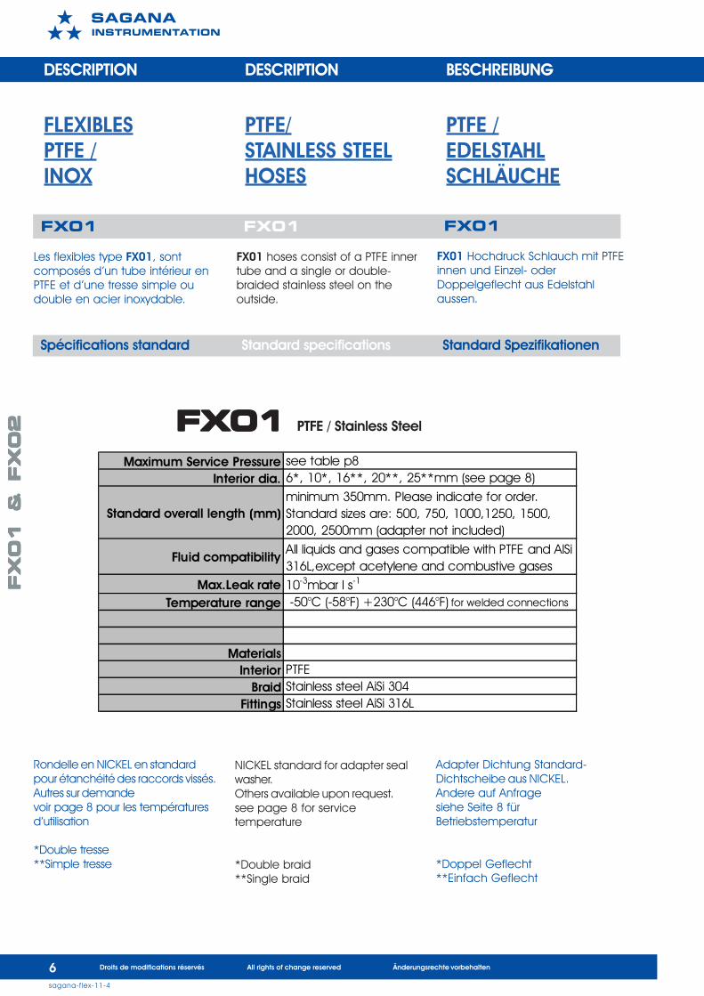
Les flexibles type FX01, sontcomposés d’un tube intérieur enPTFE et d’une tresse simple oudouble en acier inoxydable.
FX01
FX01 hoses consist of a PTFE innertube and a single or double-braided stainless steel on theoutside.
FX01
FX01 Hochdruck Schlauch mit PTFEinnen und Einzel- oderDoppelgeflecht aus Edelstahlaussen.
Maximum Service Pressure see table p8Interior dia. 6*, 10*, 16**, 20**, 25**mm (see page 8)
Standard overall length (mm)minimum 350mm. Please indicate for order. Standard sizes are: 500, 750, 1000,1250, 1500, 2000, 2500mm (adapter not included)
Fluid compatibilityAll liquids and gases compatible with PTFE and AlSi 316L,except acetylene and combustive gases
Max.Leak rate 10-3mbar l s-1
Temperature range -50°C (-58°F) +230°C (446°F) for welded connections
MaterialsInterior PTFE
Braid Stainless steel AiSi 304Fittings Stainless steel AiSi 316L
FLEXIBLES PTFE/ PTFE /PTFE / STAINLESS STEEL EDELSTAHLINOX HOSES SCHLÄUCHE
FX01 FX01 FX01 FX01 FX01 PTFE / Stainless Steel
Spécifications standard Standard specifications Standard Spezifikationen
Rondelle en NICKEL en standardpour étanchéité des raccords vissés.Autres sur demandevoir page 8 pour les températuresd’utilisation
*Double tresse**Simple tresse
NICKEL standard for adapter sealwasher.Others available upon request.see page 8 for servicetemperature
*Double braid**Single braid
Adapter Dichtung Standard-Dichtscheibe aus NICKEL.Andere auf Anfragesiehe Seite 8 fürBetriebstemperatur
*Doppel Geflecht**Einfach Geflecht
FX
01
&
FX
02
FX
01
&
FX
02
FX
01
&
FX
02
FX
01
&
FX
02
FX
01
&
FX
02
7sagana-flex-11-4
Droits de modifications réservés All rights of change reserved Änderungsrechte vorbehalten
����������������
FX02
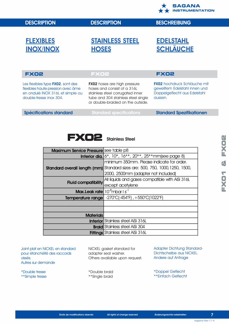
Les flexibles type FX02, sont desflexibles haute pression avec âmeen ondulé INOX 316L et simple oudouble-tresse inox 304.
FX02
FX02 hoses are high pressurehoses and consist of a 316Lstainless steel corrugated innertube and 304 stainless steel singleor double-braided on the outside.
FX02
FX02 hochdruck Schläuche mitgewelltem Edelstahl innen undDoppelgeflecht aus Edelstahlaussen.
Maximum Service Pressure see table p8Interior dia. 6*, 10*, 16**, 20**, 25**mm(see page 8)
Standard overall length (mm)minimum 350mm. Please indicate for order. Standard sizes are: 500, 750, 1000,1250, 1500, 2000, 2500mm (adapter not included)
Fluid compatibilityAll liquids and gases compatible with AiSi 316L except acetylene
Max.Leak rate 10-8mbar l s-1
Temperature range -270°C(-454°F) ,+550°C(1022°F)
MaterialsInterior Stainless steel AiSi 316L
Braid Stainless steel AiSi 304Fittings Stainless steel AiSi 316L
FLEXIBLES STAINLESS STEEL EDELSTAHLINOX/INOX HOSES SCHLÄUCHE
FX02 FX02 FX02 FX02 FX02 Stainless Steel
DESCRIPTION DESCRIPTION BESCHREIBUNG
Spécifications standard Standard specifications Standard Spezifikationen
Joint plat en NICKEL en standardpour étanchéité des raccordsvissés.Autres sur demande
*Double tresse**Simple tresse
NICKEL gasket standard foradapter seal washer.Others available upon request.
*Double braid**Single braid
Adapter Dichtung Standard-Dichtscheibe aus NICKEL.Andere auf Anfrage
*Doppel Geflecht**Einfach Geflecht
FX
01
&
FX
02
FX
01
&
FX
02
FX
01
&
FX
02
FX
01
&
FX
02
FX
01
&
FX
02
8sagana-flex-cat-01-6
����������������
Droits de modifications réservés All rights of change reserved Änderungsrechte vorbehalten
SPECIFICATIONS SPECIFICATIONS SPEZIFIKATIONEN
Pression de service Operating Pressure Betriebsdruck
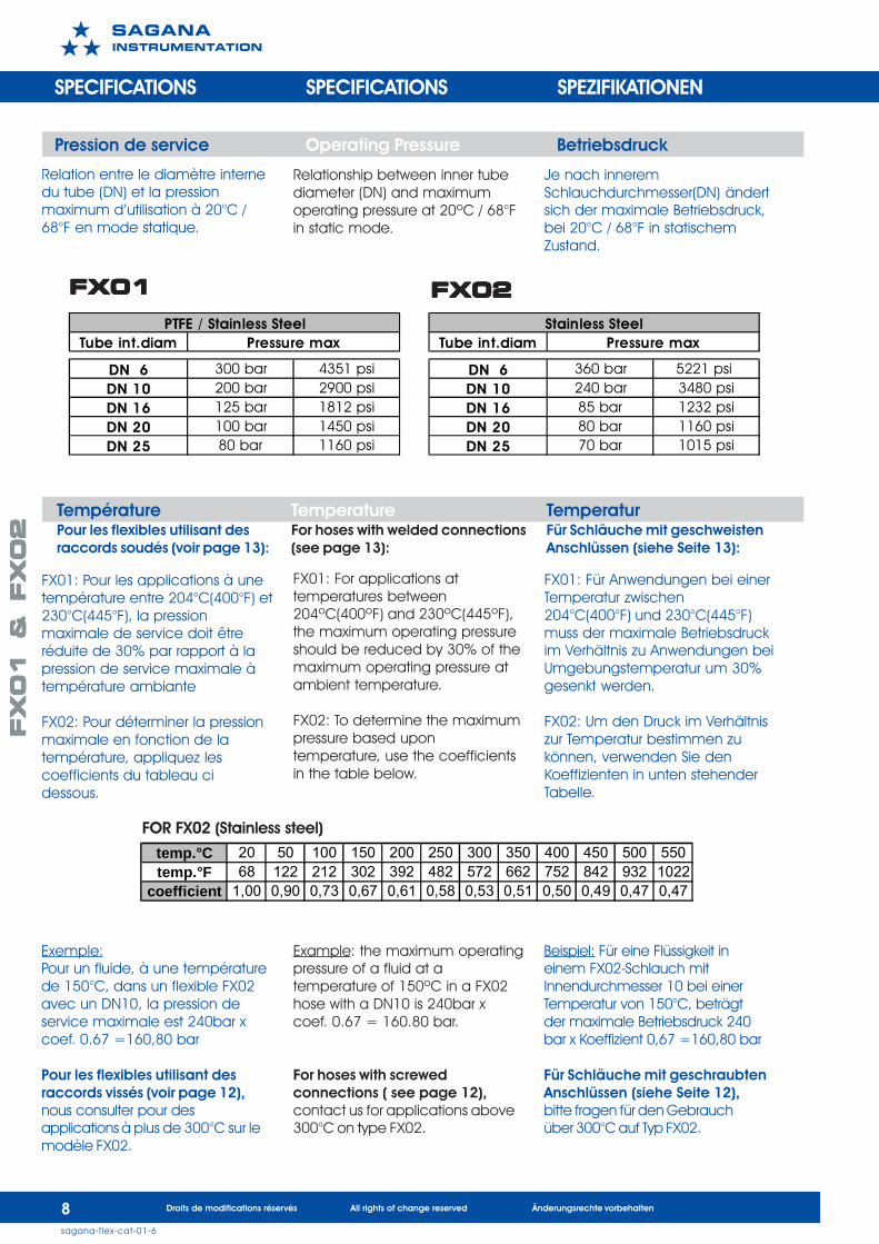
Relationship between inner tubediameter (DN) and maximumoperating pressure at 20ºC / 68°Fin static mode.
Je nach inneremSchlauchdurchmesser(DN) ändertsich der maximale Betriebsdruck,bei 20°C / 68°F in statischemZustand.
Relation entre le diamètre internedu tube (DN) et la pressionmaximum d’utilisation à 20°C /68°F en mode statique.
FX01: For applications attemperatures between204ºC(400ºF) and 230ºC(445ºF),the maximum operating pressureshould be reduced by 30% of themaximum operating pressure atambient temperature.
FX02: To determine the maximumpressure based upontemperature, use the coefficientsin the table below.
Example: the maximum operatingpressure of a fluid at atemperature of 150ºC in a FX02hose with a DN10 is 240bar xcoef. 0.67 = 160.80 bar.
For hoses with screwedconnections ( see page 12),contact us for applications above300°C on type FX02.
FX01: Für Anwendungen bei einerTemperatur zwischen204°C(400°F) und 230°C(445°F)muss der maximale Betriebsdruckim Verhältnis zu Anwendungen beiUmgebungstemperatur um 30%gesenkt werden.
FX02: Um den Druck im Verhältniszur Temperatur bestimmen zukönnen, verwenden Sie denKoeffizienten in unten stehenderTabelle.
FX01: Pour les applications à unetempérature entre 204°C(400°F) et230°C(445°F), la pressionmaximale de service doit êtreréduite de 30% par rapport à lapression de service maximale àtempérature ambiante
FX02: Pour déterminer la pressionmaximale en fonction de latempérature, appliquez lescoefficients du tableau cidessous.
FX01FX01FX01FX01FX01 FX02FX02FX02FX02FX02
Température Temperature TemperaturPour les flexibles utilisant des For hoses with welded connections Für Schläuche mit geschweistenraccords soudés (voir page 13): (see page 13): Anschlüssen (siehe Seite 13):
FOR FX02 (Stainless steel)
Exemple:Pour un fluide, à une températurede 150°C, dans un flexible FX02avec un DN10, la pression deservice maximale est 240bar xcoef. 0.67 =160,80 bar
Pour les flexibles utilisant desraccords vissés (voir page 12),nous consulter pour desapplications à plus de 300°C sur lemodèle FX02.
Beispiel: Für eine Flüssigkeit ineinem FX02-Schlauch mitInnendurchmesser 10 bei einerTemperatur von 150°C, beträgtder maximale Betriebsdruck 240bar x Koeffizient 0,67 =160,80 bar
Für Schläuche mit geschraubtenAnschlüssen (siehe Seite 12),bitte fragen für den Gebrauchüber 300°C auf Typ FX02.
temp.°C 20 50 100 150 200 250 300 350 400 450 500 550temp.°F 68 122 212 302 392 482 572 662 752 842 932 1022
coefficient 1,00 0,90 0,73 0,67 0,61 0,58 0,53 0,51 0,50 0,49 0,47 0,47
Tube int.diam Tube int.diam
DN 6 300 bar 4351 psi DN 6 360 bar 5221 psi DN 10 200 bar 2900 psi DN 10 240 bar 3480 psiDN 16 125 bar 1812 psi DN 16 85 bar 1232 psiDN 20 100 bar 1450 psi DN 20 80 bar 1160 psiDN 25 80 bar 1160 psi DN 25 70 bar 1015 psi
PTFE / Stainless SteelPressure max
Stainless SteelPressure max
FX
01
&
FX
02
FX
01
&
FX
02
FX
01
&
FX
02
FX
01
&
FX
02
FX
01
&
FX
02
sagana-flex-cat-01-6
����������������
Droits de modifications réservés All rights of change reserved Änderungsrechte vorbehalten 9
Câble de sécurité Safety cable Sicherheitskabel
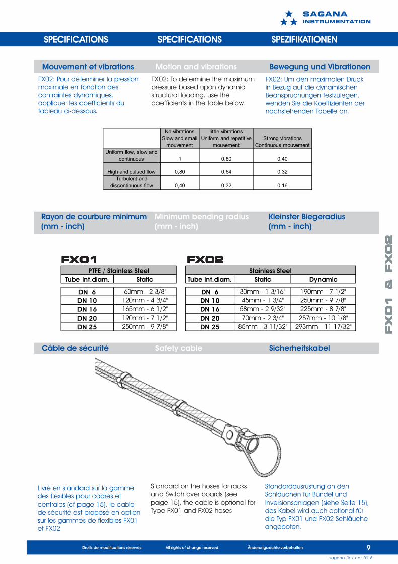
Tube int.diam. Static Tube int.diam. Static Dynamic
DN 6 60mm - 2 3/8" DN 6 30mm - 1 3/16" 190mm - 7 1/2"DN 10 120mm - 4 3/4" DN 10 45mm - 1 3/4" 250mm - 9 7/8"DN 16 165mm - 6 1/2" DN 16 58mm - 2 9/32" 225mm - 8 7/8"DN 20 190mm - 7 1/2" DN 20 70mm - 2 3/4" 257mm - 10 1/8"DN 25 250mm - 9 7/8" DN 25 85mm - 3 11/32" 293mm - 11 17/32"
Stainless SteelPTFE / Stainless Steel
Rayon de courbure minimum Minimum bending radius Kleinster Biegeradius(mm - inch) (mm - inch) (mm - inch)
Mouvement et vibrations Motion and vibrations Bewegung und Vibrationen
FX02: Pour déterminer la pressionmaximale en fonction descontraintes dynamiques,appliquer les coefficients dutableau ci-dessous.
No vibrations Slow and small
mouvement
little vibrations Uniform and repetitive
mouvementStrong vibrations
Continuous mouvement Uniform flow, slow and
continuous 1 0,80 0,40
High and pulsed flow 0,80 0,64 0,32Turbulent and
discontinuous flow 0,40 0,32 0,16
FX01FX01FX01FX01FX01 FX02FX02FX02FX02FX02
FX02: To determine the maximumpressure based upon dynamicstructural loading, use thecoefficients in the table below.
FX02: Um den maximalen Druckin Bezug auf die dynamischenBeanspruchungen festzulegen,wenden Sie die Koeffizienten dernachstehenden Tabelle an.
SPECIFICATIONS SPECIFICATIONS SPEZIFIKATIONEN
Livré en standard sur la gammedes flexibles pour cadres etcentrales (cf page 15), le cablede sécurité est proposé en optionsur les gammes de flexibles FX01et FX02
Standard on the hoses for racksand Switch over boards (seepage 15), the cable is optional forType FX01 and FX02 hoses
Standardausrüstung an denSchläuchen für Bündel undInversionsanlagen (siehe Seite 15),das Kabel wird auch optional fürdie Typ FX01 und FX02 Schläucheangeboten.
FX
01
&
FX
02
FX
01
&
FX
02
FX
01
&
FX
02
FX
01
&
FX
02
FX
01
&
FX
02
1 0sagana-flex-11-4
Droits de modifications réservés All rights of change reserved Änderungsrechte vorbehalten
����������������
FX(XX):FX01- PTFE/INOX
PTFE/StainlessSteelPTFE/Edelstahl
FX02 - Tout INOXAll StainlessSteelGanz Edelstahl
AAZZZ:Type et diametre du 1erraccord (voir page 12-13)AAM..- pour pas métriqueAA....”- pour poucesType and diameter of 1st
adapter (see pages 12-13)AAM – for metric systemAA – for inchesTyp und Durchmesser des 1.Anschluss (siehe Seite 12-13)AAM.. - für metrisches GewindeAA....”- für Zoll
AAZZZ:Type et diametre du 2eraccord (voir page 12-13)AAM..- pour pas métriqueAA....”- pour poucesType and diameter of 2nd
adapter (see pages 12-13)AAM – for metric systemAA – for inchesTyp und Durchmesser des 2.Anschluss (siehe Seite 12-13)AAM.. - für metrisches GewindeAA....”- für Zoll
LLLL:Longueur du flexible sansadaptateur. En mm ou...” pour poucesLength of hose withoutadapter. In mm or …” forinchesLänge des Schlauchsohne Adapter in mmoder ...” für Zoll
E:OptionsOptionsOptionen
Exemples: Example: Beispiel:
CODIFICATIONS ORDERING INFORMATION KODIFIKATION
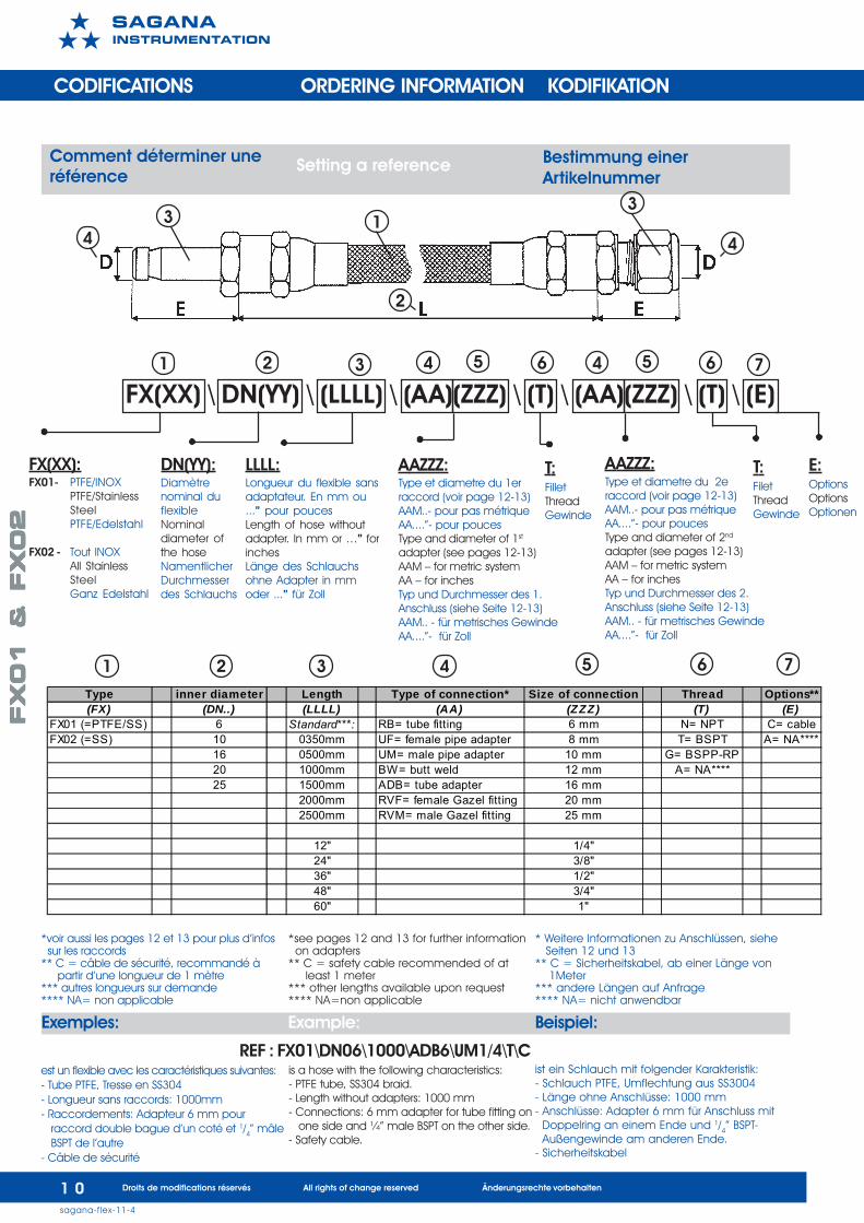
Comment déterminer uneréférence
Setting a reference Bestimmung einerArtikelnummer
1 2 3 4 5 6
*voir aussi les pages 12 et 13 pour plus d’infos sur les raccords** C = câble de sécurité, recommandé à partir d’une longueur de 1 mètre*** autres longueurs sur demande**** NA= non applicable
T:FiletThreadGewinde
REF : FX01\DN06\1000\ADB6\UM1/4\T\Cest un flexible avec les caractéristiques suivantes:- Tube PTFE, Tresse en SS304- Longueur sans raccords: 1000mm- Raccordements: Adapteur 6 mm pour raccord double bague d’un coté et 1/4” mâle BSPT de l’autre- Câble de sécurité
*see pages 12 and 13 for further information on adapters** C = safety cable recommended of at least 1 meter*** other lengths available upon request**** NA=non applicable
is a hose with the following characteristics:- PTFE tube, SS304 braid.- Length without adapters: 1000 mm- Connections: 6 mm adapter for tube fitting on one side and ¼” male BSPT on the other side.- Safety cable.
* Weitere Informationen zu Anschlüssen, siehe Seiten 12 und 13** C = Sicherheitskabel, ab einer Länge von 1Meter*** andere Längen auf Anfrage**** NA= nicht anwendbar
ist ein Schlauch mit folgender Karakteristik:- Schlauch PTFE, Umflechtung aus SS3004- Länge ohne Anschlüsse: 1000 mm- Anschlüsse: Adapter 6 mm für Anschluss mit Doppelring an einem Ende und 1/4” BSPT- Außengewinde am anderen Ende.- Sicherheitskabel
3 1
2
4
3
4
T:FilletThreadGewinde
1 2 3 74 65
FX(XX) \ DN(YY) \ (LLLL) \ (AA)(ZZZ) \ (T) \ (AA)(ZZZ) \ (T) \ (E)
Type inner diameter Length Type of connection* Size of connection Thread Options**(FX) (DN..) (LLLL) (AA) (ZZZ) (T) (E)
FX01 (=PTFE/SS) 6 Standard***: RB= tube fitting 6 mm N= NPT C= cableFX02 (=SS) 10 0350mm UF= female pipe adapter 8 mm T= BSPT A= NA****
16 0500mm UM= male pipe adapter 10 mm G= BSPP-RP20 1000mm BW= butt weld 12 mm A= NA****25 1500mm ADB= tube adapter 16 mm
2000mm RVF= female Gazel fitting 20 mm2500mm RVM= male Gazel fitting 25 mm
12" 1/4"24" 3/8"36" 1/2"48" 3/4"60" 1"
DN(YY):Diamètrenominal duflexibleNominaldiameter ofthe hoseNamentlicherDurchmesserdes Schlauchs
7
4 65
FX
01
&
FX
02
FX
01
&
FX
02
FX
01
&
FX
02
FX
01
&
FX
02
FX
01
&
FX
02
1 1sagana-flex-11-4
Droits de modifications réservés All rights of change reserved Änderungsrechte vorbehalten
����������������
CODIFICATIONS ORDERING INFORMATION KODIFIKATION
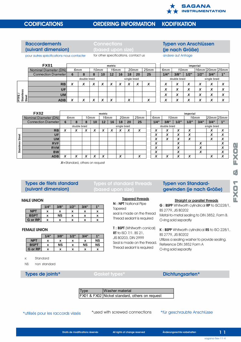
Raccordements(suivant dimension)pour autres spécifications nous contacter
Connections(based upon size)for other specifications, contact us
Typen von Anschlüssen(je nach Größe)andere auf Anfrage
X=Standard, others on request
Types de filets standard(suivant dimension)
Types of standard threads(based upon size)
Typen von Standard-gewinden (je nach Größe)
x: Standard
NS: non standard
Types de joints* Gasket types* Dichtungsarten*
Tapered threadsN : NPT National PipeTaperedseal is made on the threadThread sealant is required
T : BSPT (Whitworth conical)RT to ISO 7/1. BS 21,JIS B0203, DIN 2999Seal is made on the thread.Thread sealant is required
Straight or parallel threadsG : BSPP Whitworth cylindrical RP to ISO228/1,BS 2779, JIS B0202Metal-to-metal sealing to DIN 3852, Form B.O-ring sold separatly
K : BSPP Whitworth cylindrical RS to ISO 228/1,BS 2779, JIS B0202Utilizes a sealing washer to provide sealing.Reference DIN 3852 Form AO-ring sold separatly
Type Washer materialFX01 & FX02 Nickel standard, others on request
*utilisés pour les raccords vissés *used with screwed connections *für geschraubte Anschlüsse
1/4" 3/8" 1/2" 3/4" 1"NPT x x x x x
BSPT x NS x x xG or RP x x x x x
1/4" 3/8" 1/2" 3/4" 1"NPT x x x x NS
BSPT x NS x NS NSG or RP x x x x x
MALE UNION
FEMALE UNION
FX01Nominal Diameter (DN) 25mm 6mm 16mm 20mm 25mm
Connection Diameter 6 8 8 10 12 16 18 20 25 1/4" 3/8" 1/2" 1/2" 3/4" 1"
RB X X X X X X X X X X X X X X XUF X X X X X XUM X X X X X X
ADB X X X X X X X X X X X X X
single braid
metric20mm10mm 16mm
double braid single braid
imperial10mm
double braid
PTFE
/
St
ainl
ess
Stee
l
6mm
Nominal Diameter (DN) 25mm 6mm 20mm 25mmConnection Diameter 6 8 8 10 12 16 18 20 25 1/4" 3/8" 1/2" 1/2" 3/4" 3/4" 1"
RB X X X X X X X X X X X X X X XUF X X X X X XUM X X X X X X
RVF X X X XRVM X X X X
BW X X X XADB X X X X X X X X X X X X X
16mm 10mm 16mm
Stai
nles
s St
eel
double braid single braid
6mmimperialmetricFX02
double braid single braid
20mm10mm
FX
01
&
FX
02
FX
01
&
FX
02
FX
01
&
FX
02
FX
01
&
FX
02
FX
01
&
FX
02
1 2sagana-flex-11-4
Droits de modifications réservés All rights of change reserved Änderungsrechte vorbehalten
����������������
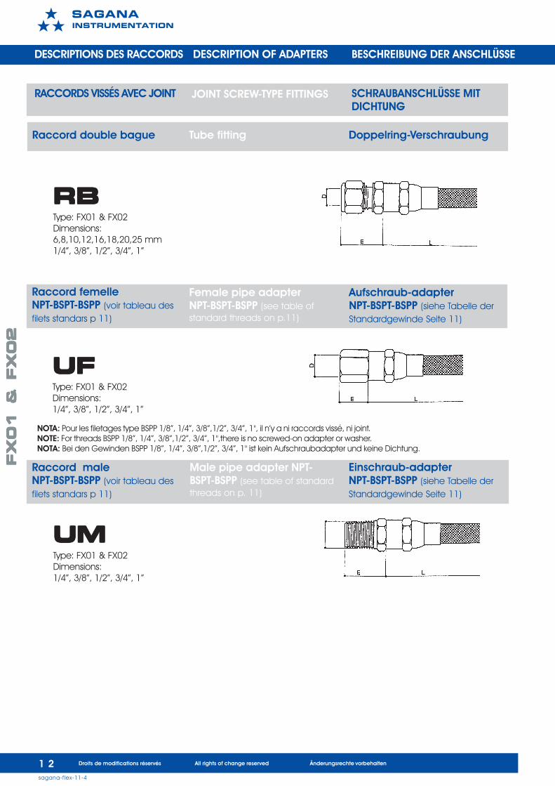
Raccord femelleNPT-BSPT-BSPP (voir tableau desfilets standars p 11)
Female pipe adapterNPT-BSPT-BSPP (see table ofstandard threads on p.11)
Aufschraub-adapterNPT-BSPT-BSPP (siehe Tabelle derStandardgewinde Seite 11)
UFUFUFUFUFType: FX01 & FX02Dimensions:1/4”, 3/8”, 1/2”, 3/4”, 1”
Raccord double bague Tube fitting Doppelring-Verschraubung
RBRBRBRBRBType: FX01 & FX02Dimensions:6,8,10,12,16,18,20,25 mm1/4”, 3/8”, 1/2”, 3/4”, 1”
Raccord maleNPT-BSPT-BSPP (voir tableau desfilets standars p 11)
Einschraub-adapterNPT-BSPT-BSPP (siehe Tabelle derStandardgewinde Seite 11)
Male pipe adapter NPT-BSPT-BSPP (see table of standardthreads on p. 11)
UMUMUMUMUMType: FX01 & FX02Dimensions:1/4”, 3/8”, 1/2”, 3/4”, 1”
RACCORDS VISSÉS AVEC JOINT JOINT SCREW-TYPE FITTINGS SCHRAUBANSCHLÜSSE MITDICHTUNG
DESCRIPTIONS DES RACCORDS DESCRIPTION OF ADAPTERS BESCHREIBUNG DER ANSCHLÜSSE
NOTA: Pour les filetages type BSPP 1/8”, 1/4”, 3/8”,1/2”, 3/4”, 1", il n’y a ni raccords vissé, ni joint.NOTE: For threads BSPP 1/8”, 1/4”, 3/8”,1/2”, 3/4”, 1",there is no screwed-on adapter or washer.NOTA: Bei den Gewinden BSPP 1/8”, 1/4”, 3/8”,1/2”, 3/4”, 1" ist kein Aufschraubadapter und keine Dichtung.
FX
01
&
FX
02
FX
01
&
FX
02
FX
01
&
FX
02
FX
01
&
FX
02
FX
01
&
FX
02
1 3sagana-flex-11-4
Droits de modifications réservés All rights of change reserved Änderungsrechte vorbehalten
����������������
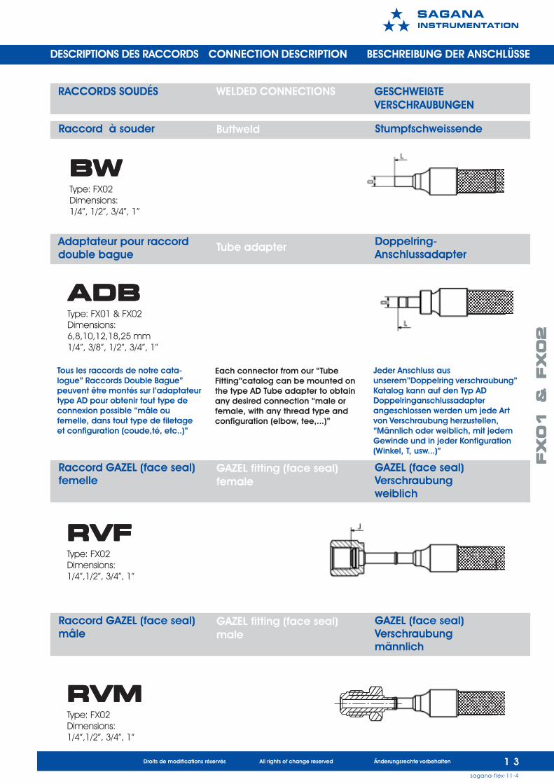
Raccord GAZEL (face seal)femelle
GAZEL fitting (face seal)female
GAZEL (face seal)Verschraubungweiblich
RVFRVFRVFRVFRVFType: FX02Dimensions:1/4”,1/2”, 3/4”, 1”
Adaptateur pour raccorddouble bague
Doppelring-Anschlussadapter
Tube adapter
ADBADBADBADBADBType: FX01 & FX02Dimensions:6,8,10,12,18,25 mm1/4”, 3/8”, 1/2”, 3/4”, 1”
RACCORDS SOUDÉS WELDED CONNECTIONS GESCHWEIßTEVERSCHRAUBUNGEN
DESCRIPTIONS DES RACCORDS CONNECTION DESCRIPTION BESCHREIBUNG DER ANSCHLÜSSE
Raccord à souder Buttweld Stumpfschweissende
BWBWBWBWBWType: FX02Dimensions:1/4”, 1/2”, 3/4”, 1”
Raccord GAZEL (face seal)mâle
GAZEL fitting (face seal)male
GAZEL (face seal)Verschraubungmännlich
RVMRVMRVMRVMRVMType: FX02Dimensions:1/4”,1/2”, 3/4”, 1”
Tous les raccords de notre cata-logue” Raccords Double Bague”peuvent être montés sur l’adaptateurtype AD pour obtenir tout type deconnexion possible “mâle oufemelle, dans tout type de filetageet configuration (coude,té, etc..)”
Each connector from our “TubeFitting”catalog can be mounted onthe type AD Tube adapter to obtainany desired connection “male orfemale, with any thread type andconfiguration (elbow, tee,...)”
Jeder Anschluss ausunserem”Doppelring verschraubung”Katalog kann auf den Typ ADDoppelringanschlussadapterangeschlossen werden um jede Artvon Verschraubung herzustellen,“Männlich oder weiblich, mit jedemGewinde und in jeder Konfiguration(Winkel, T, usw...)”
FX
01
&
FX
02
FX
01
&
FX
02
FX
01
&
FX
02
FX
01
&
FX
02
FX
01
&
FX
02
1 4sagana-flex-11-4
Droits de modifications réservés All rights of change reserved Änderungsrechte vorbehalten
����������������
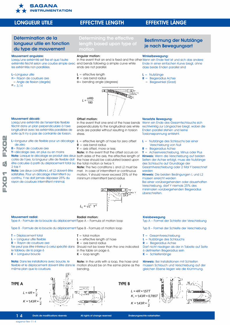
Détermination de lalongueur utile en fonctiondu type de mouvement
Determining the effectivelength based upon type ofmotion
Bestimmung der Nutzlängeje nach Bewegungsart
LONGUEUR UTILE EFFECTIVE LENGTH EFFEKTIVE LÄNGE
ION
Mouvement angulaire:Lorsqu’une extrémité est fixe et que l’autreextrémité fléchit selon une courbe simple avecles extrémités non parallèles.
L=Longueur utileR= Rayon de courbure axe = Angle de flexion (degrés) = 3,14
Mouvement décalé:Lorsqu’une extrémité de l’ensemble flexiblefléchit dans un plan perpendiculaire à l’axelongitudinal avec les extrémités parallèles desorte qu’il n’y a pas de contrainte de torsion.
L=longueur utile de flexible pour un décalage de zéroR= Rayon de courbure axeY=décalage axe, en plus ou en moinsNota: Lorsque le décalage se produit des deuxcotés de l’axe, la longueur utile de flexible doitêtre calculée à partir du déplacement total ou2 fois YNota: Les deux conditions L et L2 doivent êtresatisfaites. Pour un décalage intermittent oucontinu, Y ne doit jamais dépasser 25% durayon de courbure intermittent minimal.
Mouvement radial:Type A - Formule de la boucle du déplacement
Type B - Formule de la boucle du déplacement
T = Déplacement totalL = Longueur utile flexibleR = Rayon de courbure axeNe peut pas être inferieur à celui spécifié dansle tableau de la page 6K = Longueur boucle
Nota: Dans les installations avec boucle, leflexible et le déplacement doivent être dans lemême plan que la courbure.
180Θ
=Rπ
L
π
222 = YLL
2+43,1=
2+4=
TRK
TRL
2+43,1=
785,0+43,1=57,1+4=
1
TRK
TRKTRL
Angular motion:In the event that an end is fixed and the otherend bends following a simple curve whileends are not parallel.
L = effective lengthR = axis bend radius = bending angle (degrees)
Offset motion:In the event that one end of the hose bendsperpendicularly to the longitudinal axis whileends are parallel without resulting in torsionstress.
L = effective length of hose for zero offsetR = axis bend radiusY = axis offset, more or less.Note: In the event that the offset occurs onboth sides of the axis, the effective length ofthe hose should be calculated based uponthe total motion or twice Y.Note: The two conditions L and L2 must bemet. In case of intermittent or continuousmotion, Y should never exceed 25% of theminimum intermittent bend radius
Radial motion:Type A – Formula of motion loop
Type B - Formula of motion loop
T = total motionL = effective length of hoseR = axis bend radiusShould not be lower than the one indicatedin the table on page 6.K = loop length
Note: In the units with a loop, the hose andmotion should be on the same plane as thebending.
Winkelbewegung:Wenn ein Ende fest ist und sich das andereEnde in einer einfachen Kurve biegt, ohnedass beide Enden parallel sind
L = NutzlängeR = Biegeradius Achse = Biegewinkel (Grad)
Versetzte Bewegung:Wenn ein Ende des Gesamtschlauchs sichrechtwinklig zur Längsachse biegt, wobei dieEnden parallel stehen und keineTorsionsspannung entsteht.
L = Nutzlänge des Schlauchs bei einer Verschiebung von NullR = Biegeradius AchseY = Achsenverschiebung, Minus oder PlusHinweis: Wenn die Verschiebung auf beidenSeiten der Achse erfolgt, muss die Nutzlängedes Schlauchs auf Grundlage derGesamtverschiebung oder 2 Mal Y berechnetwerdenHinweis: Die beiden Bedingungen L und L2müssen erreicht werdenBei einer vorübergehenden oder dauerhaftenVerschiebung, darf Y niemals 25% desminimalen vorübergehenden Biegeradiusüberschreiten.
KreisbewegungTyp A – Formel der Schleife der Verschiebung
Typ B – Formel der Schleife der Verschiebung
T = GesamtverschiebungL = Nutzlänge des SchlauchsR = Biegeradius AchseDarf nicht niedriger als der in Tabelle auf Seite6 definierten Biegeradius seinK = Schleifenlänge
Hinweis: Bei Installationen mit Schleifenmüssen Schlauch und Verschiebung auf dergleichen Ebene liegen wie die Krümmung.
Θ
TYPE A TYPE B
FX
01
&
FX
02
FX
01
&
FX
02
FX
01
&
FX
02
FX
01
&
FX
02
FX
01
&
FX
02
1 5sagana-flex-11-4
Droits de modifications réservés All rights of change reserved Änderungsrechte vorbehalten
����������������
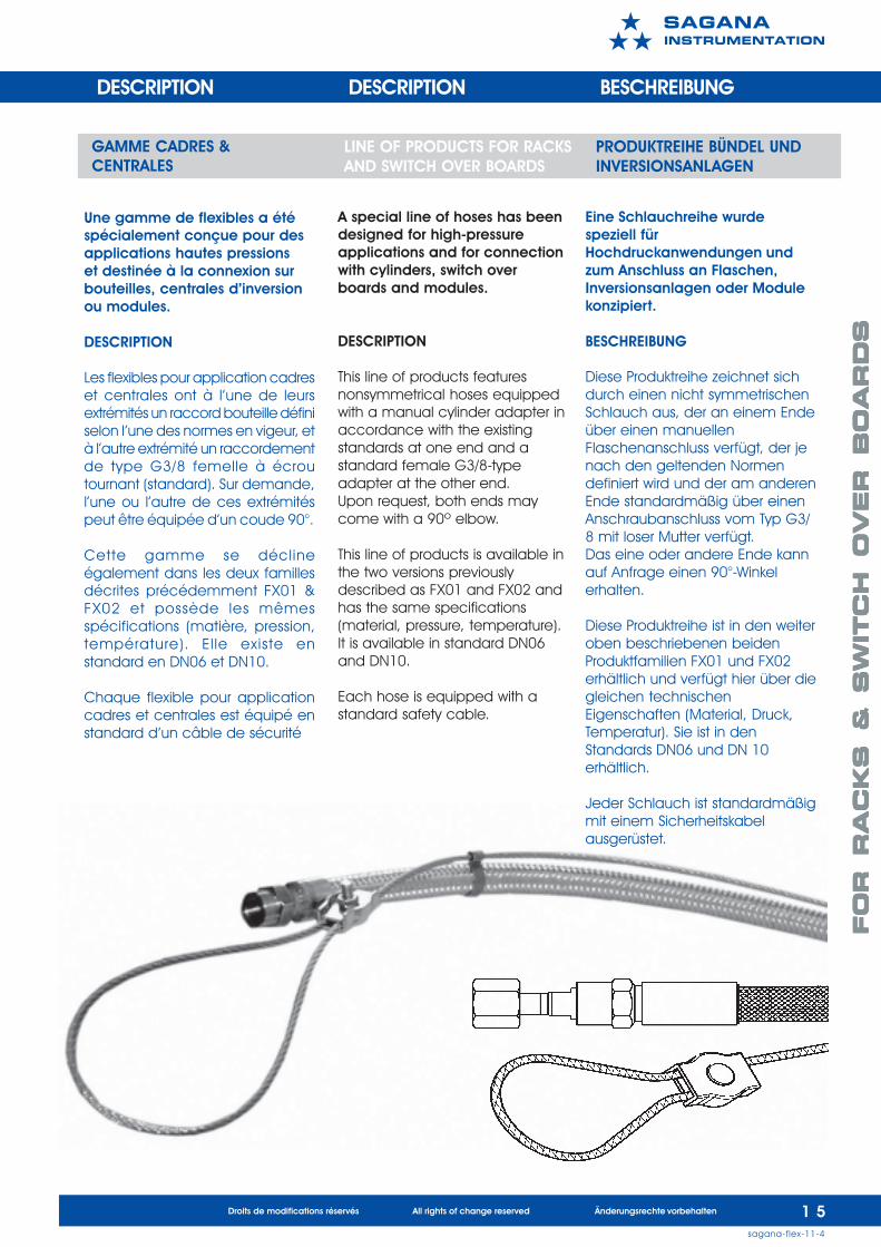
Une gamme de flexibles a étéspécialement conçue pour desapplications hautes pressionset destinée à la connexion surbouteilles, centrales d’inversionou modules.
DESCRIPTION
Les flexibles pour application cadreset centrales ont à l’une de leursextrémités un raccord bouteille définiselon l’une des normes en vigeur, età l’autre extrémité un raccordementde type G3/8 femelle à écroutournant (standard). Sur demande,l’une ou l’autre de ces extrémitéspeut être équipée d’un coude 90°.
Cette gamme se déclineégalement dans les deux famillesdécrites précédemment FX01 &FX02 et possède les mêmesspécifications (matière, pression,température). El le existe enstandard en DN06 et DN10.
Chaque flexible pour applicationcadres et centrales est équipé enstandard d’un câble de sécurité
GAMME CADRES &CENTRALES
LINE OF PRODUCTS FOR RACKSAND SWITCH OVER BOARDS
PRODUKTREIHE BÜNDEL UNDINVERSIONSANLAGEN
A special line of hoses has beendesigned for high-pressureapplications and for connectionwith cylinders, switch overboards and modules.
DESCRIPTION
This line of products featuresnonsymmetrical hoses equippedwith a manual cylinder adapter inaccordance with the existingstandards at one end and astandard female G3/8-typeadapter at the other end.Upon request, both ends maycome with a 90º elbow.
This line of products is available inthe two versions previouslydescribed as FX01 and FX02 andhas the same specifications(material, pressure, temperature).It is available in standard DN06and DN10.
Each hose is equipped with astandard safety cable.
Eine Schlauchreihe wurdespeziell fürHochdruckanwendungen undzum Anschluss an Flaschen,Inversionsanlagen oder Modulekonzipiert.
BESCHREIBUNG
Diese Produktreihe zeichnet sichdurch einen nicht symmetrischenSchlauch aus, der an einem Endeüber einen manuellenFlaschenanschluss verfügt, der jenach den geltenden Normendefiniert wird und der am anderenEnde standardmäßig über einenAnschraubanschluss vom Typ G3/8 mit loser Mutter verfügt.Das eine oder andere Ende kannauf Anfrage einen 90°-Winkelerhalten.
Diese Produktreihe ist in den weiteroben beschriebenen beidenProduktfamilien FX01 und FX02erhältlich und verfügt hier über diegleichen technischenEigenschaften (Material, Druck,Temperatur). Sie ist in denStandards DN06 und DN 10erhältlich.
Jeder Schlauch ist standardmäßigmit einem Sicherheitskabelausgerüstet.
DESCRIPTION DESCRIPTION BESCHREIBUNG
FO
R R
AC
KS
&
S
WIT
CH
O
VER
B
OA
RD
SFO
R R
AC
KS
&
S
WIT
CH
O
VER
B
OA
RD
SFO
R R
AC
KS
&
S
WIT
CH
O
VER
B
OA
RD
SFO
R R
AC
KS
&
S
WIT
CH
O
VER
B
OA
RD
SFO
R R
AC
KS
&
S
WIT
CH
O
VER
B
OA
RD
S
1 6sagana-flex-11-4
Droits de modifications réservés All rights of change reserved Änderungsrechte vorbehalten
����������������
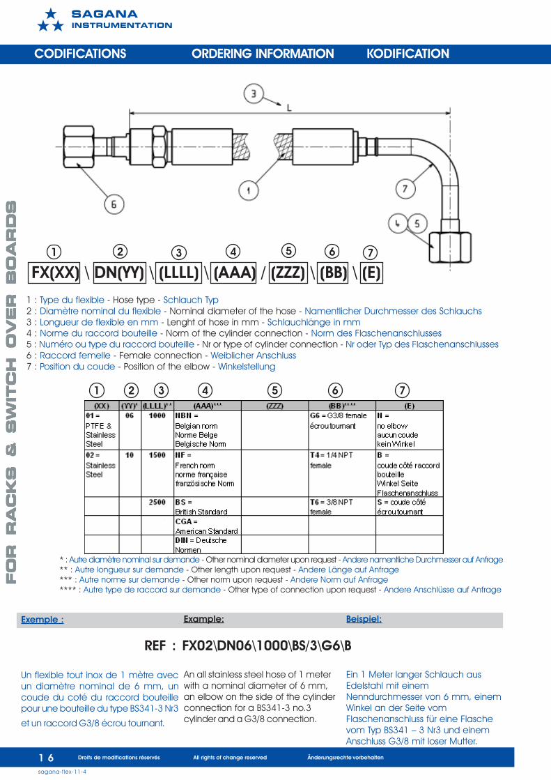
FX(XX) \ DN(YY) \ (LLLL) \ (AAA) / (ZZZ) \ (BB) \ (E)
CODIFICATIONS ORDERING INFORMATION KODIFICATION
1 2 3 74 65
Exemple :
Un flexible tout inox de 1 mètre avecun diamètre nominal de 6 mm, uncoude du coté du raccord bouteillepour une bouteille du type BS341-3 Nr3
et un raccord G3/8 écrou tournant.
1 2 3 74 65
1 : Type du flexible - Hose type - Schlauch Typ2 : Diamètre nominal du flexible - Nominal diameter of the hose - Namentlicher Durchmesser des Schlauchs3 : Longueur de flexible en mm - Lenght of hose in mm - Schlauchlänge in mm4 : Norme du raccord bouteille - Norm of the cylinder connection - Norm des Flaschenanschlusses5 : Numéro ou type du raccord bouteille - Nr or type of cylinder connection - Nr oder Typ des Flaschenanschlusses6 : Raccord femelle - Female connection - Weiblicher Anschluss7 : Position du coude - Position of the elbow - Winkelstellung
* : Autre diamètre nominal sur demande - Other nominal diameter upon request - Andere namentliche Durchmesser auf Anfrage** : Autre longueur sur demande - Other length upon request - Andere Länge auf Anfrage*** : Autre norme sur demande - Other norm upon request - Andere Norm auf Anfrage**** : Autre type de raccord sur demande - Other type of connection upon request - Andere Anschlüsse auf Anfrage
Example:
An all stainless steel hose of 1 meterwith a nominal diameter of 6 mm,an elbow on the side of the cylinderconnection for a BS341-3 no.3cylinder and a G3/8 connection.
Beispiel:
Ein 1 Meter langer Schlauch ausEdelstahl mit einemNenndurchmesser von 6 mm, einemWinkel an der Seite vomFlaschenanschluss für eine Flaschevom Typ BS341 – 3 Nr3 und einemAnschluss G3/8 mit loser Mutter.
REF : FX02\DN06\1000\BS/3\G6\B
FO
R R
AC
KS
&
S
WIT
CH
O
VER
B
OA
RD
SFO
R R
AC
KS
&
S
WIT
CH
O
VER
B
OA
RD
SFO
R R
AC
KS
&
S
WIT
CH
O
VER
B
OA
RD
SFO
R R
AC
KS
&
S
WIT
CH
O
VER
B
OA
RD
SFO
R R
AC
KS
&
S
WIT
CH
O
VER
B
OA
RD
S
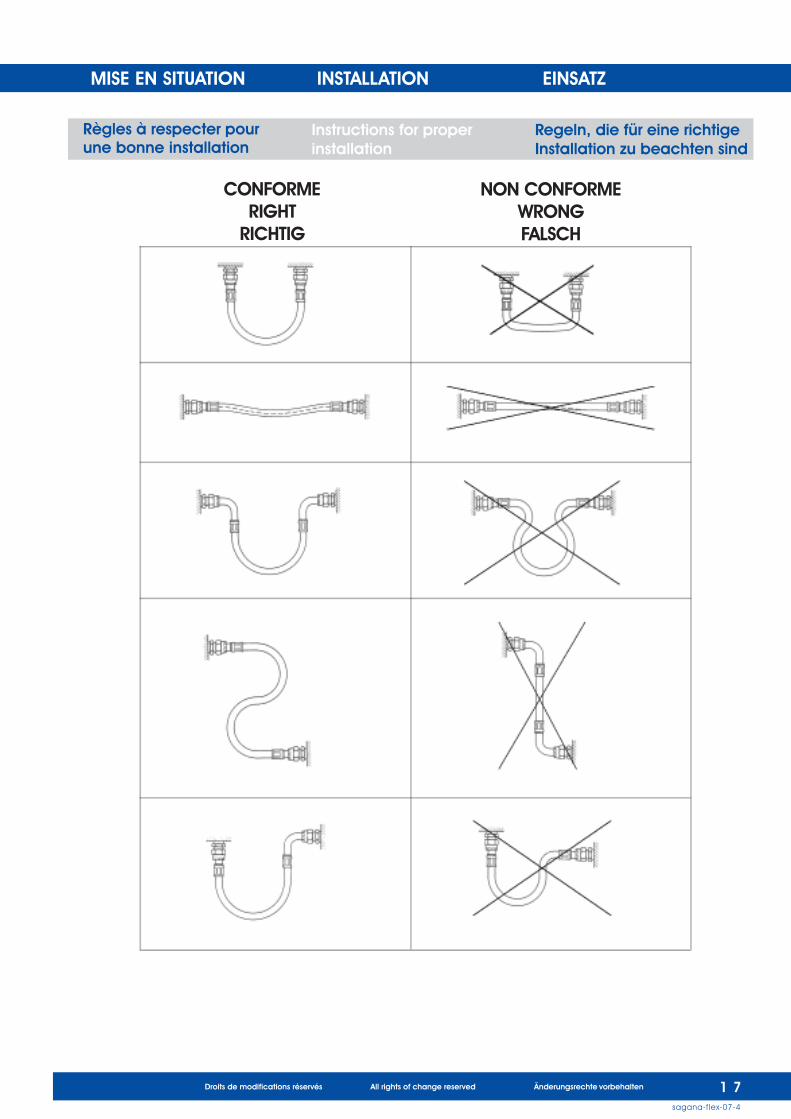
MISE EN SITUATION INSTALLATION EINSATZ
Règles à respecter pourune bonne installation
Instructions for properinstallation
Regeln, die für eine richtigeInstallation zu beachten sind
CONFORMERIGHT
RICHTIG
NON CONFORMEWRONGFALSCH
1 7sagana-flex-07-4
Droits de modifications réservés All rights of change reserved Änderungsrechte vorbehalten
1 8sagana-flex-cat-01-6
����������������
Droits de modifications réservés All rights of change reserved Änderungsrechte vorbehalten
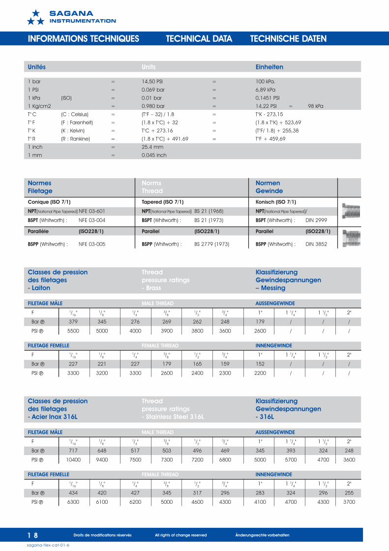
Unités Units Einheiten
1 bar = 14,50 PSI = 100 kPa.
1 PSI = 0.069 bar = 6,89 kPa
1 kPa (ISO) = 0.01 bar = 0,1451 PSI
1 Kg/cm2 = 0.980 bar = 14,22 PSI = 98 kPa
T° C (C : Celsius) = (T°F – 32) / 1.8 = T°K - 273,15
T° F (F : Farenheit) = (1.8 x T°C) + 32 = (1.8 x T°K) + 523,69
T° K (K : Kelvin) = T°C + 273.16 = (T°F/ 1.8) + 255,38
T° R (R : Rankine) = (1.8 x T°C) + 491.69 = T°F + 459,69
1 inch = 25.4 mm
1 mm = 0.045 inch
Normes Norms NormenFiletage Thread Gewinde
Conique (ISO 7/1) Tapered (ISO 7/1) Konisch (ISO 7/1)
NPT(National Pipe Tapered) NFE 03-601 NPT(National Pipe Tapered) BS 21 (1968) NPT(National Pipe Tapered)/
BSPT (Whitworth) : NFE 03-004 BSPT (Whitworth) : BS 21 (1973) BSPT (Whitworth) : DIN 2999
Parallèle (ISO228/1) Parallel (ISO228/1) Parallel (ISO228/1)
BSPP (Whitworth) : NFE 03-005 BSPP (Whitworth) : BS 2779 (1973) BSPP (Whitworth) : DIN 3852
Classes de pression Thread Klassifizierungdes filetages pressure ratings Gewindespannungen- Laiton - Brass – Messing
FILETAGE MÂLE MALE THREAD AUSSENGEWINDE
F 1/16"1/8"
1/4"3/8"
1/2"3/4" 1" 1 1/4" 1 1/2" 2"
Bar . 379 345 276 269 262 248 179 / / /
PSI . 5500 5000 4000 3900 3800 3600 2600 / / /
FILETAGE FEMELLE FEMALE THREAD INNENGEWINDE
F 1/16"1/8"
1/4"3/8"
1/2"3/4" 1" 1 1/4" 1 1/2" 2"
Bar . 227 221 227 179 165 159 152 / / /
PSI . 3300 3200 3300 2600 2400 2300 2200 / / /
Classes de pression Thread Klassifizierungdes filetages pressure ratings Gewindespannungen- Acier Inox 316L - Stainless Steel 316L - 316L
FILETAGE MÂLE MALE THREAD AUSSENGEWINDE
F 1/16"1/8"
1/4"3/8"
1/2"3/4" 1" 1 1/4" 1 1/2" 2"
Bar . 717 648 517 503 496 469 345 393 324 248
PSI . 10400 9400 7500 7300 7200 6800 5000 5700 4700 3600
FILETAGE FEMELLE FEMALE THREAD INNENGEWINDE
F 1/16"1/8"
1/4"3/8"
1/2"3/4" 1" 1 1/4" 1 1/2" 2"
Bar . 434 420 427 345 317 296 283 324 296 255
PSI 6300 6100 6200 5000 4600 4300 4100 4700 4300 3700
INFORMATIONS TECHNIQUES TECHNICAL DATA TECHNISCHE DATEN
sagana-flex-cat-01-6
����������������
Droits de modifications réservés All rights of change reserved Änderungsrechte vorbehalten 1 9
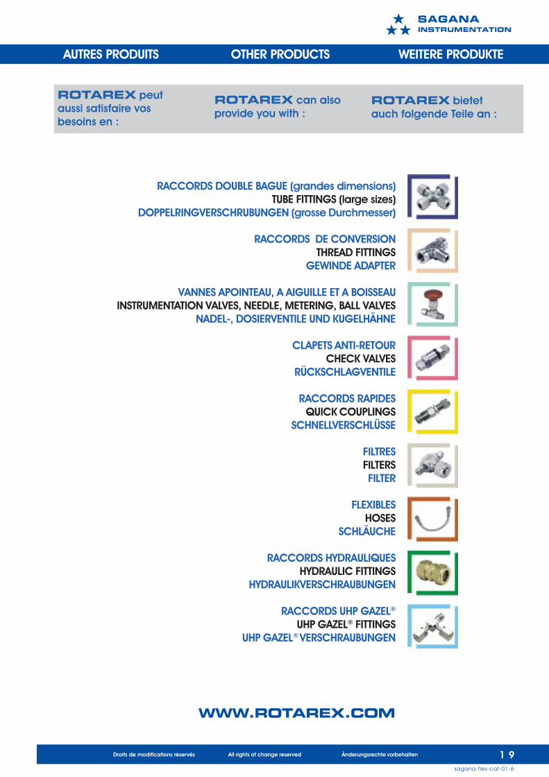
AUTRES PRODUITS OTHER PRODUCTS WEITERE PRODUKTE
RACCORDS DOUBLE BAGUE (grandes dimensions)TUBE FITTINGS (large sizes)
DOPPELRINGVERSCHRUBUNGEN (grosse Durchmesser)
RACCORDS DE CONVERSIONTHREAD FITTINGS
GEWINDE ADAPTER
VANNES APOINTEAU, A AIGUILLE ET A BOISSEAUINSTRUMENTATION VALVES, NEEDLE, METERING, BALL VALVES
NADEL-, DOSIERVENTILE UND KUGELHÄHNE
CLAPETS ANTI-RETOURCHECK VALVES
RÜCKSCHLAGVENTILE
RACCORDS RAPIDESQUICK COUPLINGS
SCHNELLVERSCHLÜSSE
FILTRESFILTERSFILTER
FLEXIBLESHOSES
SCHLÄUCHE
RACCORDS HYDRAULIQUESHYDRAULIC FITTINGS
HYDRAULIKVERSCHRAUBUNGEN
RACCORDS UHP GAZEL®
UHP GAZEL® FITTINGSUHP GAZEL® VERSCHRAUBUNGEN
ROTAREX peutaussi satisfaire vosbesoins en :
ROTAREX can alsoprovide you with :
ROTAREX bietetauch folgende Teile an :
WWW.ROTAREX.COM

e-mail: [email protected]
website: www.rotarex.com
����������������
Headquarters Luxembourg
information
���� �����