Embed Size (px)
Citation preview

Flexible Routing and Addressing For a Next Generation
Paul Francis
NTT Software Laboratories
Tokyo, Japan
francis@slab. ntt
Abstract
Due to a limbed address space and poor scaling of backbone routing
information, the Intemet Protocol (W) is rapidly reaching the end
of its useful lifetime. The Simple Intemet Protocol Plus (SIPP), a
proposed next generation Intemet Protocol, solves these problems
with larger intemet layer addresses. In addition, SIPP provides a
number of advanced routing and addressing capabilities including
mobility, extended (variable-length) addressing, provider selection,
and certain forms of multicast. These capabilities are all achieved
through a single mechanism, a generalization of the IP loose source
route. We argue tha~ for reasons of simplicity and evolvability,
a single powerful mechanism to achieve a wide range of routing
and addressing functions is preferable to having multiple specilic
mechanisms, one for each function.
1 Introduction
The Irttemet Protocol (P, [18]) is rapidly reaching the end of its
useful life as a global intemetwork protocol. Fundamentally, the
IP address space is too small to indefinitely satisfy current htemet
growth rates [10]. It is difficult to accurately predict when IP
addresses will nm out, but most estimates range from 5 to 10 years.
A related problem with IP is poor scaliig of intemet routing.
IP routing has historically scaled proportional to the number of IP
networks, which is on the order of the number of organizations using
IF? Classless Inter-Domain Routing (CIDR) [9], a technique which
proposes changes in the definition and allocation of IP addresses,
may alleviate this problem in the short term. Whh CIDR, scaling
in routing can be nearly proportional to the number of IP service
providers (also called B? backbones). Some of the scaling benefits
are lost if many organizations choose to change service providers
without renumbering their networks to reflect provider attachments,
or many organizations are each connected to more than one provider.
To find a longer term solution to these problems, the IETF (htter-
net Engineering Task Force—the standards body with oversight of
o~i~ work ~a~ pa~ial]y finded by the Advanced Research Prokcts
Agency (ARPA) under contract No. DABT63-93-C-O042.
Permission to copy without fee all or part of this material isgranted provided that the copies are not made or distributed fordirect commercial advantage, the ACM copyright notice and thetitle of the publication and its date appear, and notice is giventhat copying is by permission of the Association of ComputingMachinery. To copy otherwise, or to republish, requires a feeand/or specific permission.SIGCOMM 94 -8/94 London England UKQ 1994 ACM 0-89791 -682-4/94/0008..$3.50
Rarnesh Govindan
Bell Communications Research
Morristown, NJ, USA
rxg@thumper. bellcore. com
TCP/lP and related protocols) has initiated a standardntion effort
for the next generatwn E’ (lpng), a replacement protocol for II?
Fug is required to solve the address depletion and scaling problems
of IP. In addition, lpng may add new features to IP.
A number of protocols (Pip [7], SIP [4], and TUBA [15]) have
been proposed for IPng. All of the proposals solve the basic prob-
lems of scaling and address depletion by using larger intemet layer
addresses. A recent proposal, SIPP (the Simple Intemet Protocol
Plus), uses SIP’S syntax but borrows some of Pip’s advanced routing
and addressing featmes.
SIPP’S advanced routing and addressing mechanism is a gener-
alization of IP’s loose source route. This mechanism enables such
features as variable-length addressing, mobitity, automatic host ad-
dress configuration, and provider selection. Moreover, the mecha-
nism is desiguedto be flexible and evolvable, allowing new routing
and addressing features to be incorporated relatively easily into the
Iutemet.
2 Overview
The mechanism for obtaining advanced routing and addressing fea-
tures from SIPP is a generalization of the loose source route mech-
anism of IP. IiI SIPP, the analogous mechanism is called the rouring
header. The SIPP routing header encodes a list of SIPP addresses
in the packet header (see Section 7). This list of addresses is called
a route sequence. Each address in this list identifies an intermediate
destination (a target) on the path to the final destination. The in-
termediate destination to be visited next is called the active target.
In au IP loose source route, targets are individual nodes (hosts or
routers). In SIPP, targets can be individual nodes, or any node in a
cluster of nodes.
When it receives a packe~ a node compares the active target in
the route sequence against a set of addresses it has stored. This is
the set of addresses for which tie node is a target. If the comparison
succeeds, the next target in the route sequence becomes the active
target. This way, the packet visits each target listed in the routesequence.
At first glance, the number of uses for this mechanism appears
to be rather limited. Indeed, IP hosts use the loose source route
mechanism very infrequently. Jn actual fac~ however, virtually
all known routing mechanisms can be modeled as loose source
routes [8]. For instance, routing on hierarchical addresses-the
most common form of routing in the fntemet-rm be modeled as
a loose source route, as we now show.
An IP hierarchical address has three levels; network, subne~ and
host. Conceptually, when a packet is routed to an IP address, routers
116
initially examine the network number. When the packet reaches a
router within the addressed ttetwork, that router forwards the packet
towards the addressed subnet. Firtally, when the packet reaches
a router on the subne~ that router examines the host number and
routes the packet to the addressed host. In loose source routing
terms, this packet can be said to have traversed two intermediate
targets, the network and subne~ on its way to the destination host.
There are differences between processing a source route and a hier-
archical address. For example, when processing a source route, the
active target is explicitly labeled, and it is not necessary to examine
previous (already visited) targets; with a hierarchical address, all
previous targets @hierarchical numbers) must be examined by each
router. Such differences, however, are mechanistic not semantic. It
is possible to obtain the semantics of a hierarchical address using the
mechanics of a source route. This approach, in its full generality,
was iirst used in Pip [7].
In this paper, we show how the generalized source route mech-
anism is used in SIPP to achieve jiexibk routing and addressing
features. In particular, we illustrate how mobile routing, variable-
length addressing, provider selection, and certain forms of mtrhicast
routing maybe modeled usingtbis mechanism. For these features to
work correctly, every SIPP node should be able to reverse the order
of addresses in a received route sequence, and use the resulting route
sequence to return tbe packet to the originator. We also show how
this ability of SIPP nodes to reverse route sequences also enables
an incremental evolution of the intemet towards new routing and
addressing paradigms that can be modeled using route sequences.
The remainder of the paper is organized as follows. Section 3
descriies the format and assignment of SIPP addresses. Section 4
discusses the rules for route sequence reversal by nodes. The
use of route sequences to model advanced routing and address-
ing paradigms is illustrated in Section 5. Section 6 describes how
the use of route sequences impacts routing algorithms and address
assignment. Section 7 lists performance, flexibility and security im-
plications of the use of route sequences. Section 8 discusses related
work and Section 9 summarizes the contributions of this paper.
3 Addresses and Address Sequences
A route sequence is a list of SIPP addresses. Like the IP address, a
SIPP address serves two purposey 1) it identifies a node or a group
of nodes, and 2) it may specify a node’s network location to aid the
routing function.
Abstractly, a route sequence in a SIPP packet encodes the lo-
cation of the source and destination in the intemet (among other
information). We allow the location of a SIPP node to be specitied
by an address sequence which is an ordered list of one or more
64-bit SIPP addresses.
This section describes SIPP addresses and address sequences in
greater detail.
3.1 SIPP Address Types
Two types of packet delivery services are supported in SIPP. With
multicast service, a packet is (unreliably) delivered to all of the
nodes identified by the address. With unicast service, a packet is
(unreliably) delivered to exactly one node. The destination address
in a SIPP packet determines the type of delivery service given to
the packet. Thus, SIPP addresses fall into two classes: unicast
and multicast. Multicast and unicast addresses are assigned from
the same 64-bit address space, but are distinguished by multicast
addresses having a fixed prefix. A SIPP address’ identification
function does not necessarily imply a packet delivery service; for
example, a unicast address can identify a set of nodes (see below).
This section describes tmicast and multicast SIPP addresses. As
of this writing, SIPP is in the early stages of standardization, so ad-
dress formats andassigmtertts could change. The general principles
described here, however, are expected to remain the same.
Apart from a fixed prefix, a SIPP mult.icast address has three
fixed length fields: jiags, scope and group ID. The jags field is
used to distinguish between permanently assigned (or well-known)
multicast groups and transient muhicast groups. The scope field
is used to delimit the topological region within which delivery of
the multicast packet is confined possible values of this field denote
“within subnet”, “ within private network”, and so on. Finally, the
group ID is a numerical identifier for a multicast group.
A 64-bit SIPP unicast address also consists of different fields.
SJPP nnicast addresses are contiguous bit-wise maskabl~ that is,
field are not fixed length and not necessarily byte ali~ed, but
fields representing topologically related entities are contiguously
assigned. The encoding of fields within an address depends on
SIPP mticast address assignments; these include tie global hier-
archical nnicast address, and the cluster address. The following
subsections describe tiese in geater detail.
Hierarchical Unicast Addresses
Initially, each SIPP node is assigned one or more globally hierarchi-
cal 64-bit SIPP addresses. The hierarchical SIPP address is divided
into a number of fields, each of which denotes one level of the rout-
ing hierarchy. The larger size of the address allows encoding more
levels of hierarchy than that permitted by an IP address.
A SIPP hierarchical unicast address is provider-oriented (Fig-
ure 1(a)). That is, the highest-order field (the providerZD) within the
address is assigned to Intemet service providers, with each provider
being assigned diferent values for the field. This is similar to tie
assignment of IF’ addresses under CIDR. Each provider then as-
signs different subscriber ID values to different directly attached
subscribers. For given provider and subscriber Ills, the subnet ID
identifies a topologically connected group of nodes within the sub-
scriber network. The group of nodes identified by the subnet ID
may all be attached to the same link, or maybe spread among mul-
tiple links. Finally, for given provider, subscriber and subnet IDs,
the node ID identfies a single node among the group of nodes in
the subnet. The term subscriberprejiz refers to the high-order part
of the address up to and including the subscriber ID field. Provider
and subnet prefixes are similarly defied.
The internal structure of a SIPP hierarchical unicast address can-
not be gleaned by examination of the address alone (unlike the
pre-CIDR IP network number, which could be determined by ex-
amining the IP address). SIPP hosts and routers may have varying
degrees of knowledge of the internal structure of the SIPP address.
At a minimum, a host may have no knowledge of the internal
structure of any SIPP address, including its own. A more sophis-
ticated host may additionally be aware of the subnet prefixes for
the link(s) it is attached to. Still more sophisticated hosts maybe
aware of their subscriber and provider prefixes, for uses described
117

Imln Ip I 6%.,+ I
a) I p’Ovder/o sdwcrib ID dmt ID has! /DI
‘? w
b) cb!erpretx r6re9
I s I M-5 I
c) $hwberprerix s ZW09
Figure 1: SIPP Unicast Addresses: Initially, the globally hierar-
chical unicast address is assigned as shown in (a). (b) shows the
generic form of the SIPP cluster address. (c) shows a subscriber
cluster address.
in Section 5. A host can either be manually configured with these
prefixes or discover them through configuration protocols.
Though a very simple router may have no knowledge of the
internal structure of SIPP unicast addresses, routers will more gen-
erally have knowledge of one or more of the hierarchical botmdaries
for the operation of routing protocols. Which boundaries a router
knows depends on what positions it holds in the routing hierarchy.
Cluster Addresses
A cluster is a set of nodes idertdtied by a common prefix C in the
SIPP unicast routing hierarchy. Each node in such a cluster has at
least one unicast address with prefix C. A boundary router of this
cluster has at least one link to anode outside the cluster.
A cluster addr-essis amticast addresses that may be used to reach
the “nearest” one (according to unicast routing’s notion of nearest)
of the set of boundary routers of a cluster. Cluster addresses have
the general form shown in Figure 1(b). Thus, to reach the nearest
boundary router for the routing domain identified by subscriber
prefix S, a packet may be sent to the cluster address shown in
Figure l(c).
Cluster addresses are most commonly used as intermediate ad-
dresses in a SIPP route sequence (Section 5), to cause a packet to be
routed through one or more speci6c clusters on the way to its final
destination.
3.2 Address Sequences
A SIPP address uniquely identifies the node (or set of nodes) to
which the address belongs. We call such a SIPP address the node’s
(or set of nodes’) identj$ing address. A node’s identifying address
may be used by transport protocols for endpoint identification and
pseudo-header checksumming.
A SIPP address also specities the location of the addressed
node(s) in the intemet topology, to facilitate routing. Each SIPP
address is said to have a certain routabili~ scope, which is the topo-
logical region over which nodes have sufficient routing information
to deliver a packet to the node(s) identified by that address.
A node’s identifying address may not contain sufficient location
information to route the packet to ita destination(s). In such a case,
ita routability scope is enlarged by prepending addhional addresses
to the identifying address. lltese additional addresses, together with
the identifying address, form an address sequence.
More generally, tie current location of a SIPP node (or a
set of nodes) in the intemet is completely specified by one or
more address sequences. Our notation for an address sequence
is (An, An-l,. ... Al, Ao), where each Ai is a SIPP addressandA. is an identifying address for tie SIPP node. A node’s address
sequences may changeover time, for instance, if the node’s location
in the intcmet changes.
In the simplest case, a node’s location in the intemet maybe
completely specitiedby a one-element address sequence containing
ita global hierarchical unicast address. Similarly, the location of
a group of nodes may be completely specitied by a one-element
address sequence containing the SIPP multicast address for that
group.
An address sequence may also be used to specify the location of
a mobile host M. Suppose M has moved away from the location
specifiedby its identifying address A and is now in the vicinity of a
router R whose subnet cluster address is B. The address sequence
(Bj A) now completely specifies the location of M in the intcmet.
In this address sequence, A only uniquely identities the node and
does not provide any location rnformat.ion.
Address sequences can also be used if the routability scope of the
identifying address is not sufficient (as may happen if the intemet
sows too large to fit globally-routable addresses into 64-bits). ‘Ibis
way, the address sequence can be used to achieve the effect of a
variable length address. Even when the address sequence is used
to extend the address length beyond 64 bita, however, the “lowest-
order” address in the address sequence must globally uniquely iden-
tify the node. The implications of modeling extended addresses
using address sequences on host and router software are described
in Section 7.
4 Route Sequences
The route sequence in a SIPP packet (the list of target addresses in
the routing header of a SIPP packet) includes the address sequences
of the source and destination. A node must be able to recognize
that its own location and other nodes’ locations may be represented
as address sequences in transmitted and received packets. It must
also correctly formulate route sequences in outgoing packets and
reverse route sequences in incoming packets. This section describes
the need and the rules for correct formation and reversal of route
sequences by nodes.
4.1 Motivation For Route Sequence Reversal
To achieve traditional unicast IP address semantics, it is not nec-
essary for IP implementations to correctly reverse IP loose source
routes (in fac~ there exist IP host implementations that do not re-
verse source routes, [13]). For example, when an IP host receives
a packet wi~ a loose source rou@ it may SimPIY use fie sender’slp address as the destination for outgoing packets and completely
discard everything else in the source route.
Such host behavior is incorrect when the source route mechanism
118

is used to model more advanced routing and addressing semantics.
Jn Section 3.2, we discussed how higher-order addresses maybe
prepended to a node’s identifying address to enable mobile routing
or extended addressing. A SIPP node cannot discard addresses
from the route sequence in incoming packets without violating the
semantics of these address sequences. For this reason, all nodes
are required to correctly implement route sequence formation and
reversal.
A benefit of this requirement is that a node that does not under-
stand advanced routing semantics can still operate correctly when
receiving packets from a node that does. Thus, new routing and
addressing semantics that can be modeled with the source route
mechanism can be incrementally deplo yed in the intemet.
4.2 Node Formation of Route Sequences
SIPP route sequences contain tbe address sequences of the source
and destination as well as other SIPP addresses used to effect ad-
vanced routing and addressing semantics (e.g. provider cluster
addresses for policy routing, Section 5). This section describes how
these components are encoded in a route sequence.
Each SIPP node N is represented by a set of address sequences
Q. The destination address sequence in the route sequence in any
packet destined for N must belong to Q. Thus, Q contains not
only the rmicast address sequences for N but the addresses of all
multicast groups that N currently belongs to. Some of the address
sequences in Q are source-capable. Only source-capable address
sequences can validly be used as the source address sequence in
a route sequence in packets sent by N. For instance, while both
unicast and multicast address sequences can belong to Q,unicast ad-
dress sequences are source-capable andmulticast address sequences
are not.
Suppose, in general, that the source of a packet is represented by
the address sequence {S*, S~_ 1, ..., S1, SO) and tie destination
by the address sequence (D~, D~_l,. . . , D1, Do). A simple
route sequence in packets from the source to the destination would
look like
(SO, S,,..., Sn, +D~, D~-,,..., Do)
That is, the addresses of the source address sequence are ordered
with the “low order” parts flrs~ while the addresses of the destination
address sequence are ordered in the opposite direction, with the
“high-order” parts first. The identifying addresses SO and Do are
always at opposite ends of the route sequence. The active target in
the route sequence, denoted by a “*” immediately preceding it, is
set to the SIPP address immediately following S., the highest-order
SIPP address in the source address sequence.
The above route sequence is encoded in SIPP headers [5] as
follows (Figure 2). SO and D~ are placed m the source and des-
tination address fields of the SIPP header. The rest of the route
sequence is placed, in order, m the SIPP Routing Header (the Rout-
ing Header is similar to the JP Loose Source Route option but has
larger addresses). A nexfaddresslield in the Routing Header points
to the address immediately following the route sequence’s active
target. Advancing the active target of a route sequence corresponds
to swapping the destination address and the address pointed to by
the next address field, and incrementing the next address field by
one.
When anode initiates an association (e.g., a transport connection)
II I I
I 1 I Iso - S’9Jrow Admeae
i SIP,Hesder
Dm — Ce.cinetxm Addressi
—s?4m —
I I sun Ma, Next mar I
S. S,S, ,., ●D= ,,, Do
Figure 2: SIPPHeaders: Every SIPP packet carries a SIPP packet
header. Optional intemet-layer information in SIPP is encoded in
separate headers. The SIPP routing header is one such optional
header. The first address and tie active target of a route sequence
are placed in the SIPP header’s source and destination fields. ‘Ilte
remaining addresses are placed m the SIPP routing header.
with anotlernode, it learns the destination address sequence through
a Domain Name System (an Itttemet name to address translation
service) request or by other means (e.g., user input). It then chooses
a source address sequence from among its source-capable address
sequences, and forms the route sequence indicated above 1. The
node may optionally insert one or more SIPP addresses (typically
provider cluster addresses) before the destination address sequence
in the route sequence.
When a node does not initiate an association, it must extract the
remote end’s destination address sequence by reversing the route
sequence in an incoming packet. Two cases arise 1) where a node
is the destination of the packet and 2) where the node is a router
that has encountered an error in processing a packet and must return
an error message. We describe the rules for these below.
4.3 Destination Node Reversal of Route Se-
quence
Suppose node N receives a packet with the route sequence
(Ro, RI,..., R+ 1, Rk ). N compares each element in L2 against
the tail of the received route sequence, looking for the best match.
A best match address sequence in Q, (S~, S~._l,. . . . S], SO), has
the ~argesti such that SO = Rk, SI = Rk-l, ..., S, = Rk-,. At
a minimum, one of the node’s identifying addresses must match the
destination identifying address from the received route sequence,
1The use of address sequencesin SIPP to represent the location sourceand destination impacts the the service interface offered by SIPP to transportprotocols. In IP,when sending a packet thetransportlayer specifies the 32-bittp addrewec of the ~ource and destination. tn SIPP, however, the tramrport
layer must specify the complete address sequences of the source and desti-
nation. Similarly, after processing a received packet (see Section 4.3), the
SIPP layer passes up to the transport layer the source and destination address
sequences in the incoming packet.
119

Rk .
The node N then reverses the remaining (unmatched) addresses
in the incoming route sequence, to get
(Rk_,_I, RL,-z, . . . . R,, Ro).
As far as N is concerned, this is a valid address sequence repre-
senting the destination (actnaIly, this may contain the destination
address sequence prepended with some additional SIPP addresses,
representing, for example, a policy route). Using this, N forms the
route sequence for outgoing packets as described in Section 4.2. If
the best match source address sequence is also source-capable, then
that is used as the source address sequence in the route sequence.
Rk_,_ 1 is set to be the active target in the outgoing route sequence.
4.4 Intermediate Node Reversal of Route Se-
quence
We now consider the situation where a router has detected an error
in processing a packet and needs to send a error message to the
packet’s source. Let the route sequence in the packet causing the
error be (Ro, Rl, ..., Rk– 1, Rk ). Let Rj be the active target in
this route sequence. By our formation rules, note that j >1.
The route sequence in the outgoing error message must be
(?l, T,,..., T-1,*R~–1, R]–+. ... Ro),
where (Tl, rl _ 1, ..., TO)is any source-capable address seqnence for
the router generating the ICMP error message. The active element~ ~is route sequence is R3 _ 1. Intuitively, the “consumed” portion
of the invoking packet’s route sequence is used to route the error
message back to the source.
5 Using Route Sequences for Advanced
Routing and Addressing
This section illustrates the use of route sequences to achieve a
variety of unicast and multicast routing and addressing semantics.
The following subsections describe these examples in detail.
5.1 Unicast with Route Sequences
A variety of unicast routing and addressing features including tradl-
tional IP semantics, extended addresses, and exit provider selection
are desirable in an IPng. This section shows how SIPP achieves
these through route sequences and correct route sequence reversal
by nodes.
The examples assume the following topology. Subscriber do-
main D contains node H. Subscriber domain E contains node I.Domain D is attached to providers P and Q. Domain E is attached
to providers Q and R.
Non-Extended Addresses
In this example, node H initiates an association with node 1. The
subscriber domains D and E to which H and I belong are each
connected to two network service providers. Since nodes are as-
signed provider-oriented addresses (Section 3.1) in SIPP, nodes H
PrOvldw P
7
Provldar R
Mm””””u“”””’OUiWIW route sequence: Q.D.H, “0.E.I Incoming muie wqwsiwe: Q.D.H, “Q.E./
Reversed mute mquawe: Q.E.1, ‘0.D.H
Figure 3: Non Extended Addresses: Nodes H and I are each
represented by two 64-bit provider-oriented addresses. Node Hinitiates an association with node I. The route sequence at H and
the route sequence reversed by 1 are shown.
and I each have two addresses. For this example, we assume that
64-bits are sufficient to forma node’s globally routable address.
Let H‘s provider-oriented addresses be denoted by P.D.H and
Q.D.H, and let I’s provider-oriented addresses be denoted by
Q.E.I and R.E.1, where,each of these denotes a 64-bit SIPP ad-
dress (Figure 3). The D in P.D.H and Q,D.H are subscriber
numbers assigned by providers P and Q respectively, and are not
necessarily the same value. Each of these addresses is also an iden-
tifying address for the corresponding node. Thus, each node has
two one-element address sequences.
Before initiating an association with 1, H learns 1’s addresses
from the Domain Name System (DNS, [17]). To send a packet to 1,
H may use either of I’s addresses. Assume that H chooses Q.E.1,since that address matches best with one of its own addresses. Hforms the following route sequence, using the mle described in
Section 4.2: (Q.D.H, *Q. E.1).
This packet traverses domain D and provider Q before entering
domain E. When the packet arrives at I, the route sequence is
unchanged (i.e., the active target does not advance). 1 applies the
reversal rule in Section 4.3 to get (Q.E.1, *Q. D. H).
Provider Selection
Subscriber networks may be connected to more than one service
provider (as in our example above). For cost or quality of service
reasons, a node may choose to select different network service
providers for different packets originating from the node. This
provider selection feature is expected to be an important requirement
in a commercial Intemet.
The previmrs example is in fact a simple form of provider se-
lection, since H implicitly chooses provider Q by choosing Q.E.Ias the destination address for I. Suppose, however, that H wishes
to send its packet through provider P (Figure 4). Since 1 is not
attached to provider P (and therefore does not have a P-oriented
address), H must explicitly indicate that it wants its packet to go
through provider P. To do so, it forms the following route sequence
(P.D.H, *P.0, Q. E. I).
The active target of this route sequence is provider P’s clus-
120
Prwma P
\ /r
I b“~’”I till
PDM❑QDH I
(l@ingnwtew/mm’ PM, .P,o, O.El
Figure 4 provider Set’zction:
ElMl DomdnE
05) ❑RF~
hanungmute.=eqww P.D,H,P,o, ‘O EI
Rmmdrcuteseqwx QE[ .PO, PDH
.4tmmter6wscdrw16 ssqumca O E.1 .0 D, P.Q P,D.H
To select provider P for outgoing--packets, node H inserts P’s cluster address before I’s address. Iapplies the reversal rules to direct return packets correctly. 1 may,
in turn, select Q for return packets by inserting Q‘s ctuster address
before P’s.
ter address. Routers iu domain D direct packets with this route
sequence to provider P. When a boundary router in provider P re-
ceives this packet it recognizes the active target as being itself, and
advances the active target to the next element of the route sequence,
producing
(P.D.H, P.0, *Q. E.1).
The packet is then routed to provider Q, eventually enters domain
E and is routed to I.
Upon receiving this packe~ 1 uses the reversing rules in Sec-
tion 4.3 to get
(Q.E.1, *P.0, P. D. H).
In reversing the incoming route sequence, 1 need not know
that H has explicitly selected a provideu from 1‘s perspective,
(P.0, P.D.H) is an address sequence for H. Actually, the P.O el-
ement is redundant since the destination address P. D. H will also
cause tbe packet to be routed to P. However, without knowing
P’s provider prefix, 1 cannot know that P.O is redundan~ and so
includes both elements. With a cluster address discovery protocol,
1 could learn H‘s provider cluster address and optimize the header
accordingly.
A packet carrying the above route sequence may exit domain Evia either provider Q or R, depending on what routing considers
the best path to provider P. If I wants to route the return packet
through provider Q, it would insert a “policy route” (in this case
Q’s cluster address) to the route sequence to get
(Q.E.J, *Q.0, P.0, P. D. H).
Extended Addresses
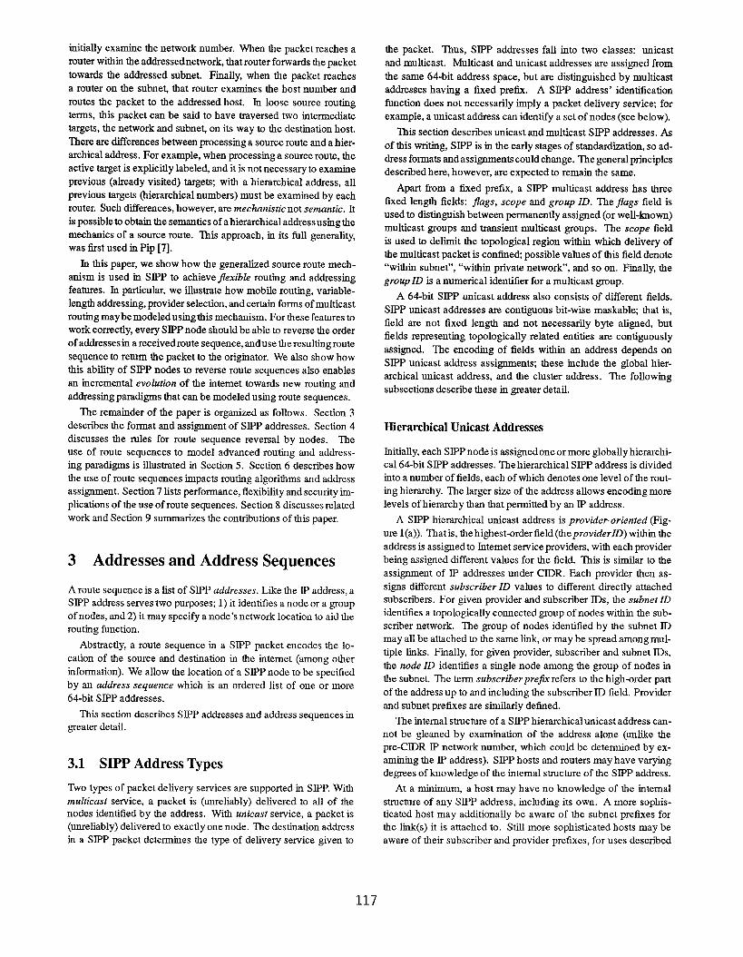
Assume now that 64-bits are no longer sufficient to form a globally
routable address for nodes H and 1. Suppose instead that two 64-bit
addresses suffice for this purpose. Then, nodes H and I are each
represented by two address sequences (F@re 5). We denote H‘saddress sequences as (P.D, S.H) and (Q.D, S.H). The S inthe lower-order address is a subnet within domain D. Strniiarly,
1’s address sequences are (Q.E, S.1) and (R.E, S.1). The lower
order address in each address sequence must be a globally unique
identifying address for the node.
PrOvldm P
m-nomm”’cJL@*tie *w’ W 0.0, “W .5/ Immnh$mue squwm s H, QD, Q.E, w
Revmedm!te aew31E4 S./, Q.E V.0, s.H
Figure 5: Extended Address: When 64-bits are not enough to
form a globally routable address, tbe locations of nodes H and
1 are completely specified by address sequences with two 64-bit
addresses each. This example shows how route sequences are
formed with extended addresses.
As before, H learns 1’s address sequences from DNS and forms
the following route sequence to send a packet to 1:
(S.H, Q.D, *Q.E, S. I).
The active target Q. E causes the packet to be rotned to domain E,
where the active target is advanced to:
(S.H, Q.D, Q.E, *S.1)
and delivered to I.
1 applies the reversal t-ales to the rncoming route sequence.
(Q.E, S.1) matches the tail of the route sequence, so 1 extracts
the unmatched portion and reverses it to get (Q.D, S.H). It
prepends the matched address sequence (this also happens to be
source-capable) and forms the following outgoing route sequence
(S.1, Q.E, *Q.D, S.H)
to reply to H
5.2 Multicast with Route Sequences
This section describes how the source route mechanism can be
used to accomplish multicast. We describe two kinds of multicasu
traditional multicast [3] and core-based tree (CBT) multicast. A
node’s notion of multicast addressing is extended so that a “multicast
address”is seen as an address sequencerather than a single multicast
address as is the case with IP. As with unicas~ SIPP multicast address
sequences are described using a series of 64-bit address elements.
The tinal element of the multicast address sequence is always the
SIPP multicast address.
When anode N joins a multicast group, it appends the multicast
address sequence to Q (Section 4.2). The address sequence formed
depends on the type of mttkicast routing used. A multicast address
sequence is not source-capable.
Traditional Mtdticast
In traditional multicas~ a packet from a sender to a multicast group
is sent on the shortest-path delivery tree (rooted at the sender) to
121

members of the group. The multicast address for traditional multi-
cast contains only one element—the SIPP multicast address for the
group.
Suppose we consider the extended address case shown in Fig-
ure 5. Assume that H is transmitting a traditional multicast with
multicast address M, and that 1 is a member of group M. Thus,
(M) is a valid address sequence for 1. H attaches the route se-
quence (S.H, Q.D, *M) to the multicast packet.
The active target in this route sequence is the SIPP multicast
address representing the group. Intermediate routers forward the
packet to all members of the group including 1. Each member
receives the packet with the route sequence unchanged.
If 1 wishes to respond mticast to H, it executes the reversing
rules (Section 4.3) in tlte following way. The address sequence
(M) matches the tail of the received route sequence best. 1 re-
verses the unmatched part to get (Q. D, S.If). Since a multicast
address cannotbeused as a source address (that is, multicast address
sequences are not source-capable), 1 knows to prepend one of its
tmicast address sequences to the route sequence, producing
(S.1, Q.E, +Q.D, S.H).
Core-based ‘Ikee Mtdticast
In core-based tree multicas; multicast packets are routed to their
destinations in two phases [2]. In the first phase, a packet from a
sender to a multicast group is unicast towards a core router. The
delivery tree for the multicast group is rooted at this router. The core
router initiates the second phase of CBT multicast it multicasts the
packet to the group members along the delivery tree. Thus, a core-
based tree multicast address sequence contains multiple addresses—
one or more unicast addresses to encode the address sequence for
the core router, and one SIPP multicast address.
Suppose we consider the simple address example shown in Fig-
ure 4. Assume that H is transmitting a core-based tree multicast
with multicast address M, that C is the unicast address for core
router for the group M, and that 1 is a member of group M. There-
fore, (C, M) is a valid address sequence for node 1. To initiate the
first phase of the multicas~ H forms the following route sequence:
(P.D.H, *C, M).
This packet is routed on the unicast address C until it reaches the
core router. This router advances the active targe~ to get the route
sequence
(P.D.H, C, *M).
This causes the packet to be multicast along the delivery tree for Mtowards each member of M.
Each group member (including 1) receives the packet with the
aboye route sequence. To generate a (unicast) reply, 1 fottows the
reversing rules described in Section 4.3. The address sequence,
(C, M) matches the tail of the incoming route sequence best.
1 reverses tbe unmatched portion and prepends a source-capable
address sequence to get (Q. E.1, P. D. H).
5.3 Host Mobility with Route Sequences
This section shows how route sequences can be used for mobile
communication. FirsL we introduce some terminology. A mobile
how is a node that is able to maintain its network comtections even
after being physically moved. A correspondent host is a node that
has a network comection open to a mobile host. A correspondent
host may itself be mobile. The foreign agersf is the SIPP router
to which the mobile host is attached after it moves. Finally, the
home agent is a SIPP node that is aware of the mobile host’s active
location. Each mobile host has a preconfiguredhome agent.
In our example, assume that H is a mobile host and that 1 is
its correspondent hose both with the (extended) address sequences
shown in Figure 5. Initially, a unicast packet from 1 to H carries
the route sequence
(S.1, Q.E, *Q.D, S.H).
Now suppose H moves to the vicinity of a foreign agent with
a cluster address B.O. H dkcovers the foreign agent’s cluster
address through periodic router advertisements (similar to an IS
hello advertisement in ES-IS [1 l]). H also periodically advertises
its addresses (similar to the ES hello advertisement in ES-IS). This
latter advertisement contains H‘s identifying address.
Then, tbrougb a mechanism beyond the scope of this paper, Hinforms its home agent of its new foreign agent. Packets carrying
the old route sequence from 1 are intercepted by the home agent.
The home agent forwards these packets to the foreign agen~ which
forwarda them to H.
After the H has discovered B.0, it alters the route sequence on
all outgoing packets to:
(S.H, B.0, *Q.E, S.I).
It is sufficient to include only H‘s identifying address in the route
sequenc~ we assume that the foreign agent is within H‘s identifying
address’s (S. H) routing scope. When 1 reverses the incoming route
sequence from H, it forms the following route sequence:
(S.1, Q.E, *B.0, S.H).
This causes packets to H to be routed through the foreign agent.
6 Implications of Address Sequences
Representing the location of a node by a sequence of 64-bit ad-
dresses impacts unicast address assignmen~ routing protocols, and
router performance. ‘his section dkcusses these implications in
greater detail.
6.1 Impact on Unicast Address Assignment
Like SIPP addresses, an address sequence is structured into a num-
ber of fields. The bit position of the field boundaries is not con-strained to be byte-aligned. However, the use of the source routing
mechanism for extending SIPP unicast addresses places two restric-
tions on the assignment of mticast addresses.
First since the source route mechanism requires a router to make
a forwarding decision based on 64-bit chunks, a field in an address
sequence cannot straddle a 64-bit boundary.
Second, when a multi-element address sequence is used to rep-
resent a node’s extended address, the lowest-order address must be
globally unique for uniquely identifying the node, and the highest-
order address must be globally unique so that packets can always
122

be delivered successfully to the top of the hierarchy. The other
addresses need not be globally unique (because, by carefully con-
figuring routing, it is possible to parse those addresses in the correct
context).
6.2 Router Handling of Extended Addresses
SIPP routing algorithms are identical to those used with the CIDR
version of IP, except that the 32-bit IP addresses are replaced with
64-bit SIPP addresses. ‘his is true even when extended addresses
are in use. This is possible because a SIPP unicast forwarding table
lookup is made by looking at only a single (64-bit) SIPP address.
The result of such a forwarding table lookup maybe to advance the
route header, causing the router to look at the following address in
the route sequence. This latter routing table lookup, however, is
made without consideration of the previous lookup.
Because the forwarding table lookup only involves a single ad-
dress, the routing algontltm only need carry a single address. If
extended addresses are used, however, care must be taken in the
distribution of routing information. In particular, routing infor-
mation cannot be leaked across routing hierarchy boundaries that
coincide witlr the boundary between two SIPP addresses in an ex-
tended address. For instance, consider the case where the subscriber
prefix is encoded in the upper address of a two-element extended
address, and the subnet and host parts are encoded in the lower
address. Because the subnet part is not globally unique, if the lower
address were advefised outside of tbe subscriber network, routing
in outside networks could fail. This faihtre mode does not exist in
traditional intemet protocols such as W and CLNP ([12]), where
the entire destination address is examined by every router. If rout-
ing protocols in SIPP advertise complete extended addresses, then
this failure condition can be detected, though not corrected without
manual router configuration.
Finally, for extended addresses to work with single-address rout-
ing algorithms, routers must recognize addresses that identify them-
selves, and advance the routing header upon receiving such an ad-
dress. The high-order part of a router’s extended address is among
the addresses that a router identifies as its own for the purpose of
advancing the routing header.
6.3 Processing Source Address Sequences
For certain types of multicastrouting-namely those based on build-
ing multicast trees from the source—it is necessary for a router toexamine the source address as well as the destination (multicast)
address when forwarding a packet. Since a SIPP source may be
represented by an address sequence (e.g., a mobile address sequence
or an extended address), the router must examine the source address
sequence in such situations.
All of the addresses of the source address sequence (except for
the identifying address) are in the routing header. To make its
forwarding decision, the router examines one or more addresses
immediately preceding the active target. These are the addresses
in the SIPP Routing Header immediately preceding the address
indicated by the nexr address field, upto and including the address
in the source address field. We call this behavior “peek-behind”.
7 Possible SIPP Enhancements
The use of route sequencesin SIPP also hnpactshost and router per-
formance, flexibility in modeling dflerent routing and addressing
paradigms, and security. This section discusses solutions for these
problems.
7.1 Using SIPP Flow Labels To Improve Per-
formance
The SIPP Jow lubel (Figure 2) maybe used by senders to label
packets which require special handling (e.g. “real-time” service)
by SIPP routers. The flow label field consists of two sub-fields,
one of which is the flow ID field (for a more detailed description
of the SIPP flow label, see [5]). Packets from the same source
and carrying the same (non-zero) flow ID are associated with the
same special handling state established (by mechanisms which are
beyond the scope of this paper) in routers on the path from source
to destination.
SIPP hosts may exhibit poor performance because they need to
apply the route sequence reversal rules on every incoming packet
(Section 4.3). SIPP nodes can use the following property of flow
Ills to improve performance if a source assigns a non-zero flow
lD to outgoing packets, then, when the outgoing route sequence
changes, the source must assign anew flow ID on outgoing packets.
Receivers can cache the flow ID on the last packet to have arrived
from a sendeq receivers reverse incoming route sequence only when
the incoming packet’s flow ID is different from the cached value or
when the flow ID is zero.
The above property of flow ID can be used to improve router
performance as well. In each packe; the source address and a non-
zero flow ID uniquely determines the next hop router and outgoing
interface(s) at each router on the patlt of the packet. Routers can
cache this mapping to speed up packet forwarding. This is par-
ticularly useful for forwarding decisions where “peek-behind” is
necessary (Section 6.3).
7.2 Peek Ahead
In SIPP, all unicast forwarding decisions are made by looking at
a single 64-bit address only. As a consequence, some other for-
warding decisions may require “peek-behind”. It is instructive to
consider what happens if “peek-ahead’’(the ability of routers to look
beyond the active target of a route sequence without advancing the
active target) is allowed. This feature results in a more expensive
forwarding algorithm, but has some advantages.
One advantage is that the restrictions in distribution of routing
information and address assignment (Section 6.1 ) are eliminated.
Another advantage is the increased flexibility in modelig CBT
multicast. In the example of Section 5, the packet travels all tie way
to the core of the multicast tree before starting the second, mtskicast
phase of its transmission. If peek-ahead is allowed, then routers
on any of the trees of the core could peek-ahead to the multicast
address and determine if they are on the tree for that particular
multicast group. If they are, then they could immediately initiate
the multicast phase of the transmission, resulting in lower latency
for the transmission.
Also, with peek-ahead, peek-behind is no longer necessary. This
123

is accomplished by replicating the source address sequence in the
route sequence after the multicast address. If the active target in
a packet were a muhicast address! routers WOUld peek-ahead toexamine the source address without advanciugtbe active address of
the route sequence.
In summary, with peek-ahead, forwarding cart be accomplished
with one mechanism (source routing with peek-ahead) rather than
with two (source routing without peek-ahead plus source routing
with peek-behind). This allows for a cleaner implementation over-
all.
7.3 Partial Route Sequence Reversal
The route sequence reversal rules described in Section 4.3 can, in
some cases, lead to non-optimal, undesirable, or even incorrect
behavior. An example of non-optimal behavior is the provider
selection example of Section 5.1, where the reversed cluster address
is redundant. An example of undesirable behavior is a policy route,
when the desired policy in. reverse direction is dflerent from that in
the forward direction.
An example of incorrect behavior is a node-level source route,
where the nodes have extended addresses. For example, con-
sider the case where the source route in the forward direction is
(... Ah, Al, Bh, B,, C,, Cl,...), where A, B, and Care tar-
get nodes in the source route, and the subscripts h and/ denote the
high- and low-order parts of the address sequence. When this source
route is reversed, producing (. . . G!, Ctt, B/, Bh, Al, Ah, . . .)the low-order part of each extended address precedes the high-order
part. This will not work in general, because a packet must tirst
be routed to the high-order address before it can be routed to a
low-order address.
In all of the above examples, the problem arises when the the route
sequence contains more than the minimum information necessary
to retom the packet to the source (that is, more thanjost tie source’s
and destination’s address sequence). One solution is to include a
field in the Routing Header that indicates the length of tie sender’s
address sequence. By defaul~ a receiver discards all addresses in
the route sequence that are not part of its own address sequence and
not in the sender’s address sequence.
7.4 Security
With SIPP, a host automatically reverses the route sequence of any
received packet for the purpose of forming the route sequence for the
return packet. This opens SIPPhosts to the following eavesdropping
attack.
Assume that SIPP hosts X and Y, with addresses A and Brespectively, are exchanging packets with route sequences (A, B)in the direction from X to Y and (B, A) in the opposite direction.
Now, assume that a SIPP host P with address C that is not otherwise
on the path between X and Y wishes to receive the packets of
the exchange. Node P sends a packet to Y with route sequence
(A, C, B). Y will reverse the new route sequence, and send return
packets with route sequence (B, C, A). This will cause all packets
between X and Y to be routed through P.
There a number of ways to defend against this particular attack.
The strongest defense is to use the optional SIPP Authentication
Header [1]. This contains the sender’s digital si~ature, making it
difficult for the eavesdropper to modify the route sequence unde-
tected. A simpler but weaker defense is to use the flow ID enhance-
ment described in Section 7.1, and to add an optional header that
allows a host to indicate what the previous flow lD was when it
modities the routing header. Flow IDs are pseudo-random [5], and
since the eavesdropper is not generally able to observe packets from
the hosts it wants to eavesdrop on, it is difficult for the eavesdropper
to guess the current flow ID. Finally, a receiver can learn (from a
trusted third party) the extended address of the sender, and refuse to
include any addresses in the route sequence other than source and
destination addresses.
8 Related Work
Other work has proposed the use of source routing to achieve one
or more of the features described in Section 5. For instance, both
Inter-Domain Policy Routing [21] and Source Demand Routing [6]
use source routing to encode specialized policy routes. Similarly,
[20] describes the use of source routing to solve the host mobility
problem. SIPP’S route sequence mechanism generalizes these uses
of source routing to dfierent routing and addressing paradigms.
Other existing network protocols, such as CLNP (Cotmection-
Less Network Protocol, [12]) and IP have loose source routing
mechanisms. Unlike SIPP, however, CLNP and W nodes are not re-
quired to correctly reverse loose source routes (route sequences) or
recognize that packet sources and destinations may be represented
as address sequences.
Finally, other mechanisms may be defined for achieving one or
more of the advanced routing and addressing features enabled by
SIPP’S used of generalized source routing. For instance, the CLNP
packetheader allows variable length node addresses. Encapsulation
[16] canbeusedto emulate provider selection [19] and mobility [14]
in IP.
However, we believe that the SIPP approach of having a single
framework for providing advancedrouting andaddressingfonctions
is more desirable than the other protocols’ approach of having mul-
tiple different mechanisms for different fonctions. A single mecha-
nism is more efficient than having multiple mechanisms. Separate
mechanisms require separate checks and actions, one for each mech-
anism, a single mechanism, provided that it is itself efficient (which
is the case with SIPP’S source route mechanism), allows checking
for and accomplishing multiple functions to be done with one action.
A single powerful mechanism installed in all systems also allows
easier evolution to a new routing and addressing function, if that
new fonction can be implemented with the single mechanism. Since
the loose source route mechanism of SIPP is general in nature (as
evidenced by the number of different fonctions it can support), we
expect that it will support a wide variety of new functions.
9 Summary
liI this paper, we describe the methods used to achieve advanced
routing and addressing functions in SIPP, a proposed replacement
for II? Our basic approach generalizes IP’s loose source route mech-
anism, we show how a number of routing and addressing paradigms
can be modeled as routing to a series of intermediate destinations
on the patlt to the final destination.
In SLPP, the addresses representing these intermediate destina-
124

tions can be one of the multicast address, the hierarchical unicast
address, and the cluster address. The multicast and hierarchical
unicast addresses are analogous to those of IP, except they are 64
bita in length. The cluster address is used to send a packet to one
of a number of SIPP nodes in a hierarchical cluster of nodes, and is
useful for, among other things, provider selection.
To use loose source routing for advanced routing and addressing,
two functions are required of SIPP nodes. FmL SIPP nodes must
be able to view their own address as a sequence of 64-bit addresses,
Second, they must be able to reverse the loose source route in a
received packet for use in return packets. We illustrate tha~ if
nodes perform these functions correctly, loose source routing can
be used to achieve mobility, extended (variable-length) addressing,
provider selection, and source-based and core-based multicast.
We argue that having a single powerful mechanism to achieve
a wide range of routing and addressing functions is preferable to
having multiple specitic mechanisms, one for each function. A
single mechanism is easier to implement and more efficient than
multiple mechanisms, and it makes future evolution easier.
Unfortunately, the use of route sequences has some undesirable
side-effects. For rnstartce, SIPP has a new failure mode resulting
from the fact that routers do not necessarily need to examine the
high-order part of an extended address to forward a packet. SIPP is
also prey to an eavesdropping attack that does not exist with II? We
discuss techniques for overcoming some of these shortcomings.
Acknowledgements
Steve Deering, the inventor of SJP, is responsible for many of tie
original ideas described in this paper, as well as much of tbe ter-
minology. Bob Gilligan, Bob Hinden, Christian Huitema and Erik
Nordmark also contributed to the desi~ of SIPP routing and ad-
dressing. Finally, Susan Thomson, Andrew Heybey, and the anony-
mous referees provided insightfirl comments on earlier versions of
this paper.
References
[1]
[2]
[3]
[4]
[5]
[6]
R. Atkinson. SIPP Authentication
work in progress, available via
ds.intemic.ne~ April 1994.
Header. Mcmet Draft
anonymous FTP from
A. Ballardle, P. Francis, and J. Crowcroft. An Architecture for
Scalable Inter-Domain Multicast Routing. ACM SIGCOMM
Symposium on Communication Architectures and Protocol-s,
pages 85-95, September 1993.
S. Deering. Multicast Routing in Intemetworks and Extended
LANs. ACM SIGCOMM Symposium on Communication Ar-
chitectures and Protocols, August 1988.
S. Deering. SJR A Simple Intemet Protocol. IEEE Network,
7(6): 16-28, May 1993.
S. Deering. Simple Intemet Protocol Plus (SIPP) Specifica-
tion. Intemet llraf~ work in progress, available via anonymous
FTP from ds.intemicme~ February 1994.
D. Estrin, S. Hotz, and Y. Rekhter. A Unified Approach to
Inter-Domain Routing. Request for Comments 1322, DDN
Network hformation Center, May 1992.
[7]
[8]
[91
[10]
[11]
[12]
[13]
[14]
[15]
[16]
[17]
[18]
[19]
[20]
[21]
P. Francis. A Near-term Architecture for Deploying Pip. IEEE
Network, 7(6)30-37, May 1993.
P. Francis. Advanced Routing and Addressing using Gener-
alized Source Routing. Submitted to the Journal of Internet-
working, 1994.
V, Fuller, T. Li, J. Yu, and K. Varadhan. Classless Inter-
domain Routing (CIDR) an Address Assignment and Aggre-
gation Strategy. Request For Comments 1519, DDN Network
Information Center, September 1993.
P. Gross and P. Ahnquist. IESG Deliberations on Routing and
Addressing. Request For Comments 1380, DDN Network
Information Center, November 1992.
International Organization for Standardmation. End Sys-
tem to Intermediate System routeing exchange protocol for
use in conjunction with the Protocol for providing the
connectwnless-mode network service (ISO 8473), 1S0 9542,
1988.
International Organization for Standa.rdkation. Protocol for
Providing Connectionless-mode Network Service, 1S0 8473,
1988.
J. Iormnidis. Source Routing Experiments. IIYfF Mobile-IP
Working Group maiLittg lis~ July 1992.
J. Ioatmidis, D. Duchamp, and G. Q. Maguire. IP-based Pro-
tocols for Mobile httemetworkiug, Proceedings of 1991 ACM
Sigcomm Symposium on Communication Architectures and
ProtocoZs, September 1991.
D. Katz and P. S. Ford. TUBA Replacing IP with CLNP,
IEEE Network, 7(6)38-47, May 1993.
D. Mills and R. Woodbum. A Scheme for an Itttemet Encap-
sulation Protocol Version 1. Request for Comments 1241,
DDN Network Information Center, July 1991.
P. Mockapetris. Domain Names - Concepts and Facilities, Re-
quest For Comments 1035, DDN Network Information Center,
November 1987.
J. Postel. IntemetProtocol. RequestFor Comments 791, DDN
Network Information Center, September 1981.
Y. Rekhter. Selecting a Direct Provider. Jntemet Draft work in
progress, available via anonymous FTP from ds.intemic.ne~
April 1994.
Y. Rekhter and C. Perkins. Loose Source Routing for Mo-
bile Hosts. Intemet Draft, work in progress, available via
anonymous FTP from ds.intemic.ne~ February 1994.
M. Steenstmp. An Architecture for Inter-Domain Policy Rout-
ing. Request for Comments 1477, DDN Network Information
Center, July 1993.
125