Embed Size (px)
Citation preview
Journal of Electroanalytical Chemistry 683 (2012) 70–74
Contents lists available at SciVerse ScienceDirect
Journal of Electroanalytical Chemistry
journal homepage: www.elsevier .com/locate / je lechem
Flexible metal-free counter electrode for dye solar cells based on conductivepolymer and carbon nanotubes
Kerttu Aitola a,⇑, Maryam Borghei a, Antti Kaskela a, Erno Kemppainen a, Albert G. Nasibulin a,Esko I. Kauppinen a, Peter D. Lund a, Virginia Ruiz a,b,⇑, Janne Halme a,⇑a Department of Applied Physics, Aalto University School of Science, P.O. Box 15100, 00076 Aalto, Finlandb CIDETEC-IK4, Centre for Electrochemical Technologies, Paseo Miramón 196, E-20009 Donostia-San Sebastián, Spain
a r t i c l e i n f o
Article history:Received 20 January 2012Received in revised form 25 June 2012Accepted 4 August 2012Available online 14 August 2012
Keywords:Dye solar cellCarbon nanotubeConductive polymerPlasticCounter electrodeCatalytic
1572-6657/$ - see front matter � 2012 Elsevier B.V. Ahttp://dx.doi.org/10.1016/j.jelechem.2012.08.006
⇑ Corresponding authors. Address: Department of Asity School of Science, P.O. Box 15100, 00076 Aalto,Halme). Tel.: +8615140370273 (K. Aitola).
E-mail addresses: [email protected] (K. Aitola), [email protected] (J. Halme).
a b s t r a c t
The counter electrodes (CEs) for flexible dye solar cells (DSCs) are normally prepared by sputtering plat-inum on indium tin oxide (ITO) plastic substrate. However both ITO and platinum are expensive materialsthat need to be replaced with cheaper alternatives in large scale production of low-cost DSCs. We fabri-cated a flexible and completely carbon-based CE for DSCs based on electropolymerized poly (3,4-ethyl-enedioxythiophene) (PEDOT) on single-walled carbon nanotube (SWCNT) film on a plain plasticsubstrate. The DSCs with such a CE had an efficiency of 4.0%, which is similar to the efficiency of the ref-erence DSCs (3.9%) based on conventional sputtered platinum on ITO-plastic CE. The carbon-based elec-trode was prepared by a simple press-transfer method of SWCNTs from the collection filter used in thegas phase synthesis and by electrochemical deposition of PEDOT on it. Electrochemical impedance spec-troscopy confirmed that the PEDOT–SWCNT film had the best catalytic performance among the studiedCE materials, and the film was also slightly transparent. The results demonstrate a successful combina-tion of the conductive and catalytic properties of SWCNTs and PEDOT, respectively.
� 2012 Elsevier B.V. All rights reserved.
1. Introduction
The dye solar cell [1] is one of the possible options for large-scale roll-to-roll production of photovoltaic cells on flexible plasticand metal substrates. The conventional choice for a plastic DSCcounter electrode has been sputtered platinum on indium tinoxide–polyethylene terephthalate (ITO–PET) or ITO–polyethylenenaphthalate substrates. Sputtering has been the method of Ptdeposition, since plastic substrates do not withstand the high tem-peratures of thermal Pt deposition used with glass substrates.However, Pt and In are expensive and rare metals, and ITO is sub-jected to cracking when bent [2].
One candidate for the conductive, catalytic and flexible DSC CEmaterial is the randomly oriented single-walled carbon nanotubenetwork [3–5]. The SWCNT network films are highly flexible [6]and can be deposited on a desired substrate by a simple press-transfer method [7]. When such a film is applied as a DSC CE, theSWCNTs may simultaneously carry out the conductive and the cat-alytic functions of the CE. However, this type of CE, which, from the
ll rights reserved.
pplied Physics, Aalto Univer-Finland (K. Aitola, V. Ruiz, J.
[email protected] (V. Ruiz),
point-of-view of manufacturing and flexibility, is preferentiallyapplied as a thin, semi-transparent layer, is as such only moder-ately catalytically active toward the tri-iodide reduction reactionof the DSC CE [5].
Conductive polymers, such as poly-(3,4-ethylenedioxythio-phene) (PEDOT), its poly (styrenesulfonate) (PSS) and p-toluene-sulfonate doped version, and polyaniline, are promising organicDSC catalysts. These materials have been successfully applied asthe DSC CE on glass [8–10] and plastic [11] substrates, but alwaysin parallel with the conventional transparent conductive layers(ITO or fluorine-doped tin oxide, FTO). PEDOT–carbon nanotube[12–14], PEDOT:PSS–carbon black [15] and PEDOT–graphene [16]composites have also been used on FTO or ITO glass. Only in onestudy, a PEDOT:PSS film on a polyester substrate was studied asthe sole CE structure, but the DSCs had a modest 0.05% efficiency[17].
In this work, we combine the best properties of electrochemi-cally deposited PEDOT and the aforementioned random networkSWCNT films and demonstrate a composite counter electrode forflexible DSCs without additional conductive or catalytic layers.The catalytic performance of the resulting PEDOT–SWCNT CE wasfound superior to the sputtered platinum on ITO–PET and ther-mally deposited platinum on FTO glass. The catalytic activities ofthe films were studied with cyclic voltammetry (CV) in an electro-chemical 3-electrode cell and with electrochemical impedance
K. Aitola et al. / Journal of Electroanalytical Chemistry 683 (2012) 70–74 71
spectroscopy (EIS) in the DSC, and the conductivities and opticalproperties were addressed.
The method of choice for coating the SWCNTs with PEDOT wasoxidative electropolymerization of EDOT. This method offersseveral advantages over other approaches, such as spin-coating:it enables precise control of the amount (thickness) of the polymer,it is fast (in the tens of seconds scale), yet very reproducible, it canbe upscaled to large electrode areas and it is carried out at roomtemperature. In electrodeposition, the underlying SWCNT networkprovides a conducting, porous platform on which the PEDOT nucle-ation and coating occurs, maximizing the PEDOT–SWCNT filminterfacial area. Thus, the SWCNT network acts as a templateduring the electropolymerization, leading to porous, wire-likenanostructures with PEDOT wrapping the SWCNT bundles [18].
In this paper, we show that the performance of SWCNT networkelectrodes on PET plastic as the DSC CE can be significantly im-proved by electrodepositing PEDOT on them. The result demon-strates a Pt and In free CE alternative for flexible DSCs withperformance comparable to sputtered Pt on ITO–PET.
Table 1Electro-optical properties of the various counter electrode materials studied. EC refersto ‘‘electrochemically’’ and T is optical transmittance.
CE type RSH (X/sq) T at 550 nm (%)
Ethanol densified SWCNT network 13.6 ± 0.4 9 ± 1EC cleaned SWCNT network 11.8 ± 0.4 10 ± 1EC cleaned SWCNT with 33.7 mC/cm2 PEDOT 12.2 ± 0.4 5 ± 1ITO–PET 54 ± 2 89 ± 1ITO–PET-Pt 23 ± 0.7 21 ± 1
2. Experimental
The SWCNTs used in this study were synthesized by an aerosolCVD process [19], described in detail in the Supporting Informa-tion. The SWCNTs are grown and subsequently form small diame-ter bundles in the gas phase, and the bundles are collecteddownstream at the outlet of the synthesis reactor by membrane fil-tration, and the thus formed SWCNT network can be transferred toseveral substrate materials by a simple room temperature press-transfer process [7]. Here the SWCNT networks were transferredto PET plastic substrates (Goodfellow, Bi-Axially oriented PET) afterthe SWCNT network was mechanically cut down to the DSC CEdimensions. The SWCNT networks were ethanol densified afterthe transfer to improve adhesion of the network to the substrate[7,20].
The SWCNT films were electrochemically purified of iron cata-lyst particles present in the films from the SWCNT synthesis byanodic stripping in 1 M HNO3 in an aqueous solution [21] priorto the PEDOT deposition, since iron is known to be detrimentalfor the DSC photoelectrode (PE) [5]. The method is known to beeffective for iron removal from the SWCNT films and non-harmfulto the film quality [21]. Electropolymerization of 3,4-ethylenedi-oxythiophene (EDOT) was conducted on the iron-purified SWCNTfilms by chronocoulometry, at +1.0 V, in an aqueous solution of3 mM EDOT and 0.3 M LiClO4. PEDOT films of different thicknesswere produced by varying the deposition time until reaching dif-ferent final deposition charge values, ranging from around 7 to70 s and from 10 to 100 mC/cm2, respectively.
In order to select the optimal PEDOT–SWCNT CE, the electrocat-alytic activity of the films with different PEDOT thicknesses (indi-cated by the total electrodeposition charge) was evaluated bycyclic voltammetry (CV) in an acetonitrile solution containing1 mM I2, 10 mM LiI and 0.1 M LiClO4. It was observed, that thor-ough rinsing and conditioning of the PEDOT–SWCNT CEs is re-quired for enhanced DSC performance and stability. We alsocarried out potential cycling of the films in the electrolyte solutionto promote releasing of occluded monomers (EDOT) and oligomersfrom the PEDOT–SWCNT network (see Supporting Information). Toensure further removal of unbound monomer and polymer, thePEDOT–SWCNT films were rinsed with acetonitrile and deionisedwater and dried with nitrogen flow. Furthermore, prior to theDSC assembly, the PEDOT–SWCNT CEs were conditioned by soak-ing them overnight in the same electrolyte solution as used inthe DSC, and finally rinsed with ethanol and dried.
The solar cells were prepared with the photoelectrode on FTOglass substrate and varying CEs: SWCNT film on PET, PEDOT–SWCNT on PET, sputtered Pt on ITO–PET and thermally depositedPt on FTO glass (see Supporting Information). The PEs were manu-factured by doctor-blading titania paste (Dyesol DSL 18NR-T, aver-age particle diameter 20 nm) on FTO-coated glass with a sheetresistance of 15 X/sq (TEC 15, Pilkington, Hartford Glass Company,Inc.) and sintering in air in 450 �C for 30 min, to reach TiO2 films ofaround 15 lm thickness and 5 mm � 8 mm geometric area. ThePEs were dyed in N719 dye (Dyesol) in ethanol bath for about 17 h.
The counter electrodes (apart from the thermally platinized FTOglass CEs) were characterized by a multimodal approach, includingelectrical sheet resistance measurements, optical absorption spec-troscopy, field emission scanning electron microscopy (SEM) andenergy dispersive X-ray spectroscopy (EDX). The photovoltaiccharacterization of the solar cells was carried out in a solar simu-lator providing a 1 Sun equivalent light intensity. The EIS measure-ment was carried out in the frequency range 100 kHz to 100 mHz,using 10 mV amplitude, starting from the high-frequency end andsweeping to the low frequencies and back. The measurement wastaken in the dark and by polarizing the cells in the voltage range 0to �0.9 V for all the other cells except the SWCNT cells, for whichthe voltages were 0 to �1.1 V, to obtain similar cell current densi-ties. (All measurement details are listed in the SupportingInformation.).
3. Results and discussion
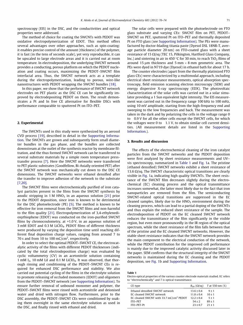
The effects of the electrochemical cleaning of the iron catalystparticles from the SWCNT networks and the PEDOT depositionwere first analyzed by sheet resistance measurements and UV–vis spectroscopy, summarized in Table 1 and Fig. 1a. The pristine(ethanol densified) SWCNT networks exhibit a sheet resistance of13.6 X/sq. The SWCNT characteristic optical transitions are clearlyvisible in Fig. 1a, indicating high quality SWCNTs. The sheet resis-tance of the SWCNT film decreases slightly during the electro-chemical (EC) cleaning process and the optical transmittanceincreases somewhat, the latter most likely due to the fact that ironnanoparticles are removed from the film. The semiconductingSWCNT-related optical transitions are suppressed in the ECcleaned samples, likely due to the HNO3 environment during thecleaning process, which can lead to a partial doping of the SWCNTsand thus explain the reduced sheet resistance of the sample. Theelectrodeposition of PEDOT on the EC cleaned SWCNT networkreduces the transmittance of the film significantly in the visibleregion, but even more pronouncedly in the IR region of the opticalspectrum, while the sheet resistance of the film falls between thatof the pristine and the EC cleaned SWCNT networks. However, thestable sheet resistance indicates that the SWCNT network providesthe main component to the electrical conduction of the network,while the PEDOT contribution for the improved cell performanceis mainly due to the improved catalytic activity discussed later inthe paper. SEM confirms that the structural integrity of the SWCNTnetworks is maintained during the EC cleaning and the PEDOTdeposition, see Fig. 1b and Supporting Information.

0.1 0.2 0.3 0.4 0.5 0.60
2
4
6
8
10
12
14
V (V)
therm. Pt on FTO glassPEDOT−SWCNT on PETsputt. Pt on ITO−PETSWCNT on PET
i (m
A/c
m2 )
Fig. 3. The IV curves of the example DSCs with different counter electrodes:PEDOT–SWCNT film on PET substrate, SWCNT on PET, sputtered platinum on ITO–PET and thermally deposited platinum on FTO glass.
Table 2Average photovoltaic parameters of the studied cell types.
CE type No. of cells iSC (mA/cm2) VOC (V) F.F. (%) g (%)
PEDOT–SWCNT 6 11 ± 0.4 0.58 ± 0.01 63 ± 2 4.0 ± 0.1SWCNT 4 12 ± 0.2 0.61 ± 0.01 28 ± 1 2.0 ± 0.1Sputtered Pt-ITO–PET 4 14 ± 0.5 0.59 ± 0.01 46 ± 2 3.9 ± 0.2Thermal Pt-FTO glass 4 13 ± 0.6 0.59 ± 0.01 58 ± 1 4.3 ± 0.2
(a) (b)
Fig. 1. (a) Optical transmittance of the SWCNT-based counter electrode materials and the sputtered Pt on ITO–PET. The sputtered Pt on ITO–PET has relatively lowtransmittance because of the thick, mirror-like Pt layer. (b) SEM image of the PEDOT–SWCNT film.
Fig. 2. Cyclic voltammograms of the bare SWCNT (as-grown and electrochemicallypurified), PEDOT-coated SWCNT (deposition charges 17 and 34 mC/cm2), bare ITOand PEDOT-coated (17 mC/cm2) ITO electrodes in acetonitrile solutions with 1 mMI2, 10 mM LiI and 0.1 M LiClO4. Scan rate 0.1 V/s.
72 K. Aitola et al. / Journal of Electroanalytical Chemistry 683 (2012) 70–74
Fig. 2 shows cyclic voltammograms for the SWCNT, PEDOT–SWCNT, bare ITO and PEDOT on ITO electrodes (the latter notstudied here in the DSC). The CVs for the PEDOT–SWCNT filmsexhibit two distinct pairs of redox peaks, Iox and Ired, attributedto the oxidation and reduction of I�3 =I�, and IIox and IIred to theoxidation and reduction of I2=I�3 [22]. The PEDOT–SWCNT CV con-trasts with the poorer catalytic activity shown by the bareSWCNT electrode, which exhibits much larger peak spacing forthe I�3 =I� redox couple (the peak spacing is inversely proportionalto the rate constant of the electrochemical reaction). The highercurrent densities together with the smaller peak spacing for theI�3 =I� redox reaction obtained for the PEDOT-coated SWCNTelectrodes compared to the uncoated SWCNTs are indicative ofan expected enhanced performance as DSC CE. However, neithercurrent density nor peak spacing is further improved by increas-ing the amount of deposited PEDOT beyond 30 mC/cm2 (seeSupporting Information).
The synergistic effect of the separate catalytic activities of PED-OT and SWCNTs is illustrated by comparing the CVs obtained forPEDOT–ITO and PEDOT–SWCNT (and for plain ITO). In the CV ofthe plain ITO electrode, the redox peaks are missing. For PEDOT–ITO, the two redox peak pairs are broader, located at larger overpo-tentials and are less reversible than for PEDOT–SWCNT, revealingthat the intrinsic catalytic properties of PEDOT alone are notresponsible for the improved response. This highlights the collabo-rative catalytic effect of the SWCNTs and PEDOT, meaning that the
SWCNT electrode is a better substrate for the PEDOT catalyst thanITO. This is expected due to the porous structure and the high sur-face area of the SWCNT network.
The current–voltage (IV) curves of all the studied DSC types areshown in Fig. 3 and the IV parameters in Table 2. The efficiencies ofthe PEDOT–SWCNT DSCs are 4.0%, compared to the 2.0% of theSWCNT-DSCs, and similar to those of the sputtered Pt-ITO–PETand thermal Pt-FTO glass DSCs. The good catalytic performanceof the PEDOT–SWCNT films is manifested in the good fill factorof the IV curves. For some reason the iSC values are slightly lowerfor the PEDOT–SWCNT cells than for the other cells, the reason ofwhich we discuss in the following sections.
(a) (b)
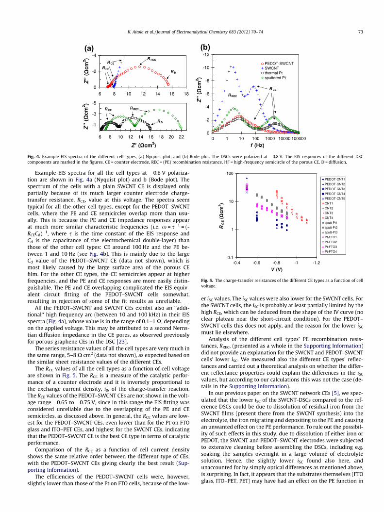
Fig. 4. Example EIS spectra of the different cell types, (a) Nyquist plot, and (b) Bode plot. The DSCs were polarized at �0.8 V. The EIS responces of the different DSCcomponents are marked in the figures, CE = counter electrode, REC = (PE) recombination resistance, HF = high-frequency semicircle of the porous CE, D = diffusion.
Fig. 5. The charge-transfer resistances of the different CE types as a function of cellvoltage.
K. Aitola et al. / Journal of Electroanalytical Chemistry 683 (2012) 70–74 73
Example EIS spectra for all the cell types at �0.8 V polariza-tion are shown in Fig. 4a (Nyquist plot) and b (Bode plot). Thespectrum of the cells with a plain SWCNT CE is displayed onlypartially because of its much larger counter electrode charge-transfer resistance, RCE, value at this voltage. The spectra seemtypical for all the other cell types, except for the PEDOT–SWCNTcells, where the PE and CE semicircles overlap more than usu-ally. This is because the PE and CE impedance responses appearat much more similar characteristic frequencies (i.e. x = s�1 = (-RCECd)�1, where s is the time constant of the EIS response andCd is the capacitance of the electrochemical double-layer) thanthose of the other cell types: CE around 100 Hz and the PE be-tween 1 and 10 Hz (see Fig. 4b). This is mainly due to the largeCd value of the PEDOT–SWCNT CE (data not shown), which ismost likely caused by the large surface area of the porous CEfilm. For the other CE types, the CE semicircles appear at higherfrequencies, and the PE and CE responses are more easily distin-guishable. The PE and CE overlapping complicated the EIS equiv-alent circuit fitting of the PEDOT–SWCNT cells somewhat,resulting in rejection of some of the fit results as unreliable.
All the PEDOT–SWCNT and SWCNT CEs exhibit also an ‘‘addi-tional‘‘ high frequency arc (between 10 and 100 kHz) in their EISspectra (Fig. 4a), whose value is in the range of 0.1–1 X, dependingon the applied voltage. This may be attributed to a second Nerns-tian diffusion impedance in the CE pores, as observed previouslyfor porous graphene CEs in the DSC [23].
The series resistance values of all the cell types are very much inthe same range, 5–8 X cm2 (data not shown), as expected based onthe similar sheet resistance values of the different CEs.
The RCE values of all the cell types as a function of cell voltageare shown in Fig. 5. The RCE is a measure of the catalytic perfor-mance of a counter electrode and it is inversely proportional tothe exchange current density, i0, of the charge-transfer reaction.The RCE values of the PEDOT–SWCNT CEs are not shown in the volt-age range �0.65 to �0.75 V, since in this range the EIS fitting wasconsidered unreliable due to the overlapping of the PE and CEsemicircles, as discussed above. In general, the RCE values are low-est for the PEDOT–SWCNT CEs, even lower than for the Pt on FTOglass and ITO–PET CEs, and highest for the SWCNT CEs, indicatingthat the PEDOT–SWCNT CE is the best CE type in terms of catalyticperformance.
Comparison of the RCE as a function of cell current densityshows the same relative order between the different type of CEs,with the PEDOT–SWCNT CEs giving clearly the best result (Sup-porting Information).
The efficiencies of the PEDOT–SWCNT cells were, however,slightly lower than those of the Pt on FTO cells, because of the low-
er iSC values. The iSC values were also lower for the SWCNT cells. Forthe SWCNT cells, the iSC is probably at least partially limited by thehigh RCE, which can be deduced from the shape of the IV curve (noclear plateau near the short-circuit condition). For the PEDOT–SWCNT cells this does not apply, and the reason for the lower iSC
must lie elsewhere.Analysis of the different cell types’ PE recombination resis-
tances, RREC, (presented as a whole in the Supporting Information)did not provide an explanation for the SWCNT and PEDOT–SWCNTcells’ lower iSC. We measured also the different CE types’ reflec-tances and carried out a theoretical analysis on whether the differ-ent reflectance properties could explain the differences in the iSC
values, but according to our calculations this was not the case (de-tails in the Supporting Information).
In our previous paper on the SWCNT network CEs [5], we spec-ulated that the lower iSC of the SWCNT-DSCs compared to the ref-erence DSCs could be due to dissolution of residual iron from theSWCNT films (present there from the SWCNT synthesis) into theelectrolyte, the iron migrating and depositing to the PE and causingan unwanted effect on the PE performance. To rule out the possibil-ity of such effects in this study, due to dissolution of either iron orPEDOT, the SWCNT and PEDOT–SWCNT electrodes were subjectedto extensive cleaning before assembling the DSCs, including e.g.soaking the samples overnight in a large volume of electrolytesolution. Hence, the slightly lower iSC found also here, andunaccounted for by simply optical differences as mentioned above,is surprising. In fact, it appears that the substrates themselves (FTOglass, ITO–PET, PET) may have had an effect on the PE function in
74 K. Aitola et al. / Journal of Electroanalytical Chemistry 683 (2012) 70–74
these cells, arising from for instance the different chemical compo-sition or water and electrolyte permeability of the substrates andtheir secondary effects on the PE performance. These observationscall for a more closer look on the effect of plastic substrates on theDSC performance, keeping also other possible degradation mecha-nisms in mind.
4. Conclusions
To replace the platinum catalyst and the transparent conductiveindium tin oxide layer of the DSC CE and to obtain flexibility, wefabricated a completely carbon-based counter electrode. AerosolCVD synthesized SWCNTs were transferred from the filter, towhich they were collected from the gas phase, to a PET plastic sub-strate and electrochemically covered with conductive PEDOT poly-mer. This allowed us to improve the catalytic activity of the SWCNTnetwork considerably, so that its performance as a DSC CE becamecomparable to sputtered platinum on an ITO–PET substrate. ThePEDOT–SWCNT CE has superior catalytic performance comparedto the other CE types studied here and its sheet resistance meetsthe requirement of the DSC function at full sun light intensities.
Acknowledgements
This study was carried out in the project MIDE/CNB-E. K. Aitolais grateful for the graduate school of Nordic Center of Excellence inPhotovoltaics for the scholarship. V. Ruiz gratefully acknowledgesthe Academy of Finland (Project 125504) and the Spanish Ministryof Science and Innovation (Prog. Ramon y Cajal). A. Nasibulinthanks Academy of Finland (Project Number 128445). We thankDr. V. Ovchinnikov for carrying out the sputtering.
Appendix A. Supplementary material
Supplementary data associated with this article can be found, inthe online version, at http://dx.doi.org/10.1016/j.jelechem.2012.08.006.
References
[1] B. O’Regan, M. Grätzel, Nature 353 (1991) 737–740.[2] L. Ke, R.S. Kumar, S.J. Chua, A.P. Burden, Appl. Phys. A 81 (2005) 969–974.[3] K. Suzuki, M. Yamaguchi, M. Kumagai, S. Yanagida, Chem. Lett. 8 (2003) 28–29.[4] J.E. Trancik, S.C. Barton, J. Hone, Nano Lett. 8 (2008) 982–987.[5] K. Aitola, A. Kaskela, J. Halme, V. Ruiz, A.G. Nasibulin, E.I. Kauppinen, P.D. Lund,
J. Electrochem. Soc. 157 (2010) B1831–B1837.[6] N. Saran, K. Parikh, D.-S. Suh, E.M. noz, H. Kolla, S.K. Manohar, J. Am. Chem. Soc.
126 (2004) 4462–4463.[7] A. Kaskela, A.G. Nasibulin, M.Y. Timmermans, B. Aitchison, A. Papadimitratos,
Y. Tian, Z. Zhu, H. Jiang, D.P. Brown, A. Zakhidov, et al., Nano Lett. 10 (2010)4349–4355.
[8] Y. Saito, T. Kitamura, Y. Wada, S. Yanagida, Chem. Lett. 31 (2002) 1060–1061.[9] Y. Saito, W. Kubo, T. Kitamura, Y. Wada, S. Yanagida, J. Photochem. Photobiol. A
164 (2004) 153–157.[10] Q. Li, J. Wu, Q. Tang, Z. Lan, P. Li, J. Lin, L. Fan, Electrochem. Commun. 10 (2008)
1299–1302.[11] T. Muto, M. Ikegami, K. Kobayashi, T. Miyasaka, Chem. Lett. 36 (2007) 804–805.[12] B. Fan, X. Mei, K. Sun, J. Ouyang, Appl. Phys. Lett. 93 (2008) 143103.[13] K.-M. Lee, W.-H. Chiu, H.-Y. Wei, C.-W. Hu, V. Suryanarayanan, W.-F. Hsieh, K.-
C. Ho, Thin Solid Films 518 (2010) 1716–1721.[14] J. Zhang, X. Li, W. Guo, T. Hreid, J. Hou, H. Su, Z. Yuan, Electrochim. Acta 56
(2011) 3147–3152.[15] K. Kitamura, S. Shiratori, Nanotechnology 22 (2011) 195703.[16] W. Hong, Y. Xu, G. Lu, C. Li, G. Shi, Electrochem. Commun. 10 (2008) 1555–
1558.[17] A. Kanciurzewska, E. Dobruchowska, A. Baranhazi, E. Carlegrim, M. Fahlman,
M.A. Gîrtu, J. Optoelectron. Adv. Mater. 9 (2007) 1052–1059.[18] R. Malavé Osuna, V. Hernández, J.T. López Navarrete, E.I. Kauppinen, V. Ruiz, J.
Phys. Chem. Lett. 1 (2010) 1367–1371.[19] A. Moisala, A.G. Nasibulin, D.P. Brown, H. Jiang, L. Khriachtchev, E.I. Kauppinen,
Chem. Eng. Sci. 61 (2006) 4393–4402.[20] A.G. Nasibulin, A. Kaskela, K. Mustonen, A.S. Anisimov, V. Ruiz, S. Kivistö, S.
Rackauskas, M.Y. Timmermans, M. Pudas, B. Aitchison, et al., ACS Nano 5(2011) 3214–3221.
[21] A. Heras, A. Colina, J. López-Palacios, P. Ayala, J. Sainio, V. Ruiz, E.I. Kauppinen,Electrochem. Commun. 11 (2009) 1535–1538.
[22] Z. Huang, X. Liu, K. Li, D. Li, Y. Luo, H. Li, W. Song, L. Chen, Q. Meng,Electrochem. Commun. 9 (2007) 596–598.
[23] J.D. Roy-Mayhew, D.J. Bozym, C. Punckt, I.A. Aksay, ACS Nano 4 (2010) 6203–6211.

![Transparent and Freestanding Single‐Walled Carbon …carbon nanotubes (CNTs),[2–4] graphene,[5]flexible transparent conductive films (TCFs). Here, inspired by the extrusion metal](https://img.pdfslide.us/doc/110x75/60af0258efb48311be6f6a13/transparent-and-freestanding-singleawalled-carbon-carbon-nanotubes-cnts2a4.jpg)