Embed Size (px)
Citation preview

04/12/2017 Page 1 (Disclosure or reproduction without prior permission of HyGrid is prohibited).
Flexible Hybrid separation system for H2 recovery from NG Grids
HyGrid
This project has received funding from the Fuel Cells and Hydrogen 2 Joint Undertaking under grant agreement No 700355. This Joint Undertaking receives support from the European Union’s Horizon 2020
research and innovation programme and Hydrogen Europe and N.ERGHY
Duration: 3 years. Starting date: 01-May-2016 Contacts: [email protected]
The present publication reflects only the author’s views and the FCH JU and the Union are not liable for any use that may be made of the information contained therein.
https://www.hygrid-h2.eu/

04/12/2017 Page 2 (Disclosure or reproduction without prior permission of HyGrid is prohibited).
Chemical Process Intensification, Chemical Engineering and Chemistry, Eindhoven University of Technology
Electricity consumption and CO2 emissions
Fuel share of electricity generation in the world
* IEA Keyworld 2016
Introduction

04/12/2017 Page 3 (Disclosure or reproduction without prior permission of HyGrid is prohibited).
New actors in the CO2 emission frame: China and India
* IEA Keyworld 2016
Electricity consumption and CO2 emissions
Introduction

04/12/2017 Page 4 (Disclosure or reproduction without prior permission of HyGrid is prohibited).
Chemical Process Intensification, Chemical Engineering and Chemistry, Eindhoven University of Technology
Regional share of CO2 emissions
* IEA Keyworld 2016
Electricity consumption and CO2 emissions
Introduction

04/12/2017 Page 5 (Disclosure or reproduction without prior permission of HyGrid is prohibited).
Advantages of the H2 based economy: • Direct transformation chemical energy in electricity • Higher efficiency • No CO2 emissions • Few moving parts
Electricity consumption and CO2 emissions
Introduction

04/12/2017 Page 6 (Disclosure or reproduction without prior permission of HyGrid is prohibited).
Introduction
One of the main problems for the implementation of the hydrogen based economy is the transportation from production centers to the end user.
One approach to solve this problem is to use the existing Natural Gas
network for storing and distributing hydrogen.
The HyGrid technology will provide a route to: Increase the value of hydrogen blended into the natural gas grid, improving
the economics of central hydrogen production from excess renewable energy couples with natural gas grid injection.
Reduced cost, and therefore increased use of hydrogen from very dilute hydrogen streams in energy and transport applications.
Further applications could be found in separating hydrogen from mixtures produced in chemical or biological processes, where it otherwise would be used to generate heat or even be vented.

04/12/2017 Page 7 (Disclosure or reproduction without prior permission of HyGrid is prohibited).
General concept
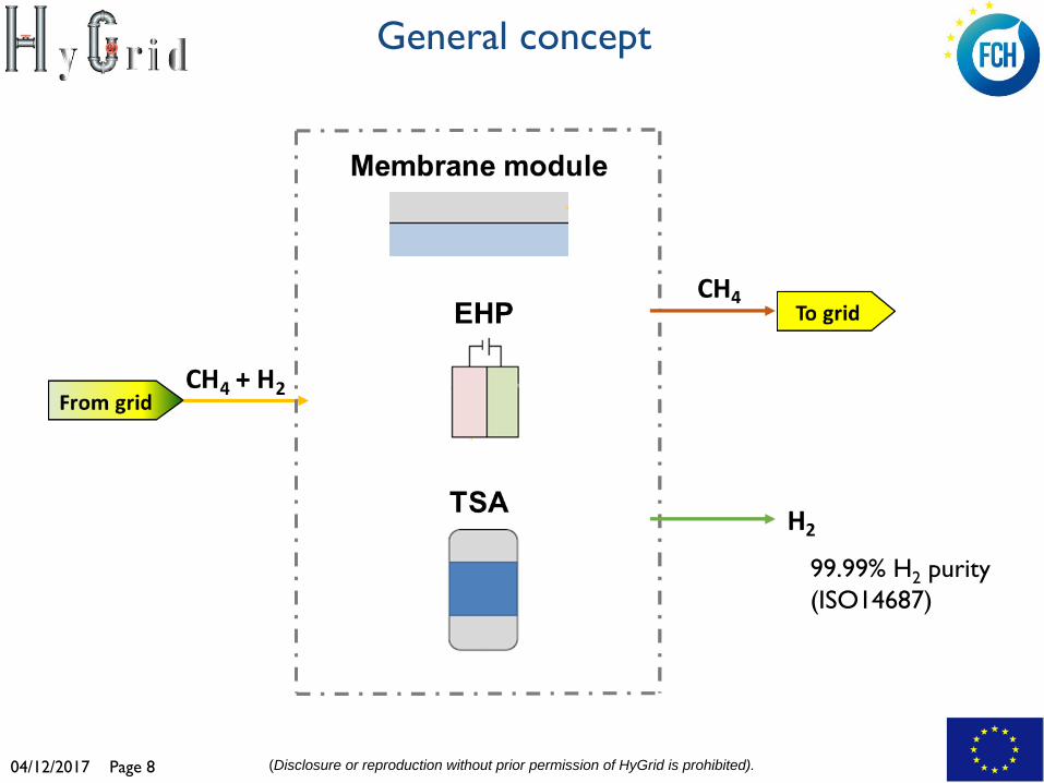
HyGrid aims at developing of an advanced high performance, cost effective separation technology for direct separation of hydrogen from natural gas networks.
The system will be based on:
Design, construction and testing of an novel membrane based hybrid technology for pure hydrogen production (ISO 14687) combining three technologies for hydrogen purification integrated in a way that enhances the strengths of each of them: membrane separation technology is employed for removing H2 from the “low H2 content” (e.g. 2-10 %) followed by electrochemical hydrogen separation (EHP ) optimal for the “very low H2 content” (e.g. <2 %) and finally temperature swing adsorption (TSA) technology to purify from humidity produced in both systems upstream.
The project targets a pure hydrogen separation system with power and cost of < 5 kWh/kgH2 and < 1.5 €/kgH2. A pilot designed for >25 kg/day of hydrogen will be built and tested at industrially relevant conditions (TRL 5).
04/12/2017 Page 8 (Disclosure or reproduction without prior permission of HyGrid is prohibited).
General concept
99.99% H2 purity (ISO14687)

04/12/2017 Page 9 (Disclosure or reproduction without prior permission of HyGrid is prohibited).
Partnership
Multidisciplinary and complementary team: 7 top level European organisations from 4 countries: 2 research institutes and 5 top industries (3 SME) in different sectors (from materials development to membrane modules and separation systems, etc.).
1 TU/e, Netherlands 2 TECNALIA, Spain 3 HYG, Netherlands 4 SAES, Italy 5 HYET, Netherlands 6 QUANTIS, Switzerland 7 Nortegas Energía, Spain

04/12/2017 Page 10 (Disclosure or reproduction without prior permission of HyGrid is prohibited).
Consortium
1 TU/e, Netherlands 2 TECNALIA, Spain 3 HYG, Netherlands 4 SAES, Italy 5 HYET, Netherlands 6 QUANTIS, Switzerland 7 Nortegas Energía, Spain

04/12/2017 Page 11 (Disclosure or reproduction without prior permission of HyGrid is prohibited).
Project objectives
Development of a hydrogen separation system capable of targeting low (2-10%) and very low (<2%) H2 blends in natural gas. o Membranes for H2 recovery from low hydrogen content streams (2-10%). o EHP for H2 recovery from very low concentration streams (<2%) . o TSA for water removal from hydrogen/water streams.
Technical validation of the novel modules at lab scale.
Optimization of the hybrid system.
Energy analysis of the new HyGrid technology on different scenarios: o recovery of H2 from low concentration streams (2% -10%) up to 99.99%
H2 purity (ISO14687) in the whole range of pressures of the NG grid. o Different configurations/combinations of the three separation technologies
The validation of the novel hybrid system at prototype scale (TLR 5)
The environmental LCA of the complete chain.
Dissemination and exploitation of the results.

04/12/2017 Page 12 (Disclosure or reproduction without prior permission of HyGrid is prohibited).
Work Structure - Partnership Synergies

04/12/2017 Page 13 (Disclosure or reproduction without prior permission of HyGrid is prohibited).
Membranes development
Development of cost effective tubular supported membranes for the recovery of hydrogen from low concentration streams (2% -10%) in the whole range of pressures of the Natural Gas Network. Two different types of membranes will be developed as well as the final membrane module: Pd-based membranes for the medium to the lowest Natural Gas
Grid pressures with improved flux and selectivity. Carbon Molecular Sieve membranes for the high pressure range. Membrane module for the prototype.
Objectives:

04/12/2017 Page 14 (Disclosure or reproduction without prior permission of HyGrid is prohibited).
Permation of H2 against H2/N2 selectivity
Mesoporous Ceramics (nm)
Zeolites Carbon
Microporous Ceramics (Å)
Palladium Palladium alloys
0.1
1
1000
100
10
10 100 1000 10000 ∞
Rela
tive
Hydr
ogen
per
mea
tion
H2/N2 selectivity
Inorganic, metallic & carbon membranes

04/12/2017 Page 15 (Disclosure or reproduction without prior permission of HyGrid is prohibited).
Nanopores + constrictions
Membrane thickness
Transport mechanism
Carbon Molecular Sieve membranes

04/12/2017 Page 16 (Disclosure or reproduction without prior permission of HyGrid is prohibited).
40 °C 4h 90 °C overnight
Dry
Carbonization
550 °C 2h 1°C/min under N2
vacuum
Dip coating
Preparation of composite Al2O3 – CMSM
Carbon Molecular Sieve membranes

04/12/2017 Page 17 (Disclosure or reproduction without prior permission of HyGrid is prohibited).
Gas permeation of composite Al-CMSM at various temperatures
Carbon Molecular Sieve membranes
Robeson plot of the of composite Al-CMSM

04/12/2017 Page 18 (Disclosure or reproduction without prior permission of HyGrid is prohibited).
Porous Support: Supplied by Rauschert 100nm pore size Al2O3
Pd-Ag membrane layer deposition by Electroless Plating technique
Join to dense ceramic tube at Tecnalia
~4 µm thick Pd-Ag membrane
Membrane length before
sealing: 14-15 cm
Pd-Ag
ZrO2 110 nm on Al2O3
Cross-section SEM image
Surface SEM image
Ceramic supported Pd-based membrane
04/12/2017 Page 19 (Disclosure or reproduction without prior permission of HyGrid is prohibited).
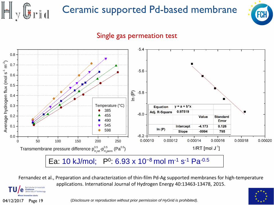
Single gas permeation test
0 50 100 150 200 2500.0
0.1
0.2
0.3
0.4
0.5
0.6
0.7
0.8
Temperature (°C) 385 455 490 545 598A
vera
ge h
ydro
gen
flux
(mol
s-1 m
-2)
Transmembrane pressure difference p0.5H2ret-p
0.5H2perm (Pa0.5)
Ea: 10 kJ/mol; P0: 6.93 x 10⁻⁸ mol m-1 s-1 Pa-0.5
Fernandez et al., Preparation and characterization of thin-film Pd-Ag supported membranes for high-temperature applications. International Journal of Hydrogen Energy 40:13463-13478, 2015.
Ceramic supported Pd-based membrane

04/12/2017 Page 20 (Disclosure or reproduction without prior permission of HyGrid is prohibited).
0
50000
100000
150000
200000
250000
300000
350000
0.0E+00
4.0E-07
8.0E-07
1.2E-06
1.6E-06
2.0E-06
2.4E-06
2.8E-06
0 100 200 300 400 500 600 700 800
Idea
l sel
ectiv
ity H
2/N2
Perm
eanc
e H 2
(mol
/s/m
2 /Pa)
Time (h)
500 °C 525 °C 550 °C 575 °C 600 °C
SH2/N2 = 2650
Membrane M17-E94. Long-term stability test (500-600 ºC)
Metallic supported membrane M14. Long-term stability test over time at 400 ºC
Long-term stability test
Medrano et al., Pd-based metallic supported membranes: high-temperature stability and fluidized bed reactor testing, International Journal of Hydrogen Energy, 2015. http://dx.doi.org/10.1016/j.ijhydene.2015.10.094
Metallic supported Pd-based membrane

04/12/2017 Page 21 (Disclosure or reproduction without prior permission of HyGrid is prohibited).
The thickness is controlled by the plating time There is a trade off between permeance and selectivity
Thickness versus plating time Selectivity and H2 permeance versus thickness
Ultra-thin (≈ 1 µm) supported Pd-Ag membranes by Electroless Plating
H2 permeance (400ºC)= 3.1x10⁻⁶ (mol m-2 s-1 Pa-1); H2/N2= 8,000 – 10,000 H2 permeance (400ºC)= 4.2x10⁻⁶ (mol m-2 s-1 Pa-1); H2/N2= 20,000
FluidCELL FCH JU – FP7 project (www.fluidcell.eu)

04/12/2017 Page 22 (Disclosure or reproduction without prior permission of HyGrid is prohibited).
Membrane Thickness Porous support
H2 permeance x10-7 mol m-2 s-1 Pa-1 @ ΔP 1 atm
H2/N2 selectivity
Thin Pd-Ag 4-5 µm Metallic ≈ 10 at 400 °C >100.000 Alumina* ≈ 30 at 400 °C >20.000
Ultra-thin Pd-Ag ≈ 1 µm Alumina ≈ 100 at 400 °C > 2.000 CMSM 3-4 µm Alumina ≈1 at 30°C ≈ 500
Separation properties of membranes previously developed at TECNALIA
* Over DOE targets 2015
Membrane Thickness Porous support
H2 permeance x10-7 mol m-2 s-1 Pa-1 @ ΔP 1 atm
H2/N2 selectivity
Thin Pd-Ag 4-5 µm Alumina ≈ 3,3 at 400 °C >20.000 Ultra-thin Pd-Ag ≈ 1 µm Alumina ≈ 11.8 at 400 °C > 2.000
Permeation tests at gas compositions similar to the HyGrid (90% CH4 & 10% H2)
Background on Pd-based membranes

04/12/2017 Page 23 (Disclosure or reproduction without prior permission of HyGrid is prohibited).
Electrochemical hydrogen separation development
Objectives: Development of an electrochemical hydrogen purifier (EHP) for the recovery of the hydrogen from very low concentration streams (≤ 2 %). Capable of recovering the majority of the remaining hydrogen from the
retentate of the membrane separator. Optimum configuration of membrane-electrode-assembly for low
concentration hydrogen extraction. Theoretical modelling assisted optimum design of stack and gas
distribution plate geometry for low concentration electrochemical hydrogen extraction (<3%).
Construction and testing of sub- and full size electrochemical
compressor stacks for model validation and prototype preparation.

04/12/2017 Page 24 (Disclosure or reproduction without prior permission of HyGrid is prohibited).
Electrochemical hydrogen separation development
Key performance indicators for EHP:
Working principle:

04/12/2017 Page 25 (Disclosure or reproduction without prior permission of HyGrid is prohibited).
Electrochemical hydrogen separation development
Modelling EHP: Model set up in Matlab for EHP system configurations to find setup of the system meeting the KPIs Iterations: Operating temperature Number of cells Type of membrane Hydrogen concentration Pressure
Conclusion: Meeting the KPIs for EHP is possible with the right number of cells, operating temperature, membrane and pressure for hydrogen concentration in the feed gas between 2 and 10%

04/12/2017 Page 26 (Disclosure or reproduction without prior permission of HyGrid is prohibited).
Electrochemical hydrogen separation development
Sub scale testing EHP: Platform HCS100 developed, capable of pure hydrogen pressure of 700 bar and pump rate (current density) of 1 A/cm2
Conclusions purification testing: Two flow field design tested and analysed. One has been selected Humifidication of feed gas highly influences stable performance of EHP Outlook: Review anode flow field design needed for HyGrid EHP cell: lowering
pressure drop and expanding holdup time in EHP cell Continuing testing on stability for multi-cell stacks

04/12/2017 Page 27 (Disclosure or reproduction without prior permission of HyGrid is prohibited).
Electrochemical hydrogen separation development
System development around EHP: Small scale system tested in Rozenburg (NL), started within project PurifHy. Established base-line EHP performance with sub-optimal EHP cell hardware. Conclusion: 90% recovery rate is feasible with high surface area and with
high energy demand
recovery rate
The Rozenburg test location Testing data Rozenburg

04/12/2017 Page 28 (Disclosure or reproduction without prior permission of HyGrid is prohibited).
Temperature Swing Adsorption development
Objectives: Design, construction and test of the TSA unit. Better comprehension of the behaviour and performance of the
adsorption materials used in TSA. Understanding of the response of adsorbents to the dynamic
temperature control. Implementation of the know-how gained through lab tests onto the up-
scaled design. Design of prototype TSA unit for integration in pilot scale HyGrid
system.
Testing of pilot scale TSA unit.
04/12/2017 Page 29 (Disclosure or reproduction without prior permission of HyGrid is prohibited).
Development of TSA strategy and sizing
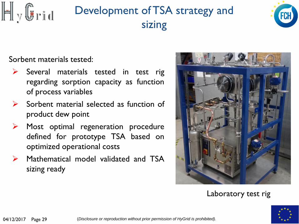
Sorbent materials tested: Several materials tested in test rig
regarding sorption capacity as function of process variables
Sorbent material selected as function of product dew point
Most optimal regeneration procedure defined for prototype TSA based on optimized operational costs
Mathematical model validated and TSA sizing ready
Laboratory test rig

04/12/2017 Page 30 (Disclosure or reproduction without prior permission of HyGrid is prohibited).
Prototype TSA
Prototype TSA: • Process flow diagram defined • Operational safety assessed • Control strategy implemented • Prototype assembly ready
Next steps: testing prototype integration with membrane and EHP module
Ads 1(producing)
Ads 2(regenerating)
Feed
Heater
Product
Cooler/condenser
Regeneration gas compressor
G/L separator
Water
cooling
heati ng
Regeneration gas
PFD prototype TSA Prototype TSA assembly

04/12/2017 Page 31 (Disclosure or reproduction without prior permission of HyGrid is prohibited).
Lab scale testing
Objectives: Design and test a small version of the prototype and test it at lab scale especially in conditions not feasible for the prototype. Investigate the recovery of the membrane system at different pressures
and different concentrations of hydrogen.
Sorbents for the TSA selected will be further studied in TGA experiments to evaluate the cyclic sorbent capacity and adsorption isotherms.
Evaluation of different configurations to identify the optimum separation
system along the natural gas network.

04/12/2017 Page 32 (Disclosure or reproduction without prior permission of HyGrid is prohibited).
A small test rig will be updated at TUE to be able to test smaller versions of the hybrid separation technology of HyGrid at different conditions. In particular the system will be designed to be able to work at up to 20 bar (now up to 50 bar) at low hydrogen contents recovery
Design and building of the lab scale rig

04/12/2017 Page 33 (Disclosure or reproduction without prior permission of HyGrid is prohibited).
0.03
0.08
0.13
0.18
0.23
0.28
35 85 135 185
Hyd
roge
n re
cove
ry fa
ctor
[-]
Hydrogen partial pressure [Pa0.5]
0.3 l/min sweep gas
0.5 l/min sweep gas
0.7 l/min sweep gas
1 l/min sweep gas
1.5 l/min sweep gas
2 l/min sweep gas
3 l/min sweep gas
0
0.2
0.4
0.6
0.8
1
1.2
1.4
1.6
1.8
2
0 100 200 300 400
Hyd
roge
n pe
rmea
tion
[mol
/s/m
2 ]
Hydrogen partial pressure [Pa0.5]
T=418C ultra-thin E635T=382C ultra-thin E635T=426C ultra-thin E633T=370C ultra-thin E633T=427C ultra-thin E689T=391 C ultra-thin E689
Different Pd-Ag membranes has been tested changing the following operating conditions: Temperature and pressure
Type and amount of sweep gas
Testing of membranes and sorbents

04/12/2017 Page 34 (Disclosure or reproduction without prior permission of HyGrid is prohibited).
0.04
0.06
0.08
0.1
0.12
0.14
0 2000 4000 6000 8000 10000 12000 14000
H2
perm
eate
[l/m
in]
Logarithmic partial pressure [Pa]
10% H2 1.5l/min sweepgas10% H21l/min sweepgas10% H2 0.8l/min sweepgas10% H2 0.9l/min sweepgas
0
500
1000
1500
2000
2500
3000
3500
0 200 400 600 800 1000 1200
H2
perm
eatio
n [m
l/min
]
pressure difference [Pa0.58]
70%CH4 30%H260%CH4 40% H250%CH4 50%H240%CH4 60%H230%CH4 70%H220%CH4 80%H210%CH4 90%H2
Changing H2 concentration
Changing H2 concentration
with sweep gas
0
0.05
0.1
0.15
0.2
0.25
0.3
0.35
0 100 200 300 400 500 600
H2
perm
eate
[l/m
in]
Average partial pressure of hydrogen [Pa0.595]
20% H2 0.3l/min sweep gas
20% H2 0.4l/min sweep gas
20% H2 0.6l/min sweep gas
20% H2 0.8l/min sweep gas
20% H2 1l/minsweep gas
Testing of membranes and sorbents

04/12/2017 Page 35 (Disclosure or reproduction without prior permission of HyGrid is prohibited).
0.0000
0.0200
0.0400
0.0600
0.0800
0.1000
0.1200
0.1400
0.1600
0.1800
0.2000
0.0000 0.0100 0.0200 0.0300 0.0400 0.0500 0.0600
weig
ht d
iffer
ence
[-]
H2O partial pressure [bar]
45C silica
55C silica
65C silica
45C zeolite 4A
55C zeolite 4A
65C zeolite 4A
Zeolite 4A, modified zeolite 4A, zeolite 13X and silica have been tested at different temperature and different steam content in order to study the adsorption capacity.
0
0.05
0.1
0.15
0.2
0.25
0.3
0 0.1 0.2 0.3 0.4 0.5 0.6
wei
ght d
iffer
ence
[-]
Steam partial pressure [bar]
100 C90C80C
There is a significant difference between zeolite and silica in adsorption capacity.
Testing of membranes and sorbents

04/12/2017 Page 36 (Disclosure or reproduction without prior permission of HyGrid is prohibited).
Prototype integration and validation
Objectives:
Design of the integrated hydrogen recovery pilot plant Construct and assemble the hydrogen recovery pilot plant
including controls Testing and assessment of hydrogen recovery pilot plant

04/12/2017 Page 37 (Disclosure or reproduction without prior permission of HyGrid is prohibited).
System modelling and simulation
Objectives: To assess the energy analysis, and economic performance (in terms of primary energy consumption and cost of pure H2) of the HyGrid system for H2 separation from NG grid. Membrane module model and simulation. Development of dynamic model for TSA. Modelling of electrochemical separation and compression.
Simulation and economic optimization of integrated hydrogen recovery

04/12/2017 Page 38 (Disclosure or reproduction without prior permission of HyGrid is prohibited).
PHb H2 partial
pressure in the bulk
PHl Hydrogen partial pressure in the
bulk
H2 partial pressure on the
surface PHs
There are 3 different possible mass transfers in the Pd membrane: Retentate side Porous support Permeate side
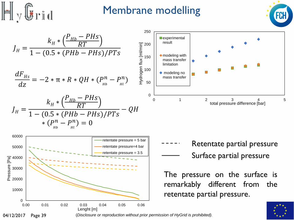
The difference between experimental and modelled results should be find in the mass transfer limitation due to a hydrogen-depleted layer adjacent to the membrane surface.
Membrane modelling
04/12/2017 Page 39 (Disclosure or reproduction without prior permission of HyGrid is prohibited).
0
10000
20000
30000
40000
50000
60000
0.00 0.01 0.02 0.03 0.04 0.05 0.06
Pres
sure
[Pa]
Lenght [m]
retentate pressure = 5 bar
retentate pressure=4 bar
retentate pressure = 3.5
The pressure on the surface is remarkably different from the retentate partial pressure.
0
50
100
150
200
250
0 1 2 3 4 5
Hyd
roge
n flu
x [m
l/min
]
total pressure difference [bar]
experimentalresult
modeling withmass transferlimitation
modeling nomass transfer
𝐽𝐻 =𝑘𝐻 ∗
𝑃𝐻𝐻 − 𝑃𝐻𝑃𝑅𝑅
1 − (0.5 ∗ (𝑃𝐻𝐻 − 𝑃𝐻𝑃)/𝑃𝑅𝑃
𝑑𝑑𝐻𝑃𝑑𝑑 = −2 ∗ π ∗ 𝑅 ∗ 𝑄𝐻 ∗ (𝑃
𝐻𝐻
𝑛 − 𝑃𝐻𝐻
𝑛)
Surface partial pressure Retentate partial pressure
𝐽𝐻 =𝑘𝐻 ∗
𝑃𝐻𝐻 − 𝑃𝐻𝑃𝑅𝑅
1 − (0.5 ∗ (𝑃𝐻𝐻 − 𝑃𝐻𝑃)/𝑃𝑅𝑃 − 𝑄𝐻
∗ 𝑃𝐻𝐻
𝑛 − 𝑃𝐻𝐻
𝑛 = 0
Membrane modelling

04/12/2017 Page 40 (Disclosure or reproduction without prior permission of HyGrid is prohibited).
Total electric consumption 3.9 kWh/kgH2 < 5 kWh/kgH2 Total hydrogen separated 27.26 kgH2/day > 25 kgH2/day
purity 99.98 % > 99.97 % HRF 90 % > 85 %
Total membrane area 3.33 m2
Total electric consumption 3.88 kWh/kgH2 < 5 kWh/kgH2 Total hydrogen separated 26.055 kgH2/day > 25 kgH2/day
purity 99.977 % > 99.97 % HRF 86.906 % > 85 %
Total membrane area 4.91 m2
Two different configuration has been modelled to optmize the targets required
First case: two membrane modules
Second case: one membrane module
Simulation of the hybrid system

04/12/2017 Page 41 (Disclosure or reproduction without prior permission of HyGrid is prohibited).
Environmental LCA and economic assessment
The new H2 separation technology will be analysed and compared to other available technologies using LCA and LCC in an iterative process to guide the design and development of the novel technologies and products towards sustainable solutions.
Environmental
Constraints
Safety Constraints
Process Performance Constraints
An Environmental Life Cycle Assessment will be performed by applying and testing the most up-to-date life cycle impact assessment methods
Life Cycle Costing will be performed and the latest advances in monetary valuation of impacts will be tested
A business plan will be developed as part of the economic assessment

04/12/2017 Page 42 (Disclosure or reproduction without prior permission of HyGrid is prohibited).
Overall, the main questions analysed during the goal and scope development include:
What is the aim of the study?
What is the function of the analysed system?
What systems exactly are going to be analysed?
What reference system/ technology will we compare our system against?
What are the system boundaries of the analysed product?
What environmental indicators will be calculated?
What is the data availability for the study?
Goal and scope definition

04/12/2017 Page 43 (Disclosure or reproduction without prior permission of HyGrid is prohibited).
Functional unit: “The recovery from an average European natural gas grid of 1 kg of hydrogen with a purity of at least 99.97%.”
Reference technology (to compare with the HyGrid system): pressure swing adsorption (PSA)
Main outcomes of goal and scope definition

04/12/2017 Page 44 (Disclosure or reproduction without prior permission of HyGrid is prohibited).
System boundaries

04/12/2017 Page 45 (Disclosure or reproduction without prior permission of HyGrid is prohibited).
Flexible Hybrid separation system for H2 recovery from NG Grids
HyGrid
Thank you for your attention Contacts: [email protected]
https://www.hygrid-h2.eu/