Embed Size (px)
Citation preview

RESIDENTIAL • COMMERCIAL • INDUSTRIALRESIDENTIAL • COMMERCIAL • INDUSTRIALFGP-001, Rev. 06-09
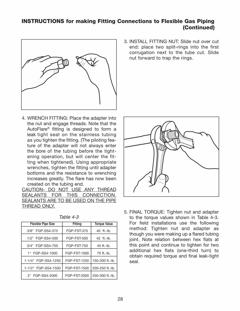
FLEXIBLE GAS PIPINGDESIGN GUIDE
andINSTALLATION INSTRUCTIONS
June 2009
FLEXIBLE GAS PIPINGDESIGN GUIDE
andINSTALLATION INSTRUCTIONS
June 2009
®
111743_OmegaFlex_Cvr:111743_OmegaFlex_Cvr 5/26/09 4:43 PM Page 1
111743_OmegaFlex_Cvr:111743_OmegaFlex_Cvr 5/26/09 4:43 PM Page 2
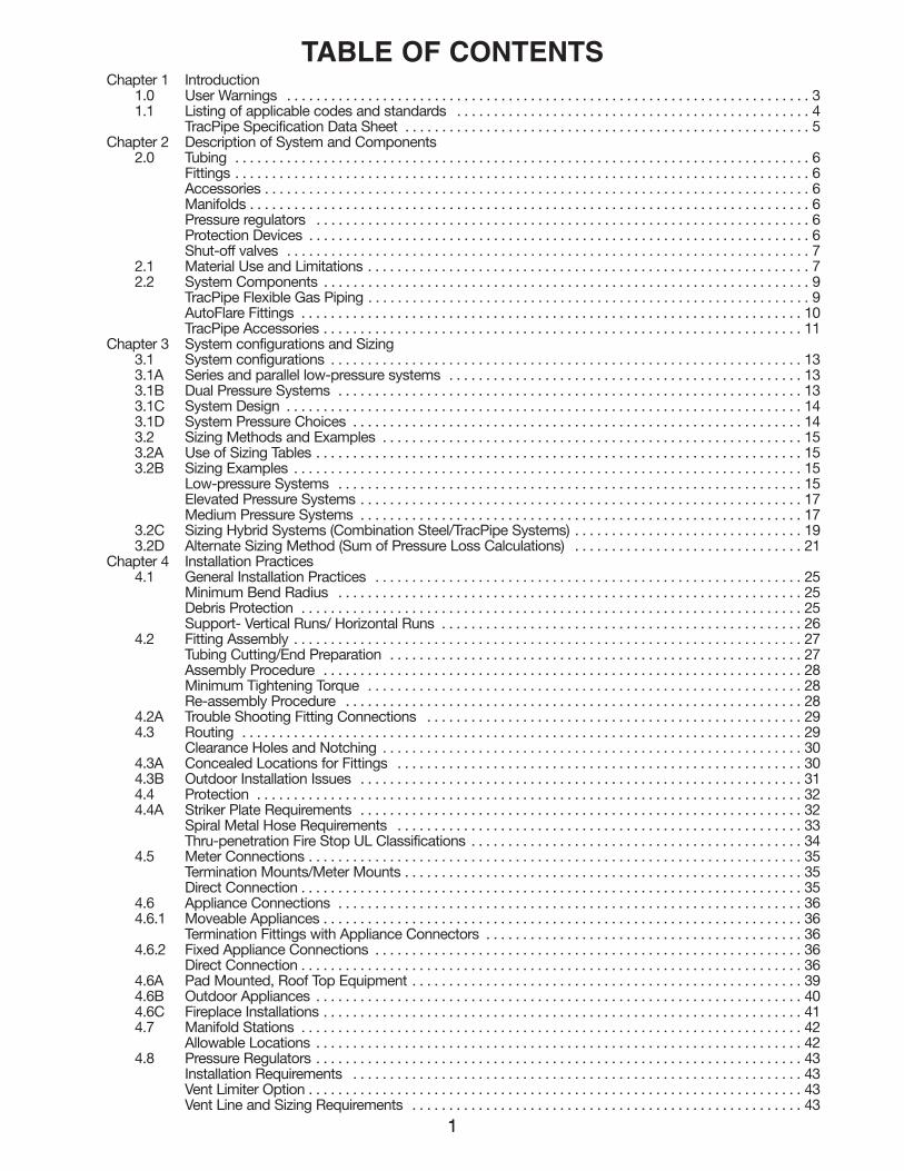
TABLE OF CONTENTS
11
Chapter 1 Introduction 1.0 User Warnings . . . . . . . . . . . . . . . . . . . . . . . . . . . . . . . . . . . . . . . . . . . . . . . . . . . . . . . . . . . . . . . . . . . . . . . 31.1 Listing of applicable codes and standards . . . . . . . . . . . . . . . . . . . . . . . . . . . . . . . . . . . . . . . . . . . . . . . . 4
TracPipe Specification Data Sheet . . . . . . . . . . . . . . . . . . . . . . . . . . . . . . . . . . . . . . . . . . . . . . . . . . . . . . . 5Chapter 2 Description of System and Components
2.0 Tubing . . . . . . . . . . . . . . . . . . . . . . . . . . . . . . . . . . . . . . . . . . . . . . . . . . . . . . . . . . . . . . . . . . . . . . . . . . . . . . 6Fittings . . . . . . . . . . . . . . . . . . . . . . . . . . . . . . . . . . . . . . . . . . . . . . . . . . . . . . . . . . . . . . . . . . . . . . . . . . . . . . 6Accessories . . . . . . . . . . . . . . . . . . . . . . . . . . . . . . . . . . . . . . . . . . . . . . . . . . . . . . . . . . . . . . . . . . . . . . . . . . 6Manifolds . . . . . . . . . . . . . . . . . . . . . . . . . . . . . . . . . . . . . . . . . . . . . . . . . . . . . . . . . . . . . . . . . . . . . . . . . . . . 6Pressure regulators . . . . . . . . . . . . . . . . . . . . . . . . . . . . . . . . . . . . . . . . . . . . . . . . . . . . . . . . . . . . . . . . . . . 6Protection Devices . . . . . . . . . . . . . . . . . . . . . . . . . . . . . . . . . . . . . . . . . . . . . . . . . . . . . . . . . . . . . . . . . . . . 6Shut-off valves . . . . . . . . . . . . . . . . . . . . . . . . . . . . . . . . . . . . . . . . . . . . . . . . . . . . . . . . . . . . . . . . . . . . . . . 7
2.1 Material Use and Limitations . . . . . . . . . . . . . . . . . . . . . . . . . . . . . . . . . . . . . . . . . . . . . . . . . . . . . . . . . . . . 72.2 System Components . . . . . . . . . . . . . . . . . . . . . . . . . . . . . . . . . . . . . . . . . . . . . . . . . . . . . . . . . . . . . . . . . . 9
TracPipe Flexible Gas Piping . . . . . . . . . . . . . . . . . . . . . . . . . . . . . . . . . . . . . . . . . . . . . . . . . . . . . . . . . . . . 9AutoFlare Fittings . . . . . . . . . . . . . . . . . . . . . . . . . . . . . . . . . . . . . . . . . . . . . . . . . . . . . . . . . . . . . . . . . . . . 10TracPipe Accessories . . . . . . . . . . . . . . . . . . . . . . . . . . . . . . . . . . . . . . . . . . . . . . . . . . . . . . . . . . . . . . . . . 11
Chapter 3 System configurations and Sizing3.1 System configurations . . . . . . . . . . . . . . . . . . . . . . . . . . . . . . . . . . . . . . . . . . . . . . . . . . . . . . . . . . . . . . . . 133.1A Series and parallel low-pressure systems . . . . . . . . . . . . . . . . . . . . . . . . . . . . . . . . . . . . . . . . . . . . . . . . 133.1B Dual Pressure Systems . . . . . . . . . . . . . . . . . . . . . . . . . . . . . . . . . . . . . . . . . . . . . . . . . . . . . . . . . . . . . . . 133.1C System Design . . . . . . . . . . . . . . . . . . . . . . . . . . . . . . . . . . . . . . . . . . . . . . . . . . . . . . . . . . . . . . . . . . . . . . 143.1D System Pressure Choices . . . . . . . . . . . . . . . . . . . . . . . . . . . . . . . . . . . . . . . . . . . . . . . . . . . . . . . . . . . . . 143.2 Sizing Methods and Examples . . . . . . . . . . . . . . . . . . . . . . . . . . . . . . . . . . . . . . . . . . . . . . . . . . . . . . . . . 153.2A Use of Sizing Tables . . . . . . . . . . . . . . . . . . . . . . . . . . . . . . . . . . . . . . . . . . . . . . . . . . . . . . . . . . . . . . . . . . 153.2B Sizing Examples . . . . . . . . . . . . . . . . . . . . . . . . . . . . . . . . . . . . . . . . . . . . . . . . . . . . . . . . . . . . . . . . . . . . . 15
Low-pressure Systems . . . . . . . . . . . . . . . . . . . . . . . . . . . . . . . . . . . . . . . . . . . . . . . . . . . . . . . . . . . . . . . 15Elevated Pressure Systems . . . . . . . . . . . . . . . . . . . . . . . . . . . . . . . . . . . . . . . . . . . . . . . . . . . . . . . . . . . . 17Medium Pressure Systems . . . . . . . . . . . . . . . . . . . . . . . . . . . . . . . . . . . . . . . . . . . . . . . . . . . . . . . . . . . . 17
3.2C Sizing Hybrid Systems (Combination Steel/TracPipe Systems) . . . . . . . . . . . . . . . . . . . . . . . . . . . . . . . 193.2D Alternate Sizing Method (Sum of Pressure Loss Calculations) . . . . . . . . . . . . . . . . . . . . . . . . . . . . . . . 21
Chapter 4 Installation Practices 4.1 General Installation Practices . . . . . . . . . . . . . . . . . . . . . . . . . . . . . . . . . . . . . . . . . . . . . . . . . . . . . . . . . . 25
Minimum Bend Radius . . . . . . . . . . . . . . . . . . . . . . . . . . . . . . . . . . . . . . . . . . . . . . . . . . . . . . . . . . . . . . . 25Debris Protection . . . . . . . . . . . . . . . . . . . . . . . . . . . . . . . . . . . . . . . . . . . . . . . . . . . . . . . . . . . . . . . . . . . . 25Support- Vertical Runs/ Horizontal Runs . . . . . . . . . . . . . . . . . . . . . . . . . . . . . . . . . . . . . . . . . . . . . . . . . 26
4.2 Fitting Assembly . . . . . . . . . . . . . . . . . . . . . . . . . . . . . . . . . . . . . . . . . . . . . . . . . . . . . . . . . . . . . . . . . . . . . 27Tubing Cutting/End Preparation . . . . . . . . . . . . . . . . . . . . . . . . . . . . . . . . . . . . . . . . . . . . . . . . . . . . . . . . 27Assembly Procedure . . . . . . . . . . . . . . . . . . . . . . . . . . . . . . . . . . . . . . . . . . . . . . . . . . . . . . . . . . . . . . . . . 28Minimum Tightening Torque . . . . . . . . . . . . . . . . . . . . . . . . . . . . . . . . . . . . . . . . . . . . . . . . . . . . . . . . . . . 28Re-assembly Procedure . . . . . . . . . . . . . . . . . . . . . . . . . . . . . . . . . . . . . . . . . . . . . . . . . . . . . . . . . . . . . . 28
4.2A Trouble Shooting Fitting Connections . . . . . . . . . . . . . . . . . . . . . . . . . . . . . . . . . . . . . . . . . . . . . . . . . . . 294.3 Routing . . . . . . . . . . . . . . . . . . . . . . . . . . . . . . . . . . . . . . . . . . . . . . . . . . . . . . . . . . . . . . . . . . . . . . . . . . . . 29
Clearance Holes and Notching . . . . . . . . . . . . . . . . . . . . . . . . . . . . . . . . . . . . . . . . . . . . . . . . . . . . . . . . . 304.3A Concealed Locations for Fittings . . . . . . . . . . . . . . . . . . . . . . . . . . . . . . . . . . . . . . . . . . . . . . . . . . . . . . . 304.3B Outdoor Installation Issues . . . . . . . . . . . . . . . . . . . . . . . . . . . . . . . . . . . . . . . . . . . . . . . . . . . . . . . . . . . . 314.4 Protection . . . . . . . . . . . . . . . . . . . . . . . . . . . . . . . . . . . . . . . . . . . . . . . . . . . . . . . . . . . . . . . . . . . . . . . . . . 324.4A Striker Plate Requirements . . . . . . . . . . . . . . . . . . . . . . . . . . . . . . . . . . . . . . . . . . . . . . . . . . . . . . . . . . . . 32
Spiral Metal Hose Requirements . . . . . . . . . . . . . . . . . . . . . . . . . . . . . . . . . . . . . . . . . . . . . . . . . . . . . . . 33Thru-penetration Fire Stop UL Classifications . . . . . . . . . . . . . . . . . . . . . . . . . . . . . . . . . . . . . . . . . . . . . 34
4.5 Meter Connections . . . . . . . . . . . . . . . . . . . . . . . . . . . . . . . . . . . . . . . . . . . . . . . . . . . . . . . . . . . . . . . . . . . 35Termination Mounts/Meter Mounts . . . . . . . . . . . . . . . . . . . . . . . . . . . . . . . . . . . . . . . . . . . . . . . . . . . . . . 35Direct Connection . . . . . . . . . . . . . . . . . . . . . . . . . . . . . . . . . . . . . . . . . . . . . . . . . . . . . . . . . . . . . . . . . . . . 35
4.6 Appliance Connections . . . . . . . . . . . . . . . . . . . . . . . . . . . . . . . . . . . . . . . . . . . . . . . . . . . . . . . . . . . . . . . 364.6.1 Moveable Appliances . . . . . . . . . . . . . . . . . . . . . . . . . . . . . . . . . . . . . . . . . . . . . . . . . . . . . . . . . . . . . . . . . 36
Termination Fittings with Appliance Connectors . . . . . . . . . . . . . . . . . . . . . . . . . . . . . . . . . . . . . . . . . . . 364.6.2 Fixed Appliance Connections . . . . . . . . . . . . . . . . . . . . . . . . . . . . . . . . . . . . . . . . . . . . . . . . . . . . . . . . . . 36
Direct Connection . . . . . . . . . . . . . . . . . . . . . . . . . . . . . . . . . . . . . . . . . . . . . . . . . . . . . . . . . . . . . . . . . . . . 364.6A Pad Mounted, Roof Top Equipment . . . . . . . . . . . . . . . . . . . . . . . . . . . . . . . . . . . . . . . . . . . . . . . . . . . . . 394.6B Outdoor Appliances . . . . . . . . . . . . . . . . . . . . . . . . . . . . . . . . . . . . . . . . . . . . . . . . . . . . . . . . . . . . . . . . . . 404.6C Fireplace Installations . . . . . . . . . . . . . . . . . . . . . . . . . . . . . . . . . . . . . . . . . . . . . . . . . . . . . . . . . . . . . . . . . 414.7 Manifold Stations . . . . . . . . . . . . . . . . . . . . . . . . . . . . . . . . . . . . . . . . . . . . . . . . . . . . . . . . . . . . . . . . . . . . 42
Allowable Locations . . . . . . . . . . . . . . . . . . . . . . . . . . . . . . . . . . . . . . . . . . . . . . . . . . . . . . . . . . . . . . . . . . 424.8 Pressure Regulators . . . . . . . . . . . . . . . . . . . . . . . . . . . . . . . . . . . . . . . . . . . . . . . . . . . . . . . . . . . . . . . . . . 43
Installation Requirements . . . . . . . . . . . . . . . . . . . . . . . . . . . . . . . . . . . . . . . . . . . . . . . . . . . . . . . . . . . . . 43Vent Limiter Option . . . . . . . . . . . . . . . . . . . . . . . . . . . . . . . . . . . . . . . . . . . . . . . . . . . . . . . . . . . . . . . . . . . 43Vent Line and Sizing Requirements . . . . . . . . . . . . . . . . . . . . . . . . . . . . . . . . . . . . . . . . . . . . . . . . . . . . . 43
111743_OmegaFlex_Txt:111743_OmegaFlex_Txt 5/28/09 11:56 AM Page 1
22
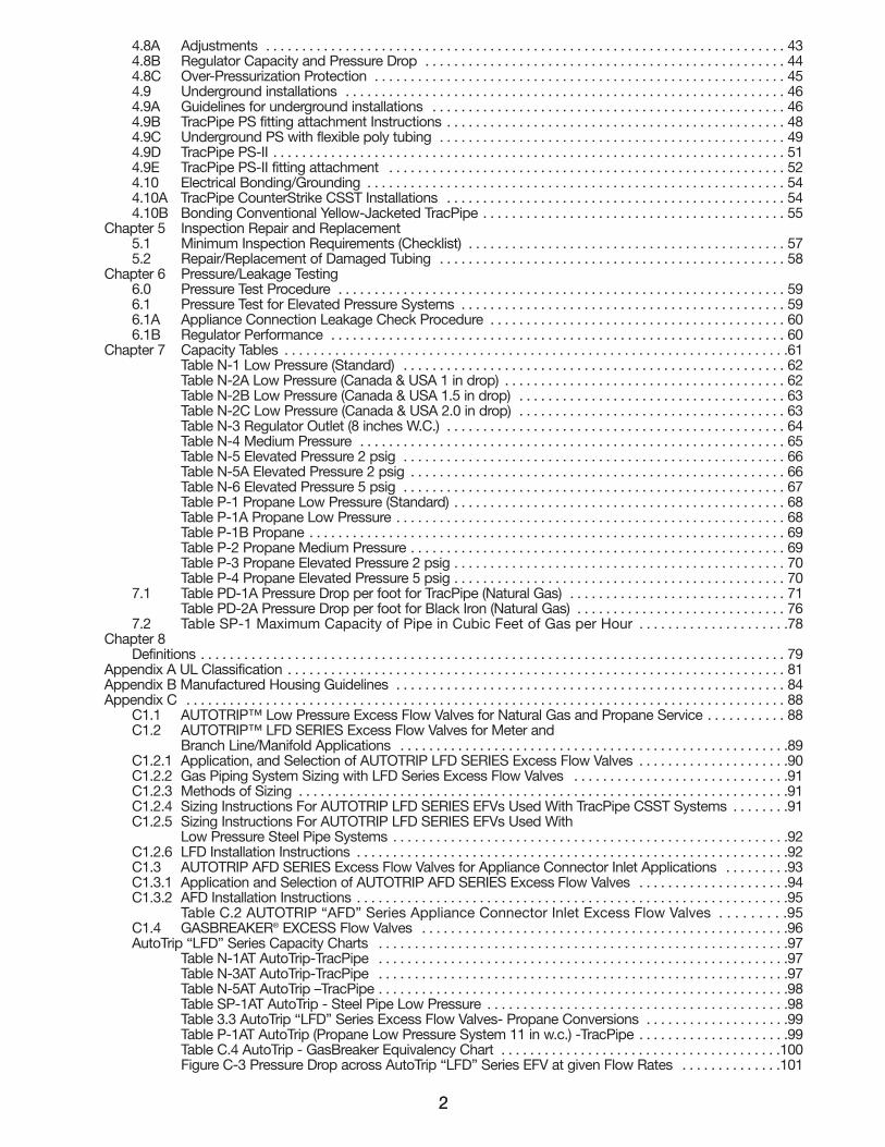
4.8A Adjustments . . . . . . . . . . . . . . . . . . . . . . . . . . . . . . . . . . . . . . . . . . . . . . . . . . . . . . . . . . . . . . . . . . . . . . . . 434.8B Regulator Capacity and Pressure Drop . . . . . . . . . . . . . . . . . . . . . . . . . . . . . . . . . . . . . . . . . . . . . . . . . . 444.8C Over-Pressurization Protection . . . . . . . . . . . . . . . . . . . . . . . . . . . . . . . . . . . . . . . . . . . . . . . . . . . . . . . . . 454.9 Underground installations . . . . . . . . . . . . . . . . . . . . . . . . . . . . . . . . . . . . . . . . . . . . . . . . . . . . . . . . . . . . . 464.9A Guidelines for underground installations . . . . . . . . . . . . . . . . . . . . . . . . . . . . . . . . . . . . . . . . . . . . . . . . . 464.9B TracPipe PS fitting attachment Instructions . . . . . . . . . . . . . . . . . . . . . . . . . . . . . . . . . . . . . . . . . . . . . . . 484.9C Underground PS with flexible poly tubing . . . . . . . . . . . . . . . . . . . . . . . . . . . . . . . . . . . . . . . . . . . . . . . . 494.9D TracPipe PS-II . . . . . . . . . . . . . . . . . . . . . . . . . . . . . . . . . . . . . . . . . . . . . . . . . . . . . . . . . . . . . . . . . . . . . . . 514.9E TracPipe PS-II fitting attachment . . . . . . . . . . . . . . . . . . . . . . . . . . . . . . . . . . . . . . . . . . . . . . . . . . . . . . . 524.10 Electrical Bonding/Grounding . . . . . . . . . . . . . . . . . . . . . . . . . . . . . . . . . . . . . . . . . . . . . . . . . . . . . . . . . . 544.10A TracPipe CounterStrike CSST Installations . . . . . . . . . . . . . . . . . . . . . . . . . . . . . . . . . . . . . . . . . . . . . . . 544.10B Bonding Conventional Yellow-Jacketed TracPipe . . . . . . . . . . . . . . . . . . . . . . . . . . . . . . . . . . . . . . . . . . 55
Chapter 5 Inspection Repair and Replacement5.1 Minimum Inspection Requirements (Checklist) . . . . . . . . . . . . . . . . . . . . . . . . . . . . . . . . . . . . . . . . . . . . 575.2 Repair/Replacement of Damaged Tubing . . . . . . . . . . . . . . . . . . . . . . . . . . . . . . . . . . . . . . . . . . . . . . . . 58
Chapter 6 Pressure/Leakage Testing 6.0 Pressure Test Procedure . . . . . . . . . . . . . . . . . . . . . . . . . . . . . . . . . . . . . . . . . . . . . . . . . . . . . . . . . . . . . . 596.1 Pressure Test for Elevated Pressure Systems . . . . . . . . . . . . . . . . . . . . . . . . . . . . . . . . . . . . . . . . . . . . . 596.1A Appliance Connection Leakage Check Procedure . . . . . . . . . . . . . . . . . . . . . . . . . . . . . . . . . . . . . . . . . 606.1B Regulator Performance . . . . . . . . . . . . . . . . . . . . . . . . . . . . . . . . . . . . . . . . . . . . . . . . . . . . . . . . . . . . . . . 60
Chapter 7 Capacity Tables . . . . . . . . . . . . . . . . . . . . . . . . . . . . . . . . . . . . . . . . . . . . . . . . . . . . . . . . . . . . . . . . . . . . . .61 Table N-1 Low Pressure (Standard) . . . . . . . . . . . . . . . . . . . . . . . . . . . . . . . . . . . . . . . . . . . . . . . . . . . . . 62Table N-2A Low Pressure (Canada & USA 1 in drop) . . . . . . . . . . . . . . . . . . . . . . . . . . . . . . . . . . . . . . . 62Table N-2B Low Pressure (Canada & USA 1.5 in drop) . . . . . . . . . . . . . . . . . . . . . . . . . . . . . . . . . . . . . 63Table N-2C Low Pressure (Canada & USA 2.0 in drop) . . . . . . . . . . . . . . . . . . . . . . . . . . . . . . . . . . . . . 63Table N-3 Regulator Outlet (8 inches W.C.) . . . . . . . . . . . . . . . . . . . . . . . . . . . . . . . . . . . . . . . . . . . . . . . 64Table N-4 Medium Pressure . . . . . . . . . . . . . . . . . . . . . . . . . . . . . . . . . . . . . . . . . . . . . . . . . . . . . . . . . . . 65Table N-5 Elevated Pressure 2 psig . . . . . . . . . . . . . . . . . . . . . . . . . . . . . . . . . . . . . . . . . . . . . . . . . . . . . 66Table N-5A Elevated Pressure 2 psig . . . . . . . . . . . . . . . . . . . . . . . . . . . . . . . . . . . . . . . . . . . . . . . . . . . . 66Table N-6 Elevated Pressure 5 psig . . . . . . . . . . . . . . . . . . . . . . . . . . . . . . . . . . . . . . . . . . . . . . . . . . . . . 67Table P-1 Propane Low Pressure (Standard) . . . . . . . . . . . . . . . . . . . . . . . . . . . . . . . . . . . . . . . . . . . . . . 68Table P-1A Propane Low Pressure . . . . . . . . . . . . . . . . . . . . . . . . . . . . . . . . . . . . . . . . . . . . . . . . . . . . . . 68Table P-1B Propane . . . . . . . . . . . . . . . . . . . . . . . . . . . . . . . . . . . . . . . . . . . . . . . . . . . . . . . . . . . . . . . . . . 69Table P-2 Propane Medium Pressure . . . . . . . . . . . . . . . . . . . . . . . . . . . . . . . . . . . . . . . . . . . . . . . . . . . . 69Table P-3 Propane Elevated Pressure 2 psig . . . . . . . . . . . . . . . . . . . . . . . . . . . . . . . . . . . . . . . . . . . . . . 70Table P-4 Propane Elevated Pressure 5 psig . . . . . . . . . . . . . . . . . . . . . . . . . . . . . . . . . . . . . . . . . . . . . . 70
7.1 Table PD-1A Pressure Drop per foot for TracPipe (Natural Gas) . . . . . . . . . . . . . . . . . . . . . . . . . . . . . . 71Table PD-2A Pressure Drop per foot for Black Iron (Natural Gas) . . . . . . . . . . . . . . . . . . . . . . . . . . . . . 76
7.2 Table SP-1 Maximum Capacity of Pipe in Cubic Feet of Gas per Hour . . . . . . . . . . . . . . . . . . . . .78 Chapter 8
Definitions . . . . . . . . . . . . . . . . . . . . . . . . . . . . . . . . . . . . . . . . . . . . . . . . . . . . . . . . . . . . . . . . . . . . . . . . . . . . . . . . . 79Appendix A UL Classification . . . . . . . . . . . . . . . . . . . . . . . . . . . . . . . . . . . . . . . . . . . . . . . . . . . . . . . . . . . . . . . . . . . . . 81Appendix B Manufactured Housing Guidelines . . . . . . . . . . . . . . . . . . . . . . . . . . . . . . . . . . . . . . . . . . . . . . . . . . . . . . 84Appendix C . . . . . . . . . . . . . . . . . . . . . . . . . . . . . . . . . . . . . . . . . . . . . . . . . . . . . . . . . . . . . . . . . . . . . . . . . . . . . . . . . . . 88
C1.1 AUTOTRIP™ Low Pressure Excess Flow Valves for Natural Gas and Propane Service . . . . . . . . . . . 88C1.2 AUTOTRIP™ LFD SERIES Excess Flow Valves for Meter and
Branch Line/Manifold Applications . . . . . . . . . . . . . . . . . . . . . . . . . . . . . . . . . . . . . . . . . . . . . . . . . . . . . .89C1.2.1 Application, and Selection of AUTOTRIP LFD SERIES Excess Flow Valves . . . . . . . . . . . . . . . . . . . . .90C1.2.2 Gas Piping System Sizing with LFD Series Excess Flow Valves . . . . . . . . . . . . . . . . . . . . . . . . . . . . . .91C1.2.3 Methods of Sizing . . . . . . . . . . . . . . . . . . . . . . . . . . . . . . . . . . . . . . . . . . . . . . . . . . . . . . . . . . . . . . . . . . . .91C1.2.4 Sizing Instructions For AUTOTRIP LFD SERIES EFVs Used With TracPipe CSST Systems . . . . . . . .91C1.2.5 Sizing Instructions For AUTOTRIP LFD SERIES EFVs Used With
Low Pressure Steel Pipe Systems . . . . . . . . . . . . . . . . . . . . . . . . . . . . . . . . . . . . . . . . . . . . . . . . . . . . . . .92C1.2.6 LFD Installation Instructions . . . . . . . . . . . . . . . . . . . . . . . . . . . . . . . . . . . . . . . . . . . . . . . . . . . . . . . . . . . .92C1.3 AUTOTRIP AFD SERIES Excess Flow Valves for Appliance Connector Inlet Applications . . . . . . . . .93C1.3.1 Application and Selection of AUTOTRIP AFD SERIES Excess Flow Valves . . . . . . . . . . . . . . . . . . . . .94C1.3.2 AFD Installation Instructions . . . . . . . . . . . . . . . . . . . . . . . . . . . . . . . . . . . . . . . . . . . . . . . . . . . . . . . . . . . .95
Table C.2 AUTOTRIP “AFD” Series Appliance Connector Inlet Excess Flow Valves . . . . . . . . .95C1.4 GASBREAKER® EXCESS Flow Valves . . . . . . . . . . . . . . . . . . . . . . . . . . . . . . . . . . . . . . . . . . . . . . . . . . .96AutoTrip “LFD” Series Capacity Charts . . . . . . . . . . . . . . . . . . . . . . . . . . . . . . . . . . . . . . . . . . . . . . . . . . . . . . . . .97
Table N-1AT AutoTrip-TracPipe . . . . . . . . . . . . . . . . . . . . . . . . . . . . . . . . . . . . . . . . . . . . . . . . . . . . . . . . .97Table N-3AT AutoTrip-TracPipe . . . . . . . . . . . . . . . . . . . . . . . . . . . . . . . . . . . . . . . . . . . . . . . . . . . . . . . . .97Table N-5AT AutoTrip –TracPipe . . . . . . . . . . . . . . . . . . . . . . . . . . . . . . . . . . . . . . . . . . . . . . . . . . . . . . . . .98Table SP-1AT AutoTrip - Steel Pipe Low Pressure . . . . . . . . . . . . . . . . . . . . . . . . . . . . . . . . . . . . . . . . . .98Table 3.3 AutoTrip “LFD” Series Excess Flow Valves- Propane Conversions . . . . . . . . . . . . . . . . . . . .99Table P-1AT AutoTrip (Propane Low Pressure System 11 in w.c.) -TracPipe . . . . . . . . . . . . . . . . . . . . .99Table C.4 AutoTrip - GasBreaker Equivalency Chart . . . . . . . . . . . . . . . . . . . . . . . . . . . . . . . . . . . . . . .100Figure C-3 Pressure Drop across AutoTrip “LFD” Series EFV at given Flow Rates . . . . . . . . . . . . . .101
111743_OmegaFlex_Txt:111743_OmegaFlex_Txt 5/28/09 11:56 AM Page 2
CLASSIFIED
UL
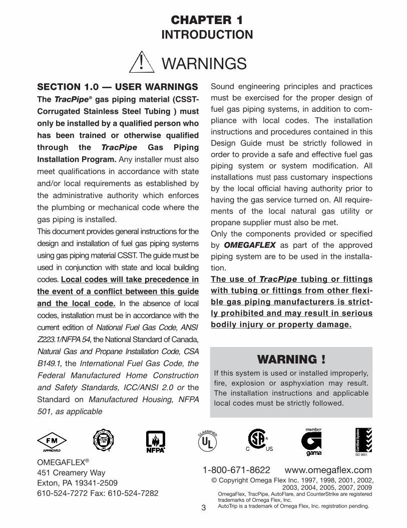
SECTION 1.0 — USER WARNINGSThe TracPipe® gas piping material (CSST-
Corrugated Stainless Steel Tubing ) must
only be installed by a qualified person who
has been trained or otherwise qualified
through the TracPipe Gas Piping
Installation Program. Any installer must also
meet qualifications in accordance with state
and/or local requirements as established by
the administrative authority which enforces
the plumbing or mechanical code where the
gas piping is installed.
This document provides general instructions for the
design and installation of fuel gas piping systems
using gas piping material CSST. The guide must be
used in conjunction with state and local building
codes. Local codes will take precedence in
the event of a conflict between this guide
and the local code. In the absence of local
codes, installation must be in accordance with the
current edition of National Fuel Gas Code, ANSI
Z223.1/NFPA 54, the National Standard of Canada,
Natural Gas and Propane Installation Code, CSA
B149.1, the International Fuel Gas Code, the
Federal Manufactured Home Construction
and Safety Standards, ICC/ANSI 2.0 or the
Standard on Manufactured Housing, NFPA
501, as applicable
Sound engineering principles and practicesmust be exercised for the proper design offuel gas piping systems, in addition to com-pliance with local codes. The installationinstructions and procedures contained in thisDesign Guide must be strictly followed inorder to provide a safe and effective fuel gaspiping system or system modification. Allinstallations must pass customary inspectionsby the local official having authority prior tohaving the gas service turned on. All require-ments of the local natural gas utility orpropane supplier must also be met. Only the components provided or specifiedby OMEGAFLEX as part of the approvedpiping system are to be used in the installa-tion. The use of TracPipe tubing or fittingswith tubing or fittings from other flexi-ble gas piping manufacturers is strict-ly prohibited and may result in seriousbodily injury or property damage.
WARNINGS!
OMEGAFLEX®
451 Creamery WayExton, PA 19341-2509610-524-7272 Fax: 610-524-7282
1-800-671-8622 www.omegaflex.com
CHAPTER 1INTRODUCTION
WARNING !If this system is used or installed improperly,fire, explosion or asphyxiation may result.The installation instructions and applicablelocal codes must be strictly followed.
© Copyright Omega Flex Inc. 1997, 1998, 2001, 2002,2003, 2004, 2005, 2007, 2009,
OmegaFlex, TracPipe, AutoFlare, and CounterStrike are registeredtrademarks of Omega Flex, Inc.AutoTrip is a trademark of Omega Flex, Inc. registration pending.3
111743_OmegaFlex_Txt:111743_OmegaFlex_Txt 5/28/09 11:56 AM Page 3
SECTION 1.1 — APPLICABLECODES AND STANDARDSREGIONAL / MODEL CODES LISTING CSSTAS AN ACCEPTABLE GAS PIPINGMATERIAL AS OF JULY 2005:
a. ANSI/IAS LC-1 • CSA 6.26 Standardb. CANADA-CSA B149.1 Natural Gas
and Propane Installation Codec. NFPA 54/ANSI Z 223.1 National Fuel
Gas Coded. ICBO-Uniform Mechanical Codee. BOCA-National Mechanical Codef. CABO-1 and 2 Family Dwelling Codeg. SBCCI-Standard Gas Codeh. ICC-International Mechanical Codei. IAPMO Listing FILE 3682j. IAPMO Listing FILE 4665 TracPipe
PS-II
WHILE EVERY EFFORT HAS BEEN MADE TO PREPARE THIS DOCUMENTIN ACCORDANCE WITH THE REGIONAL MODEL CODES IN EFFECT ATITS PRINTING, OMEGAFLEX CANNOT GUARANTEE THAT THE LOCAL ADMIN-ISTRATIVE AUTHORITY WILL ACCEPT THE MOST RECENT VERSION OFTHESE CODES.THE INSTALLER IS ULTIMATELY RESPONSIBLE TO DETERMINE SUITABILITYAND ACCEPTANCE OF ANY BUILDING COMPONENT, INCLUDING GASPIPING. OMEGAFLEX ASSUMES NO RESPONSIBILITY FOR MATERIALS ORLABOR FOR INSTALLATIONS MADE WITHOUT PRIOR DETERMINATION OFLOCAL CODE AUTHORITY ACCEPTANCE.
4
k. ICBO Evaluation Services ER-5412.l. Factory Mutual “Flexible Piping
Systems for Flammable Gases.”m. California Mechanical and Plumbing
Codesn. ICC-International Fuel Gas Codeo. NFPA 58 LP-Gas Codep. UPC-Uniform Plumbing Code 2003q. UL Through Penetration Firestop
Systems Classified (see Appendix A)r. Tested to Code Requirements per
ASTM E84 (UL 723)
This Design and Installation Guide has beenwritten in accordance with the most currentedition of ANSI LC1 CSA 6.26, Fuel GasPiping Systems using Corrugated StainlessSteel Tubing (CSST).
111743_OmegaFlex_Txt:111743_OmegaFlex_Txt 5/28/09 11:56 AM Page 4
5
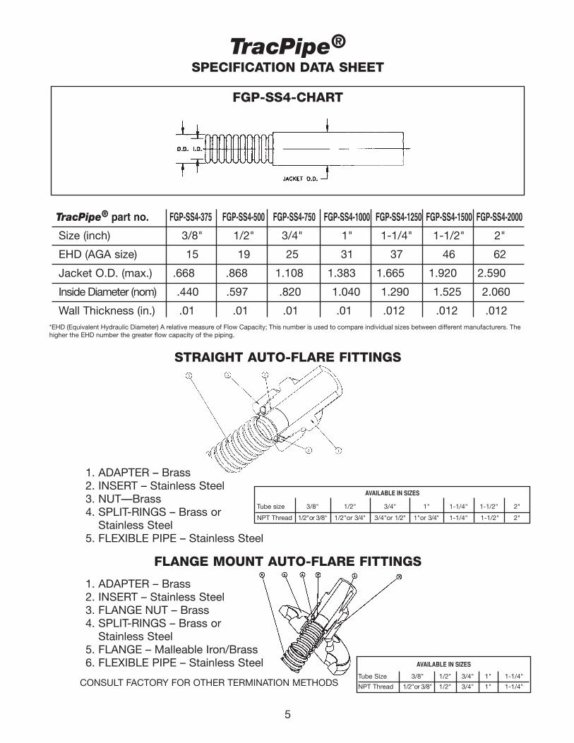
TracPipe®SPECIFICATION DATA SHEET
FGP-SS4-CHART
TracPipe® part no. FGP-SS4-375 FGP-SS4-500 FGP-SS4-750 FGP-SS4-1000 FGP-SS4-1250 FGP-SS4-1500 FGP-SS4-2000
Size (inch) 3/8" 1/2" 3/4" 1" 1-1/4" 1-1/2" 2"
EHD (AGA size) 15 19 25 31 37 46 62
Jacket O.D. (max.) .668 .868 1.108 1.383 1.665 1.920 2.590
Inside Diameter (nom) .440 .597 .820 1.040 1.290 1.525 2.060
Wall Thickness (in.) .01 .01 .01 .01 .012 .012 .012
STRAIGHT AUTO-FLARE FITTINGS
1. ADAPTER – Brass2. INSERT – Stainless Steel3. NUT—Brass4. SPLIT-RINGS – Brass or
Stainless Steel5. FLEXIBLE PIPE – Stainless Steel
FLANGE MOUNT AUTO-FLARE FITTINGS
1. ADAPTER – Brass2. INSERT – Stainless Steel3. FLANGE NUT – Brass4. SPLIT-RINGS – Brass or
Stainless Steel5. FLANGE – Malleable Iron/Brass6. FLEXIBLE PIPE – Stainless Steel
CONSULT FACTORY FOR OTHER TERMINATION METHODS
*EHD (Equivalent Hydraulic Diameter) A relative measure of Flow Capacity; This number is used to compare individual sizes between different manufacturers. Thehigher the EHD number the greater flow capacity of the piping.
AVAILABLE IN SIZES
Tube size 3/8" 1/2" 3/4" 1" 1-1/4" 1-1/2" 2"
NPT Thread 1/2"or 3/8" 1/2"or 3/4" 3/4"or 1/2" 1"or 3/4" 1-1/4" 1-1/2" 2"
AVAILABLE IN SIZES
Tube Size 3/8" 1/2" 3/4" 1" 1-1/4"
NPT Thread 1/2"or 3/8" 1/2" 3/4" 1" 1-1/4"
111743_OmegaFlex_Txt:111743_OmegaFlex_Txt 5/28/09 11:56 AM Page 5
6
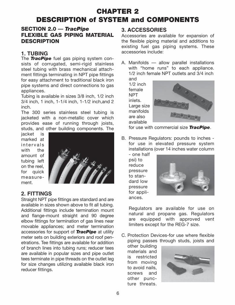
SECTION 2.0 — TracPipeFLEXIBLE GAS PIPING MATERIALDESCRIPTION
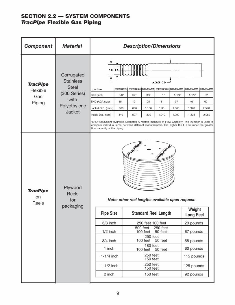
1. TUBINGThe TracPipe fuel gas piping system con-sists of corrugated, semi-rigid stainlesssteel tubing with brass mechanical attach-ment fittings terminating in NPT pipe fittingsfor easy attachment to traditional black ironpipe systems and direct connections to gasappliances.Tubing is available in sizes 3/8 inch, 1/2 inch3/4 inch, 1 inch, 1-1/4 inch, 1-1/2 inch,and 2inch. The 300 series stainless steel tubing is jacketed with a non-metallic cover whichprovides ease of running through joists,studs, and other building components. Thejacket ismarked ati n t e r v a l swith theamount oftubing lefton the reel,for quickmeasure-ment.
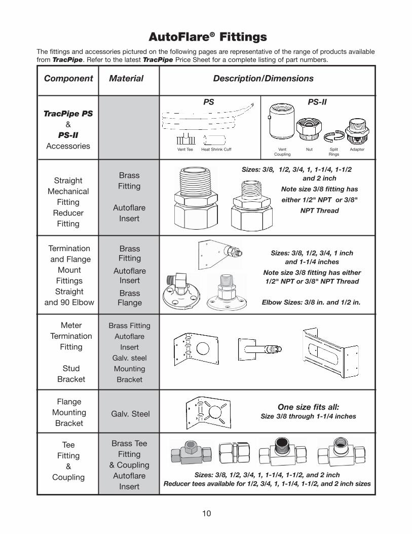
2. FITTINGSStraight NPT pipe fittings are standard and areavailable in sizes shown above to fit all tubing.Additional fittings include termination mountand flange-mount straight and 90 degreeelbow fittings for termination of gas lines nearmovable appliances; and meter terminationaccessories for support of TracPipe at utilitymeter sets on building exteriors and roof pen-etrations. Tee fittings are available for additionof branch lines into tubing runs; reducer teesare available in popular sizes and pipe outlettees terminate in pipe threads on the outlet legfor size changes utilizing available black ironreducer fittings.
3. ACCESSORIESAccessories are available for expansion ofthe flexible piping material and additions toexisting fuel gas piping systems. Theseaccessories include:
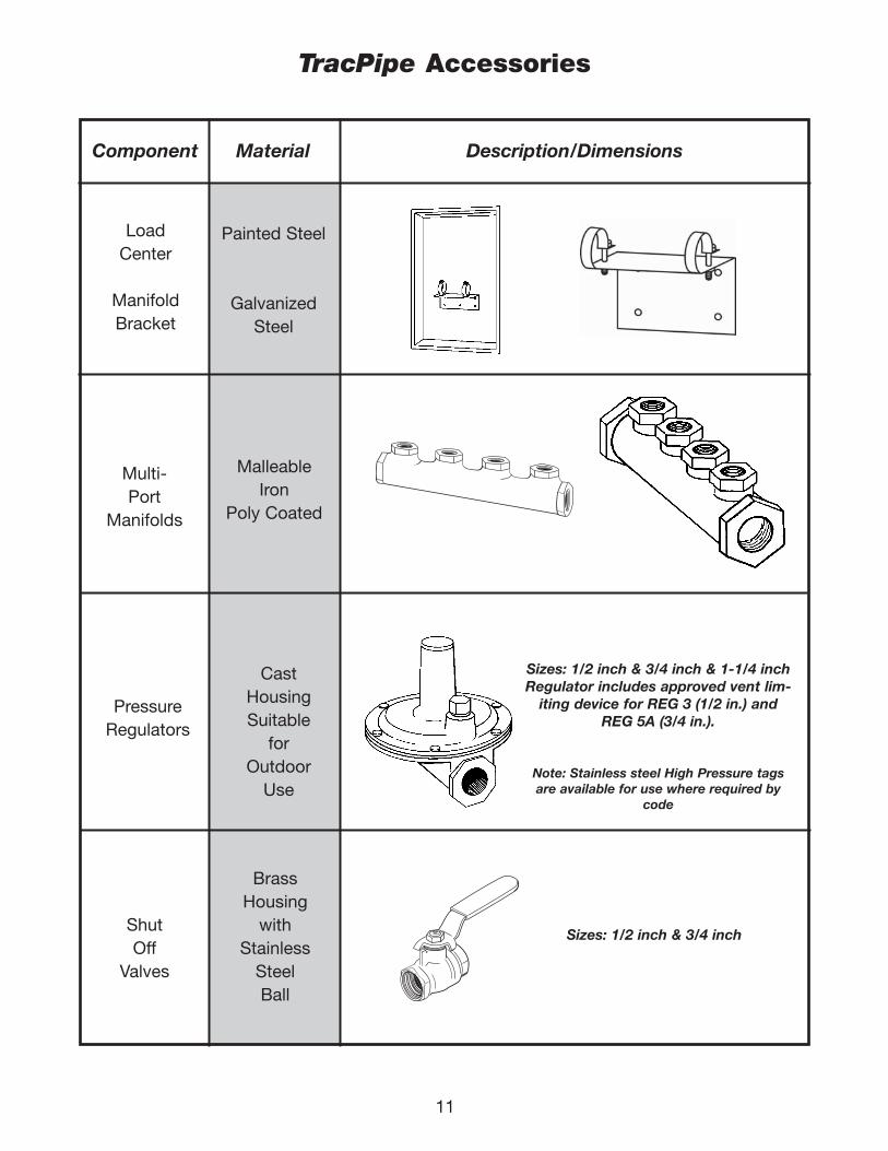
A. Manifolds — allow parallel installationswith “home runs” to each appliance.1/2 inch female NPT outlets and 3/4 inch and 1/2 inchfemaleNPTinlets.Large sizemanifoldsare alsoavailablefor use with commercial size TracPipe.
B. Pressure Regulators: pounds to inches -for use in elevated pressure systeminstallations (over 14 inches water column- one halfpsi) toreducepressureto stan-dard lowpressurefor appli-ances.
Regulators are available for use on natural and propane gas. Regulators are equipped with approved vent limiters except for the REG-7 size.
C. Protection Devices-for use where flexiblepiping passes through studs, joists andother buildingmaterials andis restrictedfrom movingto avoid nails,screws andother punc-ture threats.
CHAPTER 2DESCRIPTION of SYSTEM and COMPONENTS
111743_OmegaFlex_Txt:111743_OmegaFlex_Txt 5/28/09 11:56 AM Page 6
7
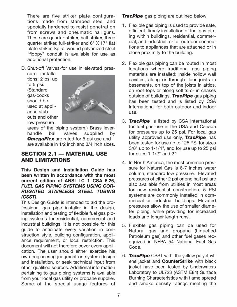
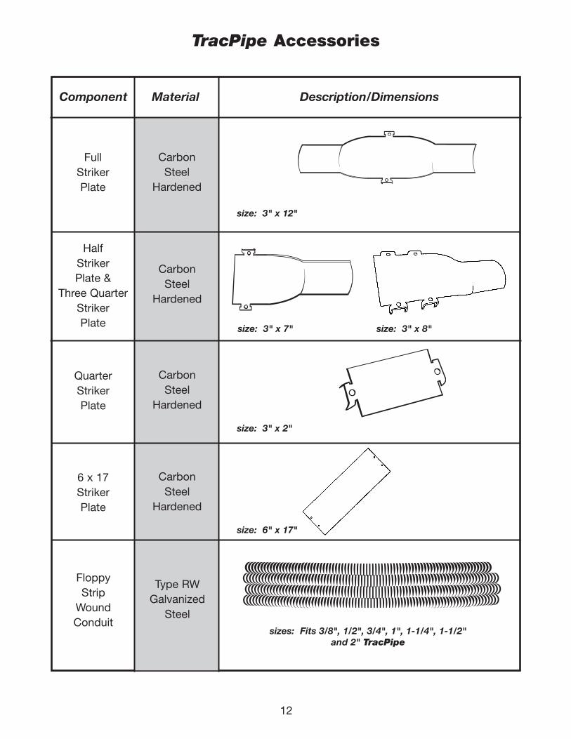
There are five striker plate configura-tions made from stamped steel andspecially hardened to resist penetrationfrom screws and pneumatic nail guns.These are quarter-striker, half striker, threequarter striker, full-striker and 6" X 17" flatplate striker. Spiral wound galvanized steel“floppy” conduit is available for use asadditional protection.
D. Shut-off Valves-for use in elevated pres-sure installa-tions: 2 psi upto 5 psi. (Standard gas-cocks should be used at appli-ance stub outs and otherlow pressure areas of the piping system.) Brass lever-handle ball valves supplied byOmegaFlex are rated for 5 psi use and are available in 1/2 inch and 3/4 inch sizes.
SECTION 2.1 — MATERIAL USEAND LIMITATIONS
This Design and Installation Guide hasbeen written in accordance with the mostcurrent edition of ANSI LC 1 CSA 6.26,FUEL GAS PIPING SYSTEMS USING COR-RUGATED STAINLESS STEEL TUBING(CSST).This Design Guide is intended to aid the pro-fessional gas pipe installer in the design,installation and testing of flexible fuel gas pip-ing systems for residential, commercial andindustrial buildings. It is not possible for thisguide to anticipate every variation in con-struction style, building configuration, appli-ance requirement, or local restriction. Thisdocument will not therefore cover every appli-cation. The user should either exercise hisown engineering judgment on system designand installation, or seek technical input fromother qualified sources. Additional informationpertaining to gas piping systems is availablefrom your local gas utility or propane supplier.Some of the special usage features of
TracPipe gas piping are outlined below:
1. Flexible gas piping is used to provide safe,efficient, timely installation of fuel gas pip-ing within buildings, residential, commer-cial, and industrial, or for outdoor connec-tions to appliances that are attached or inclose proximity to the building.
2. Flexible gas piping can be routed in mostlocations where traditional gas pipingmaterials are installed: inside hollow wallcavities, along or through floor joists inbasements, on top of the joists in attics,on roof tops or along soffits or in chasesoutside of buildings. TracPipe gas pipinghas been tested and is listed by CSAInternational for both outdoor and indooruse.
3. TracPipe is listed by CSA Internationalfor fuel gas use in the USA and Canadafor pressures up to 25 psi. For local gasutility approved use only, TracPipe hasbeen tested for use up to 125 PSI for sizes3/8" up to 1-1/4", and for use up to 25 psifor sizes 1-1/2" and 2".
4. In North America, the most common pres-sure for Natural Gas is 6-7 inches watercolumn, standard low pressure. Elevatedpressures of either 2 psi or one half psi arealso available from utilities in most areasfor new residential construction. 5 PSIsystems are commonly installed in com-mercial or industrial buildings. Elevatedpressures allow the use of smaller diame-ter piping, while providing for increasedloads and longer length runs.
5. Flexible gas piping can be used forNatural gas and propane (LiquefiedPetroleum gas) and other fuel gases rec-ognized in NFPA 54 National Fuel GasCode.
6. TracPipe CSST with the yellow polyethyl-ene jacket and CounterStrike with blackjacket have been tested by UnderwritersLaboratory to UL723 (ASTM E84) SurfaceBurning Characteristics with flame spreadand smoke density ratings meeting the
111743_OmegaFlex_Txt:111743_OmegaFlex_Txt 5/28/09 11:57 AM Page 7
8
requirements of ANSI/CSA LC-1 for use inair ducts and plenums. It is mandatory,however, to follow fire and building coderequirements in all installations.
7. For underground or under slab burial theflexible gas piping run must be encased ina sleeve of polyethylene, or otherapproved water resistant material. SeeSection 4.9, Underground Installations.Sleeved runs under concrete slabsbeneath buildings must be installed asrequired by local codes. Most codesrequire venting of the sleeves under build-ings to the outdoors. This can be accom-plished using Pre-sleeved TracPipe PSor PS-II with available accessories.
8. Flexible gas piping can be used in con-junction with steel pipe (black iron or gal-vanized) in either new construction or ren-ovation and replacement piping installa-tions. All TracPipe fittings terminate instandard NPT male or female pipe threadsto interface with appliances, valves,unions and couplings.
9. For retrofit installations, TracPipe can besnaked through hollow wall cavities with-out major restoration as is typical whenrunning rigid pipe through existing con-struction. The replacement or addition ofgas appliances, fireplaces, and gas logs isgreatly facilitated with flexible piping onreels requiring no special tooling or oilythreading equipment.
10. TracPipe gas piping can be run directlyto the shut off valves of most fixed appli-ances without installing an applianceconnector. For moveable appliancessuch as ranges or dryers, the use of anapproved flexible appliance connector isrequired in most jurisdictions. TracPipecannot be substituted as a connector forthis use when the appliance is free tomove for cleaning, etc.
11. TracPipe AutoFlare® fittings have beentested by CSA International (formerly theAmerican Gas Association Laboratories )and are listed for use in concealed loca-tions as defined in NFPA 54 National FuelGas Code, The Uniform Plumbing Code,and The International Fuel Gas Code.This facilitates installation of the keyvalves required for gas fireplaces in manyjurisdictions. Concealed fittings are alsodesirable when adding tees for branchruns in series configurations and in otherinstallation situations where locating aTracPipe fitting in an accessible locationis not practical.
111743_OmegaFlex_Txt:111743_OmegaFlex_Txt 5/28/09 11:57 AM Page 8
9
SECTION 2.2 — SYSTEM COMPONENTSTracPipe Flexible Gas Piping
Component Material Description/Dimensions
TracPipeFlexible
GasPiping
CorrugatedStainless
Steel(300 Series)
withPolyethylene
Jacket
TracPipeon
Reels
PlywoodReels
forpackaging
Pipe Size Standard Reel Length
3/8 inch 250 feet 100 feet 29 pounds
1/2 inch 87 pounds
3/4 inch 55 pounds
1 inch 180 feet 60 pounds
1-1/4 inch 115 pounds
1-1/2 inch 125 pounds
2 inch 150 feet 92 pounds
part no. FGP-SS4-375 FGP-SS4-500 FGP-SS4-750 FGP-SS4-1000 FGP-SS4-1250 FGP-SS4-1500 FGP-SS4-2000
Size (inch) 3/8" 1/2" 3/4" 1" 1-1/4" 1-1/2" 2"
EHD (AGA size) 15 19 25 31 37 46 62
Jacket O.D. (max.) .668 .868 1.108 1.38 1.665 1.920 2.590
Inside Dia. (nom) .440 .597 .820 1.040 1.290 1.525 2.060
*EHD (Equivalent Hydraulic Diameter) A relative measure of Flow Capacity; This number is used tocompare individual sizes between different manufacturers. The higher the EHD number the greaterflow capacity of the piping.
Note: other reel lengths available upon request.
500 feet 250 feet100 feet 50 feet
250 feet100 feet 50 feet
WeightLong Reel
250 feet150 feet250 feet150 feet
®
®
180 feet100 feet 50 feet
111743_OmegaFlex_Txt:111743_OmegaFlex_Txt 5/28/09 11:57 AM Page 9
10
AutoFlare® Fittings
Component Material Description/Dimensions
The fittings and accessories pictured on the following pages are representative of the range of products availablefrom TracPipe. Refer to the latest TracPipe Price Sheet for a complete listing of part numbers.
StraightMechanical
FittingReducerFitting
BrassFitting
AutoflareInsert
Terminationand Flange
MountFittingsStraight
and 90 Elbow
BrassFitting
AutoflareInsert
BrassFlange
MeterTermination
Fitting
StudBracket
FlangeMountingBracket
Brass Fitting
Autoflare
Insert
Galv. steel
Mounting
Bracket
Galv. Steel
TeeFitting
&Coupling
Brass TeeFitting
& CouplingAutoflare
Insert
Elbow Sizes: 3/8 in. and 1/2 in.
One size fits all:Size 3/8 through 1-1/4 inches
Sizes: 3/8, 1/2, 3/4, 1, 1-1/4, 1-1/2and 2 inch
Note size 3/8 fitting has
either 1/2" NPT or 3/8"
NPT Thread
Sizes: 3/8, 1/2, 3/4, 1 inchand 1-1/4 inches
Note size 3/8 fitting has either1/2" NPT or 3/8" NPT Thread
Sizes: 3/8, 1/2, 3/4, 1, 1-1/4, 1-1/2, and 2 inchReducer tees available for 1/2, 3/4, 1, 1-1/4, 1-1/2, and 2 inch sizes
TracPipe PS&
PS-IIAccessories Vent Tee Heat Shrink Cuff
PS PS-II
Vent Nut Split AdapterCoupling Rings
111743_OmegaFlex_Txt:111743_OmegaFlex_Txt 5/28/09 11:57 AM Page 10
11
TracPipe Accessories
Component Material Description/Dimensions
Multi-Port
Manifolds
LoadCenter
ManifoldBracket
MalleableIron
Poly Coated
PressureRegulators
CastHousingSuitable
forOutdoor
Use
ShutOff
Valves
BrassHousing
withStainless
SteelBall
Sizes: 1/2 inch & 3/4 inch & 1-1/4 inchRegulator includes approved vent lim-
iting device for REG 3 (1/2 in.) and REG 5A (3/4 in.).
Note: Stainless steel High Pressure tagsare available for use where required by
code
Sizes: 1/2 inch & 3/4 inch
Painted Steel
GalvanizedSteel
111743_OmegaFlex_Txt:111743_OmegaFlex_Txt 5/28/09 11:57 AM Page 11
12
TracPipe Accessories
Component Material Description/Dimensions
FullStrikerPlate
CarbonSteel
Hardened
HalfStrikerPlate &
Three QuarterStrikerPlate
CarbonSteel
Hardened
QuarterStrikerPlate
CarbonSteel
Hardened
FloppyStrip
WoundConduit
Type RWGalvanized
Steel
size: 3" x 12"
size: 3" x 7" size: 3" x 8"
size: 3" x 2"
6 x 17StrikerPlate
CarbonSteel
Hardened
size: 6" x 17"
sizes: Fits 3/8", 1/2", 3/4", 1", 1-1/4", 1-1/2"and 2" TracPipe
111743_OmegaFlex_Txt:111743_OmegaFlex_Txt 5/28/09 11:57 AM Page 12
13
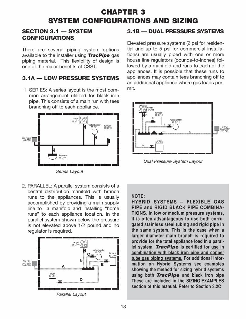
SECTION 3.1 — SYSTEM CONFIGURATIONS
There are several piping system optionsavailable to the installer using TracPipe gaspiping material. This flexibility of design isone of the major benefits of CSST.
3.1A — LOW PRESSURE SYSTEMS
1. SERIES: A series layout is the most com-mon arrangement utilized for black ironpipe. This consists of a main run with teesbranching off to each appliance.
2. PARALLEL: A parallel system consists of acentral distribution manifold with branchruns to the appliances. This is usuallyaccomplished by providing a main supplyline to a manifold and installing “homeruns” to each appliance location. In theparallel system shown below the pressureis not elevated above 1/2 pound and noregulator is required.
3.1B — DUAL PRESSURE SYSTEMS
Elevated pressure systems (2 psi for residen-tial and up to 5 p si for commercial installa-tions) are usually piped with one or morehouse line regulators (pounds-to-inches) fol-lowed by a manifold and runs to each of theappliances. It is possible that these runs toappliances may contain tees branching off toan additional appliance where gas loads per-mit.
range50 CFH
water heater30 CFH
furnace60 CFH
fireplace18 CFH
gas meter163 CFH
2 PSIgas meter205 CFH
B
A
C
range55 CFH
water heater40 CFH
dryer30 CFH
furnace80 CFHE
D
Dual Pressure System Layout
range55 CFH
1/2 PSIgas meter205 CFH
water heater40 CFH
dryer30 CFH
furnace80 CFH
A
BC
D
E
NOTE:HYBRID SYSTEMS – FLEXIBLE GASPIPE and RIGID BLACK PIPE COMBINA-TIONS. In low or medium pressure systems,it is often advantageous to use both corru-gated stainless steel tubing and rigid pipe inthe same system. This is the case when alarger diameter main branch is required toprovide for the total appliance load in a paral-lel system. TracPipe is certified for use incombination with black iron pipe and coppertube gas piping systems. For additional infor-mation on Hybrid Systems see examplesshowing the method for sizing hybrid systemsusing both TracPipe and black iron pipeThese are included in the SIZING EXAMPLESsection of this manual. Refer to Section 3.2C
Parallel Layout
Series Layout
CHAPTER 3SYSTEM CONFIGURATIONS AND SIZING
111743_OmegaFlex_Txt:111743_OmegaFlex_Txt 5/28/09 11:57 AM Page 13
SECTION 3.1C — SYSTEM DESIGN
1. Prepare a sketch or layout of the gas pip-ing system you are about to install. Theinformation you will need is the location ofeach appliance, the point of delivery(location of utility meter or second stageLP regulator), appliance load demands,and possible pipe routing locations. Theload demand data is usually available onthe appliance manufacturer’s nameplate,or can be provided by the builder.
2. Determine local piping restrictions prior toinstalling flexible gas piping. The majorcode bodies in North America have writtenCorrugated Stainless Steel Tubing into thelatest revisions of their mechanical codes,but local and state adoption of thesecodes often lags behind. CONFIRM THATTHE LOCAL CODE AUTHORITY HASACCEPTED THE USE OF FLEXIBLE GASPIPING. Your TracPipe distributor shouldbe able to provide that information butconfirmation by the installer should bemade where there is a question.
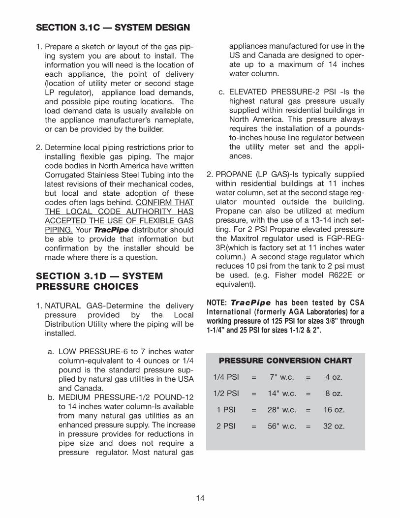
SECTION 3.1D — SYSTEM PRESSURE CHOICES
1. NATURAL GAS-Determine the deliverypressure provided by the LocalDistribution Utility where the piping will beinstalled.
a. LOW PRESSURE-6 to 7 inches watercolumn-equivalent to 4 ounces or 1/4pound is the standard pressure sup-plied by natural gas utilities in the USAand Canada.
b. MEDIUM PRESSURE-1/2 POUND-12to 14 inches water column-Is availablefrom many natural gas utilities as anenhanced pressure supply. The increasein pressure provides for reductions inpipe size and does not require a pressure regulator. Most natural gas
appliances manufactured for use in theUS and Canada are designed to oper-ate up to a maximum of 14 incheswater column.
c. ELEVATED PRESSURE-2 PSI -Is thehighest natural gas pressure usuallysupplied within residential buildings inNorth America. This pressure alwaysrequires the installation of a pounds-to-inches house line regulator betweenthe utility meter set and the appli-ances.
2. PROPANE (LP GAS)-Is typically suppliedwithin residential buildings at 11 incheswater column, set at the second stage reg-ulator mounted outside the building.Propane can also be utilized at mediumpressure, with the use of a 13-14 inch set-ting. For 2 PSI Propane elevated pressurethe Maxitrol regulator used is FGP-REG-3P.(which is factory set at 11 inches watercolumn.) A second stage regulator whichreduces 10 psi from the tank to 2 psi mustbe used. (e.g. Fisher model R622E orequivalent).
NOTE: TracPipe has been tested by CSAInternational (formerly AGA Laboratories) for aworking pressure of 125 PSI for sizes 3/8" through1-1/4" and 25 PSI for sizes 1-1/2 & 2".
PRESSURE CONVERSION CHART
1/4 PSI = 7" w.c. = 4 oz.
1/2 PSI = 14" w.c. = 8 oz.
1 PSI = 28" w.c. = 16 oz.
2 PSI = 56" w.c. = 32 oz.
14
111743_OmegaFlex_Txt:111743_OmegaFlex_Txt 5/28/09 11:57 AM Page 14
15
SECTION 3.2 SIZING METHODS and EXAMPLESSECTION 3.2A — USE OF SIZINGTABLES
This Chapter includes flexible gas piping siz-ing procedures for both low pressure and ele-vated pressure systems. Every piping systemintroduces pressure loss to the fluid flowingwithin. The amount of loss depends on thepiping size and the gas flow, expressed incubic feet per hour (and converted to BTU’s).The object of the sizing exercise is to deter-mine the smallest size piping which will intro-duce the allowed pressure loss or drop with-in the length of piping required. Sizing Tables(Capacity Charts) provide the maximum flowcapacity for a given length of run for eachpipe size. A different sizing table is used foreach system pressure and pressure dropcombination.
1. The low pressure series system (standardarrangement) is sized in the same way as aconventional low pressure black iron pipesystem using TracPipe sizing tables ortables found in National Fuel Gas CodeNFPA 54. This method is known as the“Branch Length Method”. Pressure drop ina low pressure system is usually limited to1/2 inch water column over the system.
2. Elevated pressure systems incorporate twooperating pressures downstream of the util-ity meter set. The first pressure, set by theservice regulator at the meter, is usually 2PSI. This part of the system is sized sepa-rately and ends at the pounds-to-inches reg-ulator. The allowable pressure loss for thispart of the system must be added to theeffect of the regulator to determine the avail-able pressure at the regulator outlet. Thechart in Section 4.8B shows pressure lossesfor maximum loads through the regulator.
3. For a 2 PSI system, the proper drop is usu-ally 1 PSI for this part of the system; thisallows for the approximate 3/4 PSI regula-tor drop downstream and provides the 1/4PSI (6-7 inches w.c.) necessary for appli-ances. The regulator reduces the pressurefrom pounds to 8 inches water column.
This part of the system is sized the sameas a low pressure system, except that aspecial table N-3 is used allowing 3 inchesof water column drop. These lines are typ-ically sized for only one appliance loadinstalled as a “home run” from the mani-fold.
SECTION 3.2B — SIZING EXAMPLESBRANCH LENGTH METHOD
To size each of the following systems, deter-mine the required size for each section andoutlet. To size each section of the system,determine both the total gas load for all appli-ances and the maximum distance (longestlength) in which a particular section deliversgas.
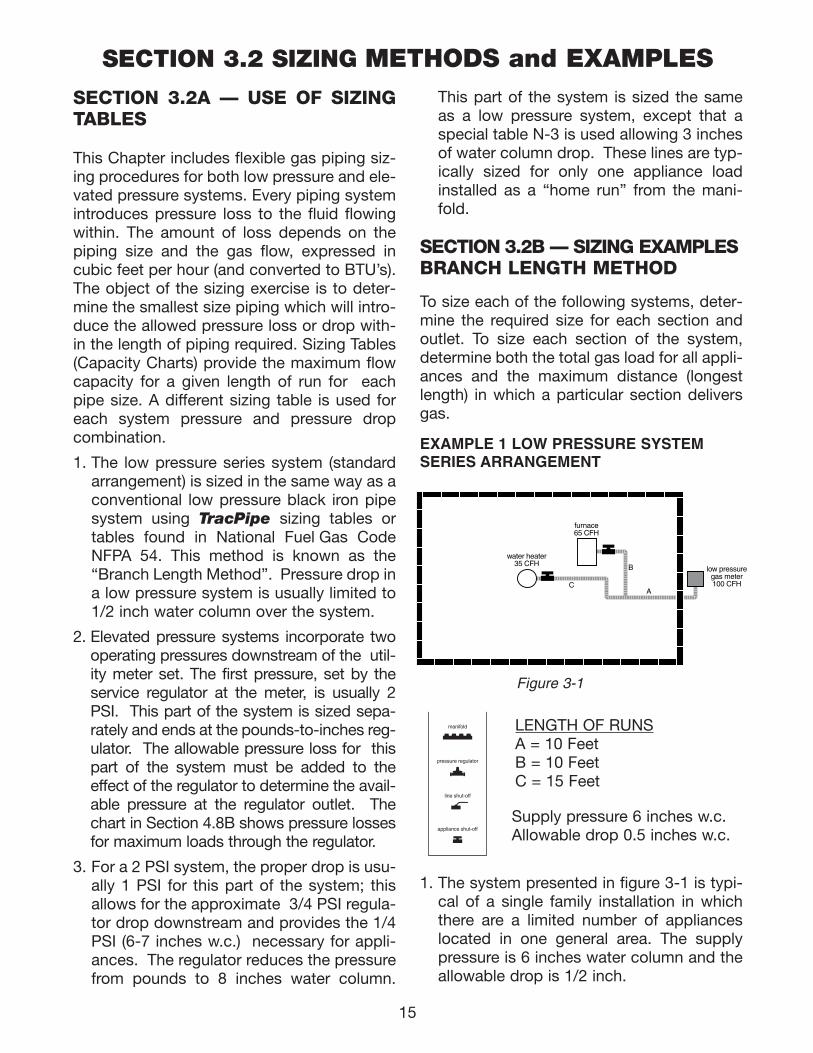
EXAMPLE 1 LOW PRESSURE SYSTEMSERIES ARRANGEMENT
1. The system presented in figure 3-1 is typi-cal of a single family installation in whichthere are a limited number of applianceslocated in one general area. The supplypressure is 6 inches water column and theallowable drop is 1/2 inch.
low pressuregas meter100 CFH
water heater35 CFH
furnace65 CFH
B
AC
LENGTH OF RUNSA = 10 Feet B = 10 Feet C = 15 Feet
manifold
pressure regulator
line shut-off
appliance shut-off
Figure 3-1
Supply pressure 6 inches w.c.Allowable drop 0.5 inches w.c.
111743_OmegaFlex_Txt:111743_OmegaFlex_Txt 5/28/09 11:57 AM Page 15
16
2. To size section A, determine the longestrun from the meter that includes section Aand the total gas load it must deliver:
• Meter to Furnace is 20 ft. (A+B)
• Meter to Water Heater is 25 ft. (A+C). This is the longest run.
• Determine the maximum load trans-ported by Section A
• Furnace plus Water Heater = 100 cfh(100,000 BTU)
• Select Table N-1 “Low Pressure 6inches- 1/2 inch w.c. drop”
• Using the longest run method, selectthe column showing the measuredlength, or the next longest length if thetable does not give the exact length.Referring to table N-1 the column for 25feet of piping shows that sizes 3/8 and1/2 are too small and the next availablesize is 3/4 supplying 157 cfh.
• The correct size is 3/4".
3. To size Section B, determine the length ofrun from the meter to the Furnace and theload delivered:
• Length is 20 ft (A+B) and load is 65 cfh (65,000 BTU)
• Table N-1 shows that size 1/2" supplies70 cfh
• The correct size is 1/2".
4. To size Section C, determine the length ofrun from the meter to the Water Heater andthe load delivered:
• Length is 25 ft (A+C) and load is 35 cfh(35,000 BTU)
• Table N-1 shows that size 1/2" isrequired, because size 3/8" only sup-plies 29 cfh (29,000 BTU)
• The correct size is 1/2"
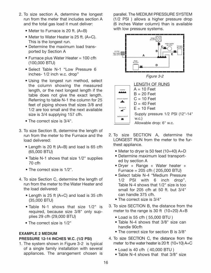
EXAMPLE 2 MEDIUMPRESSURE 12-14 INCHES W.C. (1/2 PSI)1. The system shown in Figure 3-2 is typical
of a single family installation with severalappliances. The arrangement chosen is
parallel. The MEDIUM PRESSURE SYSTEM(1/2 PSI ) allows a higher pressure drop (6 inches Water column) than is availablewith low pressure systems.
2. To size SECTION A, determine theLONGEST RUN from the meter to the fur-thest appliance.
• Meter to dryer is 50 feet (10+40) A+D• Determine maximum load transport-
ed by section A• Dryer + Range + Water heater +
Furnace = 205 cfh ( 205,000 BTU)• Select table N-4 “Medium Pressure
1/2 PSI with 6 inch drop”.Table N-4 shows that 1/2" size is toosmall for 205 cfh at 50 ft. but 3/4"can handle 375 cfh.
• The correct size is 3/4"
3. To size SECTION B, the distance from themeter to the range is 30 ft (10+20) A+B
• Load is 55 cfh ( 55,000 BTU )• Table N-4 shows that 3/8" size can
handle 90cfh• The correct size for section B is 3/8"
4. To size SECTION C, the distance from themeter to the water heater is 20 ft (10+10) A+C
• Load is 40 cfh ( 40,000 BTU )• Table N-4 shows that that 3/8" size
Supply pressure 1/2 PSI (12"-14"w.c.)Allowable drop: 6" w.c.
manifold
pressure regulator
line shut-off
appliance shut-off
LENGTH OF RUNSA = 10 Feet B = 20 Feet C = 10 FeetD = 40 FeetE = 10 Feet
range55 CFH
1/2 PSIgas meter205 CFH
water heater40 CFH
dryer30 CFH
furnace80 CFH
A
BC
D
E
Figure 3-2
111743_OmegaFlex_Txt:111743_OmegaFlex_Txt 6/5/09 2:04 PM Page 16
can handle 112cfh• The correct size for section C is 3/8"
5. To size SECTION D, the distance from themeter to the dryer is 50 ft (10+40) A+D
• Load is 30 cfh ( 30,000 BTU )• Table N-4 shows that that 3/8" size
can handle 69cfh at 50 feet• The correct size for section D is 3/8"
6. To size SECTION E, the distance from themeter to the furnace is 20 ft (10+10) A+E
• Load is 80 cfh ( 80,000 BTU )• Table N-4 shows that that 3/8" size
can handle 112cfh at 20 feet• The correct size for section E is 3/8"
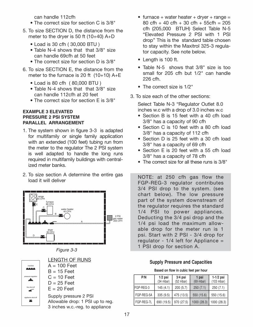
EXAMPLE 3 ELEVATEDPRESSURE 2 PSI SYSTEMPARALLEL ARRANGEMENT
1. The system shown in figure 3-3 is adaptedfor multifamily or single family applicationwith an extended (100 feet) tubing run fromthe meter to the regulator The 2 PSI systemis well adapted to handle the long runsrequired in multifamily buildings with central-ized meter banks.
2. To size section A determine the entire gasload it will deliver
• furnace + water heater + dryer + range =80 cfh + 40 cfh + 30 cfh + 55cfh = 205cfh (205,000 BTUH) Select Table N-5“Elevated Pressure 2 PSI with 1 PSIdrop’’ This is the standard table chosento stay within the Maxitrol 325-3 regula-tor capacity. See note below.
• Length is 100 ft.
• Table N-5 shows that 3/8" size is toosmall for 205 cfh but 1/2" can handle226 cfh.
• The correct size is 1/2"
3. To size each of the other sections:
Select Table N-3 “Regulator Outlet 8.0inches w.c with a drop of 3.0 inches w.c• Section B is 15 feet with a 40 cfh load
3/8" has a capacity of 90 cfh• Section C is 10 feet with a 80 cfh load
3/8" has a capacity of 112 cfh• Section D is 25 feet with a 30 cfh load
3/8" has a capacity of 69 cfh• Section E is 20 feet with a 55 cfh load
3/8" has a capacity of 78 cfh• The correct size for all these runs is 3/8"
2 PSIgas meter205 CFH
B
A
C
range55 CFH
water heater40 CFH
dryer30 CFH
furnace80 CFHE
D
Figure 3-3
manifold
pressure regulator
line shut-off
appliance shut-off
LENGTH OF RUNSA = 100 Feet B = 15 Feet C = 10 FeetD = 25 FeetE = 20 Feet
Supply pressure 2 PSIAllowable drop: 1 PSI up to reg.3 inches w.c.-reg. to appliance
NOTE: at 250 cfh gas flow theFGP-REG-3 regulator contributes3/4 PSI drop to the system. (seechart below). The low pressurepart of the system downstream ofthe regulator requires the standard1/4 PSI to power appliances.Deducting the 3/4 psi drop and the1/4 psi load the maximum allow-able drop for the meter run is 1psi. Start with 2 PSI - 3/4 drop forregulator - 1/4 left for Appliance =1 PSI drop for section A.
17
Supply Pressure and Capacities
Based on flow in cubic feet per hour
P/N 1/2 psi 3/4 psi 1 psi 1-1/2 psi (34 mbar) (52 mbar) (69 mbar) (103 mbar)
FGP-REG-3 145 (4.1) 200 (5.7) 250 (7.1) 250 (7.1)
FGP-REG-5A 335 (9.5) 475 (13.5) 550 (15.6) 550 (15.6)
FGP-REG-7L 690 (19.5) 970 (27.5) 1000 (28.3) 1000 (28.3)
111743_OmegaFlex_Txt:111743_OmegaFlex_Txt 5/28/09 11:57 AM Page 17
18
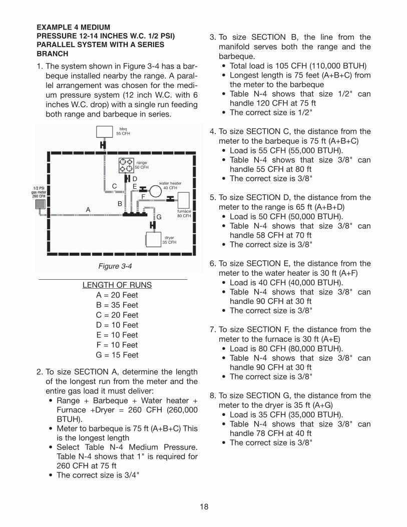
EXAMPLE 4 MEDIUM PRESSURE 12-14 INCHES W.C. 1/2 PSI) PARALLEL SYSTEM WITH A SERIESBRANCH
1. The system shown in Figure 3-4 has a bar-beque installed nearby the range. A paral-lel arrangement was chosen for the medi-um pressure system (12 inch W.C. with 6inches W.C. drop) with a single run feedingboth range and barbeque in series.
LENGTH OF RUNS
A = 20 FeetB = 35 FeetC = 20 FeetD = 10 FeetE = 10 FeetF = 10 FeetG = 15 Feet
2. To size SECTION A, determine the lengthof the longest run from the meter and theentire gas load it must deliver: • Range + Barbeque + Water heater +
Furnace +Dryer = 260 CFH (260,000BTUH).
• Meter to barbeque is 75 ft (A+B+C) Thisis the longest length
• Select Table N-4 Medium Pressure.Table N-4 shows that 1" is required for260 CFH at 75 ft
• The correct size is 3/4"
3. To size SECTION B, the line from the manifold serves both the range and thebarbeque. • Total load is 105 CFH (110,000 BTUH)• Longest length is 75 feet (A+B+C) from
the meter to the barbeque• Table N-4 shows that size 1/2" can
handle 120 CFH at 75 ft• The correct size is 1/2"
4. To size SECTION C, the distance from themeter to the barbeque is 75 ft (A+B+C) • Load is 55 CFH (55,000 BTUH).• Table N-4 shows that size 3/8" can
handle 55 CFH at 80 ft• The correct size is 3/8"
5. To size SECTION D, the distance from themeter to the range is 65 ft (A+B+D) • Load is 50 CFH (50,000 BTUH).• Table N-4 shows that size 3/8" can
handle 58 CFH at 70 ft• The correct size is 3/8"
6. To size SECTION E, the distance from themeter to the water heater is 30 ft (A+F) • Load is 40 CFH (40,000 BTUH).• Table N-4 shows that size 3/8" can
handle 90 CFH at 30 ft• The correct size is 3/8"
7. To size SECTION F, the distance from themeter to the furnace is 30 ft (A+E) • Load is 80 CFH (80,000 BTUH).• Table N-4 shows that size 3/8" can
handle 90 CFH at 30 ft• The correct size is 3/8"
8. To size SECTION G, the distance from themeter to the dryer is 35 ft (A+G) • Load is 35 CFH (35,000 BTUH).• Table N-4 shows that size 3/8" can
handle 78 CFH at 40 ft• The correct size is 3/8"
Figure 3-4
AB
CDE
F
G
1/2 PSIgas meter260 CFH
bbq 55 CFH
range 50 CFH
water heater40 CFH
furnace80 CFH
dryer 35 CFH
111743_OmegaFlex_Txt:111743_OmegaFlex_Txt 6/5/09 2:05 PM Page 18
19
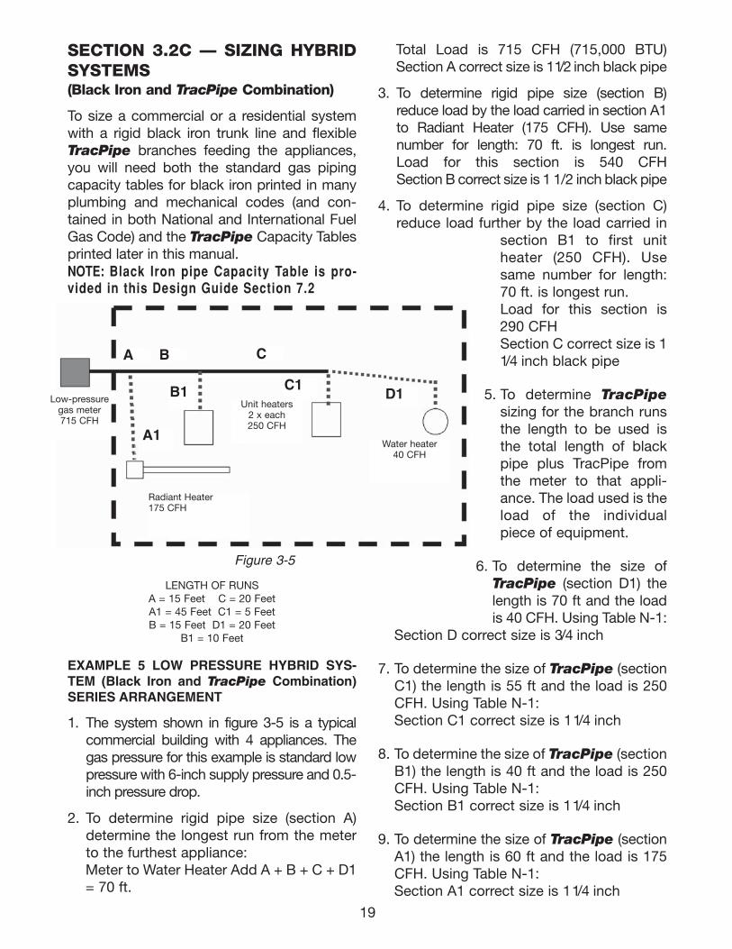
SECTION 3.2C — SIZING HYBRID SYSTEMS (Black Iron and TracPipe Combination)
To size a commercial or a residential systemwith a rigid black iron trunk line and flexibleTracPipe branches feeding the appliances,you will need both the standard gas pipingcapacity tables for black iron printed in manyplumbing and mechanical codes (and con-tained in both National and International FuelGas Code) and the TracPipe Capacity Tablesprinted later in this manual.NOTE: Black Iron pipe Capacity Table is pro-vided in this Design Guide Section 7.2
LENGTH OF RUNSA = 15 Feet C = 20 FeetA1 = 45 Feet C1 = 5 FeetB = 15 Feet D1 = 20 Feet
B1 = 10 Feet
EXAMPLE 5 LOW PRESSURE HYBRID SYS-TEM (Black Iron and TracPipe Combination)SERIES ARRANGEMENT
1. The system shown in figure 3-5 is a typicalcommercial building with 4 appliances. Thegas pressure for this example is standard lowpressure with 6-inch supply pressure and 0.5-inch pressure drop.
2. To determine rigid pipe size (section A)determine the longest run from the meterto the furthest appliance:Meter to Water Heater Add A + B + C + D1= 70 ft.
Total Load is 715 CFH (715,000 BTU)Section A correct size is 11/2 inch black pipe
3. To determine rigid pipe size (section B)reduce load by the load carried in section A1to Radiant Heater (175 CFH). Use samenumber for length: 70 ft. is longest run.Load for this section is 540 CFHSection B correct size is 1 1/2 inch black pipe
4. To determine rigid pipe size (section C)reduce load further by the load carried in
section B1 to first unitheater (250 CFH). Usesame number for length:70 ft. is longest run.Load for this section is290 CFHSection C correct size is 11/4 inch black pipe
5. To determine TracPipesizing for the branch runsthe length to be used isthe total length of blackpipe plus TracPipe fromthe meter to that appli-ance. The load used is theload of the individualpiece of equipment.
6. To determine the size ofTracPipe (section D1) thelength is 70 ft and the loadis 40 CFH. Using Table N-1:
Section D correct size is 3/4 inch
7. To determine the size of TracPipe (sectionC1) the length is 55 ft and the load is 250CFH. Using Table N-1:Section C1 correct size is 11/4 inch
8. To determine the size of TracPipe (sectionB1) the length is 40 ft and the load is 250CFH. Using Table N-1:Section B1 correct size is 11/4 inch
9. To determine the size of TracPipe (sectionA1) the length is 60 ft and the load is 175CFH. Using Table N-1:Section A1 correct size is 11/4 inch
Low-pressuregas meter715 CFH
Unit heaters2 x each250 CFH
Radiant Heater175 CFH
A B C
C1B1
A1Water heater
40 CFH
Figure 3-5
D1
111743_OmegaFlex_Txt:111743_OmegaFlex_Txt 5/28/09 11:57 AM Page 19
20
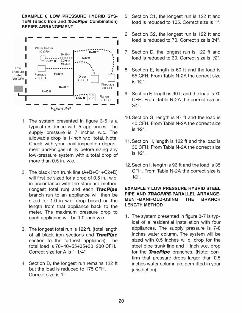
EXAMPLE 6 LOW PRESSURE HYBRID SYS-TEM (Black Iron and TracPipe Combination)SERIES ARRANGEMENT
1. The system presented in figure 3-6 is atypical residence with 5 appliances. Thesupply pressure is 7 inches w.c. Theallowable drop is 1-inch w.c. total. Note:Check with your local inspection depart-ment and/or gas utility before sizing anylow-pressure system with a total drop ofmore than 0.5 in. w.c.
2. The black iron trunk line (A+B+C1+C2+D)will first be sized for a drop of 0.5 in., w.c.in accordance with the standard method(longest total run) and each TracPipebranch run to an appliance will then besized for 1.0 in w.c. drop based on thelength from that appliance back to themeter. The maximum pressure drop toeach appliance will be 1.0-inch w.c.
3. The longest total run is 122 ft. (total lengthof all black iron sections and TracPipesection to the furthest appliance). Thetotal load is 70+40+55+35+30=230 CFH.Correct size for A is 1-1/4"
4. Section B, the longest run remains 122 ftbut the load is reduced to 175 CFH.Correct size is 1".
5. Section C1, the longest run is 122 ft andload is reduced to 105. Correct size is 1".
6. Section C2, the longest run is 122 ft andload is reduced to 70. Correct size is 3/4".
7. Section D, the longest run is 122 ft andload is reduced to 30. Correct size is 1/2".
8. Section E, length is 60 ft and the load is55 CFH. From Table N-2A the correct sizeis 1/2".
9. Section F, length is 90 ft and the load is 70CFH. From Table N-2A the correct size is3/4".
10.Section G, length is 97 ft and the load is40 CFH. From Table N-2A the correct sizeis 1/2".
11.Section H, length is 122 ft and the load is30 CFH. From Table N-2A the correct sizeis 1/2".
12.Section I, length is 96 ft and the load is 35CFH. From Table N-2A the correct size is1/2".
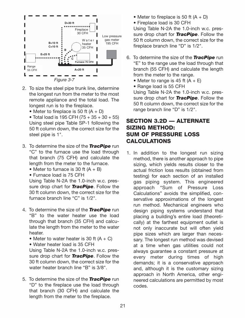
EXAMPLE 7 LOW PRESSURE HYBRID STEELPIPE AND TRACPIPE-PARALLEL ARRANGE-MENT-MANIFOLD-USING THE BRANCHLENGTH METHOD
1. The system presented in figure 3-7 is typ-ical of a residential installation with fourappliances. The supply pressure is 7-8inches water column. The system will besized with 0.5 inches w. c. drop for thesteel pipe trunk line and 1 inch w.c. dropfor the TracPipe branches. (Note: con-firm that pressure drops larger than 0.5inches water column are permitted in yourjurisdiction)
Low pressure
meter230 CFH
Water heater40 CFH
Dryer 35 CFH
B=20 ft
F=30 ft
D=10 ft
C2=6 ftC1=6 ft
A=40 ft
G=25 ft
H=40 ft
I=30 ft
E=20 ft
Figure 3-6
Fireplace30 CFH
Range55 CFH
Furnace70 CFH
111743_OmegaFlex_Txt:111743_OmegaFlex_Txt 6/5/09 2:17 PM Page 20
21
2. To size the steel pipe trunk line, determinethe longest run from the meter to the mostremote appliance and the total load. Thelongest run is to the fireplace. • Meter to fireplace is 50 ft (A + D)• Total load is 195 CFH (75 + 35 + 30 + 55)Using steel pipe Table SP-1 following the50 ft column down, the correct size for thesteel pipe is 1".
3. To determine the size of the TracPipe run“C” to the furnace use the load throughthat branch (75 CFH) and calculate thelength from the meter to the furnace.• Meter to furnace is 30 ft (A + B)• Furnace load is 75 CFH Using Table N-2A the 1.0-inch w.c. pres-sure drop chart for TracPipe. Follow the30 ft column down, the correct size for thefurnace branch line “C” is 1/2".
4. To determine the size of the TracPipe run“B” to the water heater use the loadthrough that branch (35 CFH) and calcu-late the length from the meter to the waterheater.• Meter to water heater is 30 ft (A + C)• Water heater load is 35 CFH Using Table N-2A the 1.0-inch w.c. pres-sure drop chart for TracPipe. Follow the30 ft column down, the correct size for thewater heater branch line “B” is 3/8".
5. To determine the size of the TracPipe run“D” to the fireplace use the load throughthat branch (30 CFH) and calculate thelength from the meter to the fireplace.
• Meter to fireplace is 50 ft (A + D)• Fireplace load is 30 CFH Using Table N-2A the 1.0-inch w.c. pres-sure drop chart for TracPipe. Follow the50 ft column down, the correct size for thefireplace branch line “D” is 1/2".
6. To determine the size of the TracPipe run“E” to the range use the load through thatbranch (55 CFH) and calculate the lengthfrom the meter to the range.• Meter to range is 45 ft (A + E)• Range load is 55 CFH Using Table N-2A the 1.0-inch w.c. pres-sure drop chart for TracPipe. Follow the50 ft column down, the correct size for therange branch line “D” is 1/2".
SECTION 3.2D — ALTERNATE SIZING METHOD: SUM OF PRESSURE LOSS CALCULATIONS
1. In addition to the longest run sizingmethod, there is another approach to pipesizing, which yields results closer to theactual friction loss results (obtained fromtesting) for each section of an installedgas piping system. This engineeredapproach “Sum of Pressure LossCalculations” avoids the simplified, con-servative approximations of the longestrun method. Mechanical engineers whodesign piping systems understand thatplacing a building’s entire load (theoreti-cally) at the farthest equipment outlet isnot only inaccurate but will often yieldpipe sizes which are larger than neces-sary. The longest run method was devisedat a time when gas utilities could notalways guarantee a constant pressure atevery meter during times of highdemands; it is a conservative approachand, although it is the customary sizingapproach in North America, other engi-neered calculations are permitted by mostcodes.
W a t e rheater35 CFH
Low pressuregas meter195 CFH
Fireplace30 CFH
D=30 ft
A=20 ft
B=10 ftC=10 ft
E=25 ft
Range55 CFH
B
CFurnace 75 CFH
Figure 3-7
111743_OmegaFlex_Txt:111743_OmegaFlex_Txt 6/5/09 2:17 PM Page 21
2. Pressure Loss Calculations which sum upfriction losses in each section of a gaspiping system can provide a systemdesign with more accurate and possiblysmaller piping diameters than the tradi-tional longest run method. These calcula-tions utilize pressure loss charts for eachsize of CSST, which have been developedfrom actual test results. The maximumflow capacity is predicted with more pre-cision than with the longest run method.The Sum of Pressure Loss method isdescribed below with tables providingpressure loss per foot based upon thetotal load supplied by that length of pipewith all appliances operating.
3. The system designer has simply to deter-mine the load and the length for each run. Atentative size is chosen and pressure loss inthat leg is determined by multiplying theloss per foot (inches w.c. from the chart) bythe length. Starting at the meter and work-ing outward the pressure loss for each legis then summed up until the farthest appli-ance is reached. The total calculated loss isthen compared with the allowable loss,which must not be exceeded from themeter to the farthest appliance. The allow-able pressure loss for each system is theresponsibility of the system designer, basedon model codes and on the available pres-sure at the meter set (or second stage reg-ulator) and the pressure required for eachappliance (usually found on the manufac-turer's data plate.) Current language inmany model codes states: The allowableloss under maximum probable flow condi-tions, from the point of delivery to the inletconnection of the appliance, shall be suchthat the supply pressure at the appliance isgreater that the “minimum inlet pressure”as stated on the appliance manufacturersdata plate. If the initial proposed design cal-culation yields a total pressure loss, whichis higher than allowed, simply go back andcalculate again with larger sizes, startingfrom the meter.
USING SUM OF PRESSURE LOSS METHOD
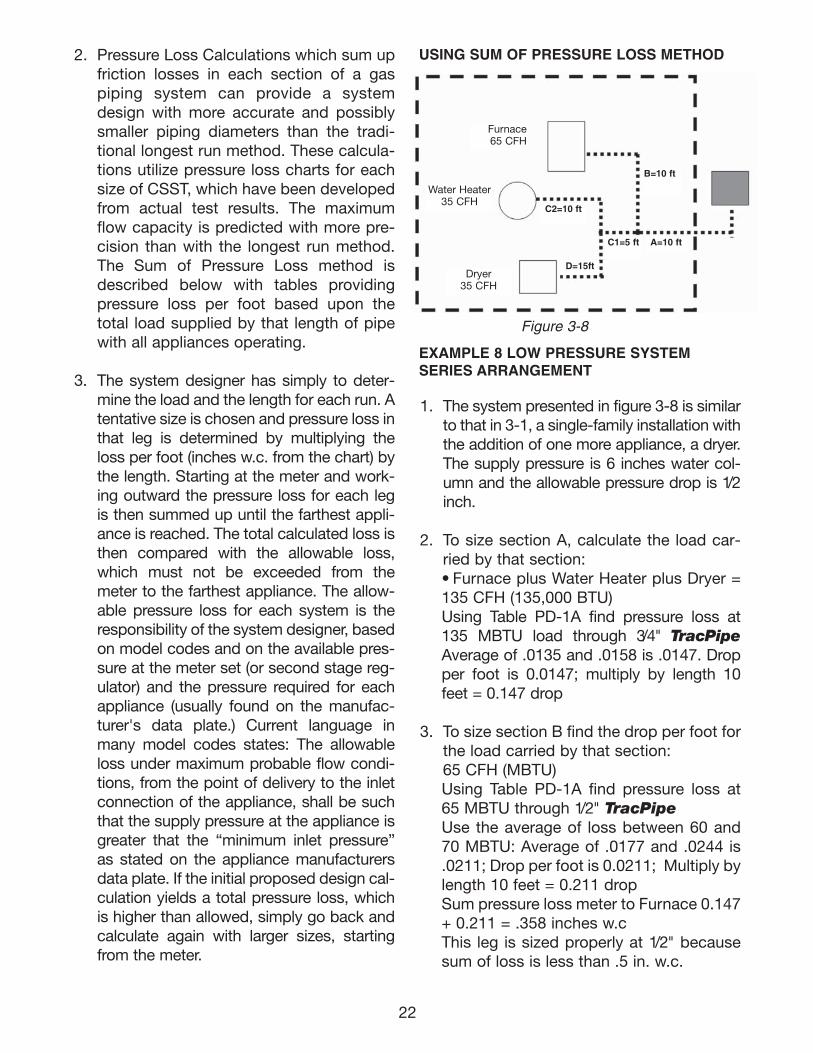
EXAMPLE 8 LOW PRESSURE SYSTEMSERIES ARRANGEMENT
1. The system presented in figure 3-8 is similarto that in 3-1, a single-family installation withthe addition of one more appliance, a dryer.The supply pressure is 6 inches water col-umn and the allowable pressure drop is 1/2inch.
2. To size section A, calculate the load car-ried by that section:• Furnace plus Water Heater plus Dryer =135 CFH (135,000 BTU)Using Table PD-1A find pressure loss at135 MBTU load through 3/4" TracPipeAverage of .0135 and .0158 is .0147. Dropper foot is 0.0147; multiply by length 10feet = 0.147 drop
3. To size section B find the drop per foot forthe load carried by that section: 65 CFH (MBTU)Using Table PD-1A find pressure loss at65 MBTU through 1/2" TracPipeUse the average of loss between 60 and70 MBTU: Average of .0177 and .0244 is.0211; Drop per foot is 0.0211; Multiply bylength 10 feet = 0.211 dropSum pressure loss meter to Furnace 0.147+ 0.211 = .358 inches w.c This leg is sized properly at 1/2" becausesum of loss is less than .5 in. w.c.
22
Furnace65 CFH
B=10 ft
Water Heater35 CFH
Dryer35 CFH
C2=10 ft
D=15ft
C1=5 ft A=10 ft
Figure 3-8
111743_OmegaFlex_Txt:111743_OmegaFlex_Txt 6/5/09 2:17 PM Page 22
4. To size section C1 find the drop per footfor the load carried by that section: 70 CFH (MBTU) Using Table PD-1A find pressureloss at 70 MBTU load through 1/2"TracPipeDrop per foot is .0244; length is 5ft; 5 X .0244 is .122
5. To size section C2 find the dropper foot for the load carried bythat section: 35 CFH (MBTU) Using Table PD-1A find pressureloss at 35 CFH load through 1/2"TracPipeAverage of .0077 and .0042 is.0060; length is 10 ft; 10X .006 is .06Sum pressure loss to water heater0.147 + .122 + .06 = .329 inchesw.cThis leg is sized properly at 1/2" becausesum of loss is less than .5 in. w.c.
6. To size section D find the drop per foot forthe load carried by that section:35 CFH (MBTU)Using Table PD-1A find pressure loss at35 MBTU through 1/2" TracPipeDrop per foot is .006 (see number 4above); Multiply by length 15 feet = .09Sum pressure loss to dryer 0.147 + 0.122+ .09 = .359 inches w.c. This leg is sized properly at 1/2" becausesum of loss is less than .5 in. w.c.
The sum of pressure loss method allows theaddition of an appliance without increasingtrunk line size.
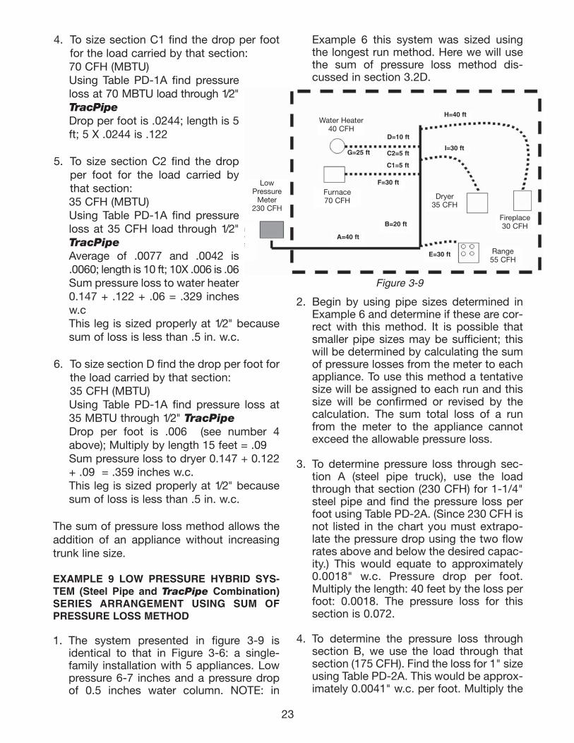
EXAMPLE 9 LOW PRESSURE HYBRID SYS-TEM (Steel Pipe and TracPipe Combination)SERIES ARRANGEMENT USING SUM OFPRESSURE LOSS METHOD
1. The system presented in figure 3-9 isidentical to that in Figure 3-6: a single-family installation with 5 appliances. Lowpressure 6-7 inches and a pressure dropof 0.5 inches water column. NOTE: in
Example 6 this system was sized usingthe longest run method. Here we will usethe sum of pressure loss method dis-cussed in section 3.2D.
2. Begin by using pipe sizes determined inExample 6 and determine if these are cor-rect with this method. It is possible thatsmaller pipe sizes may be sufficient; thiswill be determined by calculating the sumof pressure losses from the meter to eachappliance. To use this method a tentativesize will be assigned to each run and thissize will be confirmed or revised by thecalculation. The sum total loss of a runfrom the meter to the appliance cannotexceed the allowable pressure loss.
3. To determine pressure loss through sec-tion A (steel pipe truck), use the loadthrough that section (230 CFH) for 1-1/4"steel pipe and find the pressure loss perfoot using Table PD-2A. (Since 230 CFH isnot listed in the chart you must extrapo-late the pressure drop using the two flowrates above and below the desired capac-ity.) This would equate to approximately0.0018" w.c. Pressure drop per foot.Multiply the length: 40 feet by the loss perfoot: 0.0018. The pressure loss for thissection is 0.072.
4. To determine the pressure loss throughsection B, we use the load through thatsection (175 CFH). Find the loss for 1" sizeusing Table PD-2A. This would be approx-imately 0.0041" w.c. per foot. Multiply the
23
Water Heater40 CFH
D=10 ft
C2=5 ft
C1=5 ft
Furnace70 CFH
LowPressure
Meter230 CFH
B=20 ft
A=40 ft
E=30 ft
H=40 ft
Dryer35 CFH
Fireplace30 CFH
Range55 CFH
Figure 3-9
I=30 ft
F=30 ft
G=25 ft
LowPressure
Meter230 CFH
111743_OmegaFlex_Txt:111743_OmegaFlex_Txt 6/5/09 2:17 PM Page 23
24
length: 20 feet by the loss per foot:0.0041. The pressure loss for this sectionis 0.0820.
5. To determine the pressure loss throughsection C1 we use the load through thatsection (105 CFH). Find the pressure lossfor 1" using Table PD-2A. This would beapproximately 0.0016" w.c. Multiply thelength: 5 feet by the loss per foot 0.0016.The pressure loss for this section is0.0080" w.c.
6. To determine pressure loss through sec-tion C2 we use the load through that sec-tion (70 CFH). Find the pressure loss for3/4" using Table PD-2A. This would be0.0024' w.c. Multiply the length: 5 feet bythe loss per foot: 0.0024. The pressureloss for this section is 0.0120' w.c.
7. To determine pressure loss through sec-tion D we use the load through that sec-tion (30 CFH). Find the pressure loss for1/2" using Table PD-2A. This would be0.0020” w.c. Multiply the length: 10 feet bythe loss per foot: 0.0020. The pressureloss for this section is 0.0200" w.c.
8. To determine pressure loss through sec-tion E (TracPipe drop to range) use theload through that section (55 CFH) andextrapolate the pressure loss using TablePD-1A. Trying the 3/4" column we find thatthe pressure loss would be approx0.0029" w.c. Multiply the length: 30 feet bythe loss per foot 0.0029. The pressure lossfor this section is 0.0870. Add the loss ofsection A to the loss of section E for thetotal loss from the meter to the range.0.072 + 0.0870 = 0.159. Since this is lessthan the 0.5”w.c. allowable drop the cor-rect size for section E is 3/4".
9. To determine pressure loss through sec-tion F (TracPipe drop to the furnace),use the load (70 CFH) and find pressureloss from Table PD-1A. In the 3/4" columnwe find 0.0038. Multiply the length: 30 feetby 0.0038. The pressure loss for this sec-tion is 0.1140.
Add the loss of sections A + B to the lossof section F for total loss from meter tofurnace. 0.072 + 0.082 + 0.114 = 0.2680.The correct size for section F is 3/4".
10. To determine pressure loss through sec-tion G (TracPipe drop to the waterheater), use the load (40 CFH) and findpressure loss from Table PD-1. In the 1/2"column we find 0.0077. Multiply thelength: 25 feet by 0.008. The pressure lossfor this section is 0.1925. Add the loss ofsections A + B + C1 + C2 to the loss ofsection G for total loss from meter to fur-nace. 0.072 + 0.0820 + 0.0080 + 0.0120 =0.1740. The correct size for section G is1/2".
11. To determine pressure loss through sec-tion H (TracPipe drop to the fireplace),use the load (30 CFH) and find pressureloss from Table PD-1. In the 1/2" columnwe find 0.0042. Multiply the length: 40 feetby 0.0042. The pressure loss for this sec-tion is 0.1680. Add the loss of sections A +B + C1 + C2 + D to the loss of section H fortotal loss from meter to furnace. 0.072 +0.0820 + 0.0080 + 0.0120 + 0.1680 =0.3420. The correct size for section H is1/2".
12. To determine pressure loss through sec-tion I (TracPipe drop to the dryer), use theload (35 CFH) and find pressure loss fromTable PD-1. In the 1/2" column we find0.006. Multiply the length: 30 feet by0.006. The pressure loss for this section is0.18. Add the loss of sections A + B + C1to the loss of section I for total loss frommeter to dryer. 0.072 + 0.0820 + 0.0080 +0.18 = 0.3420. The correct size for sectionI is 1/2". Using the Sum of Pressure LossMethod we calculate that three of the fiveTracPipe sections (when compared withthe longest length method) can utilizereduced sizes to deliver the necessaryload with a pressure loss equal to or lessthan the allowable 0.5 inches water col-umn. This enables the installer to use 1/2"TracPipe on all but the furnace and rangedrops, which remain 3/4".
111743_OmegaFlex_Txt:111743_OmegaFlex_Txt 5/28/09 11:57 AM Page 24
25
CHAPTER 4INSTALLATION PRACTICES
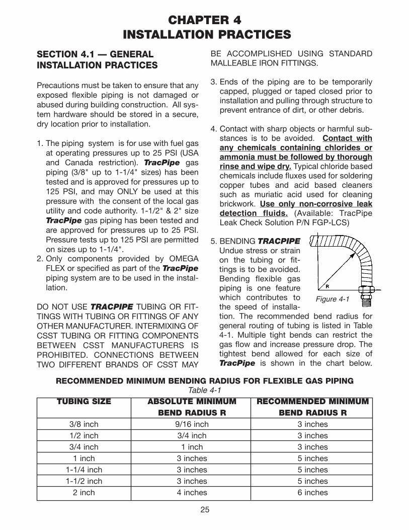
RECOMMENDED MINIMUM BENDING RADIUS FOR FLEXIBLE GAS PIPINGTable 4-1
TUBING SIZE ABSOLUTE MINIMUM RECOMMENDED MINIMUMBEND RADIUS R BEND RADIUS R
3/8 inch 9/16 inch 3 inches1/2 inch 3/4 inch 3 inches3/4 inch 1 inch 3 inches1 inch 3 inches 5 inches
1-1/4 inch 3 inches 5 inches1-1/2 inch 3 inches 5 inches
2 inch 4 inches 6 inches
SECTION 4.1 — GENERAL INSTALLATION PRACTICES
Precautions must be taken to ensure that anyexposed flexible piping is not damaged orabused during building construction. All sys-tem hardware should be stored in a secure,dry location prior to installation.
1. The piping system is for use with fuel gasat operating pressures up to 25 PSI (USAand Canada restriction). TracPipe gaspiping (3/8" up to 1-1/4" sizes) has beentested and is approved for pressures up to125 PSI, and may ONLY be used at thispressure with the consent of the local gasutility and code authority. 1-1/2" & 2" sizeTracPipe gas piping has been tested andare approved for pressures up to 25 PSI.Pressure tests up to 125 PSI are permittedon sizes up to 1-1/4".
2. Only components provided by OMEGAFLEX or specified as part of the TracPipepiping system are to be used in the instal-lation.
DO NOT USE TRACPIPE TUBING OR FIT-TINGS WITH TUBING OR FITTINGS OF ANYOTHER MANUFACTURER. INTERMIXING OFCSST TUBING OR FITTING COMPONENTSBETWEEN CSST MANUFACTURERS ISPROHIBITED. CONNECTIONS BETWEENTWO DIFFERENT BRANDS OF CSST MAY
BE ACCOMPLISHED USING STANDARDMALLEABLE IRON FITTINGS.
3. Ends of the piping are to be temporarilycapped, plugged or taped closed prior toinstallation and pulling through structure toprevent entrance of dirt, or other debris.
4. Contact with sharp objects or harmful sub-stances is to be avoided. Contact withany chemicals containing chlorides orammonia must be followed by thoroughrinse and wipe dry. Typical chloride basedchemicals include fluxes used for solderingcopper tubes and acid based cleanerssuch as muriatic acid used for cleaningbrickwork. Use only non-corrosive leakdetection fluids. (Available: TracPipeLeak Check Solution P/N FGP-LCS)
5. BENDING TRACPIPEUndue stress or strainon the tubing or fit-tings is to be avoided.Bending flexible gaspiping is one featurewhich contributes tothe speed of installa-tion. The recommended bend radius forgeneral routing of tubing is listed in Table4-1. Multiple tight bends can restrict thegas flow and increase pressure drop. Thetightest bend allowed for each size ofTracPipe is shown in the chart below.
Figure 4-1
111743_OmegaFlex_Txt:111743_OmegaFlex_Txt 5/28/09 11:57 AM Page 25
26
Typical locations requiring tight bends aretermination mount installations in hollowstud walls.
6. SUPPORTING TRACPIPEPiping shall be supported in a workman-like manner with pipe straps, bands,brackets or hangers suitable for the sizeand weight of the piping. TracPipewhich passes over or through a structuralmember is considered to be supportedby that member.
6A. VERTICAL RUNSSpacing of supports is not to exceed 10feet, requiring hangers only where theheight of each floor is greater than 10 feet.
6B. HORIZONTAL RUNS Spacing of supports Hangers, supportsand anchors-Piping shall be supportedat intervals not to exceed those shown inTable 4-2. It is acceptable to use standardpipe straps or tubing clips available inmetal or plastic materials, OMEGAFLEXhas found that the use of two-attachmentpoint plastic clips or metal EMT pipestraps is advisable. Some plastic clips, especially the “J-clips” designed to support plastic tubingare susceptible to breakage upon subse-quent handling by other trades.
HORIZONTAL OR INCLINED RUNSTable 4-2
PIPING SIZE SPACING OF SUPPORTS3/8 inch 4 FEET1/2 inch 6 FEET3/4 inch 8 FT. (USA) 6 FT. (CANADA)1 inch 8 FT. (USA) 6 FT. (CANADA)
1-1/4 inch 8 FT. (USA) 6 FT. (CANADA)1-1/2 inch 8 FT. (USA) 6 FT. (CANADA)
2 inch 8 FT. (USA) 6 FT. (CANADA)
111743_OmegaFlex_Txt:111743_OmegaFlex_Txt 5/28/09 11:57 AM Page 26
27
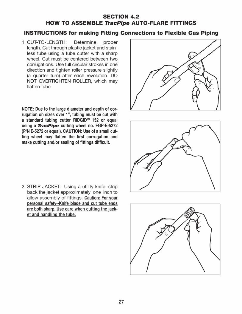
1. CUT-TO-LENGTH: Determine properlength. Cut through plastic jacket and stain-less tube using a tube cutter with a sharpwheel. Cut must be centered between twocorrugations. Use full circular strokes in onedirection and tighten roller pressure slightly(a quarter turn) after each revolution. DONOT OVERTIGHTEN ROLLER, which mayflatten tube.
NOTE: Due to the large diameter and depth of cor-rugation on sizes over 1", tubing must be cut witha standard tubing cutter RIDGIDTM 152 or equalusing a TracPipe cutting wheel no. FGP-E-5272(P/N E-5272 or equal). CAUTION: Use of a small cut-ting wheel may flatten the first corrugation andmake cutting and/or sealing of fittings difficult.
2. STRIP JACKET: Using a utility knife, stripback the jacket approximately one inch toallow assembly of fittings. Caution: For yourpersonal safety--Knife blade and cut tube endsare both sharp. Use care when cutting the jack-et and handling the tube.
SECTION 4.2HOW TO ASSEMBLE TracPipe AUTO-FLARE FITTINGS
INSTRUCTIONS for making Fitting Connections to Flexible Gas Piping
111743_OmegaFlex_Txt:111743_OmegaFlex_Txt 5/28/09 11:57 AM Page 27
28
4. WRENCH FITTING: Place the adapter intothe nut and engage threads. Note that theAutoFlare® fitting is designed to form aleak tight seat on the stainless tubingas you tighten the fitting. (The piloting fea-ture of the adapter will not always enterthe bore of the tubing before the tight-ening operation, but will center the fit-ting when tightened). Using appropriatewrenches, tighten the fitting until adapterbottoms and the resistance to wrenchingincreases greatly. The flare has now beencreated on the tubing end.
CAUTION- DO NOT USE ANY THREADSEALANTS FOR THIS CONNECTION.SEALANTS ARE TO BE USED ON THE PIPETHREAD ONLY.
3. INSTALL FITTING NUT: Slide nut over cutend: place two split-rings into the firstcorrugation next to the tube cut. Slidenut forward to trap the rings.
5. FINAL TORQUE: Tighten nut and adapterto the torque values shown in Table 4-3.For field installations use the followingmethod: Tighten nut and adapter asthough you were making up a flared tubingjoint. Note relation between hex flats atthis point and continue to tighten for twoadditional hex flats (one-third turn) toobtain required torque and final leak-tightseal.
INSTRUCTIONS for making Fitting Connections to Flexible Gas Piping(Continued)
Flexible Pipe Size Fitting Torque Value
3/8" FGP-SS4-375 FGP-FST-375 40 ft.-lb.
1/2" FGP-SS4-500 FGP-FST-500 42 ft.-lb.
3/4" FGP-SS4-750 FGP-FST-750 45 ft.-lb.
1" FGP-SS4-1000 FGP-FST-1000 75 ft.-lb.
1-1/4" FGP-SS4-1250 FGP-FST-1250 150-200 ft.-lb.
1-1/2" FGP-SS4-1500 FGP-FST-1500 200-250 ft.-lb.
2" FGP-SS4-2000 FGP-FST-2000 250-300 ft.-lb.
Table 4-3
111743_OmegaFlex_Txt:111743_OmegaFlex_Txt 5/28/09 11:57 AM Page 28
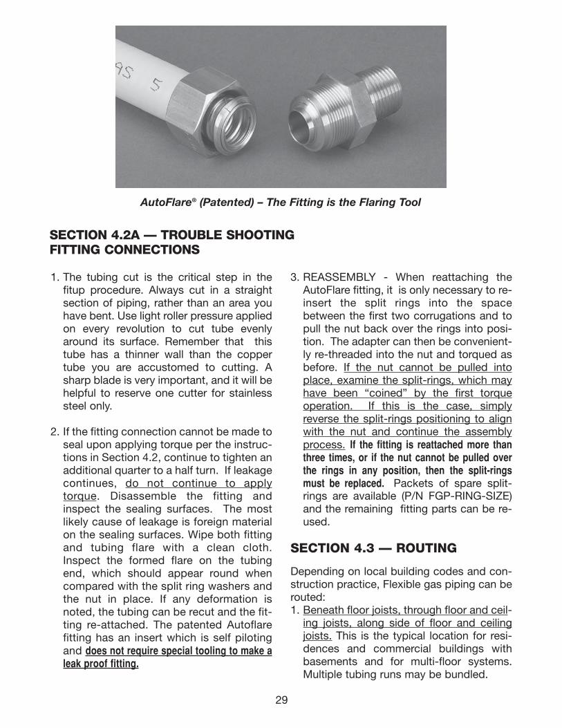
29
SECTION 4.2A — TROUBLE SHOOTINGFITTING CONNECTIONS
AutoFlare® (Patented) – The Fitting is the Flaring Tool
1. The tubing cut is the critical step in thefitup procedure. Always cut in a straightsection of piping, rather than an area youhave bent. Use light roller pressure appliedon every revolution to cut tube evenlyaround its surface. Remember that thistube has a thinner wall than the coppertube you are accustomed to cutting. Asharp blade is very important, and it will behelpful to reserve one cutter for stainlesssteel only.
2. If the fitting connection cannot be made toseal upon applying torque per the instruc-tions in Section 4.2, continue to tighten anadditional quarter to a half turn. If leakagecontinues, do not continue to applytorque. Disassemble the fitting andinspect the sealing surfaces. The mostlikely cause of leakage is foreign materialon the sealing surfaces. Wipe both fittingand tubing flare with a clean cloth.Inspect the formed flare on the tubingend, which should appear round whencompared with the split ring washers andthe nut in place. If any deformation isnoted, the tubing can be recut and the fit-ting re-attached. The patented Autoflarefitting has an insert which is self pilotingand does not require special tooling to make aleak proof fitting.
3. REASSEMBLY - When reattaching theAutoFlare fitting, it is only necessary to re-insert the split rings into the spacebetween the first two corrugations and topull the nut back over the rings into posi-tion. The adapter can then be convenient-ly re-threaded into the nut and torqued asbefore. If the nut cannot be pulled intoplace, examine the split-rings, which mayhave been “coined” by the first torqueoperation. If this is the case, simplyreverse the split-rings positioning to alignwith the nut and continue the assemblyprocess. If the fitting is reattached more thanthree times, or if the nut cannot be pulled overthe rings in any position, then the split-ringsmust be replaced. Packets of spare split-rings are available (P/N FGP-RING-SIZE)and the remaining fitting parts can be re-used.
SECTION 4.3 — ROUTING
Depending on local building codes and con-struction practice, Flexible gas piping can berouted:1. Beneath floor joists, through floor and ceil-
ing joists, along side of floor and ceilingjoists. This is the typical location for resi-dences and commercial buildings withbasements and for multi-floor systems.Multiple tubing runs may be bundled.
111743_OmegaFlex_Txt:111743_OmegaFlex_Txt 5/28/09 11:57 AM Page 29
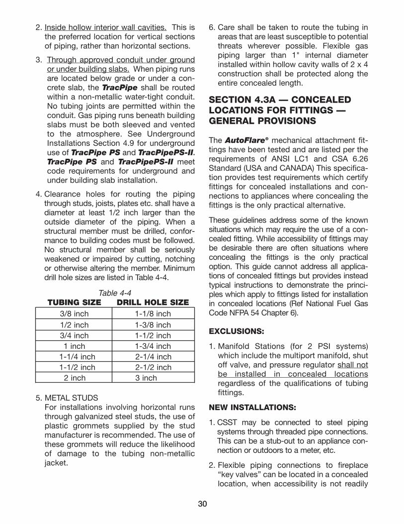
30
2. Inside hollow interior wall cavities. This isthe preferred location for vertical sectionsof piping, rather than horizontal sections.
3. Through approved conduit under groundor under building slabs. When piping runsare located below grade or under a con-crete slab, the TracPipe shall be routedwithin a non-metallic water-tight conduit.No tubing joints are permitted within theconduit. Gas piping runs beneath buildingslabs must be both sleeved and ventedto the atmosphere. See UndergroundInstallations Section 4.9 for undergrounduse of TracPipe PS and TracPipePS-II.TracPipe PS and TracPipePS-II meetcode requirements for underground andunder building slab installation.
4. Clearance holes for routing the pipingthrough studs, joists, plates etc. shall have adiameter at least 1/2 inch larger than theoutside diameter of the piping. When astructural member must be drilled, confor-mance to building codes must be followed.No structural member shall be seriouslyweakened or impaired by cutting, notchingor otherwise altering the member. Minimumdrill hole sizes are listed in Table 4-4.
5. METAL STUDSFor installations involving horizontal runsthrough galvanized steel studs, the use ofplastic grommets supplied by the studmanufacturer is recommended. The use ofthese grommets will reduce the likelihoodof damage to the tubing non-metallicjacket.
6. Care shall be taken to route the tubing inareas that are least susceptible to potentialthreats wherever possible. Flexible gaspiping larger than 1" internal diameterinstalled within hollow cavity walls of 2 x 4construction shall be protected along theentire concealed length.
Table 4-4TUBING SIZE DRILL HOLE SIZE
3/8 inch 1-1/8 inch1/2 inch 1-3/8 inch3/4 inch 1-1/2 inch1 inch 1-3/4 inch
1-1/4 inch 2-1/4 inch1-1/2 inch 2-1/2 inch
2 inch 3 inch
30
SECTION 4.3A — CONCEALED LOCATIONS FOR FITTINGS — GENERAL PROVISIONS
The AutoFlare® mechanical attachment fit-tings have been tested and are listed per therequirements of ANSI LC1 and CSA 6.26Standard (USA and CANADA) This specifica-tion provides test requirements which certifyfittings for concealed installations and con-nections to appliances where concealing thefittings is the only practical alternative.
These guidelines address some of the knownsituations which may require the use of a con-cealed fitting. While accessibility of fittings maybe desirable there are often situations whereconcealing the fittings is the only practicaloption. This guide cannot address all applica-tions of concealed fittings but provides insteadtypical instructions to demonstrate the princi-ples which apply to fittings listed for installationin concealed locations (Ref National Fuel GasCode NFPA 54 Chapter 6).
EXCLUSIONS:
1. Manifold Stations (for 2 PSI systems)which include the multiport manifold, shutoff valve, and pressure regulator shall notbe installed in concealed locationsregardless of the qualifications of tubingfittings.
NEW INSTALLATIONS:
1. CSST may be connected to steel pipingsystems through threaded pipe connections.This can be a stub-out to an appliance con-nection or outdoors to a meter, etc.
2. Flexible piping connections to fireplace“key valves” can be located in a concealedlocation, when accessibility is not readily
111743_OmegaFlex_Txt:111743_OmegaFlex_Txt 5/28/09 11:57 AM Page 30
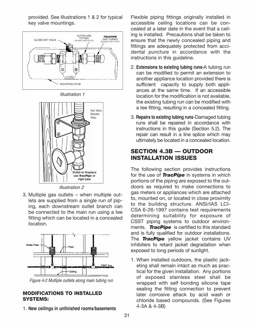
Flexible piping fittings originally installed inaccessible ceiling locations can be con-cealed at a later date in the event that a ceil-ing is installed. Precautions shall be taken toensure that the newly concealed piping andfittings are adequately protected from acci-dental puncture in accordance with theinstructions in this guideline.
2. Extensions to existing tubing runs-A tubing runcan be modified to permit an extension toanother appliance location provided there issufficient capacity to supply both appli-ances at the same time. If an accessiblelocation for the modification is not available,the existing tubing run can be modified witha tee fitting, resulting in a concealed fitting.
3. Repairs to existing tubing runs-Damaged tubingruns shall be repaired in accordance withinstructions in this guide (Section 5.2). Therepair can result in a line splice which mayultimately be located in a concealed location.
SECTION 4.3B — OUTDOORINSTALLATION ISSUES
The following section provides instructionsfor the use of TracPipe in systems in whichportions of the piping are exposed to the out-doors as required to make connections togas meters or appliances which are attachedto, mounted on, or located in close proximityto the building structure. ANSI/IAS LCI-CSA 6-26-1997 contains test requirementsdetermining suitability for exposure ofCSST piping systems to outdoor environ-ments. TracPipe is certified to this standardand is fully qualified for outdoor installations.The TracPipe yellow jacket contains UVinhibiters to retard jacket degradation whenexposed to long periods of sunlight.
1. When installed outdoors, the plastic jack-eting shall remain intact as much as prac-tical for the given installation. Any portionsof exposed stainless steel shall bewrapped with self bonding silicone tapesealing the fitting connection to preventlater corrosive attack by acid wash orchloride based compounds. (See Figures4-3A & 4-3B)
provided. See Illustrations 1 & 2 for typicalkey valve mountings.
3. Multiple gas outlets – when multiple out-lets are supplied from a single run of pip-ing, each downstream outlet branch canbe connected to the main run using a teefitting which can be located in a concealedlocation.
MODIFICATIONS TO INSTALLEDSYSTEMS:
1. New ceilings in unfinished rooms/basements
Figure 4-2 Multiple outlets along main tubing run
31
Illustration 1
GLOBE KEY VALVE
MOUNTING STUB
AUTOFLAREFITTING
(ON INLET AND OUTLET)
TRACPIPEGAS TUBING
(ON INLET AND OUTLET)
C-CLAMPSFOR SUPPORT
Outlet to fireplaceuse TracPipe or
rigid pipe
Key ValveBracketAssy.
Illustration 2
111743_OmegaFlex_Txt:111743_OmegaFlex_Txt 5/28/09 11:57 AM Page 31
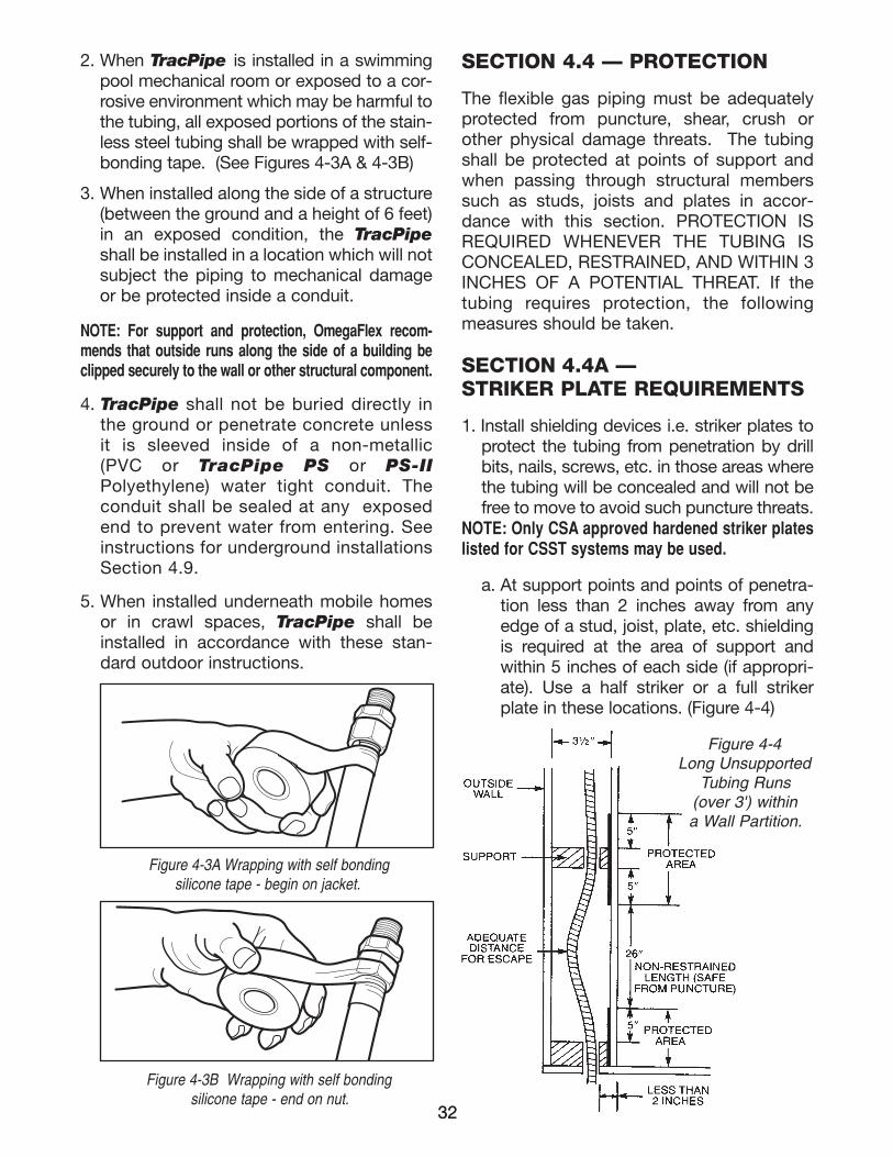
32
2. When TracPipe is installed in a swimmingpool mechanical room or exposed to a cor-rosive environment which may be harmful tothe tubing, all exposed portions of the stain-less steel tubing shall be wrapped with self-bonding tape. (See Figures 4-3A & 4-3B)
3. When installed along the side of a structure(between the ground and a height of 6 feet)in an exposed condition, the TracPipeshall be installed in a location which will notsubject the piping to mechanical damageor be protected inside a conduit.
NOTE: For support and protection, OmegaFlex recom-mends that outside runs along the side of a building beclipped securely to the wall or other structural component.
4. TracPipe shall not be buried directly inthe ground or penetrate concrete unlessit is sleeved inside of a non-metal lic(PVC or TracPipe PS or PS-IIPolyethylene) water tight conduit. Theconduit shall be sealed at any exposedend to prevent water from entering. Seeinstructions for underground installationsSection 4.9.
5. When installed underneath mobile homesor in crawl spaces, TracPipe shall beinstalled in accordance with these stan-dard outdoor instructions.
SECTION 4.4 — PROTECTION
The flexible gas piping must be adequatelyprotected from puncture, shear, crush orother physical damage threats. The tubingshall be protected at points of support andwhen passing through structural memberssuch as studs, joists and plates in accor-dance with this section. PROTECTION ISREQUIRED WHENEVER THE TUBING ISCONCEALED, RESTRAINED, AND WITHIN 3INCHES OF A POTENTIAL THREAT. If thetubing requires protection, the followingmeasures should be taken.
SECTION 4.4A —STRIKER PLATE REQUIREMENTS
1. Install shielding devices i.e. striker plates toprotect the tubing from penetration by drillbits, nails, screws, etc. in those areas wherethe tubing will be concealed and will not befree to move to avoid such puncture threats.
NOTE: Only CSA approved hardened striker plateslisted for CSST systems may be used.
a. At support points and points of penetra-tion less than 2 inches away from anyedge of a stud, joist, plate, etc. shieldingis required at the area of support andwithin 5 inches of each side (if appropri-ate). Use a half striker or a full strikerplate in these locations. (Figure 4-4)
32
Figure 4-3A Wrapping with self bonding silicone tape - begin on jacket.
Figure 4-3B Wrapping with self bondingsilicone tape - end on nut.
Figure 4-4Long Unsupported
Tubing Runs(over 3') within a Wall Partition.
111743_OmegaFlex_Txt:111743_OmegaFlex_Txt 5/28/09 11:57 AM Page 32
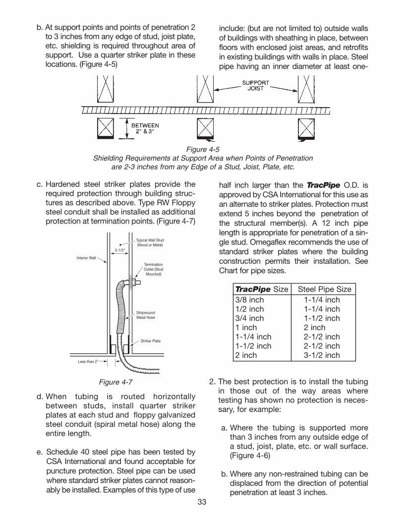
half inch larger than the TracPipe O.D. isapproved by CSA International for this use asan alternate to striker plates. Protection mustextend 5 inches beyond the penetration ofthe structural member(s). A 12 inch pipelength is appropriate for penetration of a sin-gle stud. Omegaflex recommends the use ofstandard striker plates where the buildingconstruction permits their installation. SeeChart for pipe sizes.
2. The best protection is to install the tubing i n those out of the way areas wheretesting has shown no protection is neces-sary, for example:
a. Where the tubing is supported morethan 3 inches from any outside edge ofa stud, joist, plate, etc. or wall surface.(Figure 4-6)
b. Where any non-restrained tubing can bedisplaced from the direction of potentialpenetration at least 3 inches.
include: (but are not limited to) outside wallsof buildings with sheathing in place, betweenfloors with enclosed joist areas, and retrofitsin existing buildings with walls in place. Steelpipe having an inner diameter at least one-
33
b. At support points and points of penetration 2to 3 inches from any edge of stud, joist plate,etc. shielding is required throughout area ofsupport. Use a quarter striker plate in theselocations. (Figure 4-5)
c. Hardened steel striker plates provide therequired protection through building struc-tures as described above. Type RW Floppysteel conduit shall be installed as additionalprotection at termination points. (Figure 4-7)
d. When tubing is routed horizontallybetween studs, install quarter strikerplates at each stud and floppy galvanizedsteel conduit (spiral metal hose) along theentire length.
e. Schedule 40 steel pipe has been tested byCSA International and found acceptable forpuncture protection. Steel pipe can be usedwhere standard striker plates cannot reason-ably be installed. Examples of this type of use
Figure 4-5Shielding Requirements at Support Area when Points of Penetration
are 2-3 inches from any Edge of a Stud, Joist, Plate, etc.
Typical Wall Stud(Wood or Metal)
TerminationOutlet (StudMounted)
StripwoundMetal Hose
Striker Plate
Interior Wall
3-1/2"
Less than 2"
Figure 4-7
TracPipe Size Steel Pipe Size3/8 inch 1-1/4 inch1/2 inch 1-1/4 inch3/4 inch 1-1/2 inch1 inch 2 inch1-1/4 inch 2-1/2 inch1-1/2 inch 2-1/2 inch2 inch 3-1/2 inch
111743_OmegaFlex_Txt:111743_OmegaFlex_Txt 5/28/09 11:57 AM Page 33
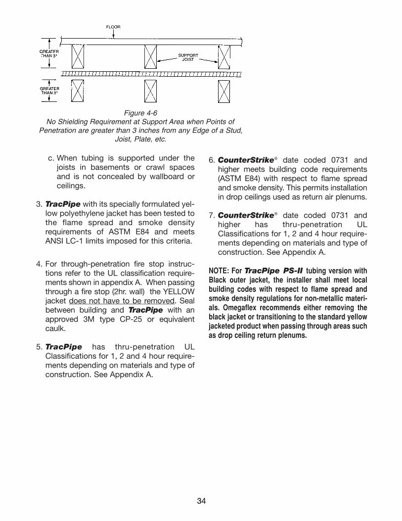
3434
Figure 4-6No Shielding Requirement at Support Area when Points of
Penetration are greater than 3 inches from any Edge of a Stud, Joist, Plate, etc.
c. When tubing is supported under thejoists in basements or crawl spacesand is not concealed by wallboard orceilings.
3. TracPipe with its specially formulated yel-low polyethylene jacket has been tested tothe flame spread and smoke densityrequirements of ASTM E84 and meetsANSI LC-1 limits imposed for this criteria.
4. For through-penetration fire stop instruc-tions refer to the UL classification require-ments shown in appendix A. When passingthrough a fire stop (2hr. wall) the YELLOWjacket does not have to be removed. Sealbetween building and TracPipe with anapproved 3M type CP-25 or equivalentcaulk.
5. TracPipe has thru-penetration ULClassifications for 1, 2 and 4 hour require-ments depending on materials and type ofconstruction. See Appendix A.
6. CounterStrike® date coded 0731 andhigher meets building code requirements(ASTM E84) with respect to flame spreadand smoke density. This permits installationin drop ceilings used as return air plenums.
7. CounterStrike® date coded 0731 andhigher has thru-penetration ULClassifications for 1, 2 and 4 hour require-ments depending on materials and type ofconstruction. See Appendix A.
NOTE: For TracPipe PS-II tubing version withBlack outer jacket, the installer shall meet localbuilding codes with respect to flame spread andsmoke density regulations for non-metallic materi-als. Omegaflex recommends either removing theblack jacket or transitioning to the standard yellowjacketed product when passing through areas suchas drop ceiling return plenums.
111743_OmegaFlex_Txt:111743_OmegaFlex_Txt 5/28/09 11:57 AM Page 34
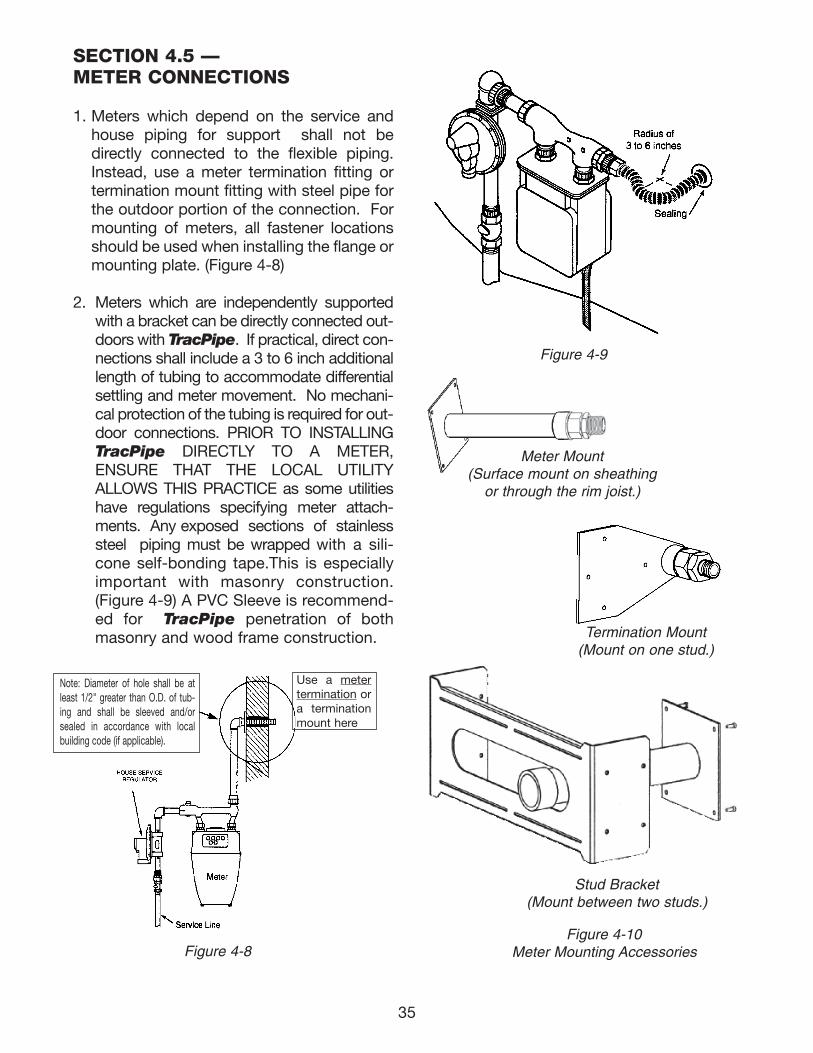
Use a metertermination or a terminationmount here
SECTION 4.5 —METER CONNECTIONS
1. Meters which depend on the service andhouse piping for support shall not bedirectly connected to the flexible piping.Instead, use a meter termination fitting ortermination mount fitting with steel pipe forthe outdoor portion of the connection. Formounting of meters, all fastener locationsshould be used when installing the flange ormounting plate. (Figure 4-8)
2. Meters which are independently supportedwith a bracket can be directly connected out-doors with TracPipe. If practical, direct con-nections shall include a 3 to 6 inch additionallength of tubing to accommodate differentialsettling and meter movement. No mechani-cal protection of the tubing is required for out-door connections. PRIOR TO INSTALLINGTracPipe DIRECTLY TO A METER,ENSURE THAT THE LOCAL UTILITYALLOWS THIS PRACTICE as some utilitieshave regulations specifying meter attach-ments. Any exposed sections of stainlesssteel piping must be wrapped with a sili-cone self-bonding tape.This is especiallyimportant with masonry construction.(Figure 4-9) A PVC Sleeve is recommend-ed for TracPipe penetration of bothmasonry and wood frame construction.
Figure 4-9
Figure 4-8
Meter Mount(Surface mount on sheathing
or through the rim joist.)
Termination Mount(Mount on one stud.)
Figure 4-10Meter Mounting Accessories
35
Note: Diameter of hole shall be atleast 1/2" greater than O.D. of tub-ing and shall be sleeved and/orsealed in accordance with localbuilding code (if applicable).
Stud Bracket(Mount between two studs.)
111743_OmegaFlex_Txt:111743_OmegaFlex_Txt 5/28/09 11:57 AM Page 35
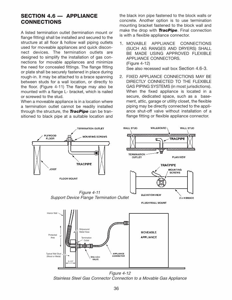
Typical Wall Stud(Wood or Metal)
TerminationOutlet
StripwoundMetal Hose
Interior Wall
ProtectedArea
3-1/2"
6"
36
Figure 4-12Stainless Steel Gas Connector Connection to a Movable Gas Appliance
Figure 4-11Support Device Flange Termination Outlet
SECTION 4.6 — APPLIANCECONNECTIONS
A listed termination outlet (termination mount orflange fitting) shall be installed and secured to thestructure at all floor & hollow wall piping outletsused for moveable appliances and quick discon-nect devices. The termination outlets aredesigned to simplify the installation of gas con-nections for movable appliances and minimizethe need for concealed fittings. The flange fittingor plate shall be securely fastened in place duringrough-in. It may be attached to a brace spanningbetween studs for a wall location, or directly tothe floor. (Figure 4-11) The flange may also bemounted with a flange L- bracket, which is nailedor screwed to the stud.When a moveable appliance is in a location wherea termination outlet cannot be readily installedthrough the structure, the TracPipe can be tran-sitioned to black pipe at a suitable location and
the black iron pipe fastened to the block walls orconcrete. Another option is to use terminationmounting bracket fastened to the block wall andmake the drop with TracPipe. Final connectionis with a flexible appliance connector.
1. MOVABLE APPLIANCE CONNECTIONS(SUCH AS RANGES AND DRYERS) SHALLBE MADE USING APPROVED FLEXIBLEAPPLIANCE CONNECTORS.(Figure 4-12) See also recessed wall box Section 4.6-3.
2. FIXED APPLIANCE CONNECTIONS MAY BEDIRECTLY CONNECTED TO THE FLEXIBLEGAS PIPING SYSTEMS (in most jurisdictions).When the fixed appliance is located in asecure, dedicated space, such as a base-ment, attic, garage or utility closet, the flexiblepiping may be directly connected to the appli-ance shut-off valve without installation of aflange fitting or flexible appliance connector.
111743_OmegaFlex_Txt:111743_OmegaFlex_Txt 5/28/09 11:57 AM Page 36
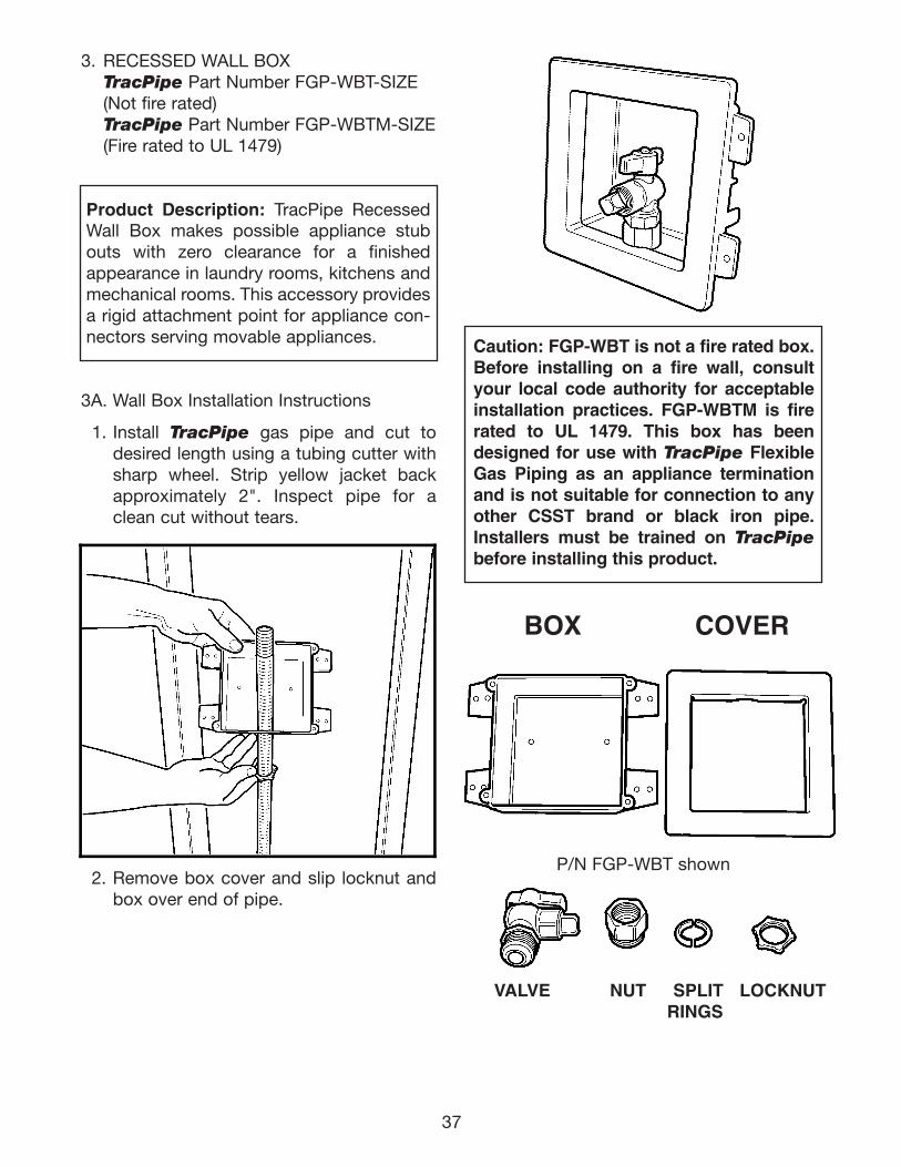
37
3. RECESSED WALL BOXTracPipe Part Number FGP-WBT-SIZE(Not fire rated)TracPipe Part Number FGP-WBTM-SIZE(Fire rated to UL 1479)
Product Description: TracPipe RecessedWall Box makes possible appliance stubouts with zero clearance for a finishedappearance in laundry rooms, kitchens andmechanical rooms. This accessory providesa rigid attachment point for appliance con-nectors serving movable appliances.
3A. Wall Box Installation Instructions
1. Install TracPipe gas pipe and cut todesired length using a tubing cutter withsharp wheel. Strip yellow jacket backapproximately 2". Inspect pipe for aclean cut without tears.
2. Remove box cover and slip locknut andbox over end of pipe.
Caution: FGP-WBT is not a fire rated box.Before installing on a fire wall, consultyour local code authority for acceptableinstallation practices. FGP-WBTM is firerated to UL 1479. This box has beendesigned for use with TracPipe FlexibleGas Piping as an appliance terminationand is not suitable for connection to anyother CSST brand or black iron pipe.Installers must be trained on TracPipebefore installing this product.
VALVE NUT SPLIT LOCKNUTRINGS
BOX COVER
P/N FGP-WBT shown
111743_OmegaFlex_Txt:111743_OmegaFlex_Txt 5/28/09 11:57 AM Page 37
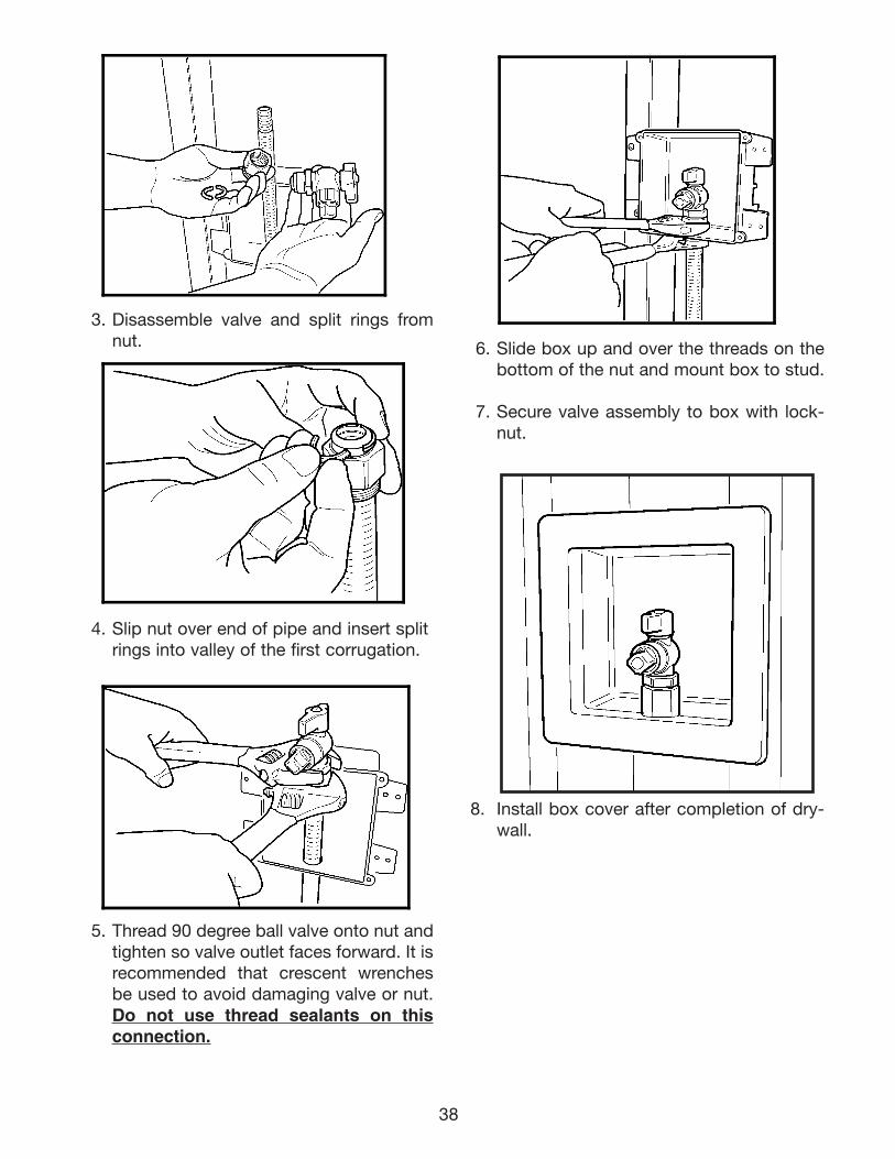
38
6. Slide box up and over the threads on thebottom of the nut and mount box to stud.
7. Secure valve assembly to box with lock-nut.
8. Install box cover after completion of dry-wall.
3. Disassemble valve and split rings fromnut.
4. Slip nut over end of pipe and insert splitrings into valley of the first corrugation.
5. Thread 90 degree ball valve onto nut andtighten so valve outlet faces forward. It isrecommended that crescent wrenchesbe used to avoid damaging valve or nut.Do not use thread sealants on thisconnection.
111743_OmegaFlex_Txt:111743_OmegaFlex_Txt 5/28/09 11:57 AM Page 38
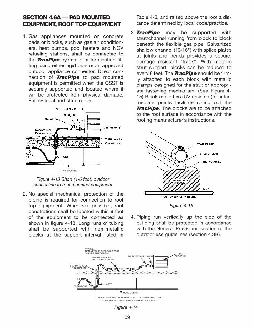
SECTION 4.6A — PAD MOUNTEDEQUIPMENT, ROOF TOP EQUIPMENT
1. Gas appliances mounted on concretepads or blocks, such as gas air condition-ers, heat pumps, pool heaters and NGVrefueling stations, shall be connected tothe TracPipe system at a termination fit-ting using either rigid pipe or an approvedoutdoor appliance connector. Direct con-nection of TracPipe to pad mountedequipment is permitted when the CSST issecurely supported and located where itwill be protected from physical damage.Follow local and state codes.
2. No special mechanical protection of thepiping is required for connection to rooftop equipment. Whenever possible, roofpenetrations shall be located within 6 feetof the equipment to be connected asshown in figure 4-13. Long runs of tubingshall be supported with non-metallicblocks at the support interval listed in
Table 4-2, and raised above the roof a dis-tance determined by local code/practice.
3. TracPipe may be supported withstrut/channel running from block to blockbeneath the flexible gas pipe. Galvanizedshallow channel (13/16") with splice platesat joints and bends provides a secure,damage resistant “track”. With metallicstrut support, blocks can be reduced toevery 8 feet. The TracPipe should be firm-ly attached to each block with metallicclamps designed for the strut or appropri-ate fastening mechanism. (See Figure 4-15) Black cable ties (UV resistant) at inter-mediate points facilitate rolling out theTracPipe. The blocks are to be attachedto the roof surface in accordance with theroofing manufacturer’s instructions.
4. Piping run vertically up the side of thebuilding shall be protected in accordancewith the General Provisions section of theoutdoor use guidelines (section 4.3B).
39
Figure 4-15
Figure 4-13 Short (1-6 foot) outdoorconnection to roof mounted equipment
Figure 4-14
TYPICAL:NON-METALLIC TUBING SUPPORTSPACING PER TABLE 4-2
*TUBING ELEVATED4-6" TYP. ABOVE ROOF
STANDARD ROOFPENETRATION
TUBING CLIPCSST
HUNG CEILING
SHUT-OFF VALVE UNIONGAS
APPLIANCE
*HEIGHT OF ELEVATION BASED ON LOCAL PLUMBING/BUILDINGCODE REQUIREMENTS AND/OR WINTER ICE BUILDUP.
Hung Ceiling
111743_OmegaFlex_Txt:111743_OmegaFlex_Txt 5/28/09 11:57 AM Page 39
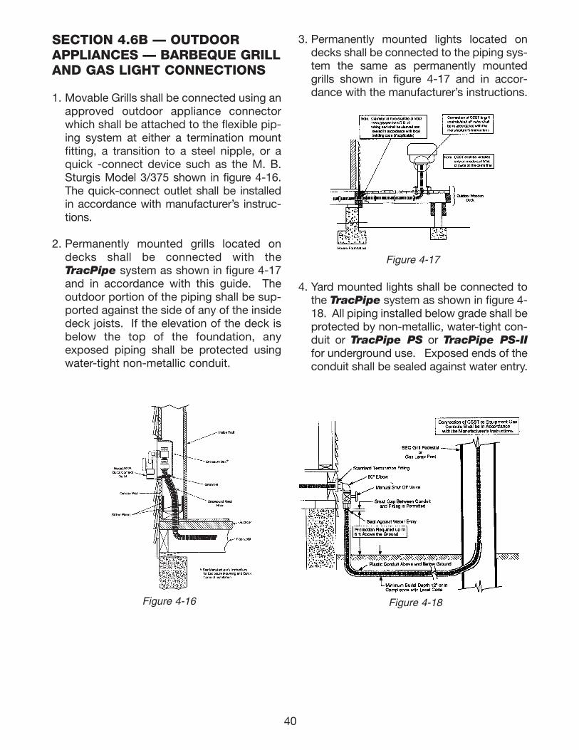
SECTION 4.6B — OUTDOORAPPLIANCES — BARBEQUE GRILLAND GAS LIGHT CONNECTIONS
1. Movable Grills shall be connected using anapproved outdoor appliance connectorwhich shall be attached to the flexible pip-ing system at either a termination mountfitting, a transition to a steel nipple, or aquick -connect device such as the M. B.Sturgis Model 3/375 shown in figure 4-16.The quick-connect outlet shall be installedin accordance with manufacturer’s instruc-tions.
2. Permanently mounted grills located ondecks shall be connected with theTracPipe system as shown in figure 4-17and in accordance with this guide. Theoutdoor portion of the piping shall be sup-ported against the side of any of the insidedeck joists. If the elevation of the deck isbelow the top of the foundation, anyexposed piping shall be protected usingwater-tight non-metallic conduit.
3. Permanently mounted lights located ondecks shall be connected to the piping sys-tem the same as permanently mountedgrills shown in figure 4-17 and in accor-dance with the manufacturer’s instructions.
4. Yard mounted lights shall be connected tothe TracPipe system as shown in figure 4-18. All piping installed below grade shall beprotected by non-metallic, water-tight con-duit or TracPipe PS or TracPipe PS-IIfor underground use. Exposed ends of theconduit shall be sealed against water entry.
40
Figure 4-17
Figure 4-16 Figure 4-18
111743_OmegaFlex_Txt:111743_OmegaFlex_Txt 5/28/09 11:57 AM Page 40
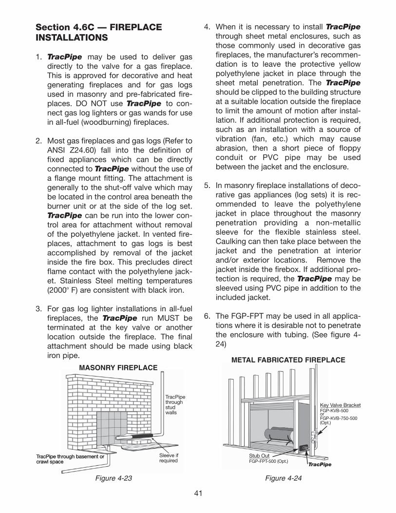
41
Section 4.6C — FIREPLACEINSTALLATIONS
1. TracPipe may be used to deliver gasdirectly to the valve for a gas fireplace.This is approved for decorative and heatgenerating fireplaces and for gas logsused in masonry and pre-fabricated fire-places. DO NOT use TracPipe to con-nect gas log lighters or gas wands for usein all-fuel (woodburning) fireplaces.
2. Most gas fireplaces and gas logs (Refer toANSI Z24.60) fall into the definition offixed appliances which can be directlyconnected to TracPipe without the use ofa flange mount fitting. The attachment isgenerally to the shut-off valve which maybe located in the control area beneath theburner unit or at the side of the log set.TracPipe can be run into the lower con-trol area for attachment without removalof the polyethylene jacket. In vented fire-places, attachment to gas logs is bestaccomplished by removal of the jacketinside the fire box. This precludes directflame contact with the polyethylene jack-et. Stainless Steel melting temperatures(2000o F) are consistent with black iron.
3. For gas log lighter installations in all-fuelfireplaces, the TracPipe run MUST beterminated at the key valve or anotherlocation outside the fireplace. The finalattachment should be made using blackiron pipe.
4. When it is necessary to install TracPipethrough sheet metal enclosures, such asthose commonly used in decorative gasfireplaces, the manufacturer’s recommen-dation is to leave the protective yellowpolyethylene jacket in place through thesheet metal penetration. The TracPipeshould be clipped to the building structureat a suitable location outside the fireplaceto limit the amount of motion after instal-lation. If additional protection is required,such as an installation with a source ofvibration (fan, etc.) which may causeabrasion, then a short piece of floppyconduit or PVC pipe may be usedbetween the jacket and the enclosure.
5. In masonry fireplace installations of deco-rative gas appliances (log sets) it is rec-ommended to leave the polyethylenejacket in place throughout the masonrypenetration providing a non-metallicsleeve for the flexible stainless steel.Caulking can then take place between thejacket and the penetration at interiorand/or exterior locations. Remove thejacket inside the firebox. If additional pro-tection is required, the TracPipe may besleeved using PVC pipe in addition to theincluded jacket.
6. The FGP-FPT may be used in all applica-tions where it is desirable not to penetratethe enclosure with tubing. (See figure 4-24)
Figure 4-23 Figure 4-24
TracPipe through basement orcrawl spaceTracPipe through basement orcrawl space
Sleeve ifrequired
TracPipethroughstudwalls
Key Valve BracketFGP-KVB-500orFGP-KVB-750-500(Opt.)
TracPipe
Stub OutFGP-FPT-500 (Opt.)
MASONRY FIREPLACEMETAL FABRICATED FIREPLACE
111743_OmegaFlex_Txt:111743_OmegaFlex_Txt 5/28/09 11:57 AM Page 41
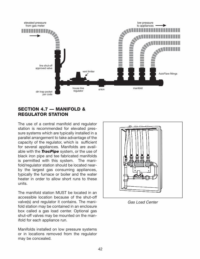
42
elevated pressurefrom gas meter
line shut-offapproved valve
AutoFlare fittings
dirt trap pocketper code
low pressureto appliances
house lineregulator
manifold
vent limiter
union
SECTION 4.7 — MANIFOLD ®ULATOR STATION
The use of a central manifold and regulatorstation is recommended for elevated pres-sure systems which are typically installed in aparallel arrangement to take advantage of thecapacity of the regulator, which is sufficientfor several appliances. Manifolds are avail-able with the TracPipe system, or the use ofblack iron pipe and tee fabricated manifoldsis permitted with this system. The mani-fold/regulator station should be located near-by the largest gas consuming appliances,typically the furnace or boiler and the waterheater in order to allow short runs to theseunits.
The manifold station MUST be located in anaccessible location because of the shut-offvalve(s) and regulator it contains. The mani-fold station may be contained in an enclosurebox called a gas load center. Optional gasshut-off valves may be mounted on the man-ifold for each appliance run.
Manifolds installed on low pressure systemsor in locations removed from the regulatormay be concealed.
Gas Load Center
111743_OmegaFlex_Txt:111743_OmegaFlex_Txt 5/28/09 11:57 AM Page 42
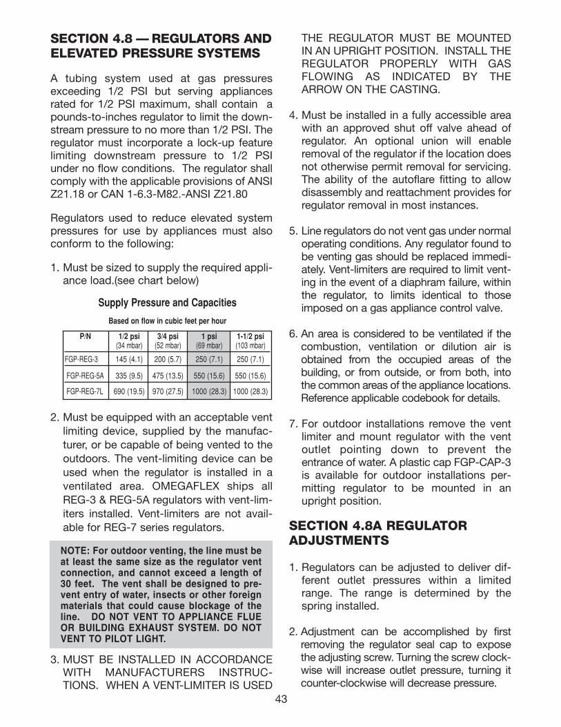
43
SECTION 4.8 — REGULATORS ANDELEVATED PRESSURE SYSTEMS
A tubing system used at gas pressuresexceeding 1/2 PSI but serving appliancesrated for 1/2 PSI maximum, shall contain apounds-to-inches regulator to limit the down-stream pressure to no more than 1/2 PSI. Theregulator must incorporate a lock-up featurelimiting downstream pressure to 1/2 PSIunder no flow conditions. The regulator shallcomply with the applicable provisions of ANSIZ21.18 or CAN 1-6.3-M82.-ANSI Z21.80
Regulators used to reduce elevated systempressures for use by appliances must alsoconform to the following:
1. Must be sized to supply the required appli-ance load.(see chart below)
2. Must be equipped with an acceptable ventlimiting device, supplied by the manufac-turer, or be capable of being vented to theoutdoors. The vent-limiting device can beused when the regulator is installed in aventilated area. OMEGAFLEX ships allREG-3 & REG-5A regulators with vent-lim-iters installed. Vent-limiters are not avail-able for REG-7 series regulators.
3. MUST BE INSTALLED IN ACCORDANCEWITH MANUFACTURERS INSTRUC-TIONS. WHEN A VENT-LIMITER IS USED
THE REGULATOR MUST BE MOUNTEDIN AN UPRIGHT POSITION. INSTALL THEREGULATOR PROPERLY WITH GASFLOWING AS INDICATED BY THEARROW ON THE CASTING.
4. Must be installed in a fully accessible areawith an approved shut off valve ahead ofregulator. An optional union will enableremoval of the regulator if the location doesnot otherwise permit removal for servicing.The ability of the autoflare fitting to allowdisassembly and reattachment provides forregulator removal in most instances.
5. Line regulators do not vent gas under normaloperating conditions. Any regulator found tobe venting gas should be replaced immedi-ately. Vent-limiters are required to limit vent-ing in the event of a diaphram failure, withinthe regulator, to limits identical to thoseimposed on a gas appliance control valve.
6. An area is considered to be ventilated if thecombustion, ventilation or dilution air isobtained from the occupied areas of thebuilding, or from outside, or from both, intothe common areas of the appliance locations.Reference applicable codebook for details.
7. For outdoor installations remove the ventlimiter and mount regulator with the ventoutlet pointing down to prevent theentrance of water. A plastic cap FGP-CAP-3is available for outdoor installations per-mitting regulator to be mounted in anupright position.
SECTION 4.8A REGULATORADJUSTMENTS
1. Regulators can be adjusted to deliver dif-ferent outlet pressures within a limitedrange. The range is determined by thespring installed.
2. Adjustment can be accomplished by firstremoving the regulator seal cap to exposethe adjusting screw. Turning the screw clock-wise will increase outlet pressure, turning itcounter-clockwise will decrease pressure.
NOTE: For outdoor venting, the line must beat least the same size as the regulator ventconnection, and cannot exceed a length of30 feet. The vent shall be designed to pre-vent entry of water, insects or other foreignmaterials that could cause blockage of theline. DO NOT VENT TO APPLIANCE FLUEOR BUILDING EXHAUST SYSTEM. DO NOTVENT TO PILOT LIGHT.
Supply Pressure and Capacities
Based on flow in cubic feet per hour
P/N 1/2 psi 3/4 psi 1 psi 1-1/2 psi (34 mbar) (52 mbar) (69 mbar) (103 mbar)
FGP-REG-3 145 (4.1) 200 (5.7) 250 (7.1) 250 (7.1)
FGP-REG-5A 335 (9.5) 475 (13.5) 550 (15.6) 550 (15.6)
FGP-REG-7L 690 (19.5) 970 (27.5) 1000 (28.3) 1000 (28.3)
111743_OmegaFlex_Txt:111743_OmegaFlex_Txt 5/28/09 11:57 AM Page 43
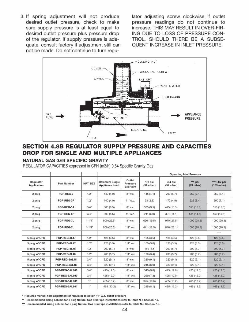
APPLIANCEPRESSURE
SECTION 4.8B REGULATOR SUPPLY PRESSURE AND CAPACITIESDROP FOR SINGLE AND MULTIPLE APPLIANCESNATURAL GAS 0.64 SPECIFIC GRAVITYREGULATOR CAPACITIES expressed in CFH (m3/h) 0.64 Specific Gravity Gas
3. If spring adjustment will not producedesired outlet pressure, check to makesure supply pressure is at least equal todesired outlet pressure plus pressure dropof the regulator. If supply pressure is ade-quate, consult factory if adjustment still cannot be made. Do not continue to turn regu-
lator adjusting screw clockwise if outletpressure readings do not continue toincrease. THIS MAY RESULT IN OVER-FIR-ING DUE TO LOSS OF PRESSURE CON-TROL, SHOULD THERE BE A SUBSE-QUENT INCREASE IN INLET PRESSURE.
Operating Inlet Pressure
Regulator Application Part Number NPT SIZE Maximum Single
Appliance Load
Outlet Pressure Set Point
1/2 psi (34 mbar)
3/4 psi (52 mbar)
**1 psi (69 mbar)
***1-1/2 psi (103 mbar)
2 psig FGP-REG-3 1/2” 140 (4.0) 8” w.c. 145 (4.1) 200 (5.7) 250 (7.1) 250 (7.1)
2 psig FGP-REG-3P 1/2” 140 (4.0) 11” w.c. 93 (2.6) 172 (4.9) 225 (6.4) 250 (7.1)
2 psig FGP-REG-5A 3/4” 300 (8.5) 8” w.c. 335 (9.5) 475 (13.5) 550 (15.6) 550 (15.6)
2 psig FGP-REG-5P 3/4” 300 (8.5) 11” w.c. 211 (6.0) 391 (11.1) 511 (14.5) 550 (15.6)
2 psig FGP-REG-7L 1-1/4” 900 (25.5) 8” w.c. 690 (19.5) 970 (27.5) 1000 (28.3) 1000 (28.3)
2 psig FGP-REG-7L 1-1/4” 900 (25.5) *11” w.c. 441 (12.5) 816 (23.1) 1000 (28.3) 1000 (28.3)
***
5 psig w/ OPD FGP-REG-3L47 1/2” 125 (3.5) 8” w.c. 125 (3.5) 125 (3.5) 125 (3.5) 125 (3.5)
5 psig w/ OPD FGP-REG-3L47 1/2” 125 (3.5) *11” w.c. 105 (3.0) 125 (3.5) 125 (3.5) 125 (3.5)
5 psig w/ OPD FGP-REG-3L48 1/2” 200 (5.7) 8” w.c. 160 (4.5) 200 (5.7) 200 (5.7) 200 (5.7)
5 psig w/ OPD FGP-REG-3L48 1/2” 200 (5.7) *11” w.c. 120 (3.4) 200 (5.7) 200 (5.7) 200 (5.7)
5 psig w/ OPD FGP-REG-5AL48 3/4” 320 (9.1) 8” w.c. 320 (9.1) 320 (9.1) 320 (9.1) 320 (9.1)
5 psig w/ OPD FGP-REG-5AL48 3/4” 320 (9.1) *11” w.c. 245 (6.9) 320 (9.1) 320 (9.1) 320 (9.1)
5 psig w/ OPD FGP-REG-5AL600 3/4” 425 (12.0) 8” w.c. 345 (9.8) 425 (12.0) 425 (12.0) 425 (12.0)
5 psig w/ OPD FGP-REG-5AL600 3/4” 425 (12.0) *11” w.c. 260 (7.3) 425 (12.0) 425 (12.0) 425 (12.0)
5 psig w/ OPD FGP-REG-5AL601 1” 465 (13.2) 8” w.c. 375 (10.6) 465 (13.2) 465 (13.2) 465 (13.2)
5 psig w/ OPD FGP-REG-5AL601 1” 465 (13.2) *11” w.c. 285 (8.1) 465 (13.2) 465 (13.2) 465 (13.2)
* Requires manual field adjustment of regulator to obtain 11” w.c. outlet pressure** Recommended sizing column for 2 psig Natural Gas TracPipe installations refer to Table N-5 Section 7.0.*** Recommended sizing column for 5 psig Natural Gas TracPipe installations refer to Table N-6 Section 7.0.
44
111743_OmegaFlex_Txt:111743_OmegaFlex_Txt 5/28/09 11:57 AM Page 44
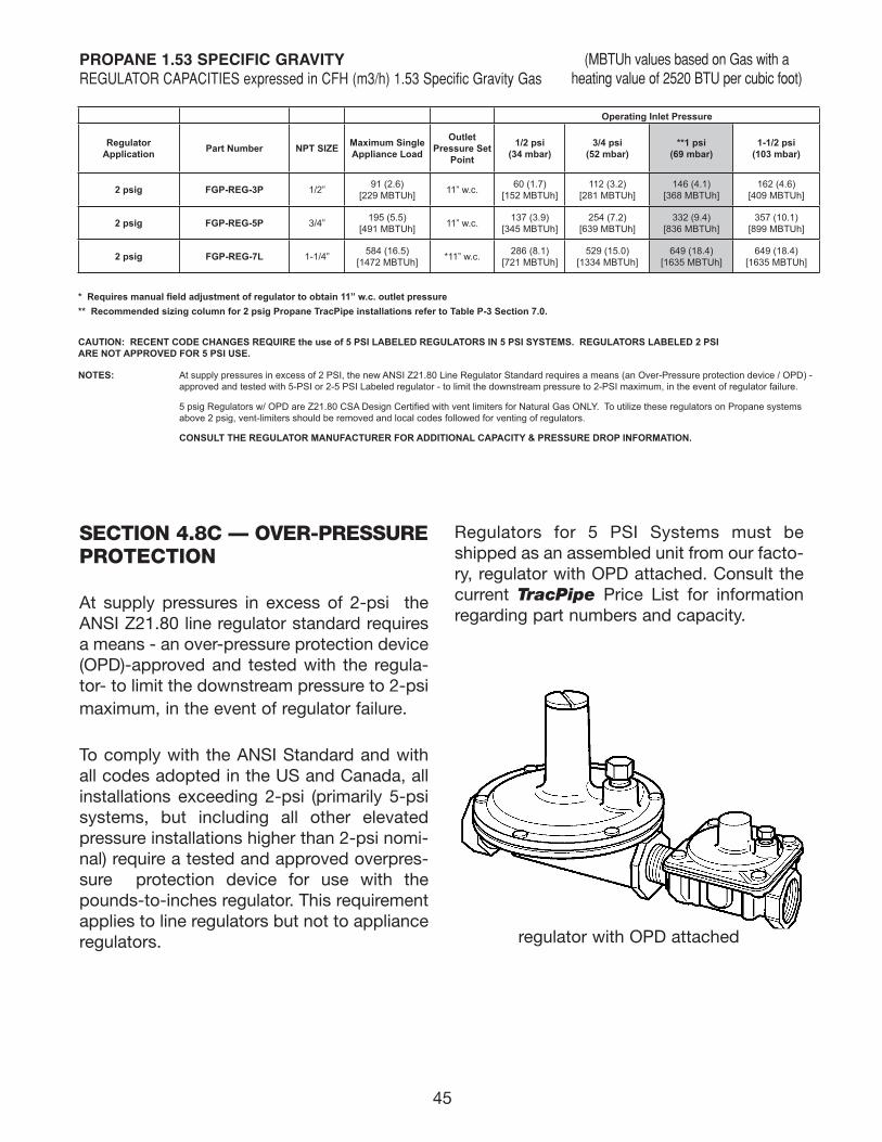
SECTION 4.8C — OVER-PRESSUREPROTECTION
At supply pressures in excess of 2-psi theANSI Z21.80 line regulator standard requiresa means - an over-pressure protection device(OPD)-approved and tested with the regula-tor- to limit the downstream pressure to 2-psimaximum, in the event of regulator failure.
To comply with the ANSI Standard and withall codes adopted in the US and Canada, allinstallations exceeding 2-psi (primarily 5-psisystems, but including all other elevatedpressure installations higher than 2-psi nomi-nal) require a tested and approved overpres-sure protection device for use with thepounds-to-inches regulator. This requirementapplies to line regulators but not to applianceregulators.
Regulators for 5 PSI Systems must beshipped as an assembled unit from our facto-ry, regulator with OPD attached. Consult thecurrent TracPipe Price List for informationregarding part numbers and capacity.
regulator with OPD attached
45
Operating Inlet Pressure
Regulator Application Part Number NPT SIZE Maximum Single
Appliance Load
Outlet Pressure Set
Point
1/2 psi (34 mbar)
3/4 psi (52 mbar)
**1 psi (69 mbar)
1-1/2 psi (103 mbar)
2 psig FGP-REG-3P 1/2” 91 (2.6) [229 MBTUh] 11” w.c. 60 (1.7)
[152 MBTUh]112 (3.2)
[281 MBTUh]146 (4.1)
[368 MBTUh]162 (4.6)
[409 MBTUh]
2 psig FGP-REG-5P 3/4” 195 (5.5) [491 MBTUh] 11” w.c. 137 (3.9)
[345 MBTUh]254 (7.2)
[639 MBTUh]332 (9.4)
[836 MBTUh]357 (10.1)
[899 MBTUh]
2 psig FGP-REG-7L 1-1/4” 584 (16.5) [1472 MBTUh] *11” w.c. 286 (8.1)
[721 MBTUh]529 (15.0)
[1334 MBTUh]649 (18.4)
[1635 MBTUh]649 (18.4)
[1635 MBTUh]
* Requires manual field adjustment of regulator to obtain 11” w.c. outlet pressure** Recommended sizing column for 2 psig Propane TracPipe installations refer to Table P-3 Section 7.0.
CAUTION: RECENT CODE CHANGES REQUIRE the use of 5 PSI LABELED REGULATORS IN 5 PSI SYSTEMS. REGULATORS LABELED 2 PSI ARE NOT APPROVED FOR 5 PSI USE.
NOTES: At supply pressures in excess of 2 PSI, the new ANSI Z21.80 Line Regulator Standard requires a means (an Over-Pressure protection device / OPD) - approved and tested with 5-PSI or 2-5 PSI Labeled regulator - to limit the downstream pressure to 2-PSI maximum, in the event of regulator failure.
5 psig Regulators w/ OPD are Z21.80 CSA Design Certified with vent limiters for Natural Gas ONLY. To utilize these regulators on Propane systems above 2 psig, vent-limiters should be removed and local codes followed for venting of regulators.
CONSULT THE REGULATOR MANUFACTURER FOR ADDITIONAL CAPACITY & PRESSURE DROP INFORMATION.
PROPANE 1.53 SPECIFIC GRAVITY REGULATOR CAPACITIES expressed in CFH (m3/h) 1.53 Specific Gravity Gas
(MBTUh values based on Gas with aheating value of 2520 BTU per cubic foot)
111743_OmegaFlex_Txt:111743_OmegaFlex_Txt 5/28/09 11:57 AM Page 45
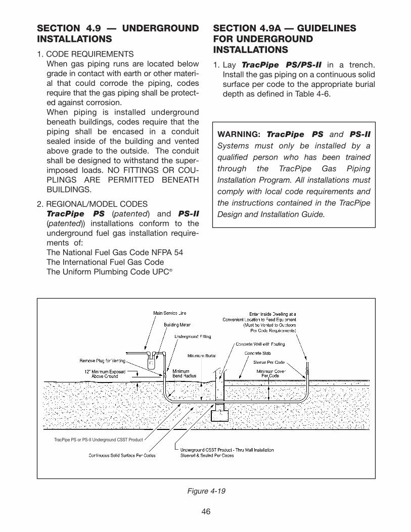
46
SECTION 4.9 — UNDERGROUNDINSTALLATIONS
1. CODE REQUIREMENTSWhen gas piping runs are located belowgrade in contact with earth or other materi-al that could corrode the piping, codesrequire that the gas piping shall be protect-ed against corrosion. When piping is installed undergroundbeneath buildings, codes require that thepiping shall be encased in a conduitsealed inside of the building and ventedabove grade to the outside. The conduitshall be designed to withstand the super-imposed loads. NO FITTINGS OR COU-PLINGS ARE PERMITTED BENEATHBUILDINGS.
2. REGIONAL/MODEL CODESTracPipe PS (patented) and PS-II(patented)) installations conform to theunderground fuel gas installation require-ments of:The National Fuel Gas Code NFPA 54The International Fuel Gas CodeThe Uniform Plumbing Code UPC®
TracPipe PS or PS-II Underground CSST Product
Figure 4-19
SECTION 4.9A — GUIDELINESFOR UNDERGROUND INSTALLATIONS
1. Lay TracPipe PS/PS-II in a trench.Install the gas piping on a continuous solidsurface per code to the appropriate burialdepth as defined in Table 4-6.
WARNING: TracPipe PS and PS-IISystems must only be installed by a qualified person who has been trainedthrough the TracPipe Gas PipingInstallation Program. All installations mustcomply with local code requirements andthe instructions contained in the TracPipeDesign and Installation Guide.
111743_OmegaFlex_Txt:111743_OmegaFlex_Txt 5/28/09 11:57 AM Page 46
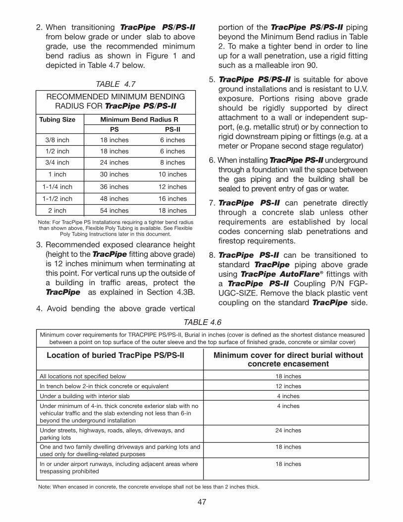
47
portion of the TracPipe PS/PS-II pipingbeyond the Minimum Bend radius in Table2. To make a tighter bend in order to lineup for a wall penetration, use a rigid fittingsuch as a malleable iron 90.
5. TracPipe PS/PS-II is suitable for aboveground installations and is resistant to U.V.exposure. Portions rising above gradeshould be rigidly supported by directattachment to a wall or independent sup-port, (e.g. metallic strut) or by connection torigid downstream piping or fittings (e.g. at ameter or Propane second stage regulator)
6. When installing TracPipe PS-II undergroundthrough a foundation wall the space betweenthe gas piping and the building shall besealed to prevent entry of gas or water.
7. TracPipe PS-II can penetrate directlythrough a concrete slab unless otherrequirements are established by localcodes concerning slab penetrations andfirestop requirements.
8. TracPipe PS-II can be transitioned tostandard TracPipe piping above gradeusing TracPipe AutoFlare® fittings witha TracPipe PS-II Coupling P/N FGP-UGC-SIZE. Remove the black plastic vent coupling on the standard TracPipe side.
TABLE 4.6
Minimum cover requirements for TRACPIPE PS/PS-II, Burial in inches (cover is defined as the shortest distance measuredbetween a point on top surface of the outer sleeve and the top surface of finished grade, concrete or similar cover)
Location of buried TracPipe PS/PS-II Minimum cover for direct burial without concrete encasement
All locations not specified below 18 inches
In trench below 2-in thick concrete or equivalent 12 inches
Under a building with interior slab 4 inches
Under minimum of 4-in. thick concrete exterior slab with no 4 inches vehicular traffic and the slab extending not less than 6-in beyond the underground installation
Under streets, highways, roads, alleys, driveways, and 24 inchesparking lots
One and two family dwelling driveways and parking lots and 18 inchesused only for dwelling-related purposes
In or under airport runways, including adjacent areas where 18 inchestrespassing prohibited
Note: When encased in concrete, the concrete envelope shall not be less than 2 inches thick.
2. When transitioning TracPipe PS/PS-IIfrom below grade or under slab to abovegrade, use the recommended minimumbend radius as shown in Figure 1 anddepicted in Table 4.7 below.
TABLE 4.7
RECOMMENDED MINIMUM BENDINGRADIUS FOR TracPipe PS/PS-II
Tubing Size Minimum Bend Radius R
PS PS-II
3/8 inch 18 inches 6 inches
1/2 inch 18 inches 6 inches
3/4 inch 24 inches 8 inches
1 inch 30 inches 10 inches
1-1/4 inch 36 inches 12 inches
1-1/2 inch 48 inches 16 inches
2 inch 54 inches 18 inches
Note: For TracPipe PS Installations requiring a tighter bend radiusthan shown above, Flexible Poly Tubing is available. See Flexible
Poly Tubing Instructions later in this document.
3. Recommended exposed clearance height(height to the TracPipe fitting above grade)is 12 inches minimum when terminating atthis point. For vertical runs up the outside ofa building in traffic areas, protect theTracPipe as explained in Section 4.3B.
4. Avoid bending the above grade vertical
111743_OmegaFlex_Txt:111743_OmegaFlex_Txt 5/28/09 11:57 AM Page 47
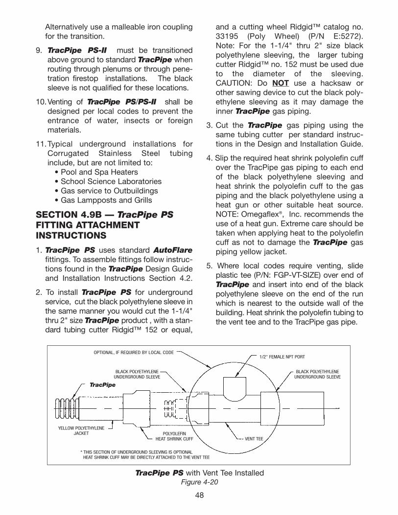
TracPipe PS with Vent Tee InstalledFigure 4-20
TracPipe
OPTIONAL, IF REQUIRED BY LOCAL CODE
BLACK POLYETHYLENE UNDERGROUND SLEEVE
* THIS SECTION OF UNDERGROUND SLEEVING IS OPTIONALHEAT SHRINK CUFF MAY BE DIRECTLY ATTACHED TO THE VENT TEE
YELLOW POLYETHYLENE JACKET POLYOLEFIN
HEAT SHRINK CUFF VENT TEE
1/2" FEMALE NPT PORT
BLACK POLYETHYLENE UNDERGROUND SLEEVE
and a cutting wheel Ridgid™ catalog no.33195 (Poly Wheel) (P/N E:5272). Note: For the 1-1/4" thru 2" size blackpolyethylene sleeving, the larger tubingcutter Ridgid™ no. 152 must be used dueto the diameter of the sleeving.CAUTION: Do NOT use a hacksaw orother sawing device to cut the black poly-ethylene sleeving as it may damage theinner TracPipe gas piping.
3. Cut the TracPipe gas piping using thesame tubing cutter per standard instruc-tions in the Design and Installation Guide.
4. Slip the required heat shrink polyolefin cuffover the TracPipe gas piping to each endof the black polyethylene sleeving andheat shrink the polyolefin cuff to the gaspiping and the black polyethylene using aheat gun or other suitable heat source.NOTE: Omegaflex®, Inc. recommends theuse of a heat gun. Extreme care should betaken when applying heat to the polyolefincuff as not to damage the TracPipe gaspiping yellow jacket.
5. Where local codes require venting, slideplastic tee (P/N: FGP-VT-SIZE) over end ofTracPipe and insert into end of the blackpolyethylene sleeve on the end of the runwhich is nearest to the outside wall of thebuilding. Heat shrink the polyolefin tubing tothe vent tee and to the TracPipe gas pipe.
Alternatively use a malleable iron couplingfor the transition.
9. TracPipe PS-II must be transitionedabove ground to standard TracPipe whenrouting through plenums or through pene-tration firestop installations. The blacksleeve is not qualified for these locations.
10.Venting of TracPipe PS/PS-II shall bedesigned per local codes to prevent theentrance of water, insects or foreign materials.
11.Typical underground installations forCorrugated Stainless Steel tubinginclude, but are not limited to:
• Pool and Spa Heaters • School Science Laboratories • Gas service to Outbuildings• Gas Lampposts and Grills
SECTION 4.9B — TracPipe PSFITTING ATTACHMENT INSTRUCTIONS
1. TracPipe PS uses standard AutoFlarefittings. To assemble fittings follow instruc-tions found in the TracPipe Design Guideand Installation Instructions Section 4.2.
2. To install TracPipe PS for underground service, cut the black polyethylene sleeve inthe same manner you would cut the 1-1/4"thru 2" size TracPipe product , with a stan-dard tubing cutter Ridgid™ 152 or equal,
48
111743_OmegaFlex_Txt:111743_OmegaFlex_Txt 5/28/09 11:57 AM Page 48
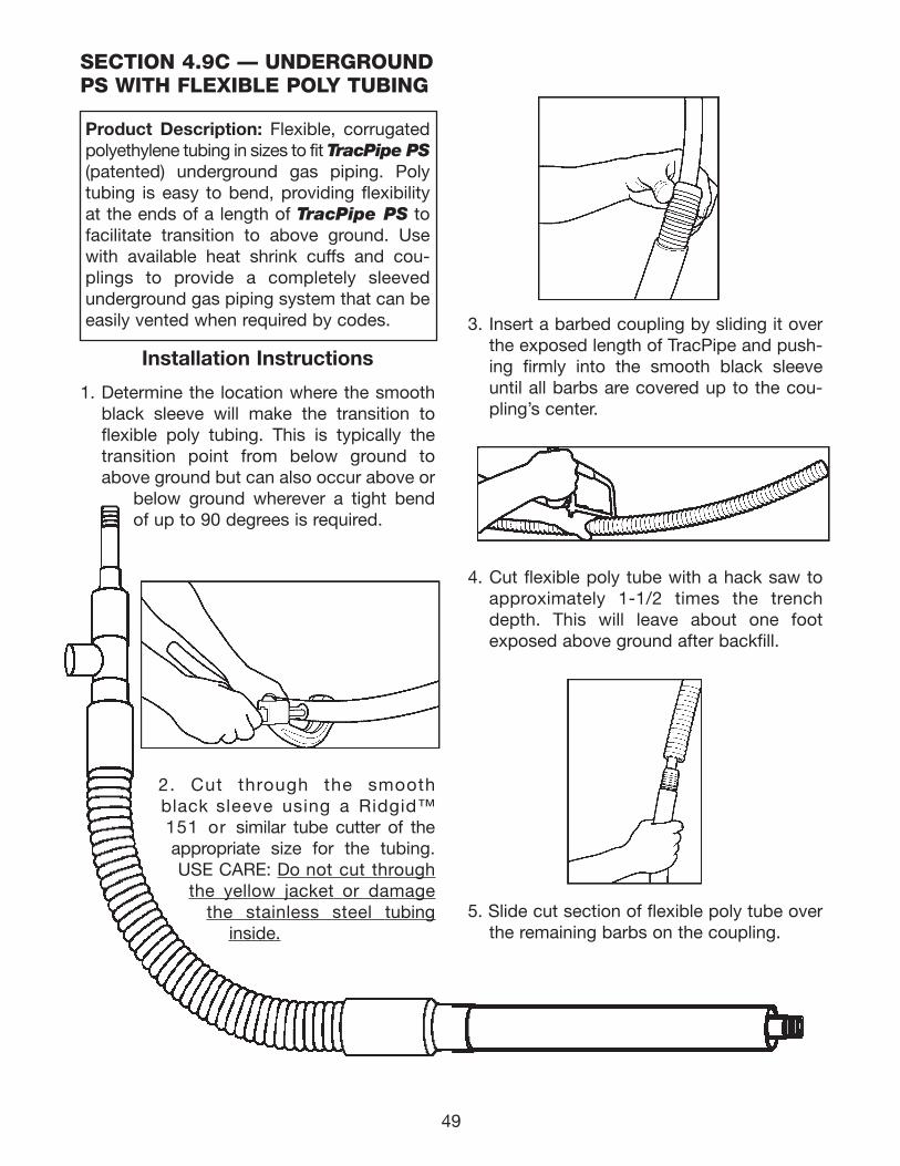
3. Insert a barbed coupling by sliding it overthe exposed length of TracPipe and push-ing firmly into the smooth black sleeveuntil all barbs are covered up to the cou-pling’s center.
4. Cut flexible poly tube with a hack saw toapproximately 1-1/2 times the trenchdepth. This will leave about one footexposed above ground after backfill.
5. Slide cut section of flexible poly tube overthe remaining barbs on the coupling.
SECTION 4.9C — UNDERGROUNDPS WITH FLEXIBLE POLY TUBING
Product Description: Flexible, corrugatedpolyethylene tubing in sizes to fit TracPipe PS(patented) underground gas piping. Polytubing is easy to bend, providing flexibilityat the ends of a length of TracPipe PS tofacilitate transition to above ground. Usewith available heat shrink cuffs and cou-plings to provide a completely sleevedunderground gas piping system that can beeasily vented when required by codes.
Installation Instructions
1. Determine the location where the smoothblack sleeve will make the transition to flexible poly tubing. This is typically thetransition point from below ground toabove ground but can also occur above or
below ground wherever a tight bendof up to 90 degrees is required.
2. Cut through the smoothblack sleeve using a Ridgid™151 or similar tube cutter of theappropriate size for the tubing.USE CARE: Do not cut through
the yellow jacket or damagethe stainless steel tubing
inside.
49
111743_OmegaFlex_Txt:111743_OmegaFlex_Txt 5/28/09 11:57 AM Page 49
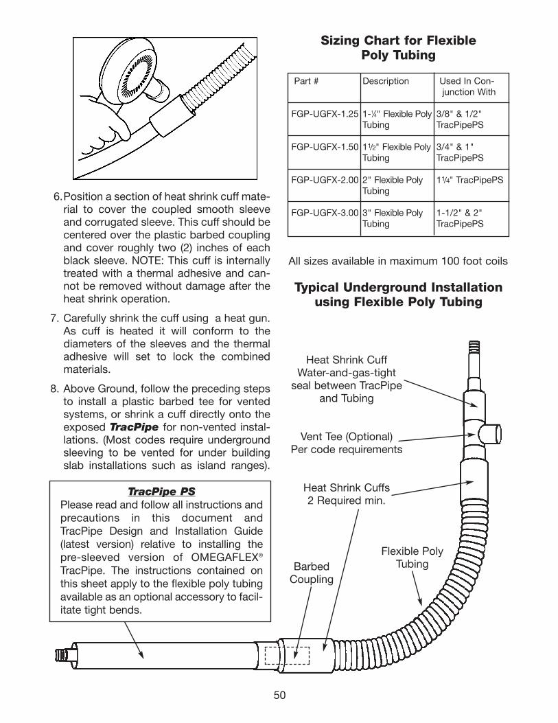
50
6.Position a section of heat shrink cuff mate-rial to cover the coupled smooth sleeveand corrugated sleeve. This cuff should becentered over the plastic barbed couplingand cover roughly two (2) inches of eachblack sleeve. NOTE: This cuff is internallytreated with a thermal adhesive and can-not be removed without damage after theheat shrink operation.
7. Carefully shrink the cuff using a heat gun.As cuff is heated it will conform to thediameters of the sleeves and the thermaladhesive will set to lock the combinedmaterials.
8. Above Ground, follow the preceding stepsto install a plastic barbed tee for ventedsystems, or shrink a cuff directly onto theexposed TracPipe for non-vented instal-lations. (Most codes require undergroundsleeving to be vented for under buildingslab installations such as island ranges).
Sizing Chart for Flexible Poly Tubing
Part # Description Used In Con-junction With
FGP-UGFX-1.25 1-1⁄4" Flexible Poly 3/8" & 1/2"Tubing TracPipePS
FGP-UGFX-1.50 11/2" Flexible Poly 3/4" & 1" Tubing TracPipePS
FGP-UGFX-2.00 2" Flexible Poly 11/4" TracPipePSTubing
FGP-UGFX-3.00 3" Flexible Poly 1-1/2" & 2" Tubing TracPipePS
All sizes available in maximum 100 foot coils
Typical Underground Installationusing Flexible Poly Tubing
Heat Shrink CuffWater-and-gas-tight
seal between TracPipeand Tubing
Vent Tee (Optional)Per code requirements
Heat Shrink Cuffs2 Required min.
BarbedCoupling
Flexible PolyTubing
TracPipe PSPlease read and follow all instructions andprecautions in this document andTracPipe Design and Installation Guide(latest version) relative to installing thepre-sleeved version of OMEGAFLEX®
TracPipe. The instructions contained onthis sheet apply to the flexible poly tubingavailable as an optional accessory to facil-itate tight bends.
111743_OmegaFlex_Txt:111743_OmegaFlex_Txt 5/28/09 11:57 AM Page 50
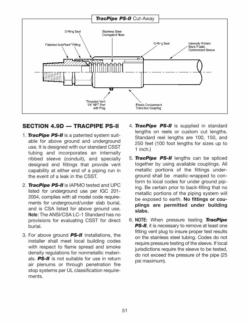
51
SECTION 4.9D — TRACPIPE PS-II
1. TracPipe PS-II is a patented system suit-able for above ground and undergrounduse. It is designed with our standard CSSTtubing and incorporates an internallyribbed sleeve (conduit), and speciallydesigned end fittings that provide ventcapability at either end of a piping run inthe event of a leak in the CSST.
2. TracPipe PS-II is IAPMO tested and UPClisted for underground use per IGC 201-2004, complies with all model code require-ments for underground/under slab burial,and is CSA listed for above ground use.Note: The ANSI/CSA LC-1 Standard has noprovisions for evaluating CSST for directburial.
3. For above ground PS-II installations, theinstaller shall meet local building codeswith respect to flame spread and smokedensity regulations for nonmetallic materi-als. PS-II is not suitable for use in returnair plenums or through penetration firestop systems per UL classification require-ments.
TracPipe PS-II Cut-Away
4. TracPipe PS-II is supplied in standardlengths on reels or custom cut lengths.Standard reel lengths are 100, 150, and250 feet (100 foot lengths for sizes up to 1 inch.)
5. TracPipe PS-II lengths can be splicedtogether by using available couplings. Allmetallic portions of the fittings under-ground shall be mastic-wrapped to con-form to local codes for under ground pip-ing. Be certain prior to back-filling that nometallic portions of the piping system willbe exposed to earth. No fittings or cou-plings are permitted under buildingslabs.
6. NOTE: When pressure testing TracPipe PS-II, it is necessary to remove at least onefitting vent plug to insure proper test resultson the stainless steel tubing. Codes do notrequire pressure testing of the sleeve. If localjurisdictions require the sleeve to be tested,do not exceed the pressure of the pipe (25psi maximum).
111743_OmegaFlex_Txt:111743_OmegaFlex_Txt 5/28/09 11:57 AM Page 51
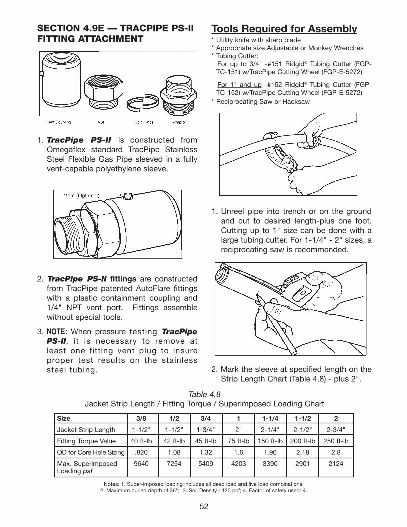
52
Tools Required for Assembly* Utility knife with sharp blade* Appropriate size Adjustable or Monkey Wrenches* Tubing Cutter:
For up to 3/4" -#151 Ridgid® Tubing Cutter (FGP-TC-151) w/TracPipe Cutting Wheel (FGP-E-5272)
For 1" and up -#152 Ridgid® Tubing Cutter (FGP-TC-152) w/TracPipe Cutting Wheel (FGP-E-5272)
* Reciprocating Saw or Hacksaw
1. Unreel pipe into trench or on the groundand cut to desired length-plus one foot.Cutting up to 1" size can be done with alarge tubing cutter. For 1-1/4" - 2" sizes, areciprocating saw is recommended.
2. Mark the sleeve at specified length on theStrip Length Chart (Table 4.8) - plus 2".
SECTION 4.9E — TRACPIPE PS-IIFITTING ATTACHMENT
1. TracPipe PS-II is constructed fromOmegaflex standard TracPipe StainlessSteel Flexible Gas Pipe sleeved in a fullyvent-capable polyethylene sleeve.
2. TracPipe PS-II fittings are constructedfrom TracPipe patented AutoFlare fittingswith a plastic containment coupling and1/4" NPT vent port. Fittings assemble without special tools.
3. NOTE: When pressure testing TracPipePS-II, it is necessary to remove atleast one fitting vent plug to insureproper test results on the stainlesssteel tubing.
Table 4.8Jacket Strip Length / Fitting Torque / Superimposed Loading Chart
Size 3/8 1/2 3/4 1 1-1/4 1-1/2 2
Jacket Strip Length 1-1/2" 1-1/2" 1-3/4" 2" 2-1/4" 2-1/2" 2-3/4"
Fitting Torque Value 40 ft-lb 42 ft-lb 45 ft-lb 75 ft-lb 150 ft-lb 200 ft-lb 250 ft-lb
OD for Core Hole Sizing .820 1.08 1.32 1.6 1.96 2.18 2.8
Max. Superimposed 9640 7254 5409 4203 3390 2901 2124Loading psf
Notes: 1. Super-imposed loading includes all dead load and live load combinations.2. Maximum buried depth of 36"; 3. Soil Density : 120 pcf; 4. Factor of safety used: 4.
111743_OmegaFlex_Txt:111743_OmegaFlex_Txt 5/28/09 11:57 AM Page 52
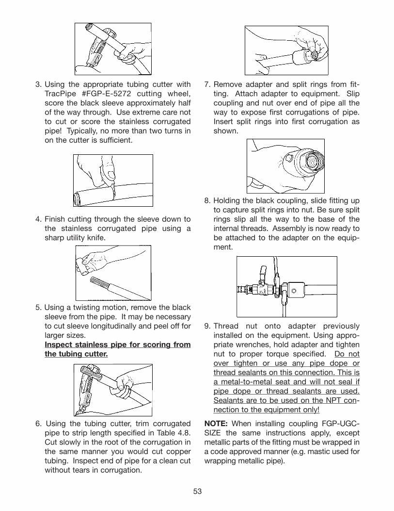
53
7. Remove adapter and split rings from fit-ting. Attach adapter to equipment. Slipcoupling and nut over end of pipe all theway to expose first corrugations of pipe.Insert split rings into first corrugation asshown.
8. Holding the black coupling, slide fitting upto capture split rings into nut. Be sure splitrings slip all the way to the base of theinternal threads. Assembly is now ready tobe attached to the adapter on the equip-ment.
9. Thread nut onto adapter previouslyinstalled on the equipment. Using appro-priate wrenches, hold adapter and tightennut to proper torque specified. Do notover tighten or use any pipe dope orthread sealants on this connection. This isa metal-to-metal seat and will not seal ifpipe dope or thread sealants are used.Sealants are to be used on the NPT con-nection to the equipment only!
NOTE: When installing coupling FGP-UGC-SIZE the same instructions apply, exceptmetallic parts of the fitting must be wrapped ina code approved manner (e.g. mastic used forwrapping metallic pipe).
3. Using the appropriate tubing cutter withTracPipe #FGP-E-5272 cutting wheel,score the black sleeve approximately halfof the way through. Use extreme care notto cut or score the stainless corrugatedpipe! Typically, no more than two turns inon the cutter is sufficient.
4. Finish cutting through the sleeve down tothe stainless corrugated pipe using asharp utility knife.
5. Using a twisting motion, remove the blacksleeve from the pipe. It may be necessaryto cut sleeve longitudinally and peel off forlarger sizes. Inspect stainless pipe for scoring fromthe tubing cutter.
6. Using the tubing cutter, trim corrugatedpipe to strip length specified in Table 4.8.Cut slowly in the root of the corrugation inthe same manner you would cut coppertubing. Inspect end of pipe for a clean cutwithout tears in corrugation.
111743_OmegaFlex_Txt:111743_OmegaFlex_Txt 5/28/09 11:57 AM Page 53
SECTION 4.10 — ELECTRICALBONDING/GROUNDING
1. Definitions:Grounding: The process of making anelectrical connection to the general massof the earth. This is most often accom-plished with ground rods, ground mats orsome other grounding system. Low resis-tance grounding is critical to the opera-tion of lightning protection techniques.
Bonding: The process of making an elec-trical connection between the groundingelectrode and any equipment, appliance,or metal conductor: pipes, plumbing,flues, etc. Equipment bonding serves toprotect people and equipment in theevent of an electrical fault.
Equipotential Bonding: The process ofmaking an electrical connection betweenthe grounding electrode and any metalconductor: pipes, plumbing, flues, etc.,which may be exposed to a lightningstrike and can be a conductive path forlightning energy towards or away from thegrounding electrode.
2. The TracPipe® gas piping system shall bebonded in accordance with these instruc-tions and the National Fuel Gas Code, NFPA54/ANSI Z223. In the event of a conflictbetween these instructions and local codes,the local codes shall control. The piping sys-tem is not to be used as a grounding con-ductor or electrode for an electrical system.
WARNING!FIRE / FUEL GAS PIPING
The TracPipe® flexible gas piping MUST bebonded to an effective ground-fault currentpath per NFPA 54 in accordance with theinstructions contained in this section.
It is HIGHLY RECOMMENDED to equipo-tentially bond all mechanical systems to thebuilding’s grounding electrode.
!
54
SECTION 4.10A COUNTERSTRIKE®
INSTALLATION INSTRUCTIONSfor all products date coded 0731 andhigher (manufactured after July 30, 2007)
1. CounterStrike® CSST with the black,protective sleeve uses the same easy toinstall AutoFlare® fittings as conventionalTracPipe® with the yellow jacket.CounterStrike® systems are sized in thesame manner as TracPipe® either usingcapacity tables or other approved methods.
2. The instructions for cutting the tubingand for making fitting connections toCounterStrike® are identical to standardyellow-jacketed TracPipe®. The jacketshall remain intact as much as practicalwhen attaching the fitting.
3. Unlike TracPipe®, there are no additionalbonding requirements for CounterStrike®
imposed by the manufacturer’s installa-tion instructions. CounterStrike® is tobe bonded in accordance with theNational Electrical Code NFPA 70 Article250.104 in the same manner as the mini-mum requirements for rigid metal piping.However, installers must always adhere toany local requirements that may conflictwith these instructions.
4. CounterStrike® meets building coderequirements (ASTM E84) with respect toflame spread and smoke density. Thispermits installation in drop ceilings usedas return air plenums.
5. CounterStrike® has thru penetration ULclassifications for 1, 2 and 4 hours withthe black jacket intact.
111743_OmegaFlex_Txt:111743_OmegaFlex_Txt 5/28/09 11:57 AM Page 54
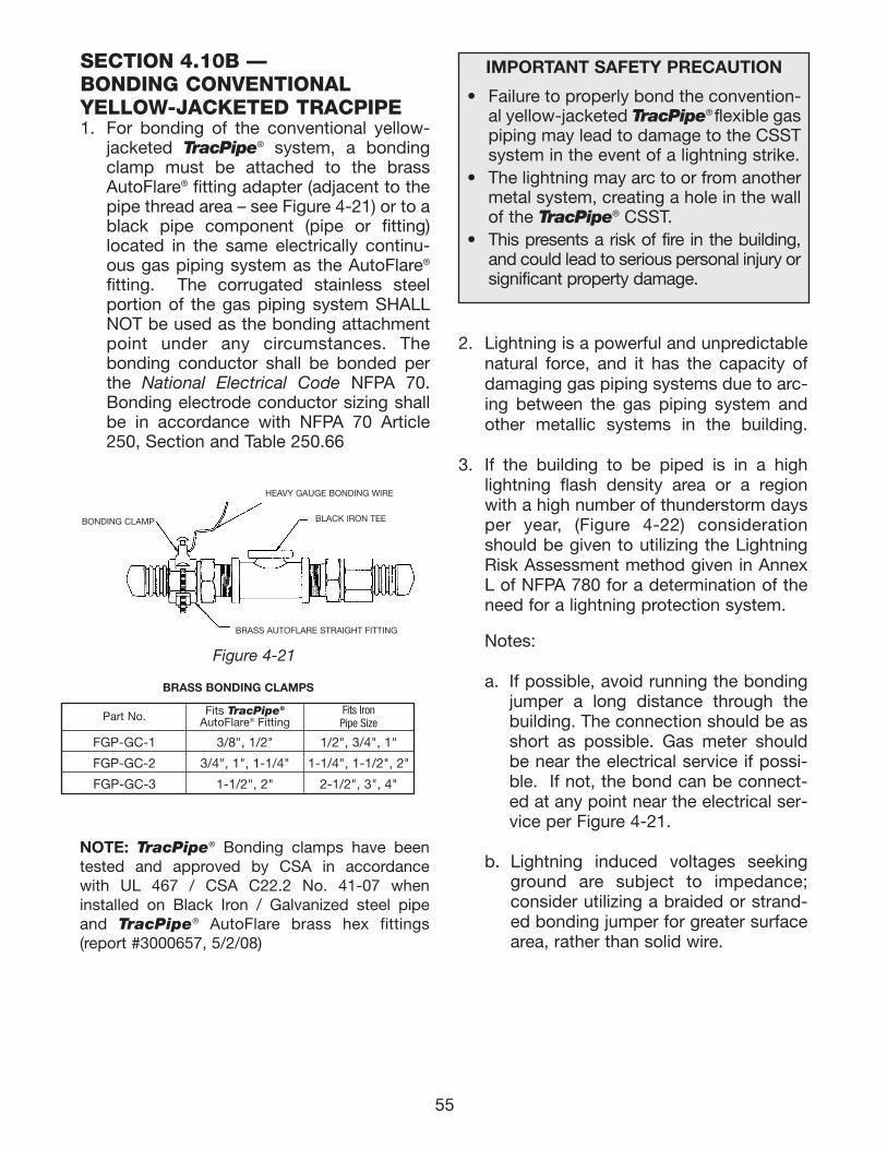
55
2. Lightning is a powerful and unpredictablenatural force, and it has the capacity ofdamaging gas piping systems due to arc-ing between the gas piping system andother metallic systems in the building.
3. If the building to be piped is in a highlightning flash density area or a regionwith a high number of thunderstorm daysper year, (Figure 4-22) considerationshould be given to utilizing the LightningRisk Assessment method given in AnnexL of NFPA 780 for a determination of theneed for a lightning protection system.
Notes:
a. If possible, avoid running the bondingjumper a long distance through thebuilding. The connection should be asshort as possible. Gas meter shouldbe near the electrical service if possi-ble. If not, the bond can be connect-ed at any point near the electrical ser-vice per Figure 4-21.
b. Lightning induced voltages seekingground are subject to impedance;consider utilizing a braided or strand-ed bonding jumper for greater surfacearea, rather than solid wire.
SECTION 4.10B — BONDING CONVENTIONAL YELLOW-JACKETED TRACPIPE1. For bonding of the conventional yellow-
jacketed TracPipe® system, a bondingclamp must be attached to the brassAutoFlare® fitting adapter (adjacent to thepipe thread area – see Figure 4-21) or to ablack pipe component (pipe or fitting)located in the same electrically continu-ous gas piping system as the AutoFlare®
fitting. The corrugated stainless steelportion of the gas piping system SHALLNOT be used as the bonding attachmentpoint under any circumstances. Thebonding conductor shall be bonded perthe National Electrical Code NFPA 70.Bonding electrode conductor sizing shallbe in accordance with NFPA 70 Article250, Section and Table 250.66
Figure 4-21
Part No.
FGP-GC-1
FGP-GC-2
FGP-GC-3
1/2", 3/4", 1"
1-1/4", 1-1/2", 2"
2-1/2", 3", 4"
3/8", 1/2"
3/4", 1", 1-1/4"
1-1/2", 2"
Fits IronPipe Size
Fits TracPipe®
AutoFlare® Fitting
BRASS BONDING CLAMPS
BONDING CLAMP
BRASS AUTOFLARE STRAIGHT FITTING
BLACK IRON TEE
HEAVY GAUGE BONDING WIRE
IMPORTANT SAFETY PRECAUTION
• Failure to properly bond the convention-al yellow-jacketed TracPipe® flexible gaspiping may lead to damage to the CSSTsystem in the event of a lightning strike.
• The lightning may arc to or from anothermetal system, creating a hole in the wallof the TracPipe® CSST.
• This presents a risk of fire in the building,and could lead to serious personal injury orsignificant property damage.
NOTE: TracPipe® Bonding clamps have beentested and approved by CSA in accordance with UL 467 / CSA C22.2 No. 41-07 wheninstalled on Black Iron / Galvanized steel pipeand TracPipe® AutoFlare brass hex fittings(report #3000657, 5/2/08)
111743_OmegaFlex_Txt:111743_OmegaFlex_Txt 5/28/09 11:57 AM Page 55
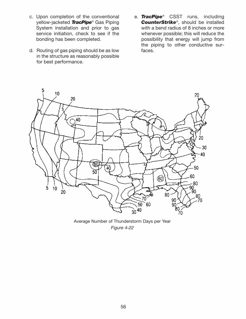
56
Average Number of Thunderstorm Days per Year
Figure 4-22
c. Upon completion of the conventionalyellow-jacketed TracPipe® Gas PipingSystem installation and prior to gasservice initiation, check to see if thebonding has been completed.
d. Routing of gas piping should be as lowin the structure as reasonably possiblefor best performance.
e. TracPipe® CSST runs, includingCounterStrike®, should be installedwith a bend radius of 8 inches or morewhenever possible; this will reduce thepossibility that energy will jump fromthe piping to other conductive sur-faces.
111743_OmegaFlex_Txt:111743_OmegaFlex_Txt 5/28/09 11:57 AM Page 56
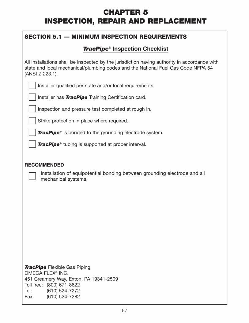
CHAPTER 5INSPECTION, REPAIR AND REPLACEMENT
SECTION 5.1 — MINIMUM INSPECTION REQUIREMENTS
TracPipe® Inspection Checklist
All installations shall be inspected by the jurisdiction having authority in accordance with state and local mechanical/plumbing codes and the National Fuel Gas Code NFPA 54 (ANSI Z 223.1).
Installer qualified per state and/or local requirements.
Installer has TracPipe Training Certification card.
Inspection and pressure test completed at rough in.
Strike protection in place where required.
TracPipe® is bonded to the grounding electrode system.
TracPipe® tubing is supported at proper interval.
RECOMMENDED
Installation of equipotential bonding between grounding electrode and all mechanical systems.
TracPipe Flexible Gas PipingOMEGA FLEX® INC.451 Creamery Way, Exton, PA 19341-2509Toll free: (800) 671-8622Tel: (610) 524-7272Fax: (610) 524-7282
57
111743_OmegaFlex_Txt:111743_OmegaFlex_Txt 5/28/09 11:57 AM Page 57
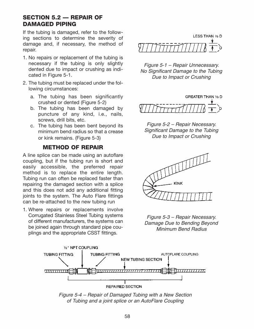
58
SECTION 5.2 — REPAIR OFDAMAGED PIPINGIf the tubing is damaged, refer to the follow-ing sections to determine the severity ofdamage and, if necessary, the method ofrepair.
1. No repairs or replacement of the tubing isnecessary if the tubing is only slightlydented due to impact or crushing as indi-cated in Figure 5-1.
2. The tubing must be replaced under the fol-lowing circumstances:
a. The tubing has been significantlycrushed or dented (Figure 5-2)
b. The tubing has been damaged bypuncture of any kind, i.e., nails,screws, drill bits, etc.
c. The tubing has been bent beyond itsminimum bend radius so that a creaseor kink remains. (Figure 5-3)
METHOD OF REPAIRA line splice can be made using an autoflarecoupling, but if the tubing run is short andeasily accessible, the preferred repairmethod is to replace the entire length.Tubing run can often be replaced faster thanrepairing the damaged section with a spliceand this does not add any additional fittingjoints to the system. The Auto Flare fittingscan be re-attached to the new tubing run
1. Where repairs or replacements involveCorrugated Stainless Steel Tubing systemsof different manufacturers, the systems canbe joined again through standard pipe cou-plings and the appropriate CSST fittings.
Figure 5-2 – Repair Necessary.Significant Damage to the Tubing
Due to Impact or Crushing
Figure 5-3 – Repair Necessary.Damage Due to Bending Beyond
Minimum Bend Radius
Figure 5-4 – Repair of Damaged Tubing with a New Sectionof Tubing and a joint splice or an AutoFlare Coupling
Figure 5-1 – Repair Unnecessary.No Significant Damage to the Tubing
Due to Impact or Crushing
111743_OmegaFlex_Txt:111743_OmegaFlex_Txt 5/28/09 11:57 AM Page 58
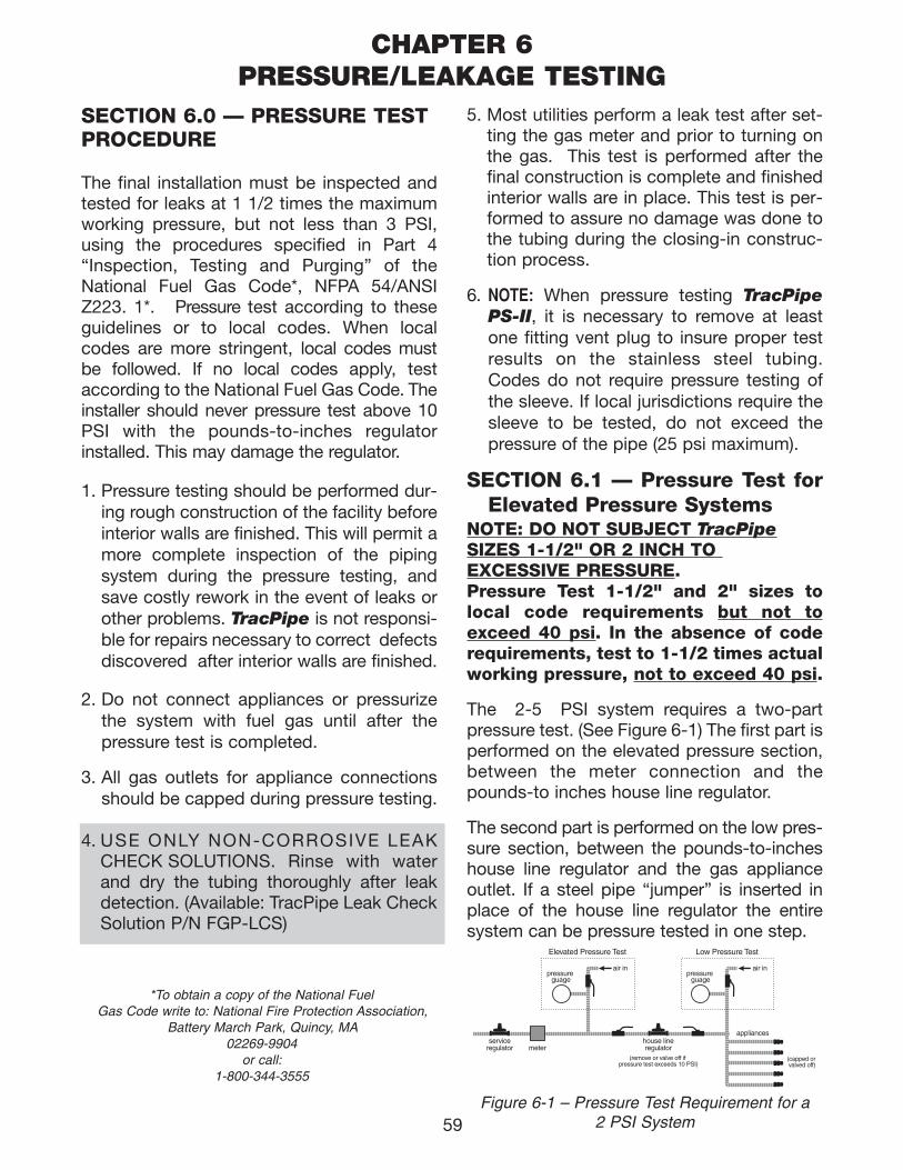
59
*To obtain a copy of the National FuelGas Code write to: National Fire Protection Association,
Battery March Park, Quincy, MA02269-9904
or call:1-800-344-3555
5. Most utilities perform a leak test after set-ting the gas meter and prior to turning onthe gas. This test is performed after thefinal construction is complete and finishedinterior walls are in place. This test is per-formed to assure no damage was done tothe tubing during the closing-in construc-tion process.
6. NOTE: When pressure testing TracPipePS-II, it is necessary to remove at leastone fitting vent plug to insure proper testresults on the stainless steel tubing.Codes do not require pressure testing ofthe sleeve. If local jurisdictions require thesleeve to be tested, do not exceed thepressure of the pipe (25 psi maximum).
SECTION 6.1 — Pressure Test forElevated Pressure Systems
NOTE: DO NOT SUBJECT TracPipeSIZES 1-1/2" OR 2 INCH TO EXCESSIVE PRESSURE.Pressure Test 1-1/2" and 2" sizes tolocal code requirements but not toexceed 40 psi. In the absence of coderequirements, test to 1-1/2 times actualworking pressure, not to exceed 40 psi.
The 2-5 PSI system requires a two-partpressure test. (See Figure 6-1) The first part isperformed on the elevated pressure section,between the meter connection and thepounds-to inches house line regulator.
The second part is performed on the low pres-sure section, between the pounds-to-incheshouse line regulator and the gas applianceoutlet. If a steel pipe “jumper” is inserted inplace of the house line regulator the entire system can be pressure tested in one step.
air in
Elevated Pressure Test
pressure guage
Low Pressure Test
serviceregulator meter
house lineregulator
(remove or valve off if pressure test exceeds 10 PSI)
air inpressure
guage
appliances
(capped or valved off)
Figure 6-1 – Pressure Test Requirement for a 2 PSI System
CHAPTER 6PRESSURE/LEAKAGE TESTING
SECTION 6.0 — PRESSURE TESTPROCEDURE
The final installation must be inspected andtested for leaks at 1 1/2 times the maximumworking pressure, but not less than 3 PSI,using the procedures specified in Part 4“Inspection, Testing and Purging” of theNational Fuel Gas Code*, NFPA 54/ANSIZ223. 1*. Pressure test according to theseguidelines or to local codes. When localcodes are more stringent, local codes mustbe followed. If no local codes apply, testaccording to the National Fuel Gas Code. Theinstaller should never pressure test above 10PSI with the pounds-to-inches regulatorinstalled. This may damage the regulator.
1. Pressure testing should be performed dur-ing rough construction of the facility beforeinterior walls are finished. This will permit amore complete inspection of the pipingsystem during the pressure testing, andsave costly rework in the event of leaks orother problems. TracPipe is not responsi-ble for repairs necessary to correct defectsdiscovered after interior walls are finished.
2. Do not connect appliances or pressurizethe system with fuel gas until after thepressure test is completed.
3. All gas outlets for appliance connectionsshould be capped during pressure testing.
4. USE ONLY NON-CORROSIVE LEAK CHECK SOLUTIONS. Rinse with waterand dry the tubing thoroughly after leakdetection. (Available: TracPipe Leak CheckSolution P/N FGP-LCS)
111743_OmegaFlex_Txt:111743_OmegaFlex_Txt 5/28/09 11:57 AM Page 59
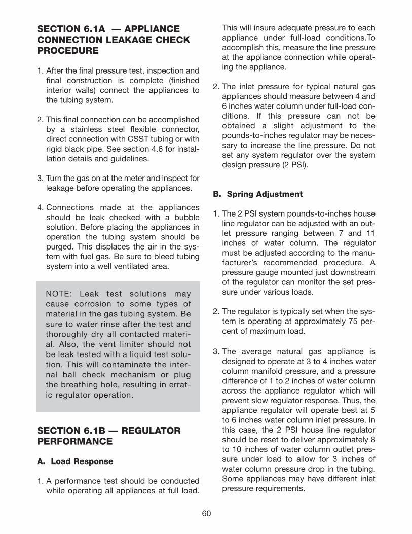
60
SECTION 6.1A — APPLIANCE CONNECTION LEAKAGE CHECKPROCEDURE
1. After the final pressure test, inspection andfinal construction is complete (finishedinterior walls) connect the appliances tothe tubing system.
2. This final connection can be accomplishedby a stainless steel flexible connector,direct connection with CSST tubing or withrigid black pipe. See section 4.6 for instal-lation details and guidelines.
3. Turn the gas on at the meter and inspect forleakage before operating the appliances.
4. Connections made at the appliancesshould be leak checked with a bubblesolution. Before placing the appliances inoperation the tubing system should bepurged. This displaces the air in the sys-tem with fuel gas. Be sure to bleed tubingsystem into a well ventilated area.
SECTION 6.1B — REGULATORPERFORMANCE
A. Load Response
1. A performance test should be conductedwhile operating all appliances at full load.
NOTE: Leak test solutions maycause corrosion to some types ofmaterial in the gas tubing system. Besure to water rinse after the test andthoroughly dry all contacted materi-al. Also, the vent limiter should notbe leak tested with a liquid test solu-tion. This will contaminate the inter-nal ball check mechanism or plugthe breathing hole, resulting in errat-ic regulator operation.
This will insure adequate pressure to eachappliance under full-load conditions.Toaccomplish this, measure the line pressureat the appliance connection while operat-ing the appliance.
2. The inlet pressure for typical natural gasappliances should measure between 4 and6 inches water column under full-load con-ditions. If this pressure can not beobtained a slight adjustment to thepounds-to-inches regulator may be neces-sary to increase the line pressure. Do notset any system regulator over the systemdesign pressure (2 PSI).
B. Spring Adjustment
1. The 2 PSI system pounds-to-inches houseline regulator can be adjusted with an out-let pressure ranging between 7 and 11inches of water column. The regulatormust be adjusted according to the manu-facturer’s recommended procedure. Apressure gauge mounted just downstreamof the regulator can monitor the set pres-sure under various loads.
2. The regulator is typically set when the sys-tem is operating at approximately 75 per-cent of maximum load.
3. The average natural gas appliance isdesigned to operate at 3 to 4 inches watercolumn manifold pressure, and a pressuredifference of 1 to 2 inches of water columnacross the appliance regulator which willprevent slow regulator response. Thus, theappliance regulator will operate best at 5to 6 inches water column inlet pressure. Inthis case, the 2 PSI house line regulatorshould be reset to deliver approximately 8to 10 inches of water column outlet pres-sure under load to allow for 3 inches ofwater column pressure drop in the tubing.Some appliances may have different inletpressure requirements.
111743_OmegaFlex_Txt:111743_OmegaFlex_Txt 5/28/09 11:57 AM Page 60
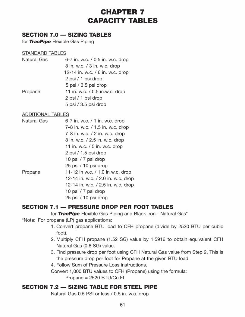
SECTION 7.0 — SIZING TABLESfor TracPipe Flexible Gas Piping
STANDARD TABLESNatural Gas 6-7 in. w.c. / 0.5 in. w.c. drop
8 in. w.c. / 3 in. w.c. drop12-14 in. w.c. / 6 in. w.c. drop2 psi / 1 psi drop5 psi / 3.5 psi drop
Propane 11 in. w.c. / 0.5 in.w.c. drop2 psi / 1 psi drop5 psi / 3.5 psi drop
ADDITIONAL TABLESNatural Gas 6-7 in. w.c. / 1 in. w.c. drop
7-8 in. w.c. / 1.5 in. w.c. drop7-8 in. w.c. / 2 in. w.c. drop 8 in. w.c. / 2.5 in. w.c. drop 11 in. w.c. / 5 in. w.c. drop2 psi / 1.5 psi drop10 psi / 7 psi drop25 psi / 10 psi drop
Propane 11-12 in w.c. / 1.0 in w.c. drop 12-14 in. w.c. / 2.0 in. w.c. drop12-14 in. w.c. / 2.5 in. w.c. drop10 psi / 7 psi drop25 psi / 10 psi drop
SECTION 7.1 — PRESSURE DROP PER FOOT TABLESfor TracPipe Flexible Gas Piping and Black Iron - Natural Gas*
*Note: For propane (LP) gas applications:1. Convert propane BTU load to CFH propane (divide by 2520 BTU per cubic
foot). 2. Multiply CFH propane (1.52 SG) value by 1.5916 to obtain equivalent CFH
Natural Gas (0.6 SG) value.3. Find pressure drop per foot using CFH Natural Gas value from Step 2. This is
the pressure drop per foot for Propane at the given BTU load.4. Follow Sum of Pressure Loss instructions.Convert 1,000 BTU values to CFH (Propane) using the formula:
Propane = 2520 BTU/Cu.Ft.
SECTION 7.2 — SIZING TABLE FOR STEEL PIPENatural Gas 0.5 PSI or less / 0.5 in. w.c. drop
61
CHAPTER 7CAPACITY TABLES
111743_OmegaFlex_Txt:111743_OmegaFlex_Txt 5/28/09 11:57 AM Page 61
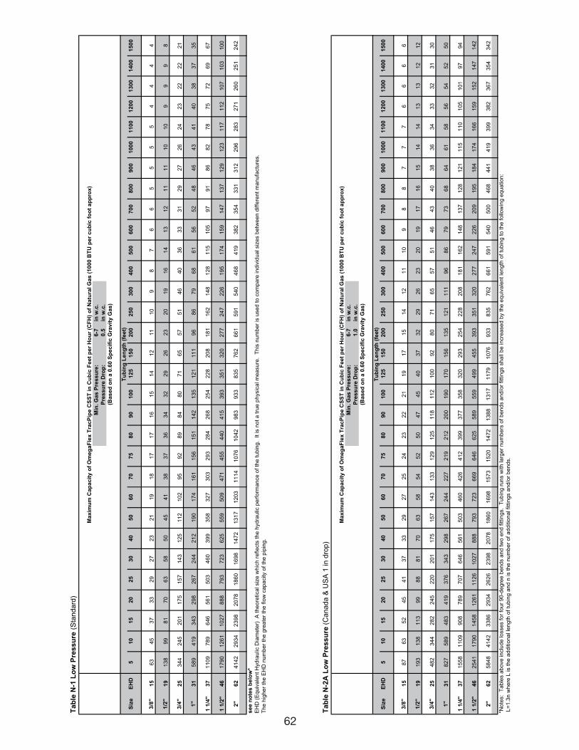
62
Ta
ble
N-1
Lo
w P
res
su
re (
Sta
nd
ard
)
Min
. G
as
Pre
ss
ure
:6
-7in
w.c
.
Pre
ss
ure
Dro
p:
0.5
in w
.c.
Siz
eE
HD
51
01
52
02
53
04
05
06
07
07
58
09
01
00
12
51
50
20
02
50
30
04
00
50
06
00
70
08
00
90
01
00
01
10
01
20
01
30
01
40
01
50
0
3/8
"
15
63
45
37
33
29
27
23
21
19
18
17
17
16
15
14
12
11
10
98
76
65
55
54
44
4
1/2
"
19
13
89
98
17
06
35
85
04
54
13
83
73
63
43
22
92
62
32
01
91
61
41
31
21
11
11
01
09
99
8
3/4
"
25
34
42
45
20
11
75
15
71
43
12
51
12
10
29
59
28
98
48
07
16
55
75
14
64
03
63
33
12
92
72
62
42
32
22
22
1
1"
31
58
94
19
34
32
98
26
72
44
21
21
90
17
41
61
15
61
51
14
21
35
12
11
11
96
86
79
68
61
56
52
48
46
43
41
40
38
37
35
1 1
/4"
37
11
09
78
96
46
56
15
03
46
03
99
35
83
27
30
32
93
28
42
68
25
42
28
20
81
81
16
21
48
12
81
15
10
59
79
18
68
27
87
57
26
96
7
1 1
/2"
46
17
90
12
61
10
27
88
87
93
72
36
25
55
95
09
47
14
55
44
04
15
39
33
51
32
02
77
24
72
26
19
51
74
15
91
47
13
71
29
12
31
17
11
21
07
10
31
00
2"
62
41
42
29
34
23
98
20
78
18
60
16
98
14
72
13
17
12
03
11
14
10
76
10
42
98
39
33
83
57
62
66
15
91
54
04
68
41
93
82
35
43
31
31
22
96
28
32
71
26
02
51
24
2
se
e n
ote
s b
elo
w*
EH
D (
Eq
uiv
ale
nt
Hyd
rau
lic D
iam
ete
r)
A t
he
ore
tica
l siz
e w
hic
h r
efle
cts
th
e h
yd
rau
lic p
erf
orm
an
ce
of
the
tu
bin
g.
It
is n
ot
a t
rue
ph
ysic
al m
ea
su
re.
Th
is n
um
be
r is
use
d t
o c
om
pa
re in
div
idu
al siz
es b
etw
ee
n d
iffe
ren
t m
an
ufa
ctu
res.
Th
e h
igh
er
the
EH
D n
um
be
r th
e g
rea
ter
the
flo
w c
ap
acity o
f th
e p
ipin
g.
Ta
ble
N-2
A L
ow
Pre
ss
ure
(C
anada &
US
A 1
in d
rop)
Min
. G
as
Pre
ss
ure
:6
-7in
w.c
.
Pre
ss
ure
Dro
p:
1.0
in w
.c.
Siz
eE
HD
51
01
52
02
53
04
05
06
07
07
58
09
01
00
12
51
50
20
02
50
30
04
00
50
06
00
70
08
00
90
01
00
01
10
01
20
01
30
01
40
01
50
0
3/8
"
15
87
63
52
45
41
37
33
29
27
25
24
23
22
21
19
17
15
14
12
11
10
98
87
77
66
66
1/2
"
19
19
31
38
11
39
98
88
17
06
35
85
45
25
04
74
54
03
73
22
92
62
32
01
91
71
61
51
41
41
31
31
21
2
3/4
"
25
48
23
44
28
22
45
22
02
01
17
51
57
14
31
33
12
91
25
11
81
12
10
09
28
07
16
55
75
14
64
34
03
83
63
43
33
23
13
0
1"
31
82
75
89
48
34
19
37
63
43
29
82
67
24
42
27
21
92
12
20
01
90
17
01
56
13
51
21
11
19
68
67
97
36
86
46
15
85
65
45
25
0
1 1
/4"
37
15
58
11
09
90
87
89
70
76
46
56
15
03
46
04
26
41
23
99
37
73
58
32
02
93
25
42
28
20
81
81
16
21
48
13
71
28
12
11
15
11
01
05
10
19
79
4
1 1
/2"
46
25
41
17
90
14
58
12
61
11
26
10
27
88
87
93
72
36
69
64
66
25
58
95
59
49
94
55
39
33
51
32
02
77
24
72
26
20
91
95
18
41
74
16
61
59
15
21
47
14
2
2"
62
58
48
41
42
33
86
29
34
26
26
23
98
20
78
18
60
16
98
15
73
15
20
14
72
13
88
13
17
11
79
10
76
93
38
35
76
26
61
59
15
40
50
04
68
44
14
19
39
93
82
36
73
54
34
2
*No
tes:
Ta
ble
s a
bo
ve
in
clu
de
lo
sse
s f
or
fou
r 9
0-d
eg
ree
be
nd
s a
nd
tw
o e
nd
fittin
gs.
Tu
bin
g r
un
s w
ith
la
rge
r n
um
be
rs o
f b
en
ds a
nd
/or
fitt
ing
s s
ha
ll b
e in
cre
ase
d b
y t
he
eq
uiv
ale
nt
len
gth
of
tub
ing
to
th
e f
ollo
win
g e
qu
atio
n:
L=
1.3
n w
he
re L
is t
he
ad
ditio
na
l le
ng
th o
f tu
bin
g a
nd
n is t
he
nu
mb
er
of
ad
ditio
na
l fitt
ing
s a
nd
/or
be
nd
s.
Ma
xim
um
Ca
pa
cit
y o
f O
me
ga
Fle
x T
rac
Pip
e C
SS
T i
n C
ub
ic F
ee
t p
er
Ho
ur
(CF
H)
of
Na
tura
l G
as
(1
00
0 B
TU
pe
r c
ub
ic f
oo
t a
pp
rox
)
(Ba
se
d o
n a
0.6
0 S
pe
cif
ic G
rav
ity
Ga
s)
Tu
bin
g L
en
gth
(fe
et)
Ma
xim
um
Ca
pa
cit
y o
f O
me
ga
Fle
x T
rac
Pip
e C
SS
T i
n C
ub
ic F
ee
t p
er
Ho
ur
(CF
H)
of
Na
tura
l G
as
(1
00
0 B
TU
pe
r c
ub
ic f
oo
t a
pp
rox
)
(Ba
se
d o
n a
0.6
0 S
pe
cif
ic G
rav
ity
Ga
s)
Tu
bin
g L
en
gth
(fe
et)
111743_OmegaFlex_Txt:111743_OmegaFlex_Txt 5/28/09 11:57 AM Page 62
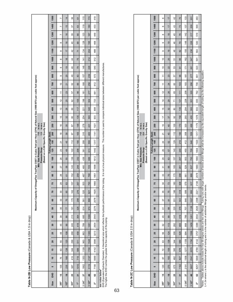
63
Ta
ble
N-2
B L
ow
Pre
ss
ure
(C
anada &
US
A 1
.5 in d
rop)
Min
. G
as
Pre
ss
ure
:7
-8in
w.c
.
Pre
ss
ure
Dro
p:
1.5
in w
.c.
Siz
eE
HD
51
01
52
02
53
04
05
06
07
07
58
09
01
00
12
51
50
20
02
50
30
04
00
50
06
00
70
08
00
90
01
00
01
10
01
20
01
30
01
40
01
50
0
3/8
"1
51
05
76
63
55
49
45
39
35
33
30
29
28
27
26
23
21
18
16
15
13
12
11
10
99
88
87
77
1/2
"1
92
35
16
81
38
12
01
08
99
86
77
70
65
63
61
58
55
49
45
39
35
32
28
25
23
21
20
19
18
17
16
16
15
14
3/4
"
25
58
74
19
34
42
99
26
82
45
21
31
91
17
51
62
15
71
52
14
31
36
12
21
12
97
87
80
69
62
57
52
49
46
44
42
40
39
37
36
1"
31
10
10
71
95
89
51
14
58
41
93
64
32
62
98
27
62
67
25
92
44
23
22
08
19
01
65
14
81
35
11
71
05
96
89
83
79
75
71
68
66
63
61
1 1
/4"
37
19
02
13
53
11
09
96
38
63
78
96
85
61
45
61
52
05
03
48
74
60
43
63
91
35
83
10
27
82
54
22
11
98
18
11
68
15
71
48
14
11
34
12
81
23
11
91
15
1 1
/2"
46
31
19
21
97
17
90
15
48
13
83
12
61
10
90
97
48
88
82
17
93
76
87
23
68
66
13
55
94
83
43
13
93
34
03
04
27
72
56
23
92
26
21
42
04
19
51
87
18
01
74
2"
62
71
56
50
69
41
42
35
90
32
13
29
34
25
43
22
76
20
78
19
25
18
60
18
01
16
98
16
12
14
42
13
17
11
41
10
21
93
38
08
72
36
61
61
25
72
54
05
12
48
84
68
44
94
33
41
9
se
e n
ote
s b
elo
w*
EH
D (
Eq
uiv
ale
nt
Hyd
rau
lic D
iam
ete
r)
A t
he
ore
tica
l siz
e w
hic
h r
efle
cts
th
e h
yd
rau
lic p
erf
orm
an
ce
of
the
tu
bin
g.
It
is n
ot
a t
rue
ph
ysic
al m
ea
su
re.
Th
is n
um
be
r is
use
d t
o c
om
pa
re in
div
idu
al siz
es b
etw
ee
n d
iffe
ren
t m
an
ufa
ctu
res.
Th
e h
igh
er
the
EH
D n
um
be
r th
e g
rea
ter
the
flo
w c
ap
acity o
f th
e p
ipin
g.
(Ba
se
d o
n a
0.6
0 S
pe
cif
ic G
rav
ity
Ga
s)
Tu
bin
g L
en
gth
(fe
et)
Ma
xim
um
Ca
pa
cit
y o
f O
me
ga
Fle
x T
rac
Pip
e C
SS
T i
n C
ub
ic F
ee
t p
er
Ho
ur
(CF
H)
of
Na
tura
l G
as
(1
00
0 B
TU
pe
r c
ub
ic f
oo
t a
pp
rox
)
Ta
ble
N-2
C L
ow
Pre
ss
ure
(C
anada &
US
A 2
.0 in d
rop)
Min
. G
as
Pre
ss
ure
:7
-8in
w.c
.
Pre
ss
ure
Dro
p:
2.0
in w
.c.
Siz
eE
HD
51
01
52
02
53
04
05
06
07
07
58
09
01
00
12
51
50
20
02
50
30
04
00
50
06
00
70
08
00
90
01
00
01
10
01
20
01
30
01
40
01
50
0
3/8
"
15
12
08
77
26
35
65
24
54
13
73
53
43
33
12
92
62
42
11
91
71
51
41
21
11
11
01
09
98
88
1/2
"
19
27
01
93
15
91
38
12
41
13
99
88
81
75
73
70
66
63
57
52
45
40
37
32
29
26
24
23
22
20
19
19
18
17
17
3/4
"
25
67
54
82
39
53
44
30
82
82
24
52
20
20
11
86
18
01
75
16
51
57
14
01
29
11
21
00
92
80
71
65
60
57
53
51
48
46
45
43
42
1"
31
11
62
82
76
78
58
95
28
48
34
19
37
63
43
31
83
08
29
82
81
26
72
40
21
91
90
17
01
56
13
51
21
11
11
03
96
91
86
82
79
76
73
70
1 1
/4"
37
21
91
15
58
12
77
11
09
99
49
08
78
97
07
64
65
99
57
95
61
52
95
03
45
04
12
35
83
20
29
32
54
22
82
08
19
31
81
17
11
62
15
51
48
14
21
37
13
3
1 1
/2"
46
36
07
25
41
20
70
17
90
15
99
14
58
12
61
11
26
10
27
95
09
17
88
88
37
79
37
09
64
65
59
49
94
55
39
33
51
32
02
96
27
72
61
24
72
36
22
62
17
20
92
01
2"
62
82
57
58
48
47
80
41
42
37
07
33
86
29
34
26
26
23
98
22
21
21
46
20
78
19
60
18
60
16
64
15
20
13
17
11
79
10
76
93
38
35
76
27
06
66
16
23
59
15
64
54
05
19
50
04
83
*No
tes:
Ta
ble
s a
bo
ve
in
clu
de
lo
sse
s f
or
fou
r 9
0-d
eg
ree
be
nd
s a
nd
tw
o e
nd
fittin
gs.
Tu
bin
g r
un
s w
ith
la
rge
r n
um
be
rs o
f b
en
ds a
nd
/or
fitt
ing
s s
ha
ll b
e in
cre
ase
d b
y t
he
eq
uiv
ale
nt
len
gth
of
tub
ing
to
th
e f
ollo
win
g e
qu
atio
n:
L=
1.3
n w
he
re L
is t
he
ad
ditio
na
l le
ng
th o
f tu
bin
g a
nd
n is t
he
nu
mb
er
of
ad
ditio
na
l fitt
ing
s a
nd
/or
be
nd
s.
Tu
bin
g L
en
gth
(fe
et)
Ma
xim
um
Ca
pa
cit
y o
f O
me
ga
Fle
x T
rac
Pip
e C
SS
T i
n C
ub
ic F
ee
t p
er
Ho
ur
(CF
H)
of
Na
tura
l G
as
(1
00
0 B
TU
pe
r c
ub
ic f
oo
t a
pp
rox
)
(Ba
se
d o
n a
0.6
0 S
pe
cif
ic G
rav
ity
Ga
s)
111743_OmegaFlex_Txt:111743_OmegaFlex_Txt 5/28/09 11:57 AM Page 63
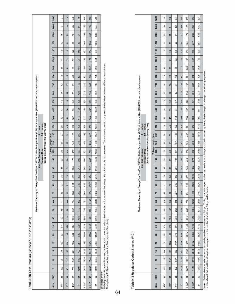
64
Ta
ble
N-2
D L
ow
Pre
ss
ure
(C
anada &
US
A 2
.5 in d
rop)
Min
. G
as
Pre
ss
ure
:8
in w
.c.
Pre
ss
ure
Dro
p:
2.5
in w
.c.
Siz
eE
HD
51
01
52
02
53
04
05
06
07
07
58
09
01
00
12
51
50
20
02
50
30
04
00
50
06
00
70
08
00
90
01
00
01
10
01
20
01
30
01
40
01
50
0
3/8
"
15
13
39
67
96
96
35
75
04
54
13
83
73
63
43
32
92
72
32
11
91
71
51
41
31
21
11
11
01
09
99
1/2
"1
93
01
21
51
77
15
41
38
12
61
10
99
90
84
81
78
74
70
63
58
50
45
41
36
32
29
27
25
24
23
22
21
20
19
19
3/4
"
25
75
35
37
44
13
83
34
43
14
27
32
45
22
42
08
20
11
95
18
41
75
15
71
43
12
51
12
10
28
98
07
36
76
36
05
75
45
25
04
84
6
1"
31
12
97
92
37
57
65
75
89
53
94
68
41
93
83
35
53
43
33
33
14
29
82
67
24
42
12
19
01
74
15
11
35
12
41
15
10
71
01
96
92
88
84
81
79
1 1
/4"
37
24
44
17
39
14
25
12
37
11
09
10
14
88
07
89
72
16
68
64
66
26
59
15
61
50
34
60
39
93
58
32
72
84
25
42
32
21
52
02
19
01
81
17
21
65
15
91
53
14
8
1 1
/2"
46
40
38
28
44
23
17
20
04
17
90
16
32
14
11
12
61
11
50
10
64
10
27
99
49
37
88
87
93
72
36
25
55
95
09
44
03
93
35
93
32
31
02
92
27
72
64
25
32
43
23
42
26
2"
62
92
27
65
35
53
41
46
29
41
42
37
83
32
79
29
34
26
80
24
82
23
98
23
22
21
90
20
78
18
60
16
98
14
72
13
17
12
03
10
42
93
38
52
78
97
38
69
66
61
63
06
03
58
05
59
54
0
se
e n
ote
s b
elo
w*
EH
D (
Eq
uiv
ale
nt
Hyd
rau
lic D
iam
ete
r)
A t
he
ore
tica
l siz
e w
hic
h r
efle
cts
th
e h
yd
rau
lic p
erf
orm
an
ce
of
the
tu
bin
g.
It
is n
ot
a t
rue
ph
ysic
al m
ea
su
re.
Th
is n
um
be
r is
use
d t
o c
om
pa
re in
div
idu
al siz
es b
etw
ee
n d
iffe
ren
t m
an
ufa
ctu
res.
Th
e h
igh
er
the
EH
D n
um
be
r th
e g
rea
ter
the
flo
w c
ap
acity o
f th
e p
ipin
g.
Ma
xim
um
Ca
pa
cit
y o
f O
me
ga
Fle
x T
rac
Pip
e C
SS
T i
n C
ub
ic F
ee
t p
er
Ho
ur
(CF
H)
of
Na
tura
l G
as
(1
00
0 B
TU
pe
r c
ub
ic f
oo
t a
pp
rox
)
Tu
bin
g L
en
gth
(fe
et)
(Ba
se
d o
n a
0.6
0 S
pe
cif
ic G
rav
ity
Ga
s)
Ta
ble
N-3
Re
gu
lato
r O
utl
et
(8 in
ch
es W
.C.)
Min
. G
as
Pre
ss
ure
:8
in w
.c.
Pre
ss
ure
Dro
p:
3.0
in w
.c.
Siz
eE
HD
51
01
52
02
53
04
05
06
07
07
58
09
01
00
12
51
50
20
02
50
30
04
00
50
06
00
70
08
00
90
01
00
01
10
01
20
01
30
01
40
01
50
0
3/8
"
15
16
01
12
90
78
69
63
55
49
45
42
41
39
37
35
32
29
26
23
21
18
16
15
14
13
12
12
11
11
10
10
10
1/2
"
19
32
92
35
19
31
68
15
11
38
12
01
08
99
91
88
86
81
77
69
63
55
49
45
39
35
32
30
28
26
25
24
23
22
21
20
3/4
"
25
82
35
87
48
24
19
37
53
44
29
92
68
24
52
27
22
02
13
20
11
91
17
11
57
13
61
22
11
29
78
78
07
46
96
56
25
95
75
45
25
1
1"
31
14
18
10
10
82
77
19
64
45
89
51
14
58
41
93
89
37
63
64
34
33
26
29
22
67
23
22
08
19
01
65
14
81
35
12
51
17
11
11
05
10
09
69
28
98
6
1 1
/4"
37
26
73
19
02
15
58
13
53
12
13
11
09
96
38
63
78
97
31
70
76
85
64
66
14
55
05
03
43
63
91
35
83
10
27
82
54
23
62
21
20
81
98
18
91
81
17
41
68
16
2
1 1
/2"
46
44
28
31
19
25
41
21
97
19
63
17
90
15
48
13
83
12
61
11
66
11
26
10
90
10
27
97
48
70
79
36
86
61
35
59
48
34
31
39
33
64
34
03
20
30
42
89
27
72
66
25
62
47
2"
62
10
10
37
15
65
84
85
06
94
53
64
14
23
59
03
21
32
93
42
71
72
62
62
54
32
39
82
27
62
03
61
86
01
61
21
44
21
31
71
14
11
02
19
33
86
48
08
76
27
23
69
06
61
63
56
12
59
1
*No
tes:
Ta
ble
s a
bo
ve
in
clu
de
lo
sse
s f
or
fou
r 9
0-d
eg
ree
be
nd
s a
nd
tw
o e
nd
fittin
gs.
Tu
bin
g r
un
s w
ith
la
rge
r n
um
be
rs o
f b
en
ds a
nd
/or
fitt
ing
s s
ha
ll b
e in
cre
ase
d b
y t
he
eq
uiv
ale
nt
len
gth
of
tub
ing
to
th
e f
ollo
win
g e
qu
atio
n:
L=
1.3
n w
he
re L
is t
he
ad
ditio
na
l le
ng
th o
f tu
bin
g a
nd
n is t
he
nu
mb
er
of
ad
ditio
na
l fitt
ing
s a
nd
/or
be
nd
s.
(Ba
se
d o
n a
0.6
0 S
pe
cif
ic G
rav
ity
Ga
s)
Tu
bin
g L
en
gth
(fe
et)
Ma
xim
um
Ca
pa
cit
y o
f O
me
ga
Fle
x T
rac
Pip
e C
SS
T i
n C
ub
ic F
ee
t p
er
Ho
ur
(CF
H)
of
Na
tura
l G
as
(1
00
0 B
TU
pe
r c
ub
ic f
oo
t a
pp
rox
)
111743_OmegaFlex_Txt:111743_OmegaFlex_Txt 5/28/09 11:57 AM Page 64
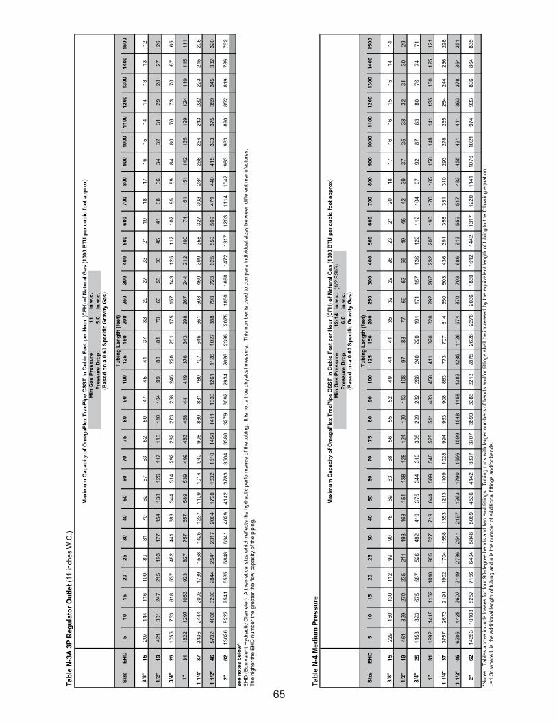
65
Ta
ble
N-3
A 3
P R
eg
ula
tor
Ou
tlet
(11
in
ch
es W
.C.)
Min
Ga
s P
res
su
re:
11
in w
.c.
Pre
ss
ure
Dro
p:
5.0
in w
.c.
Siz
eE
HD
51
01
52
02
53
04
05
06
07
07
58
09
01
00
12
51
50
20
02
50
30
04
00
50
06
00
70
08
00
90
01
00
01
10
01
20
01
30
01
40
01
50
0
3/8
"
15
20
71
44
11
61
00
89
81
70
62
57
53
52
50
47
45
41
37
33
29
27
23
21
19
18
17
16
15
14
14
13
13
12
1/2
"
19
42
13
01
24
72
15
19
31
77
15
41
38
12
61
17
11
31
10
10
49
98
88
17
06
35
85
04
54
13
83
63
43
23
12
92
82
72
6
3/4
"
25
10
55
75
36
18
53
74
82
44
13
83
34
43
14
29
22
82
27
32
58
24
52
20
20
11
75
15
71
43
12
51
12
10
29
58
98
48
07
67
37
06
76
5
1"
31
18
22
12
97
10
63
92
38
27
75
76
57
58
95
39
49
94
83
46
84
41
41
93
76
34
32
98
26
72
44
21
21
90
17
41
61
15
11
42
13
51
29
12
41
19
11
51
11
1 1
/4"
37
34
36
24
44
20
03
17
39
15
58
14
25
12
37
11
09
10
14
94
09
08
88
08
31
78
97
07
64
65
61
50
34
60
39
93
58
32
73
03
28
42
68
25
42
43
23
22
23
21
52
08
1 1
/2"
46
57
32
40
38
32
90
28
44
25
41
23
17
20
04
17
90
16
32
15
10
14
58
14
11
13
30
12
61
11
26
10
27
88
87
93
72
36
25
55
95
09
47
14
40
41
53
93
37
53
59
34
53
32
32
0
2"
62
13
02
69
22
77
54
16
53
55
84
85
34
14
62
94
14
23
78
33
50
43
38
63
27
93
09
22
93
42
62
62
39
82
07
81
86
01
69
81
47
21
31
71
20
31
11
41
04
29
83
93
38
90
85
28
19
78
97
62
se
e n
ote
s b
elo
w*
EH
D (
Eq
uiv
ale
nt
Hyd
rau
lic D
iam
ete
r)
A t
he
ore
tica
l siz
e w
hic
h r
efle
cts
th
e h
yd
rau
lic p
erf
orm
an
ce
of
the
tu
bin
g.
It
is n
ot
a t
rue
ph
ysic
al m
ea
su
re.
Th
is n
um
be
r is
use
d t
o c
om
pa
re in
div
idu
al siz
es b
etw
ee
n d
iffe
ren
t m
an
ufa
ctu
res.
Th
e h
igh
er
the
EH
D n
um
be
r th
e g
rea
ter
the
flo
w c
ap
acity o
f th
e p
ipin
g.
Ma
xim
um
Ca
pa
cit
y o
f O
me
ga
Fle
x T
rac
Pip
e C
SS
T i
n C
ub
ic F
ee
t p
er
Ho
ur
(CF
H)
of
Na
tura
l G
as
(1
00
0 B
TU
pe
r c
ub
ic f
oo
t a
pp
rox
)
(Ba
se
d o
n a
0.6
0 S
pe
cif
ic G
rav
ity
Ga
s)
Tu
bin
g L
en
gth
(fe
et)
Ta
ble
N-4
Me
diu
m P
res
su
re
Min
Ga
s P
res
su
re:
12
-14
in w
.c.
(1/2
PS
IG)
Pre
ss
ure
Dro
p:
6.0
in w
.c.
Siz
eE
HD
51
01
52
02
53
04
05
06
07
07
58
09
01
00
12
51
50
20
02
50
30
04
00
50
06
00
70
08
00
90
01
00
01
10
01
20
01
30
01
40
01
50
0
3/8
"
15
22
91
60
13
01
12
99
90
78
69
63
58
56
55
52
49
44
41
35
32
29
26
23
21
20
18
17
16
16
15
15
14
14
1/2
"
19
46
13
29
27
02
35
21
11
93
16
81
51
13
81
28
12
41
20
11
31
08
97
88
77
69
63
55
49
45
42
39
37
35
33
32
31
30
29
3/4
"
25
11
53
82
36
75
58
75
26
48
24
19
37
53
44
31
93
08
29
92
82
26
82
40
22
01
91
17
11
57
13
61
22
11
21
04
97
92
87
83
80
76
74
71
1"
31
19
92
14
18
11
62
10
10
90
58
27
71
96
44
58
95
46
52
85
11
48
34
58
41
13
76
32
62
92
26
72
32
20
81
90
17
61
65
15
61
48
14
11
35
13
01
25
12
1
1 1
/4"
37
37
57
26
73
21
91
19
02
17
04
15
58
13
53
12
13
11
09
10
28
99
49
63
90
88
63
77
37
07
61
45
50
50
34
36
39
13
58
33
13
10
29
32
78
26
52
54
24
42
36
22
8
1 1
/2"
46
62
86
44
28
36
07
31
19
27
86
25
41
21
97
19
63
17
90
16
56
15
99
15
48
14
58
13
83
12
35
11
26
97
48
70
79
36
86
61
35
59
51
74
83
45
54
31
41
13
93
37
83
64
35
1
2"
62
14
26
31
01
03
82
57
71
56
64
04
58
48
50
69
45
36
41
42
38
37
37
07
35
90
33
86
32
13
28
75
26
26
22
76
20
36
18
60
16
12
14
42
13
17
12
20
11
41
10
76
10
21
97
49
33
89
68
64
83
5
*No
tes:
Ta
ble
s a
bo
ve
in
clu
de
lo
sse
s f
or
fou
r 9
0-d
eg
ree
be
nd
s a
nd
tw
o e
nd
fittin
gs.
Tu
bin
g r
un
s w
ith
la
rge
r n
um
be
rs o
f b
en
ds a
nd
/or
fitt
ing
s s
ha
ll b
e in
cre
ase
d b
y t
he
eq
uiv
ale
nt
len
gth
of
tub
ing
to
th
e f
ollo
win
g e
qu
atio
n:
L=
1.3
n w
he
re L
is t
he
ad
ditio
na
l le
ng
th o
f tu
bin
g a
nd
n is t
he
nu
mb
er
of
ad
ditio
na
l fitt
ing
s a
nd
/or
be
nd
s.
(Ba
se
d o
n a
0.6
0 S
pe
cif
ic G
rav
ity
Ga
s)
Ma
xim
um
Ca
pa
cit
y o
f O
me
ga
Fle
x T
rac
Pip
e C
SS
T i
n C
ub
ic F
ee
t p
er
Ho
ur
(CF
H)
of
Na
tura
l G
as
(1
00
0 B
TU
pe
r c
ub
ic f
oo
t a
pp
rox
)
Tu
bin
g L
en
gth
(fe
et)
111743_OmegaFlex_Txt:111743_OmegaFlex_Txt 5/28/09 11:57 AM Page 65
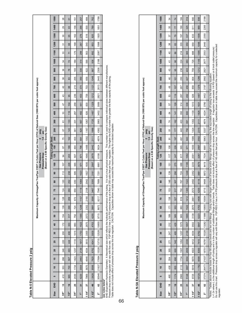
66
Ta
ble
N-5
Ele
va
ted
Pre
ss
ure
2 p
sig
Ga
s P
res
su
re:
2p
sig
Pre
ss
ure
Dro
p:
1.0
ps
i
Siz
eE
HD
51
01
52
02
53
04
05
06
07
07
58
09
01
00
12
51
50
20
02
50
30
04
00
50
06
00
70
08
00
90
01
00
01
10
01
20
01
30
01
40
01
50
0
3/8
"1
54
10
35
32
86
24
62
20
20
01
72
15
41
39
12
81
24
12
01
12
10
79
48
77
56
76
15
34
74
34
03
83
63
43
33
13
02
92
8
1/2
"
19
96
57
00
56
74
93
44
44
06
35
33
17
29
02
69
26
02
52
23
82
26
20
31
86
16
21
45
13
31
16
10
49
58
88
37
87
47
16
86
56
36
1
3/4
"
25
24
30
17
34
14
23
12
37
11
10
10
15
88
37
92
72
46
72
65
06
30
59
55
65
50
74
64
40
33
61
33
12
87
25
82
36
21
92
05
19
31
84
17
51
68
16
21
56
15
1
1"
31
42
20
30
04
24
63
21
39
19
17
17
53
15
22
13
65
12
48
11
57
11
18
10
84
10
23
97
18
71
79
66
91
62
05
67
49
24
41
40
33
74
35
03
30
31
42
99
28
72
76
26
62
57
1 1
/4"
37
79
69
56
70
46
46
40
34
36
15
33
05
28
70
25
72
23
52
21
80
21
08
20
42
19
27
18
30
16
40
14
99
13
02
11
67
10
67
92
68
30
75
97
03
65
96
22
59
05
63
54
05
19
50
04
84
1 1
/2"
46
13
62
69
59
97
82
06
76
26
04
15
50
94
76
34
25
53
88
13
59
03
46
73
35
53
16
12
99
72
67
82
44
22
11
11
88
61
72
01
48
71
32
91
21
21
12
11
04
89
87
93
68
92
85
38
20
78
97
62
2"
62
30
54
62
16
37
17
68
41
53
26
13
71
51
25
26
10
85
59
71
58
87
28
21
77
94
07
68
97
25
16
88
16
15
85
62
44
87
44
36
23
98
33
45
23
08
92
82
12
61
32
44
52
30
62
18
82
08
71
99
81
92
01
85
11
78
8
se
e n
ote
s b
elo
w*
EH
D (
Eq
uiv
ale
nt
Hyd
rau
lic D
iam
ete
r)
A t
he
ore
tica
l siz
e w
hic
h r
efle
cts
th
e h
yd
rau
lic p
erf
orm
an
ce
of
the
tu
bin
g.
It
is n
ot
a t
rue
ph
ysic
al m
ea
su
re.
Th
is n
um
be
r is
use
d t
o c
om
pa
re in
div
idu
al siz
es b
etw
ee
n d
iffe
ren
t m
an
ufa
ctu
res.
Pre
ssu
re d
rop
acro
ss a
re
gu
lato
r w
ill v
ary
with
flo
w r
ate
. F
GP
-RE
G-3
ha
s a
3/4
PS
I p
ressu
re d
rop
at
a f
low
of
25
0 c
ub
ic f
ee
t p
er
ho
ur.
re
gu
lato
r. T
he
hig
he
r th
e E
HD
nu
mb
er
the
gre
ate
r th
e f
low
ca
pa
city o
f th
e p
ipin
g.
Ta
ble
do
es n
ot
inclu
de
eff
ect
of
pre
ssu
re d
rop
acro
ss t
he
lin
e r
eg
ula
tor.
C
AU
TIO
N:
C
ap
acitie
s s
ho
wn
in
ta
ble
ma
y e
xce
ed
th
e m
axim
um
ca
pa
city f
or
a s
lecte
d r
eg
ula
tor.
Tu
bin
g L
en
gth
(fe
et)
(Ba
se
d o
n a
0.6
0 S
pe
cif
ic G
rav
ity
Ga
s)
Ma
xim
um
Ca
pa
cit
y o
f O
me
ga
Fle
x T
rac
Pip
e C
SS
T i
n C
ub
ic F
ee
t p
er
Ho
ur
(CF
H)
of
Na
tura
l G
as
(1
00
0 B
TU
pe
r c
ub
ic f
oo
t a
pp
rox
)
Ta
ble
N-5
A E
lev
ate
d P
res
su
re 2
ps
ig
Ga
s P
res
su
re:
2p
sig
Pre
ss
ure
Dro
p:
1.5
ps
i
Siz
eE
HD
51
01
52
02
53
04
05
06
07
07
58
09
01
00
12
51
50
20
02
50
30
04
00
50
06
00
70
08
00
90
01
00
01
10
01
20
01
30
01
40
01
50
0
3/8
"
15
49
54
38
35
43
05
27
12
47
21
21
89
17
11
58
15
31
48
13
91
31
11
71
06
91
81
74
64
57
53
49
46
43
41
40
38
37
35
34
1/2
"
19
11
74
85
56
90
60
05
42
49
54
29
38
53
53
32
73
17
30
72
90
27
52
47
22
61
97
17
71
62
14
11
26
11
61
07
10
19
59
08
68
37
97
77
4
3/4
"
25
29
60
21
12
17
34
15
07
13
52
12
37
10
75
96
58
83
81
97
92
76
77
24
68
86
17
56
54
91
44
04
03
35
03
14
28
72
67
25
02
36
22
42
14
20
51
97
19
01
84
1"
31
51
48
36
87
30
04
26
09
23
39
21
39
18
57
16
65
15
22
14
12
13
65
13
22
12
48
11
85
10
62
97
18
43
75
66
91
60
05
38
49
24
56
42
74
03
38
33
65
35
03
37
32
53
14
1 1
/4"
37
97
25
69
19
56
70
49
23
44
12
40
34
35
02
31
39
28
70
26
61
25
72
24
92
23
52
22
33
20
01
18
30
15
89
14
24
13
02
11
30
10
13
92
68
58
80
47
59
72
06
88
65
96
33
61
15
90
1 1
/2"
46
16
72
51
17
82
95
99
83
00
74
15
67
62
58
47
52
23
47
63
44
06
42
55
41
19
38
81
36
79
32
87
29
97
25
92
23
15
21
11
18
26
16
31
14
87
13
76
12
86
12
12
11
49
10
95
10
48
10
06
96
99
36
2"
62
37
37
42
64
73
21
63
71
87
51
16
78
11
53
26
13
28
21
18
86
10
85
51
00
54
97
15
94
08
88
72
84
19
75
34
68
81
59
63
53
37
48
74
42
24
37
80
34
52
31
97
29
92
28
21
26
77
25
53
24
45
23
50
22
65
21
88
*No
tes:
Ta
ble
s a
bo
ve
in
clu
de
lo
sse
s f
or
fou
r 9
0-d
eg
ree
be
nd
s a
nd
tw
o e
nd
fittin
gs.
Tu
bin
g r
un
s w
ith
la
rge
r n
um
be
rs o
f b
en
ds a
nd
/or
fitt
ing
s s
ha
ll b
e in
cre
ase
d b
y t
he
eq
uiv
ale
nt
len
gth
of
tub
ing
to
th
e f
ollo
win
g e
qu
atio
n:
L=
1.3
n w
he
re L
is t
he
ad
ditio
na
l le
ng
th o
f tu
bin
g a
nd
n is t
he
nu
mb
er
of
ad
ditio
na
l fitt
ing
s a
nd
/or
be
nd
s.
Ta
ble
do
es n
ot
inclu
de
eff
ect
of
pre
ssu
re d
rop
acro
ss t
he
lin
e r
eg
ula
tor.
I
f re
gu
lato
r lo
ss e
xce
ed
s 1
/4 P
SI
(ba
se
d o
n 8
in
ch
ou
tle
t p
ressu
re)
Do
no
t u
se
th
is c
ha
rt.
Pre
ssu
re d
rop
acro
ss a
re
gu
lato
r w
ill v
ary
with
flo
w r
ate
. F
GP
-RE
G-3
ha
s a
1/4
PS
I p
ressu
re d
rop
at
a f
low
of
14
5 c
ub
ic f
ee
t p
er
ho
ur.
C
AU
TIO
N:
C
ap
acitie
s s
ho
wn
in
ta
ble
ma
y e
xce
ed
th
e m
axim
um
ca
pa
city f
or
a s
ele
cte
d
reg
ula
tor.
Ma
xim
um
Ca
pa
cit
y o
f O
me
ga
Fle
x T
rac
Pip
e C
SS
T i
n C
ub
ic F
ee
t p
er
Ho
ur
(CF
H)
of
Na
tura
l G
as
(1
00
0 B
TU
pe
r c
ub
ic f
oo
t a
pp
rox
)
(Ba
se
d o
n a
0.6
0 S
pe
cif
ic G
rav
ity
Ga
s)
Tu
bin
g L
en
gth
(fe
et)
111743_OmegaFlex_Txt:111743_OmegaFlex_Txt 5/28/09 11:57 AM Page 66
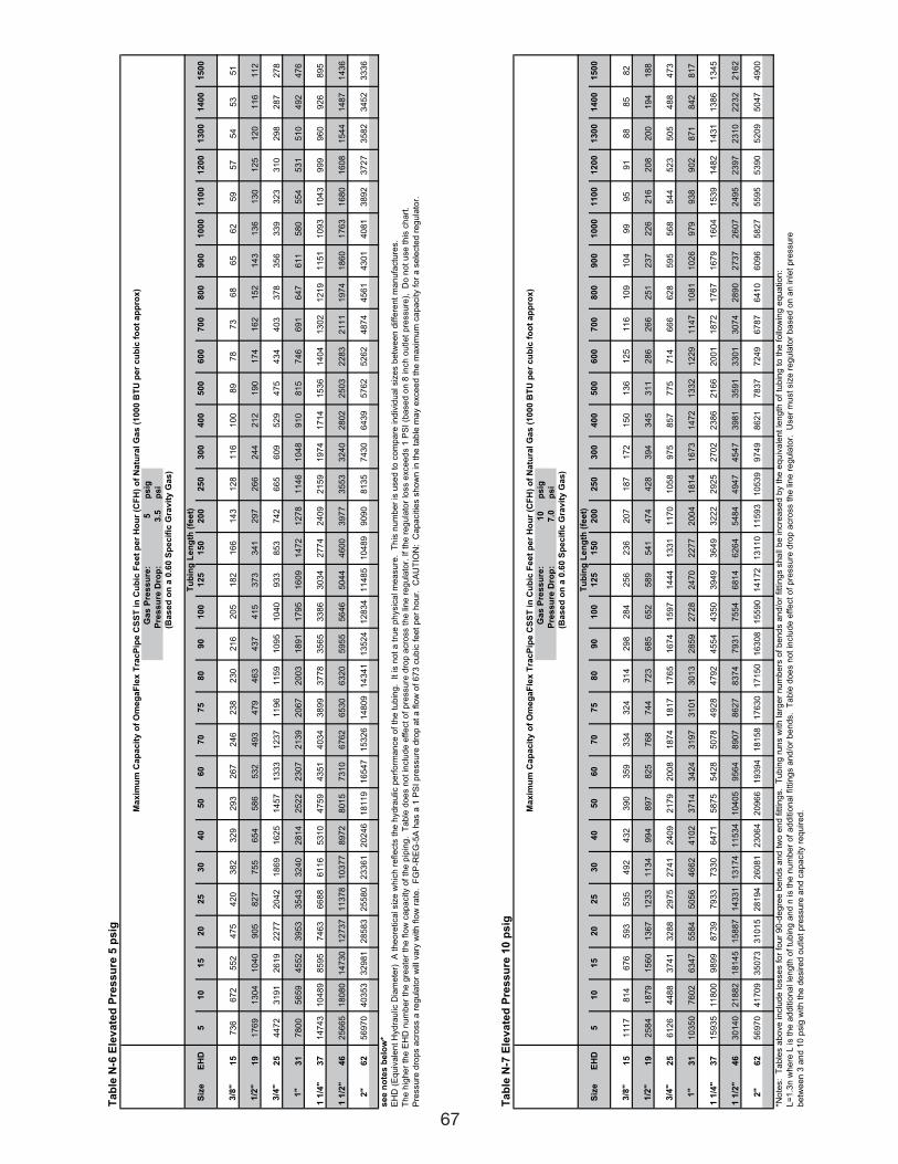
67
Ta
ble
N-6
Ele
va
ted
Pre
ss
ure
5 p
sig
Ga
s P
res
su
re:
5p
sig
Pre
ss
ure
Dro
p:
3.5
ps
i
Siz
eE
HD
51
01
52
02
53
04
05
06
07
07
58
09
01
00
12
51
50
20
02
50
30
04
00
50
06
00
70
08
00
90
01
00
01
10
01
20
01
30
01
40
01
50
0
3/8
"
15
73
66
72
55
24
75
42
03
82
32
92
93
26
72
46
23
82
30
21
62
05
18
21
66
14
31
28
11
61
00
89
78
73
68
65
62
59
57
54
53
51
1/2
"
19
17
69
13
04
10
40
90
58
27
75
56
54
58
65
32
49
34
79
46
34
37
41
53
73
34
12
97
26
62
44
21
21
90
17
41
62
15
21
43
13
61
30
12
51
20
11
61
12
3/4
"
25
44
72
31
91
26
19
22
77
20
42
18
69
16
25
14
57
13
33
12
37
11
96
11
59
10
95
10
40
93
38
53
74
26
65
60
95
29
47
54
34
40
33
78
35
63
39
32
33
10
29
82
87
27
8
1"
31
78
00
56
59
45
52
39
53
35
43
32
40
28
14
25
22
23
07
21
39
20
67
20
03
18
91
17
95
16
09
14
72
12
78
11
46
10
48
91
08
15
74
66
91
64
76
11
58
05
54
53
15
10
49
24
76
1 1
/4"
37
14
74
31
04
89
85
95
74
63
66
88
61
16
53
10
47
59
43
51
40
34
38
99
37
78
35
65
33
86
30
34
27
74
24
09
21
59
19
74
17
14
15
36
14
04
13
02
12
19
11
51
10
93
10
43
99
99
60
92
68
95
1 1
/2"
46
25
66
51
80
80
14
73
01
27
37
11
37
81
03
77
89
72
80
15
73
10
67
62
65
30
63
20
59
55
56
46
50
44
46
00
39
77
35
53
32
40
28
02
25
03
22
83
21
11
19
74
18
60
17
63
16
80
16
08
15
44
14
87
14
36
2"
62
56
97
04
03
53
32
98
12
85
83
25
58
02
33
61
20
24
61
81
19
16
54
71
53
26
14
80
91
43
41
13
52
41
28
34
11
48
51
04
89
90
90
81
35
74
30
64
39
57
62
52
62
48
74
45
61
43
01
40
81
38
92
37
27
35
82
34
52
33
36
se
e n
ote
s b
elo
w*
EH
D (
Eq
uiv
ale
nt
Hyd
rau
lic D
iam
ete
r)
A t
he
ore
tica
l siz
e w
hic
h r
efle
cts
th
e h
yd
rau
lic p
erf
orm
an
ce
of
the
tu
bin
g.
It
is n
ot
a t
rue
ph
ysic
al m
ea
su
re.
Th
is n
um
be
r is
use
d t
o c
om
pa
re in
div
idu
al siz
es b
etw
ee
n d
iffe
ren
t m
an
ufa
ctu
res.
Th
e h
igh
er
the
EH
D n
um
be
r th
e g
rea
ter
the
flo
w c
ap
acity o
f th
e p
ipin
g.
Ta
ble
do
es n
ot
inclu
de
eff
ect
of
pre
ssu
re d
rop
acro
ss t
he
lin
e r
eg
ula
tor.
If
the
re
gu
lato
r lo
ss e
xce
ed
s 1
PS
I (b
ase
d o
n 8
in
ch
ou
tle
t p
ressu
re),
D
o n
ot
use
th
is c
ha
rt.
Pre
ssu
re d
rop
s a
cro
ss a
re
gu
lato
r w
ill v
ary
with
flo
w r
ate
. F
GP
-RE
G-5
A h
as a
1 P
SI
pre
ssu
re d
rop
at
a f
low
of
67
3 c
ub
ic f
ee
t p
er
ho
ur.
C
AU
TIO
N:
Ca
pa
citie
s s
ho
wn
in
th
e t
ab
le m
ay e
xce
ed
th
e m
axim
um
ca
pa
city f
or
a s
ele
cte
d r
eg
ula
tor.
Ma
xim
um
Ca
pa
cit
y o
f O
me
ga
Fle
x T
rac
Pip
e C
SS
T i
n C
ub
ic F
ee
t p
er
Ho
ur
(CF
H)
of
Na
tura
l G
as
(1
00
0 B
TU
pe
r c
ub
ic f
oo
t a
pp
rox
)
(Ba
se
d o
n a
0.6
0 S
pe
cif
ic G
rav
ity
Ga
s)
Tu
bin
g L
en
gth
(fe
et)
Ta
ble
N-7
Ele
va
ted
Pre
ss
ure
10
ps
ig
Ga
s P
res
su
re:
10
ps
ig
Pre
ss
ure
Dro
p:
7.0
ps
i
Siz
eE
HD
51
01
52
02
53
04
05
06
07
07
58
09
01
00
12
51
50
20
02
50
30
04
00
50
06
00
70
08
00
90
01
00
01
10
01
20
01
30
01
40
01
50
0
3/8
"
15
11
17
81
46
76
59
35
35
49
24
32
39
03
59
33
43
24
31
42
98
28
42
56
23
62
07
18
71
72
15
01
36
12
51
16
10
91
04
99
95
91
88
85
82
1/2
"
19
25
84
18
79
15
60
13
67
12
33
11
34
99
48
97
82
57
68
74
47
23
68
56
52
58
95
41
47
44
28
39
43
45
31
12
86
26
62
51
23
72
26
21
62
08
20
01
94
18
8
3/4
"
25
61
26
44
88
37
41
32
88
29
75
27
41
24
09
21
79
20
08
18
74
18
17
17
65
16
74
15
97
14
44
13
31
11
70
10
58
97
58
57
77
57
14
66
66
28
59
55
68
54
45
23
50
54
88
47
3
1"
31
10
35
07
60
26
34
75
58
45
05
64
66
24
10
23
71
43
42
43
19
73
10
13
01
32
85
92
72
82
47
02
27
72
00
41
81
41
67
31
47
21
33
21
22
91
14
71
08
11
02
69
79
93
89
02
87
18
42
81
7
1 1
/4"
37
15
93
51
18
00
98
99
87
39
79
33
73
30
64
71
58
75
54
28
50
78
49
28
47
92
45
54
43
50
39
49
36
49
32
22
29
25
27
02
23
86
21
66
20
01
18
72
17
67
16
79
16
04
15
39
14
82
14
31
13
86
13
45
1 1
/2"
46
30
14
02
18
82
18
14
51
58
87
14
33
11
31
74
11
53
41
04
05
95
64
89
07
86
27
83
74
79
31
75
54
68
14
62
64
54
84
49
47
45
47
39
81
35
91
33
01
30
74
28
90
27
37
26
07
24
95
23
97
23
10
22
32
21
62
2"
62
56
97
04
17
09
35
07
33
10
15
28
19
42
60
81
23
06
42
09
66
19
39
41
81
58
17
63
01
71
50
16
30
81
55
90
14
17
21
31
10
11
59
31
05
39
97
49
86
21
78
37
72
49
67
87
64
10
60
96
58
27
55
95
53
90
52
09
50
47
49
00
*No
tes:
Ta
ble
s a
bo
ve
in
clu
de
lo
sse
s f
or
fou
r 9
0-d
eg
ree
be
nd
s a
nd
tw
o e
nd
fittin
gs.
Tu
bin
g r
un
s w
ith
la
rge
r n
um
be
rs o
f b
en
ds a
nd
/or
fitt
ing
s s
ha
ll b
e in
cre
ase
d b
y t
he
eq
uiv
ale
nt
len
gth
of
tub
ing
to
th
e f
ollo
win
g e
qu
atio
n:
L=
1.3
n w
he
re L
is t
he
ad
ditio
na
l le
ng
th o
f tu
bin
g a
nd
n is t
he
nu
mb
er
of
ad
ditio
na
l fitt
ing
s a
nd
/or
be
nd
s.
Ta
ble
do
es n
ot
inclu
de
eff
ect
of
pre
ssu
re d
rop
acro
ss t
he
lin
e r
eg
ula
tor.
U
se
r m
ust
siz
e r
eg
ula
tor
ba
se
d o
n a
n in
let
pre
ssu
re
be
twe
en
3 a
nd
10
psig
with
th
e d
esire
d o
utle
t p
ressu
re a
nd
ca
pa
city r
eq
uire
d.M
ax
imu
m C
ap
ac
ity
of
Om
eg
aF
lex
Tra
cP
ipe
CS
ST
in
Cu
bic
Fe
et
pe
r H
ou
r (C
FH
) o
f N
atu
ral
Ga
s (
10
00
BT
U p
er
cu
bic
fo
ot
ap
pro
x)
(Ba
se
d o
n a
0.6
0 S
pe
cif
ic G
rav
ity
Ga
s)
Tu
bin
g L
en
gth
(fe
et)
111743_OmegaFlex_Txt:111743_OmegaFlex_Txt 5/28/09 11:57 AM Page 67
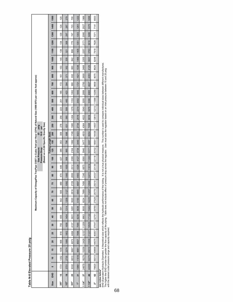
68
Ta
ble
N-8
Ele
va
ted
Pre
ss
ure
25
ps
ig
Ga
s P
res
su
re:
25
ps
ig
Pre
ss
ure
Dro
p:
10
.0p
si
Siz
eE
HD
51
01
52
02
53
04
05
06
07
07
58
09
01
00
12
51
50
20
02
50
30
04
00
50
06
00
70
08
00
90
01
00
01
10
01
20
01
30
01
40
01
50
0
3/8
"
15
17
31
12
52
10
36
90
68
16
75
06
55
59
15
42
50
54
89
47
44
49
42
73
85
35
33
09
27
82
56
22
32
01
18
51
72
16
11
53
14
51
39
13
41
29
12
41
20
1/2
"
19
37
51
27
35
22
74
19
95
18
02
16
58
14
54
13
14
12
09
11
27
10
92
10
60
10
05
95
88
65
79
66
98
63
15
80
50
94
60
42
33
94
37
13
52
33
53
21
30
82
97
28
72
79
3/4
"
25
93
32
68
13
56
67
49
73
44
94
41
37
36
31
32
81
30
20
28
16
27
29
26
50
25
12
23
95
21
64
19
92
17
48
15
80
14
54
12
76
11
53
10
62
99
09
32
88
38
42
80
67
75
74
77
23
70
0
1"
31
15
86
11
16
16
96
81
85
07
76
96
70
90
62
30
56
36
51
93
48
45
46
97
45
63
43
28
41
27
37
34
34
40
30
23
27
34
25
19
22
14
20
02
18
45
17
21
16
21
15
38
14
66
14
05
13
51
13
03
12
61
12
22
1 1
/4"
37
24
87
91
82
76
15
25
91
34
26
12
15
71
12
09
98
63
89
30
82
34
76
89
74
56
72
45
68
75
65
60
59
40
54
77
48
19
43
64
40
23
35
40
32
05
29
56
27
60
26
00
24
68
23
55
22
57
21
71
20
95
20
27
19
66
1 1
/2"
46
44
30
03
22
70
26
81
02
35
06
21
22
71
95
29
17
12
21
54
62
14
22
51
32
57
12
84
61
24
72
11
81
91
12
63
10
17
19
35
78
20
47
40
86
81
65
97
65
39
64
96
54
62
74
35
34
12
53
93
13
76
33
61
63
48
63
37
03
26
6
2"
62
79
82
05
93
13
49
85
64
40
75
40
05
73
70
47
32
75
12
97
65
27
52
92
57
70
25
01
92
43
37
23
13
92
21
18
20
10
21
85
91
16
43
61
49
37
13
81
51
22
13
11
09
91
02
66
96
09
90
75
86
29
82
48
79
18
76
28
73
71
71
41
69
33
se
e n
ote
s b
elo
w*
EH
D (
Eq
uiv
ale
nt
Hyd
rau
lic D
iam
ete
r)
A t
he
ore
tica
l siz
e w
hic
h r
efle
cts
th
e h
yd
rau
lic p
erf
orm
an
ce
of
the
tu
bin
g.
It
is n
ot
a t
rue
ph
ysic
al m
ea
su
re.
Th
is n
um
be
r is
use
d t
o c
om
pa
re in
div
idu
al siz
es b
etw
ee
n d
iffe
ren
t m
an
ufa
ctu
res.
Th
e h
igh
er
the
EH
D n
um
be
r th
e g
rea
ter
the
flo
w c
ap
acity o
f th
e p
ipin
g.
Ta
ble
do
es n
ot
inclu
de
eff
ect
of
pre
ssu
re d
rop
acro
ss t
he
re
gu
lato
r.
Use
r m
ust
siz
e t
he
re
gu
lato
r b
ase
d o
n a
n in
let
pre
ssu
re b
etw
ee
n 1
5 a
nd
25
psig
with
th
e d
esire
d o
utle
t p
ressu
re r
an
ge
an
d c
ap
acity r
eq
uire
d.
Ma
xim
um
Ca
pa
cit
y o
f O
me
ga
Fle
x T
rac
Pip
e C
SS
T i
n C
ub
ic F
ee
t p
er
Ho
ur
(CF
H)
of
Na
tura
l G
as
(1
00
0 B
TU
pe
r c
ub
ic f
oo
t a
pp
rox
)
(Ba
se
d o
n a
0.6
0 S
pe
cif
ic G
rav
ity
Ga
s)
Tu
bin
g L
en
gth
(fe
et)
111743_OmegaFlex_Txt:111743_OmegaFlex_Txt 5/28/09 11:57 AM Page 68
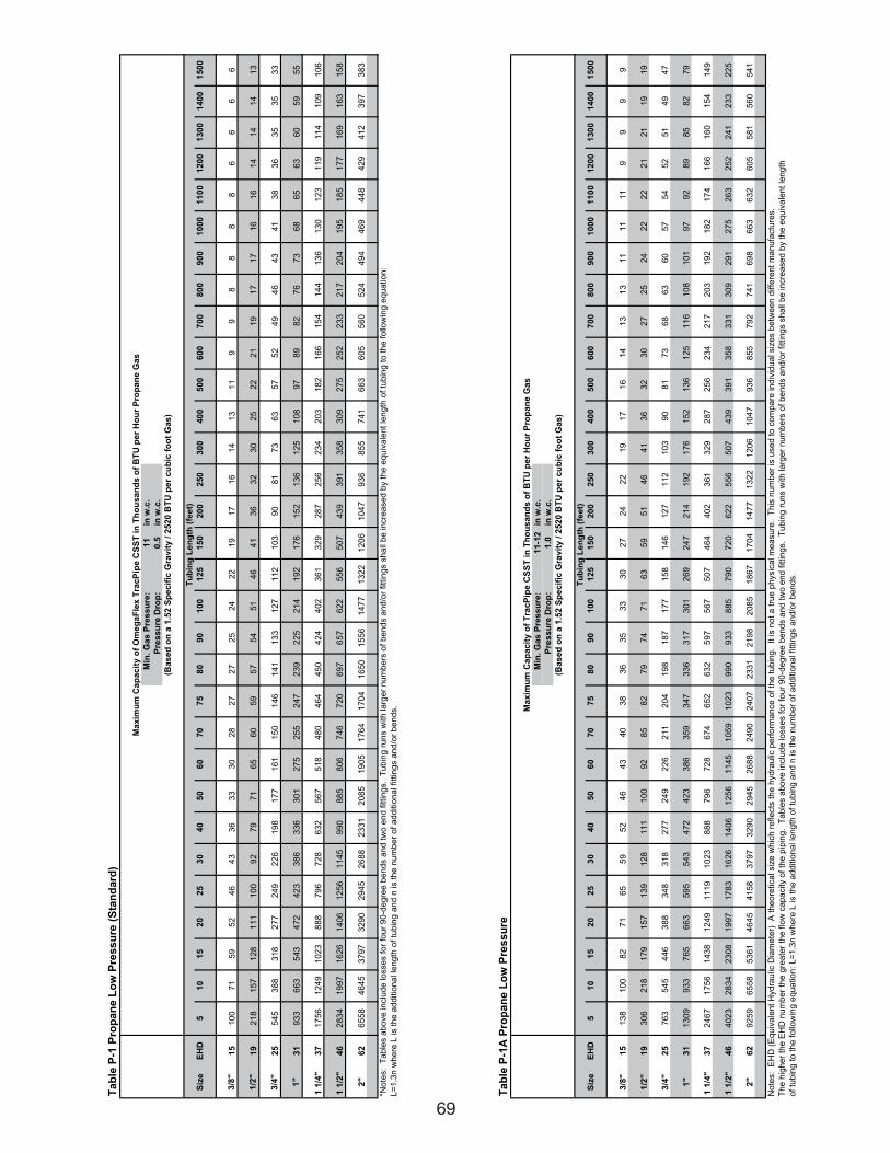
69
Ta
ble
P-1
Pro
pa
ne
Lo
w P
res
su
re (
Sta
nd
ard
)
Min
. G
as
Pre
ss
ure
:1
1in
w.c
.
Pre
ss
ure
Dro
p:
0.5
in w
.c.
Siz
eE
HD
51
01
52
02
53
04
05
06
07
07
58
09
01
00
12
51
50
20
02
50
30
04
00
50
06
00
70
08
00
90
01
00
01
10
01
20
01
30
01
40
01
50
0
3/8
"
15
10
07
15
95
24
64
33
63
33
02
82
72
72
52
42
21
91
71
61
41
31
19
98
88
86
66
6
1/2
"
19
21
81
57
12
81
11
10
09
27
97
16
56
05
95
75
45
14
64
13
63
23
02
52
22
11
91
71
71
61
61
41
41
41
3
3/4
"
25
54
53
88
31
82
77
24
92
26
19
81
77
16
11
50
14
61
41
13
31
27
11
21
03
90
81
73
63
57
52
49
46
43
41
38
36
35
35
33
1"
31
93
36
63
54
34
72
42
33
86
33
63
01
27
52
55
24
72
39
22
52
14
19
21
76
15
21
36
12
51
08
97
89
82
76
73
68
65
63
60
59
55
1 1
/4"
37
17
56
12
49
10
23
88
87
96
72
86
32
56
75
18
48
04
64
45
04
24
40
23
61
32
92
87
25
62
34
20
31
82
16
61
54
14
41
36
13
01
23
11
91
14
10
91
06
1 1
/2"
46
28
34
19
97
16
26
14
06
12
56
11
45
99
08
85
80
67
46
72
06
97
65
76
22
55
65
07
43
93
91
35
83
09
27
52
52
23
32
17
20
41
95
18
51
77
16
91
63
15
8
2"
62
65
58
46
45
37
97
32
90
29
45
26
88
23
31
20
85
19
05
17
64
17
04
16
50
15
56
14
77
13
22
12
06
10
47
93
68
55
74
16
63
60
55
60
52
44
94
46
94
48
42
94
12
39
73
83
*No
tes:
Ta
ble
s a
bo
ve
in
clu
de
lo
sse
s f
or
fou
r 9
0-d
eg
ree
be
nd
s a
nd
tw
o e
nd
fittin
gs.
Tu
bin
g r
un
s w
ith
la
rge
r n
um
be
rs o
f b
en
ds a
nd
/or
fitt
ing
s s
ha
ll b
e in
cre
ase
d b
y t
he
eq
uiv
ale
nt
len
gth
of
tub
ing
to
th
e f
ollo
win
g e
qu
atio
n:
L=
1.3
n w
he
re L
is t
he
ad
ditio
na
l le
ng
th o
f tu
bin
g a
nd
n is t
he
nu
mb
er
of
ad
ditio
na
l fitt
ing
s a
nd
/or
be
nd
s.
(Ba
se
d o
n a
1.5
2 S
pe
cif
ic G
rav
ity
/ 2
52
0 B
TU
pe
r c
ub
ic f
oo
t G
as
)
Ma
xim
um
Ca
pa
cit
y o
f O
me
ga
Fle
x T
rac
Pip
e C
SS
T i
n T
ho
us
an
ds
of
BT
U p
er
Ho
ur
Pro
pa
ne
Ga
s
Tu
bin
g L
en
gth
(fe
et)
Ta
ble
P-1
A P
rop
an
e L
ow
Pre
ss
ure
Min
. G
as
Pre
ss
ure
:1
1-1
2in
w.c
.
Pre
ss
ure
Dro
p:
1.0
in w
.c.
Siz
eE
HD
51
01
52
02
53
04
05
06
07
07
58
09
01
00
12
51
50
20
02
50
30
04
00
50
06
00
70
08
00
90
01
00
01
10
01
20
01
30
01
40
01
50
0
3/8
"
15
13
81
00
82
71
65
59
52
46
43
40
38
36
35
33
30
27
24
22
19
17
16
14
13
13
11
11
11
99
99
1/2
"
19
30
62
18
17
91
57
13
91
28
11
11
00
92
85
82
79
74
71
63
59
51
46
41
36
32
30
27
25
24
22
22
21
21
19
19
3/4
"
25
76
35
45
44
63
88
34
83
18
27
72
49
22
62
11
20
41
98
18
71
77
15
81
46
12
71
12
10
39
08
17
36
86
36
05
75
45
25
14
94
7
1"
31
13
09
93
37
65
66
35
95
54
34
72
42
33
86
35
93
47
33
63
17
30
12
69
24
72
14
19
21
76
15
21
36
12
51
16
10
81
01
97
92
89
85
82
79
1 1
/4"
37
24
67
17
56
14
38
12
49
11
19
10
23
88
87
96
72
86
74
65
26
32
59
75
67
50
74
64
40
23
61
32
92
87
25
62
34
21
72
03
19
21
82
17
41
66
16
01
54
14
9
1 1
/2"
46
40
23
28
34
23
08
19
97
17
83
16
26
14
06
12
56
11
45
10
59
10
23
99
09
33
88
57
90
72
06
22
55
65
07
43
93
91
35
83
31
30
92
91
27
52
63
25
22
41
23
32
25
2"
62
92
59
65
58
53
61
46
45
41
58
37
97
32
90
29
45
26
88
24
90
24
07
23
31
21
98
20
85
18
67
17
04
14
77
13
22
12
06
10
47
93
68
55
79
27
41
69
86
63
63
26
05
58
15
60
54
1
No
tes:
EH
D (
Eq
uiv
ale
nt
Hyd
rau
lic D
iam
ete
r)
A t
he
ore
tica
l siz
e w
hic
h r
efle
cts
th
e h
yd
rau
lic p
erf
orm
an
ce
of
the
tu
bin
g.
It
is n
ot
a t
rue
ph
ysic
al m
ea
su
re.
Th
is n
um
be
r is
use
d t
o c
om
pa
re in
div
idu
al siz
es b
etw
ee
n d
iffe
ren
t m
an
ufa
ctu
res.
Th
e h
igh
er
the
EH
D n
um
be
r th
e g
rea
ter
the
flo
w c
ap
acity o
f th
e p
ipin
g.
Ta
ble
s a
bo
ve
in
clu
de
lo
sse
s f
or
fou
r 9
0-d
eg
ree
be
nd
s a
nd
tw
o e
nd
fittin
gs.
Tu
bin
g r
un
s w
ith
la
rge
r n
um
be
rs o
f b
en
ds a
nd
/or
fitt
ing
s s
ha
ll b
e in
cre
ase
d b
y t
he
eq
uiv
ale
nt
len
gth
of
tub
ing
to
th
e f
ollo
win
g e
qu
atio
n:
L=
1.3
n w
he
re L
is t
he
ad
ditio
na
l le
ng
th o
f tu
bin
g a
nd
n is t
he
nu
mb
er
of
ad
ditio
na
l fitt
ing
s a
nd
/or
be
nd
s.
(Ba
se
d o
n a
1.5
2 S
pe
cif
ic G
rav
ity
/ 2
52
0 B
TU
pe
r c
ub
ic f
oo
t G
as
)
Tu
bin
g L
en
gth
(fe
et)
Ma
xim
um
Ca
pa
cit
y o
f T
rac
Pip
e C
SS
T i
n T
ho
us
an
ds
of
BT
U p
er
Ho
ur
Pro
pa
ne
Ga
s
111743_OmegaFlex_Txt:111743_OmegaFlex_Txt 5/28/09 11:57 AM Page 69
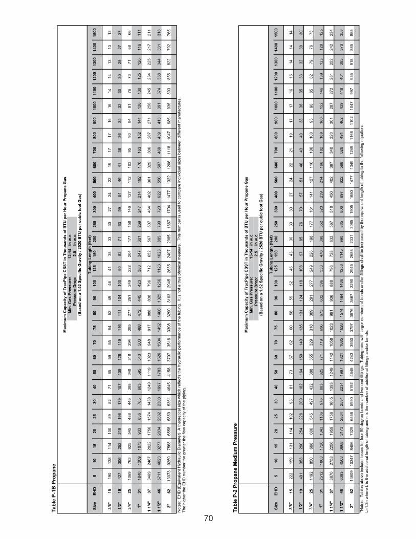
Ta
ble
P-2
Pro
pa
ne
Me
diu
m P
res
su
re
Min
. G
as
Pre
ss
ure
:1
3-1
4in
w.c
.
Pre
ss
ure
Dro
p:
2.5
in w
.c.
Siz
eE
HD
51
01
52
02
53
04
05
06
07
07
58
09
01
00
12
51
50
20
02
50
30
04
00
50
06
00
70
08
00
90
01
00
01
10
01
20
01
30
01
40
01
50
0
3/8
"
15
22
21
59
13
11
14
10
29
38
17
36
76
26
05
85
55
24
64
33
63
33
02
72
42
22
11
91
71
71
61
61
41
41
4
1/2
"
19
49
13
53
29
02
54
22
82
09
18
21
64
15
01
40
13
51
31
12
41
18
10
89
78
57
67
05
75
14
64
34
03
83
63
53
33
23
03
0
3/4
"
25
11
92
85
06
98
60
65
45
49
74
32
38
83
55
32
93
18
30
92
91
27
72
49
22
61
98
17
71
61
14
11
27
11
61
06
10
09
59
08
58
27
97
67
3
1"
31
25
12
18
63
17
20
13
43
11
06
97
68
83
82
57
71
71
96
96
67
36
32
59
65
33
47
03
98
35
23
20
23
92
14
19
61
82
16
91
60
15
21
46
13
91
33
12
81
25
1 1
/4"
37
38
70
27
53
22
56
19
59
17
56
16
05
13
93
12
49
11
42
10
58
10
23
99
19
36
88
87
96
72
86
32
56
75
18
45
04
02
36
73
40
32
03
01
28
72
72
26
12
52
24
22
34
1 1
/2"
46
63
93
45
03
36
68
31
73
28
34
25
84
22
34
19
97
18
21
16
85
16
26
15
74
14
84
14
06
12
56
11
45
99
08
85
80
66
97
62
25
68
52
64
91
46
24
39
41
84
01
38
53
70
35
8
2"
62
14
60
91
03
47
84
56
73
29
65
58
59
90
51
92
46
45
42
43
39
30
37
97
36
76
34
67
32
90
29
45
26
88
23
31
20
85
19
05
16
50
14
77
13
49
12
49
11
68
11
02
10
47
99
79
55
91
88
85
85
5
*No
tes:
Ta
ble
s a
bo
ve
in
clu
de
lo
sse
s f
or
fou
r 9
0-d
eg
ree
be
nd
s a
nd
tw
o e
nd
fittin
gs.
Tu
bin
g r
un
s w
ith
la
rge
r n
um
be
rs o
f b
en
ds a
nd
/or
fitt
ing
s s
ha
ll b
e in
cre
ase
d b
y t
he
eq
uiv
ale
nt
len
gth
of
tub
ing
to
th
e f
ollo
win
g e
qu
atio
n:
L=
1.3
n w
he
re L
is t
he
ad
ditio
na
l le
ng
th o
f tu
bin
g a
nd
n is t
he
nu
mb
er
of
ad
ditio
na
l fitt
ing
s a
nd
/or
be
nd
s.
Tu
bin
g L
en
gth
(fe
et)
Ma
xim
um
Ca
pa
cit
y o
f T
rac
Pip
e C
SS
T i
n T
ho
us
an
ds
of
BT
U p
er
Ho
ur
Pro
pa
ne
Ga
s
(Ba
se
d o
n a
1.5
2 S
pe
cif
ic G
rav
ity
/ 2
52
0 B
TU
pe
r c
ub
ic f
oo
t G
as
)
Ta
ble
P-1
B P
rop
an
e
Min
. G
as
Pre
ss
ure
:1
2-1
4in
w.c
.
Pre
ss
ure
Dro
p:
2.0
in w
.c.
Siz
eE
HD
51
01
52
02
53
04
05
06
07
07
58
09
01
00
12
51
50
20
02
50
30
04
00
50
06
00
70
08
00
90
01
00
01
10
01
20
01
30
01
40
01
50
0
3/8
"
15
19
01
38
11
41
00
89
82
71
65
59
55
54
52
49
46
41
38
33
30
27
24
22
19
17
17
16
16
14
14
13
13
13
1/2
"
19
42
73
06
25
22
18
19
61
79
15
71
39
12
81
19
11
61
11
10
41
00
90
82
71
63
59
51
46
41
38
36
35
32
30
30
28
27
27
3/4
"2
51
06
97
63
62
55
45
48
84
46
38
83
48
31
82
94
28
52
77
26
12
49
22
22
04
17
71
58
14
61
27
11
21
03
95
90
84
81
76
73
71
68
66
1"
31
18
40
13
09
10
73
93
38
36
76
56
63
59
55
43
50
34
88
47
24
45
42
33
80
34
73
01
26
92
47
21
41
92
17
61
63
15
21
44
13
61
30
12
51
20
11
61
11
1 1
/4"
37
34
69
24
67
20
22
17
56
15
74
14
38
12
49
11
19
10
23
94
89
17
88
88
38
79
67
12
65
25
67
50
74
64
40
23
61
32
93
06
28
72
71
25
62
45
23
42
25
21
72
11
1 1
/2"
46
57
11
40
23
32
77
28
34
25
32
23
08
19
97
17
83
16
26
15
04
14
52
14
06
13
25
12
56
11
23
10
23
88
57
90
72
06
22
55
65
07
46
94
39
41
33
91
37
43
58
34
43
31
31
8
2"
62
13
07
39
25
97
56
86
55
85
86
95
36
14
64
54
15
83
79
73
51
63
39
83
29
03
10
32
94
52
63
52
40
72
08
51
86
71
70
41
47
71
32
21
20
61
11
81
04
79
86
93
68
93
85
58
22
79
27
65
No
tes:
EH
D (
Eq
uiv
ale
nt
Hyd
rau
lic D
iam
ete
r)
A t
he
ore
tica
l siz
e w
hic
h r
efle
cts
th
e h
yd
rau
lic p
erf
orm
an
ce
of
the
tu
bin
g.
It
is n
ot
a t
rue
ph
ysic
al m
ea
su
re.
Th
is n
um
be
r is
use
d t
o c
om
pa
re in
div
idu
al siz
es b
etw
ee
n d
iffe
ren
t m
an
ufa
ctu
res.
Th
e h
igh
er
the
EH
D n
um
be
r th
e g
rea
ter
the
flo
w c
ap
acity o
f th
e p
ipin
g.
(Ba
se
d o
n a
1.5
2 S
pe
cif
ic G
rav
ity
/ 2
52
0 B
TU
pe
r c
ub
ic f
oo
t G
as
)
Tu
bin
g L
en
gth
(fe
et)
Ma
xim
um
Ca
pa
cit
y o
f T
rac
Pip
e C
SS
T i
n T
ho
us
an
ds
of
BT
U p
er
Ho
ur
Pro
pa
ne
Ga
s
70
111743_OmegaFlex_Txt:111743_OmegaFlex_Txt 5/28/09 11:57 AM Page 70
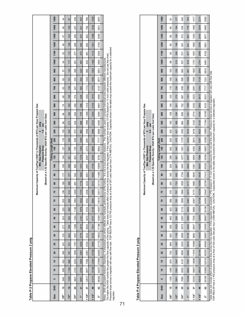
71
Ta
ble
P-3
Pro
pa
ne
Ele
va
ted
Pre
ss
ure
2 p
sig
Min
. G
as
Pre
ss
ure
:2
ps
ig
Pre
ss
ure
Dro
p:
1.0
ps
i
Siz
eE
HD
51
01
52
02
53
04
05
06
07
07
58
09
01
00
12
51
50
20
02
50
30
04
00
50
06
00
70
08
00
90
01
00
01
10
01
20
01
30
01
40
01
50
0
3/8
"
15
64
95
58
45
33
89
34
73
16
27
12
43
22
02
03
19
61
89
17
71
69
14
41
37
11
81
05
96
84
74
68
63
60
57
54
52
49
47
46
44
1/2
"
19
15
28
11
06
89
87
81
70
16
43
55
95
02
45
94
26
41
23
99
37
73
58
32
12
94
25
62
30
21
11
84
16
51
50
13
91
31
12
31
17
11
21
08
10
31
00
97
3/4
"
25
38
47
27
45
22
53
19
59
17
57
16
07
13
98
12
54
11
46
10
64
10
29
99
79
42
89
58
03
73
56
38
57
25
24
45
44
08
37
43
47
32
53
06
29
12
77
26
62
56
24
72
39
1"
31
66
81
47
56
39
00
33
87
30
35
27
75
24
10
21
61
19
76
18
32
17
70
17
16
16
20
15
37
13
79
12
60
10
94
98
28
98
77
96
98
63
85
92
55
45
22
49
74
73
45
44
37
42
14
07
1 1
/4"
37
12
61
78
97
77
35
66
38
75
72
45
23
34
54
44
07
23
72
43
45
23
33
83
23
33
05
12
89
72
59
72
37
32
06
11
84
81
68
91
46
61
31
41
20
21
11
31
04
39
85
93
48
91
85
58
22
79
27
66
1 1
/2"
46
21
57
41
51
98
12
38
11
07
06
95
65
87
22
75
41
67
37
61
45
56
84
54
89
53
12
50
05
47
45
42
40
38
66
33
42
29
86
27
23
23
54
21
04
19
19
17
75
16
59
15
63
14
82
14
12
13
51
12
98
12
49
12
06
2"
62
48
36
23
42
57
27
99
92
42
65
21
71
51
98
32
17
18
61
53
81
14
04
71
30
10
12
57
11
21
74
11
48
01
08
94
97
50
89
04
77
17
69
06
63
06
54
65
48
91
44
66
41
37
38
71
36
51
34
64
33
04
31
63
30
40
29
31
28
31
No
tes:
EH
D (
Eq
uiv
ale
nt
Hyd
rau
lic D
iam
ete
r)
A t
he
ore
tica
l siz
e w
hic
h r
efle
cts
th
e h
yd
rau
lic p
erf
orm
an
ce
of
the
tu
bin
g.
It
is n
ot
a t
rue
ph
ysic
al m
ea
su
re.
Th
is n
um
be
r is
use
d t
o c
om
pa
re in
div
idu
al siz
es b
etw
ee
n d
iffe
ren
t m
an
ufa
ctu
res.
Th
e h
igh
er
the
EH
D n
um
be
r th
e g
rea
ter
the
flo
w c
ap
acity o
f th
e p
ipin
g.
Ta
ble
do
es n
ot
inclu
de
eff
ect
of
pre
ssu
re d
rop
acro
ss t
he
lin
e r
eg
ula
tor.
If
the
re
gu
lato
r lo
ss e
xce
ed
s 1
/2 P
SI
(ba
se
d o
n 1
1 in
ch
ou
tle
t p
ressu
re)
D
o n
ot
use
th
is c
ha
rt.
Pre
ssu
re d
rop
s a
cro
ss a
re
gu
lato
r w
ill v
ary
with
flo
w r
ate
. F
GP
-RE
G-5
P h
as a
1/2
PS
I p
ressu
re d
rop
at
a f
low
of
30
7 c
ub
ic f
ee
t p
er
ho
ur
(77
4 M
BT
Uh
).
CA
UT
ION
: C
ap
acitie
s s
ho
wn
in
th
e t
ab
le m
ay e
xce
ed
th
e m
axim
um
ca
pa
city f
or
a s
ele
cte
d
reg
ula
tor.
Tu
bin
g L
en
gth
(fe
et)
Ma
xim
um
Ca
pa
cit
y o
f T
rac
Pip
e C
SS
T i
n T
ho
us
an
ds
of
BT
U p
er
Ho
ur
Pro
pa
ne
Ga
s
(Ba
se
d o
n a
1.5
2 S
pe
cif
ic G
rav
ity
/ 2
52
0 B
TU
pe
r c
ub
ic f
oo
t G
as
)
Ta
ble
P-4
Pro
pa
ne
Ele
va
ted
Pre
ss
ure
5 p
sig
Min
. G
as
Pre
ss
ure
:5
ps
ig
Pre
ss
ure
Dro
p:
3.5
ps
i
Siz
eE
HD
51
01
52
02
53
04
05
06
07
07
58
09
01
00
12
51
50
20
02
50
30
04
00
50
06
00
70
08
00
90
01
00
01
10
01
20
01
30
01
40
01
50
0
3/8
"
15
11
65
10
65
87
47
52
66
46
03
52
04
63
42
33
89
37
63
63
34
23
24
28
82
62
22
62
02
18
31
58
14
01
23
11
61
08
10
39
89
39
08
58
48
1
1/2
"
19
28
01
20
61
16
47
14
33
13
07
11
93
10
33
92
68
42
78
17
57
73
36
92
65
75
91
54
04
70
42
13
86
33
63
01
27
52
56
24
12
26
21
52
06
19
81
90
18
41
77
3/4
"
25
70
80
50
52
41
47
36
05
32
33
29
59
25
73
23
07
21
10
19
59
18
94
18
35
17
34
16
47
14
77
13
51
11
75
10
53
96
48
38
75
26
87
63
85
98
56
45
37
51
14
91
47
24
54
44
0
1"
31
12
34
98
94
57
20
76
25
95
61
05
13
04
45
53
99
33
65
33
38
73
27
33
17
12
99
42
84
22
54
72
33
12
02
31
81
41
65
91
44
11
29
01
18
11
09
41
02
49
67
91
88
77
84
18
07
77
97
54
1 1
/4"
37
23
34
21
66
07
13
60
81
18
16
10
58
99
68
38
40
77
53
56
88
96
38
76
17
35
98
25
64
45
36
14
80
44
39
23
81
43
41
83
12
52
71
42
43
22
22
32
06
11
93
01
82
21
73
11
65
11
58
21
52
01
46
61
41
7
1 1
/2"
46
40
63
52
86
25
23
32
22
01
66
18
01
41
64
30
14
20
51
26
90
11
57
41
07
06
10
33
91
00
06
94
28
89
39
79
86
72
83
62
97
56
25
51
30
44
36
39
63
36
15
33
42
31
25
29
45
27
91
26
60
25
46
24
45
23
54
22
74
2"
62
90
19
96
38
90
52
21
84
52
55
40
50
03
69
87
32
05
52
86
87
26
19
82
42
65
23
44
72
27
06
21
41
22
03
20
18
18
41
66
07
14
39
21
28
80
11
76
41
01
95
91
23
83
31
77
17
72
21
68
10
64
61
61
62
59
01
56
71
54
65
52
82
Ta
ble
do
es n
ot
inclu
de
eff
ect
of
pre
ssu
re d
rop
acro
ss t
he
lin
e r
eg
ula
tor.
If
the
re
gu
lato
r lo
ss e
xce
ed
s 1
PS
I (b
ase
d o
n 1
1 in
ch
ou
tle
t p
ressu
re)
Do
no
t u
se
th
is c
ha
rt.
Pre
ssu
re d
rop
s a
cro
ss a
re
gu
lato
r w
ill v
ary
with
flo
w r
ate
.
FG
P-R
EG
-5P
ha
s a
1 P
SI
pre
ssu
re d
rop
at
a f
low
of
43
4 c
ub
ic f
ee
t p
er
ho
ur
(10
94
MB
TU
h).
C
AU
TIO
N:
Ca
pa
citie
s s
ho
wn
in
th
e t
ab
le m
ay e
xce
ed
th
e m
axim
um
ca
pa
city f
or
a s
ele
cte
d r
eg
ula
tor.
Tu
bin
g L
en
gth
(fe
et)
(Ba
se
d o
n a
1.5
2 S
pe
cif
ic G
rav
ity
/ 2
52
0 B
TU
pe
r c
ub
ic f
oo
t G
as
)
Ma
xim
um
Ca
pa
cit
y o
f T
rac
Pip
e C
SS
T i
n T
ho
us
an
ds
of
BT
U p
er
Ho
ur
Pro
pa
ne
Ga
s
111743_OmegaFlex_Txt:111743_OmegaFlex_Txt 5/28/09 11:57 AM Page 71
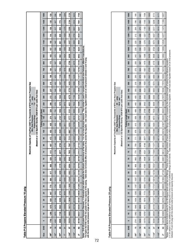
72
Ta
ble
P-5
Pro
pa
ne
Ele
va
ted
Pre
ss
ure
10
ps
ig
Min
. G
as
Pre
ss
ure
:1
0p
sig
Pre
ss
ure
Dro
p:
7.0
ps
i
Siz
eE
HD
51
01
52
02
53
04
05
06
07
07
58
09
01
00
12
51
50
20
02
50
30
04
00
50
06
00
70
08
00
90
01
00
01
10
01
20
01
30
01
40
01
50
0
3/8
"
15
17
69
12
89
10
70
93
98
47
77
96
84
61
75
68
52
95
13
49
74
72
45
04
05
37
43
28
29
62
72
23
72
15
19
81
84
17
31
65
15
71
50
14
41
39
13
51
30
1/2
"
19
40
91
29
75
24
70
21
64
19
52
17
95
15
74
14
20
13
06
12
16
11
78
11
45
10
85
10
32
93
38
57
75
06
78
62
45
46
49
24
53
42
13
97
37
53
58
34
23
29
31
73
07
29
8
3/4
"
25
96
99
71
06
59
23
52
06
47
10
43
40
38
14
34
50
31
79
29
67
28
77
27
94
26
50
25
28
22
86
21
07
18
52
16
75
15
44
13
57
12
27
11
30
10
54
99
49
42
89
98
61
82
88
00
77
37
49
1"
31
16
38
71
20
36
10
04
98
84
18
00
57
38
16
49
55
88
05
42
15
06
24
91
04
77
04
52
74
31
93
91
13
60
53
17
32
87
22
64
92
33
12
10
91
94
61
81
61
71
21
62
41
55
01
48
51
42
81
37
91
33
31
29
4
1 1
/4"
37
25
22
91
86
83
15
67
31
38
36
12
56
01
16
05
10
24
59
30
28
59
48
04
07
80
27
58
77
21
06
88
76
25
25
77
75
10
14
63
14
27
83
77
83
42
93
16
82
96
42
79
82
65
82
54
02
43
72
34
62
26
62
19
42
12
9
1 1
/2"
46
47
72
03
46
45
28
72
82
51
53
22
69
02
08
58
18
26
11
64
74
15
14
21
41
02
13
65
91
32
58
12
55
71
19
60
10
78
89
91
88
68
37
83
27
19
96
30
35
68
65
22
64
86
74
57
64
33
34
12
83
95
03
79
53
65
73
53
43
42
3
2"
62
90
19
96
60
37
55
53
04
91
05
44
63
94
12
93
36
51
63
31
95
30
70
62
87
49
27
91
32
71
53
25
82
02
46
83
22
43
82
07
57
18
35
51
66
86
15
43
51
36
49
12
40
81
14
77
10
74
61
01
49
96
52
92
26
88
58
85
34
82
47
79
91
77
58
No
tes:
EH
D (
Eq
uiv
ale
nt
Hyd
rau
lic D
iam
ete
r)
A t
he
ore
tica
l siz
e w
hic
h r
efle
cts
th
e h
yd
rau
lic p
erf
orm
an
ce
of
the
tu
bin
g.
It
is n
ot
a t
rue
ph
ysic
al m
ea
su
re.
Th
is n
um
be
r is
use
d t
o c
om
pa
re in
div
idu
al siz
es b
etw
ee
n d
iffe
ren
t m
an
ufa
ctu
res.
Th
e h
igh
er
the
EH
D n
um
be
r th
e g
rea
ter
the
flo
w c
ap
acity o
f th
e p
ipin
g.
Ta
ble
do
es n
ot
inclu
de
eff
ect
of
pre
ssu
re d
rop
acro
ss t
he
re
gu
lato
r.
Use
r m
ust
siz
e t
he
re
gu
lato
r b
ase
d o
n a
n in
let
pre
ssu
re b
etw
ee
n 3
an
d 1
0 p
sig
with
th
e d
esire
d o
utle
t p
ressu
re r
an
ge
an
d c
ap
acity r
eq
uire
d.
Tu
bin
g L
en
gth
(fe
et)
Ma
xim
um
Ca
pa
cit
y o
f T
rac
Pip
e C
SS
T i
n T
ho
us
an
ds
of
BT
U p
er
Ho
ur
Pro
pa
ne
Ga
s
(Ba
se
d o
n a
1.5
2 S
pe
cif
ic G
rav
ity
/ 2
52
0 B
TU
pe
r c
ub
ic f
oo
t G
as
)
Ta
ble
P-6
Pro
pa
ne
Ele
va
ted
Pre
ss
ure
25
ps
ig
Min
. G
as
Pre
ss
ure
:2
5p
sig
Pre
ss
ure
Dro
p:
10
.0p
si
Siz
eE
HD
51
01
52
02
53
04
05
06
07
07
58
09
01
00
12
51
50
20
02
50
30
04
00
50
06
00
70
08
00
90
01
00
01
10
01
20
01
30
01
40
01
50
0
3/8
"
15
27
41
19
82
16
40
14
34
12
92
11
87
10
37
93
68
58
80
07
74
75
07
11
67
66
10
55
94
89
44
04
05
35
33
18
29
32
72
25
52
42
23
02
20
21
22
04
19
61
90
1/2
"
19
59
39
43
30
36
00
31
59
28
53
26
25
23
02
20
80
19
14
17
84
17
29
16
78
15
91
15
17
13
70
12
60
11
05
99
99
18
80
67
28
67
06
24
58
75
57
53
05
08
48
84
70
45
44
42
3/4
"
25
14
77
51
07
87
89
72
78
74
71
15
65
50
57
49
51
95
47
81
44
58
43
21
41
96
39
77
37
92
34
26
31
54
27
68
25
02
23
02
20
20
18
26
16
81
15
67
14
76
13
98
13
33
12
76
12
27
11
83
11
45
11
08
1"
31
25
11
21
83
91
15
32
81
34
69
12
18
51
12
25
98
64
89
23
82
22
76
71
74
37
72
24
68
52
65
34
59
12
54
46
47
86
43
29
39
88
35
05
31
70
29
21
27
25
25
66
24
35
23
21
22
24
21
39
20
63
19
97
19
35
1 1
/4"
37
39
39
02
89
36
24
15
92
12
57
19
24
81
77
47
15
61
61
41
39
13
03
71
21
74
11
80
51
14
71
10
88
51
03
86
94
05
86
72
76
30
69
09
63
69
56
05
50
74
46
80
43
70
41
16
39
08
37
29
35
73
34
37
33
17
32
09
31
13
1 1
/2"
46
70
13
95
10
92
42
44
73
72
16
33
60
83
09
20
27
10
92
44
80
22
52
22
09
89
20
33
91
97
47
18
71
31
78
32
16
10
31
48
15
12
98
91
17
29
10
79
29
46
28
54
37
86
17
32
66
89
26
53
16
22
45
95
85
72
55
51
95
33
65
17
1
2"
62
12
63
76
93
90
87
89
35
69
78
36
34
21
58
65
55
18
54
47
12
64
35
86
40
80
13
96
12
38
53
23
66
35
35
01
93
18
27
29
43
52
60
23
23
64
92
18
73
19
33
61
75
73
16
25
41
52
14
14
36
81
36
62
13
05
91
25
36
12
07
71
16
70
11
30
61
09
77
*No
tes:
Ta
ble
s a
bo
ve
in
clu
de
lo
sse
s f
or
fou
r 9
0-d
eg
ree
be
nd
s a
nd
tw
o e
nd
fittin
gs.
Tu
bin
g r
un
s w
ith
la
rge
r n
um
be
rs o
f b
en
ds a
nd
/or
fitt
ing
s s
ha
ll b
e in
cre
ase
d b
y t
he
eq
uiv
ale
nt
len
gth
of
tub
ing
to
th
e f
ollo
win
g e
qu
atio
n:
L=
1.3
n w
he
re L
is t
he
ad
ditio
na
l le
ng
th o
f tu
bin
g a
nd
n is t
he
nu
mb
er
of
ad
ditio
na
l fitt
ing
s a
nd
/or
be
nd
s.
Ta
ble
do
es n
ot
inclu
de
eff
ect
of
pre
ssu
re d
rop
acro
ss t
he
lin
e r
eg
ula
tor.
U
se
r m
ust
siz
e r
eg
ula
tor
ba
se
d o
n a
n in
let
pre
ssu
re
be
twe
en
15
an
d 2
5 p
sig
with
th
e d
esire
d o
utle
t p
ressu
re a
nd
ca
pa
city r
eq
uire
d.
Ma
xim
um
Ca
pa
cit
y o
f T
rac
Pip
e C
SS
T i
n T
ho
us
an
ds
of
BT
U p
er
Ho
ur
Pro
pa
ne
Ga
s
(Ba
se
d o
n a
1.5
2 S
pe
cif
ic G
rav
ity
/ 2
52
0 B
TU
pe
r c
ub
ic f
oo
t G
as
)
Tu
bin
g L
en
gth
(fe
et)
111743_OmegaFlex_Txt:111743_OmegaFlex_Txt 5/28/09 11:57 AM Page 72
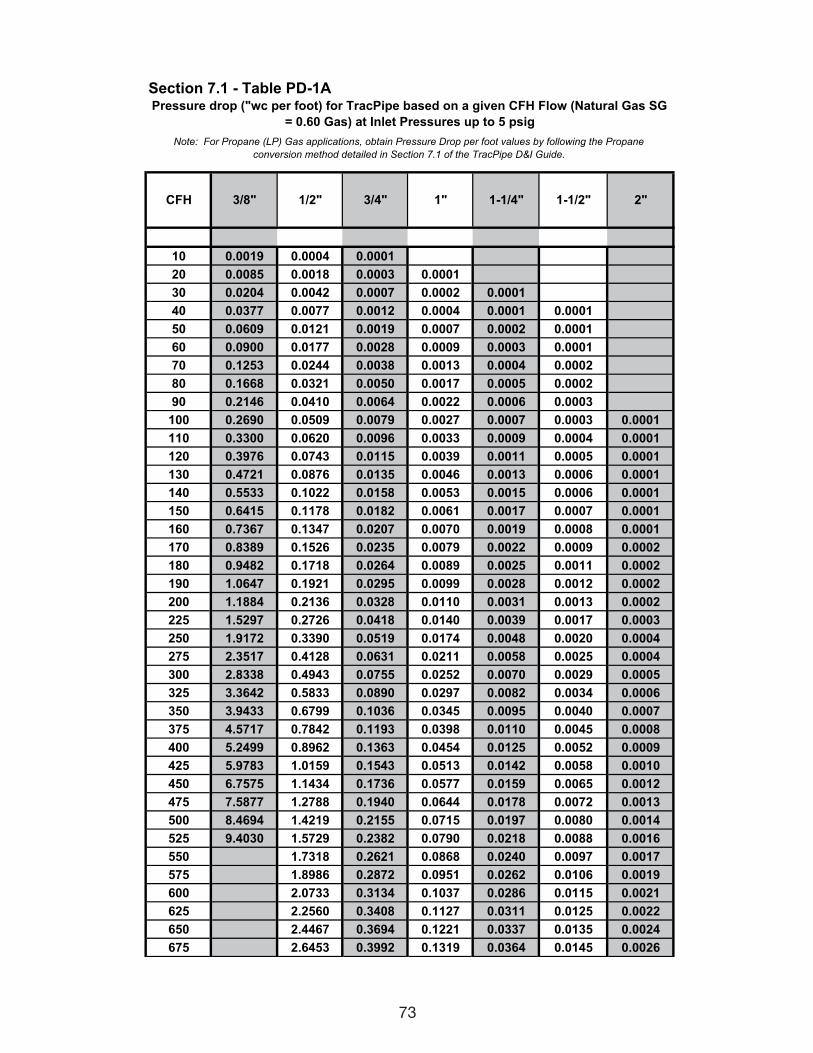
73
Section 7.1 - Table PD-1A
CFH 3/8" 1/2" 3/4" 1" 1-1/4" 1-1/2" 2"
10 0.0019 0.0004 0.0001
20 0.0085 0.0018 0.0003 0.0001
30 0.0204 0.0042 0.0007 0.0002 0.0001
40 0.0377 0.0077 0.0012 0.0004 0.0001 0.0001
50 0.0609 0.0121 0.0019 0.0007 0.0002 0.0001
60 0.0900 0.0177 0.0028 0.0009 0.0003 0.0001
70 0.1253 0.0244 0.0038 0.0013 0.0004 0.0002
80 0.1668 0.0321 0.0050 0.0017 0.0005 0.0002
90 0.2146 0.0410 0.0064 0.0022 0.0006 0.0003
100 0.2690 0.0509 0.0079 0.0027 0.0007 0.0003 0.0001
110 0.3300 0.0620 0.0096 0.0033 0.0009 0.0004 0.0001
120 0.3976 0.0743 0.0115 0.0039 0.0011 0.0005 0.0001
130 0.4721 0.0876 0.0135 0.0046 0.0013 0.0006 0.0001
140 0.5533 0.1022 0.0158 0.0053 0.0015 0.0006 0.0001
150 0.6415 0.1178 0.0182 0.0061 0.0017 0.0007 0.0001
160 0.7367 0.1347 0.0207 0.0070 0.0019 0.0008 0.0001
170 0.8389 0.1526 0.0235 0.0079 0.0022 0.0009 0.0002
180 0.9482 0.1718 0.0264 0.0089 0.0025 0.0011 0.0002
190 1.0647 0.1921 0.0295 0.0099 0.0028 0.0012 0.0002
200 1.1884 0.2136 0.0328 0.0110 0.0031 0.0013 0.0002
225 1.5297 0.2726 0.0418 0.0140 0.0039 0.0017 0.0003
250 1.9172 0.3390 0.0519 0.0174 0.0048 0.0020 0.0004
275 2.3517 0.4128 0.0631 0.0211 0.0058 0.0025 0.0004
300 2.8338 0.4943 0.0755 0.0252 0.0070 0.0029 0.0005
325 3.3642 0.5833 0.0890 0.0297 0.0082 0.0034 0.0006
350 3.9433 0.6799 0.1036 0.0345 0.0095 0.0040 0.0007
375 4.5717 0.7842 0.1193 0.0398 0.0110 0.0045 0.0008
400 5.2499 0.8962 0.1363 0.0454 0.0125 0.0052 0.0009
425 5.9783 1.0159 0.1543 0.0513 0.0142 0.0058 0.0010
450 6.7575 1.1434 0.1736 0.0577 0.0159 0.0065 0.0012
475 7.5877 1.2788 0.1940 0.0644 0.0178 0.0072 0.0013
500 8.4694 1.4219 0.2155 0.0715 0.0197 0.0080 0.0014
525 9.4030 1.5729 0.2382 0.0790 0.0218 0.0088 0.0016
550 1.7318 0.2621 0.0868 0.0240 0.0097 0.0017
575 1.8986 0.2872 0.0951 0.0262 0.0106 0.0019
600 2.0733 0.3134 0.1037 0.0286 0.0115 0.0021
625 2.2560 0.3408 0.1127 0.0311 0.0125 0.0022
650 2.4467 0.3694 0.1221 0.0337 0.0135 0.0024
675 2.6453 0.3992 0.1319 0.0364 0.0145 0.0026
Pressure drop ("wc per foot) for TracPipe based on a given CFH Flow (Natural Gas SG
= 0.60 Gas) at Inlet Pressures up to 5 psig
Note: For Propane (LP) Gas applications, obtain Pressure Drop per foot values by following the Propane
conversion method detailed in Section 7.1 of the TracPipe D&I Guide.
111743_OmegaFlex_Txt:111743_OmegaFlex_Txt 5/28/09 11:57 AM Page 73
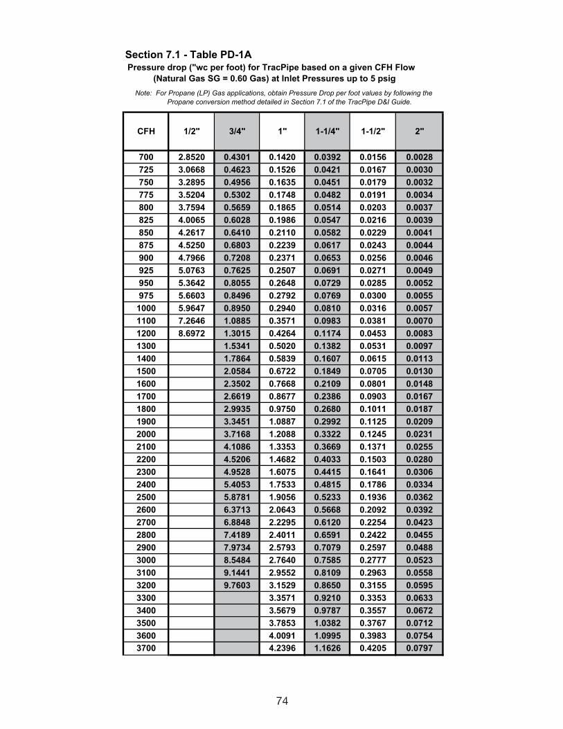
74
Section 7.1 - Table PD-1A
CFH 1/2" 3/4" 1" 1-1/4" 1-1/2" 2"
700 2.8520 0.4301 0.1420 0.0392 0.0156 0.0028
725 3.0668 0.4623 0.1526 0.0421 0.0167 0.0030
750 3.2895 0.4956 0.1635 0.0451 0.0179 0.0032
775 3.5204 0.5302 0.1748 0.0482 0.0191 0.0034
800 3.7594 0.5659 0.1865 0.0514 0.0203 0.0037
825 4.0065 0.6028 0.1986 0.0547 0.0216 0.0039
850 4.2617 0.6410 0.2110 0.0582 0.0229 0.0041
875 4.5250 0.6803 0.2239 0.0617 0.0243 0.0044
900 4.7966 0.7208 0.2371 0.0653 0.0256 0.0046
925 5.0763 0.7625 0.2507 0.0691 0.0271 0.0049
950 5.3642 0.8055 0.2648 0.0729 0.0285 0.0052
975 5.6603 0.8496 0.2792 0.0769 0.0300 0.0055
1000 5.9647 0.8950 0.2940 0.0810 0.0316 0.0057
1100 7.2646 1.0885 0.3571 0.0983 0.0381 0.0070
1200 8.6972 1.3015 0.4264 0.1174 0.0453 0.0083
1300 1.5341 0.5020 0.1382 0.0531 0.0097
1400 1.7864 0.5839 0.1607 0.0615 0.0113
1500 2.0584 0.6722 0.1849 0.0705 0.0130
1600 2.3502 0.7668 0.2109 0.0801 0.0148
1700 2.6619 0.8677 0.2386 0.0903 0.0167
1800 2.9935 0.9750 0.2680 0.1011 0.0187
1900 3.3451 1.0887 0.2992 0.1125 0.0209
2000 3.7168 1.2088 0.3322 0.1245 0.0231
2100 4.1086 1.3353 0.3669 0.1371 0.0255
2200 4.5206 1.4682 0.4033 0.1503 0.0280
2300 4.9528 1.6075 0.4415 0.1641 0.0306
2400 5.4053 1.7533 0.4815 0.1786 0.0334
2500 5.8781 1.9056 0.5233 0.1936 0.0362
2600 6.3713 2.0643 0.5668 0.2092 0.0392
2700 6.8848 2.2295 0.6120 0.2254 0.0423
2800 7.4189 2.4011 0.6591 0.2422 0.0455
2900 7.9734 2.5793 0.7079 0.2597 0.0488
3000 8.5484 2.7640 0.7585 0.2777 0.0523
3100 9.1441 2.9552 0.8109 0.2963 0.0558
3200 9.7603 3.1529 0.8650 0.3155 0.0595
3300 3.3571 0.9210 0.3353 0.0633
3400 3.5679 0.9787 0.3557 0.0672
3500 3.7853 1.0382 0.3767 0.0712
3600 4.0091 1.0995 0.3983 0.0754
3700 4.2396 1.1626 0.4205 0.0797
Pressure drop ("wc per foot) for TracPipe based on a given CFH Flow
Note: For Propane (LP) Gas applications, obtain Pressure Drop per foot values by following the
(Natural Gas SG = 0.60 Gas) at Inlet Pressures up to 5 psig
Propane conversion method detailed in Section 7.1 of the TracPipe D&I Guide.
111743_OmegaFlex_Txt:111743_OmegaFlex_Txt 5/28/09 11:57 AM Page 74
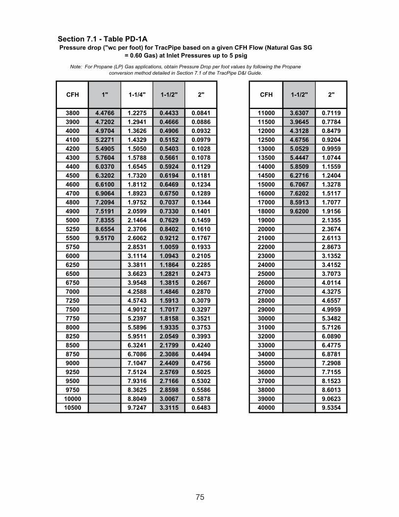
75
Section 7.1 - Table PD-1A
CFH 1" 1-1/4" 1-1/2" 2" CFH 1-1/2" 2"
3800 4.4766 1.2275 0.4433 0.0841 11000 3.6307 0.7119
3900 4.7202 1.2941 0.4666 0.0886 11500 3.9645 0.7784
4000 4.9704 1.3626 0.4906 0.0932 12000 4.3128 0.8479
4100 5.2271 1.4329 0.5152 0.0979 12500 4.6756 0.9204
4200 5.4905 1.5050 0.5403 0.1028 13000 5.0529 0.9959
4300 5.7604 1.5788 0.5661 0.1078 13500 5.4447 1.0744
4400 6.0370 1.6545 0.5924 0.1129 14000 5.8509 1.1559
4500 6.3202 1.7320 0.6194 0.1181 14500 6.2716 1.2404
4600 6.6100 1.8112 0.6469 0.1234 15000 6.7067 1.3278
4700 6.9064 1.8923 0.6750 0.1289 16000 7.6202 1.5117
4800 7.2094 1.9752 0.7037 0.1344 17000 8.5913 1.7077
4900 7.5191 2.0599 0.7330 0.1401 18000 9.6200 1.9156
5000 7.8355 2.1464 0.7629 0.1459 19000 2.1355
5250 8.6554 2.3706 0.8402 0.1610 20000 2.3674
5500 9.5170 2.6062 0.9212 0.1767 21000 2.6113
5750 2.8531 1.0059 0.1933 22000 2.8673
6000 3.1114 1.0943 0.2105 23000 3.1352
6250 3.3811 1.1864 0.2285 24000 3.4152
6500 3.6623 1.2821 0.2473 25000 3.7073
6750 3.9548 1.3815 0.2667 26000 4.0114
7000 4.2588 1.4846 0.2870 27000 4.3275
7250 4.5743 1.5913 0.3079 28000 4.6557
7500 4.9012 1.7017 0.3297 29000 4.9959
7750 5.2397 1.8158 0.3521 30000 5.3482
8000 5.5896 1.9335 0.3753 31000 5.7126
8250 5.9511 2.0549 0.3993 32000 6.0890
8500 6.3241 2.1799 0.4240 33000 6.4775
8750 6.7086 2.3086 0.4494 34000 6.8781
9000 7.1047 2.4409 0.4756 35000 7.2908
9250 7.5124 2.5769 0.5025 36000 7.7155
9500 7.9316 2.7166 0.5302 37000 8.1523
9750 8.3625 2.8598 0.5586 38000 8.6013
10000 8.8049 3.0067 0.5878 39000 9.0623
10500 9.7247 3.3115 0.6483 40000 9.5354
Note: For Propane (LP) Gas applications, obtain Pressure Drop per foot values by following the Propane
conversion method detailed in Section 7.1 of the TracPipe D&I Guide.
Pressure drop ("wc per foot) for TracPipe based on a given CFH Flow (Natural Gas SG
= 0.60 Gas) at Inlet Pressures up to 5 psig
111743_OmegaFlex_Txt:111743_OmegaFlex_Txt 5/28/09 11:57 AM Page 75
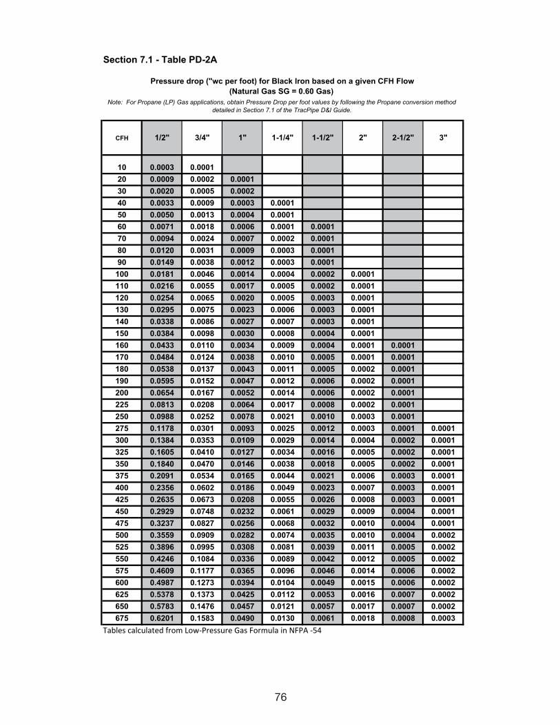
76
Section 7.1 - Table PD-2A
CFH 1/2" 3/4" 1" 1-1/4" 1-1/2" 2" 2-1/2" 3"
10 0.0003 0.0001
20 0.0009 0.0002 0.0001
30 0.0020 0.0005 0.0002
40 0.0033 0.0009 0.0003 0.0001
50 0.0050 0.0013 0.0004 0.0001
60 0.0071 0.0018 0.0006 0.0001 0.0001
70 0.0094 0.0024 0.0007 0.0002 0.0001
80 0.0120 0.0031 0.0009 0.0003 0.0001
90 0.0149 0.0038 0.0012 0.0003 0.0001
100 0.0181 0.0046 0.0014 0.0004 0.0002 0.0001
110 0.0216 0.0055 0.0017 0.0005 0.0002 0.0001
120 0.0254 0.0065 0.0020 0.0005 0.0003 0.0001
130 0.0295 0.0075 0.0023 0.0006 0.0003 0.0001
140 0.0338 0.0086 0.0027 0.0007 0.0003 0.0001
150 0.0384 0.0098 0.0030 0.0008 0.0004 0.0001
160 0.0433 0.0110 0.0034 0.0009 0.0004 0.0001 0.0001
170 0.0484 0.0124 0.0038 0.0010 0.0005 0.0001 0.0001
180 0.0538 0.0137 0.0043 0.0011 0.0005 0.0002 0.0001
190 0.0595 0.0152 0.0047 0.0012 0.0006 0.0002 0.0001
200 0.0654 0.0167 0.0052 0.0014 0.0006 0.0002 0.0001
225 0.0813 0.0208 0.0064 0.0017 0.0008 0.0002 0.0001
250 0.0988 0.0252 0.0078 0.0021 0.0010 0.0003 0.0001
275 0.1178 0.0301 0.0093 0.0025 0.0012 0.0003 0.0001 0.0001
300 0.1384 0.0353 0.0109 0.0029 0.0014 0.0004 0.0002 0.0001
325 0.1605 0.0410 0.0127 0.0034 0.0016 0.0005 0.0002 0.0001
350 0.1840 0.0470 0.0146 0.0038 0.0018 0.0005 0.0002 0.0001
375 0.2091 0.0534 0.0165 0.0044 0.0021 0.0006 0.0003 0.0001
400 0.2356 0.0602 0.0186 0.0049 0.0023 0.0007 0.0003 0.0001
425 0.2635 0.0673 0.0208 0.0055 0.0026 0.0008 0.0003 0.0001
450 0.2929 0.0748 0.0232 0.0061 0.0029 0.0009 0.0004 0.0001
475 0.3237 0.0827 0.0256 0.0068 0.0032 0.0010 0.0004 0.0001
500 0.3559 0.0909 0.0282 0.0074 0.0035 0.0010 0.0004 0.0002
525 0.3896 0.0995 0.0308 0.0081 0.0039 0.0011 0.0005 0.0002
550 0.4246 0.1084 0.0336 0.0089 0.0042 0.0012 0.0005 0.0002
575 0.4609 0.1177 0.0365 0.0096 0.0046 0.0014 0.0006 0.0002
600 0.4987 0.1273 0.0394 0.0104 0.0049 0.0015 0.0006 0.0002
625 0.5378 0.1373 0.0425 0.0112 0.0053 0.0016 0.0007 0.0002
650 0.5783 0.1476 0.0457 0.0121 0.0057 0.0017 0.0007 0.0002
675 0.6201 0.1583 0.0490 0.0130 0.0061 0.0018 0.0008 0.0003
����������������� �������� ��� �������� ���������������
Pressure drop ("wc per foot) for Black Iron based on a given CFH Flow
(Natural Gas SG = 0.60 Gas)
Note: For Propane (LP) Gas applications, obtain Pressure Drop per foot values by following the Propane conversion method
detailed in Section 7.1 of the TracPipe D&I Guide.
111743_OmegaFlex_Txt:111743_OmegaFlex_Txt 5/28/09 11:57 AM Page 76
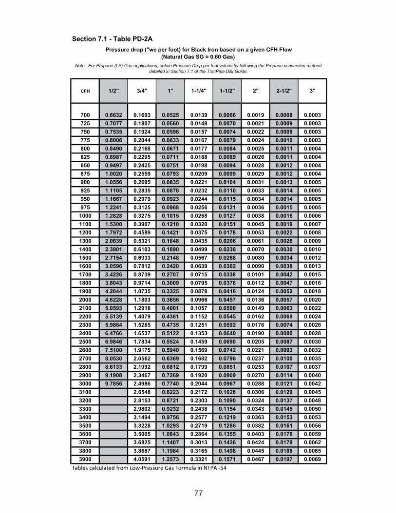
77
Section 7.1 - Table PD-2A
CFH 1/2" 3/4" 1" 1-1/4" 1-1/2" 2" 2-1/2" 3"
700 0.6632 0.1693 0.0525 0.0139 0.0066 0.0019 0.0008 0.0003
725 0.7077 0.1807 0.0560 0.0148 0.0070 0.0021 0.0009 0.0003
750 0.7535 0.1924 0.0596 0.0157 0.0074 0.0022 0.0009 0.0003
775 0.8006 0.2044 0.0633 0.0167 0.0079 0.0024 0.0010 0.0003
800 0.8490 0.2168 0.0671 0.0177 0.0084 0.0025 0.0011 0.0004
825 0.8987 0.2295 0.0711 0.0188 0.0089 0.0026 0.0011 0.0004
850 0.9497 0.2425 0.0751 0.0198 0.0094 0.0028 0.0012 0.0004
875 1.0020 0.2559 0.0793 0.0209 0.0099 0.0029 0.0012 0.0004
900 1.0556 0.2695 0.0835 0.0221 0.0104 0.0031 0.0013 0.0005
925 1.1105 0.2835 0.0878 0.0232 0.0110 0.0033 0.0014 0.0005
950 1.1667 0.2979 0.0923 0.0244 0.0115 0.0034 0.0014 0.0005
975 1.2241 0.3125 0.0968 0.0256 0.0121 0.0036 0.0015 0.0005
1000 1.2828 0.3275 0.1015 0.0268 0.0127 0.0038 0.0016 0.0006
1100 1.5300 0.3907 0.1210 0.0320 0.0151 0.0045 0.0019 0.0007
1200 1.7972 0.4589 0.1421 0.0375 0.0178 0.0053 0.0022 0.0008
1300 2.0839 0.5321 0.1648 0.0435 0.0206 0.0061 0.0026 0.0009
1400 2.3901 0.6103 0.1890 0.0499 0.0236 0.0070 0.0030 0.0010
1500 2.7154 0.6933 0.2148 0.0567 0.0268 0.0080 0.0034 0.0012
1600 3.0596 0.7812 0.2420 0.0639 0.0302 0.0090 0.0038 0.0013
1700 3.4226 0.8739 0.2707 0.0715 0.0338 0.0101 0.0042 0.0015
1800 3.8043 0.9714 0.3009 0.0795 0.0376 0.0112 0.0047 0.0016
1900 4.2044 1.0735 0.3325 0.0878 0.0416 0.0124 0.0052 0.0018
2000 4.6228 1.1803 0.3656 0.0966 0.0457 0.0136 0.0057 0.0020
2100 5.0593 1.2918 0.4001 0.1057 0.0500 0.0149 0.0063 0.0022
2200 5.5139 1.4079 0.4361 0.1152 0.0545 0.0162 0.0068 0.0024
2300 5.9864 1.5285 0.4735 0.1251 0.0592 0.0176 0.0074 0.0026
2400 6.4766 1.6537 0.5122 0.1353 0.0640 0.0190 0.0080 0.0028
2500 6.9846 1.7834 0.5524 0.1459 0.0690 0.0205 0.0087 0.0030
2600 7.5100 1.9175 0.5940 0.1569 0.0742 0.0221 0.0093 0.0032
2700 8.0530 2.0562 0.6369 0.1682 0.0796 0.0237 0.0100 0.0035
2800 8.6133 2.1992 0.6812 0.1799 0.0851 0.0253 0.0107 0.0037
2900 9.1908 2.3467 0.7269 0.1920 0.0909 0.0270 0.0114 0.0040
3000 9.7856 2.4986 0.7740 0.2044 0.0967 0.0288 0.0121 0.0042
3100 2.6548 0.8223 0.2172 0.1028 0.0306 0.0129 0.0045
3200 2.8153 0.8721 0.2303 0.1090 0.0324 0.0137 0.0048
3300 2.9802 0.9232 0.2438 0.1154 0.0343 0.0145 0.0050
3400 3.1494 0.9756 0.2577 0.1219 0.0363 0.0153 0.0053
3500 3.3228 1.0293 0.2719 0.1286 0.0382 0.0161 0.0056
3600 3.5005 1.0843 0.2864 0.1355 0.0403 0.0170 0.0059
3700 3.6825 1.1407 0.3013 0.1426 0.0424 0.0179 0.0062
3800 3.8687 1.1984 0.3165 0.1498 0.0445 0.0188 0.0065
3900 4.0591 1.2573 0.3321 0.1571 0.0467 0.0197 0.0069
����������������� �������� ��� �������� ���������������
Note: For Propane (LP) Gas applications, obtain Pressure Drop per foot values by following the Propane conversion method
detailed in Section 7.1 of the TracPipe D&I Guide.
Pressure drop ("wc per foot) for Black Iron based on a given CFH Flow
(Natural Gas SG = 0.60 Gas)
111743_OmegaFlex_Txt:111743_OmegaFlex_Txt 5/28/09 11:57 AM Page 77
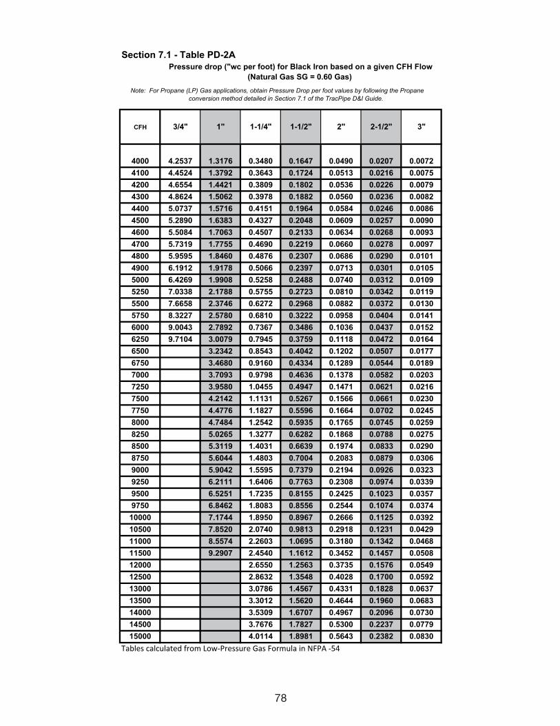
78
Section 7.1 - Table PD-2A
CFH 3/4" 1" 1-1/4" 1-1/2" 2" 2-1/2" 3"
4000 4.2537 1.3176 0.3480 0.1647 0.0490 0.0207 0.0072
4100 4.4524 1.3792 0.3643 0.1724 0.0513 0.0216 0.0075
4200 4.6554 1.4421 0.3809 0.1802 0.0536 0.0226 0.0079
4300 4.8624 1.5062 0.3978 0.1882 0.0560 0.0236 0.0082
4400 5.0737 1.5716 0.4151 0.1964 0.0584 0.0246 0.0086
4500 5.2890 1.6383 0.4327 0.2048 0.0609 0.0257 0.0090
4600 5.5084 1.7063 0.4507 0.2133 0.0634 0.0268 0.0093
4700 5.7319 1.7755 0.4690 0.2219 0.0660 0.0278 0.0097
4800 5.9595 1.8460 0.4876 0.2307 0.0686 0.0290 0.0101
4900 6.1912 1.9178 0.5066 0.2397 0.0713 0.0301 0.0105
5000 6.4269 1.9908 0.5258 0.2488 0.0740 0.0312 0.0109
5250 7.0338 2.1788 0.5755 0.2723 0.0810 0.0342 0.0119
5500 7.6658 2.3746 0.6272 0.2968 0.0882 0.0372 0.0130
5750 8.3227 2.5780 0.6810 0.3222 0.0958 0.0404 0.0141
6000 9.0043 2.7892 0.7367 0.3486 0.1036 0.0437 0.0152
6250 9.7104 3.0079 0.7945 0.3759 0.1118 0.0472 0.0164
6500 3.2342 0.8543 0.4042 0.1202 0.0507 0.0177
6750 3.4680 0.9160 0.4334 0.1289 0.0544 0.0189
7000 3.7093 0.9798 0.4636 0.1378 0.0582 0.0203
7250 3.9580 1.0455 0.4947 0.1471 0.0621 0.0216
7500 4.2142 1.1131 0.5267 0.1566 0.0661 0.0230
7750 4.4776 1.1827 0.5596 0.1664 0.0702 0.0245
8000 4.7484 1.2542 0.5935 0.1765 0.0745 0.0259
8250 5.0265 1.3277 0.6282 0.1868 0.0788 0.0275
8500 5.3119 1.4031 0.6639 0.1974 0.0833 0.0290
8750 5.6044 1.4803 0.7004 0.2083 0.0879 0.0306
9000 5.9042 1.5595 0.7379 0.2194 0.0926 0.0323
9250 6.2111 1.6406 0.7763 0.2308 0.0974 0.0339
9500 6.5251 1.7235 0.8155 0.2425 0.1023 0.0357
9750 6.8462 1.8083 0.8556 0.2544 0.1074 0.0374
10000 7.1744 1.8950 0.8967 0.2666 0.1125 0.0392
10500 7.8520 2.0740 0.9813 0.2918 0.1231 0.0429
11000 8.5574 2.2603 1.0695 0.3180 0.1342 0.0468
11500 9.2907 2.4540 1.1612 0.3452 0.1457 0.0508
12000 2.6550 1.2563 0.3735 0.1576 0.0549
12500 2.8632 1.3548 0.4028 0.1700 0.0592
13000 3.0786 1.4567 0.4331 0.1828 0.0637
13500 3.3012 1.5620 0.4644 0.1960 0.0683
14000 3.5309 1.6707 0.4967 0.2096 0.0730
14500 3.7676 1.7827 0.5300 0.2237 0.0779
15000 4.0114 1.8981 0.5643 0.2382 0.0830
����������������� �������� ��� �������� ���������������
Note: For Propane (LP) Gas applications, obtain Pressure Drop per foot values by following the Propane
Pressure drop ("wc per foot) for Black Iron based on a given CFH Flow
(Natural Gas SG = 0.60 Gas)
conversion method detailed in Section 7.1 of the TracPipe D&I Guide.
111743_OmegaFlex_Txt:111743_OmegaFlex_Txt 5/28/09 11:57 AM Page 78
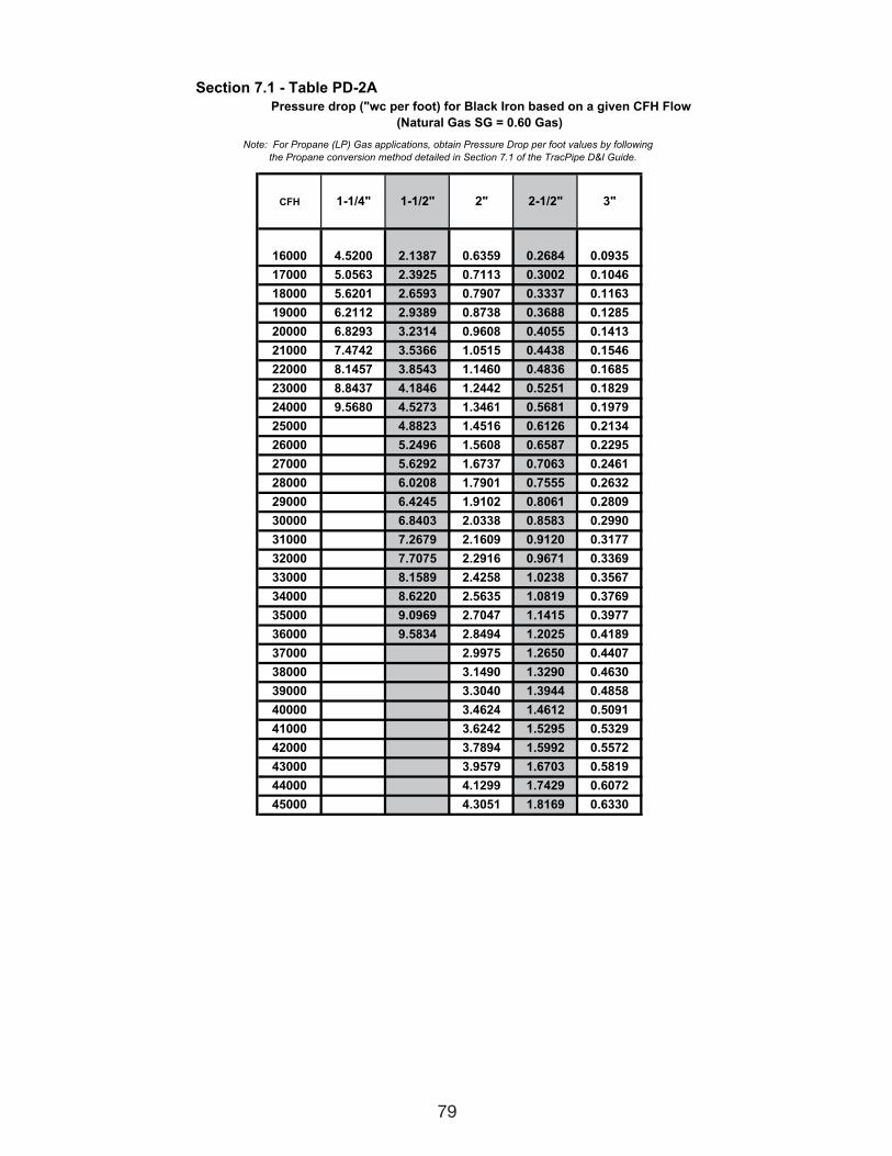
79
Section 7.1 - Table PD-2A
CFH 1-1/4" 1-1/2" 2" 2-1/2" 3"
16000 4.5200 2.1387 0.6359 0.2684 0.0935
17000 5.0563 2.3925 0.7113 0.3002 0.1046
18000 5.6201 2.6593 0.7907 0.3337 0.1163
19000 6.2112 2.9389 0.8738 0.3688 0.1285
20000 6.8293 3.2314 0.9608 0.4055 0.1413
21000 7.4742 3.5366 1.0515 0.4438 0.1546
22000 8.1457 3.8543 1.1460 0.4836 0.1685
23000 8.8437 4.1846 1.2442 0.5251 0.1829
24000 9.5680 4.5273 1.3461 0.5681 0.1979
25000 4.8823 1.4516 0.6126 0.2134
26000 5.2496 1.5608 0.6587 0.2295
27000 5.6292 1.6737 0.7063 0.2461
28000 6.0208 1.7901 0.7555 0.2632
29000 6.4245 1.9102 0.8061 0.2809
30000 6.8403 2.0338 0.8583 0.2990
31000 7.2679 2.1609 0.9120 0.3177
32000 7.7075 2.2916 0.9671 0.3369
33000 8.1589 2.4258 1.0238 0.3567
34000 8.6220 2.5635 1.0819 0.3769
35000 9.0969 2.7047 1.1415 0.3977
36000 9.5834 2.8494 1.2025 0.4189
37000 2.9975 1.2650 0.4407
38000 3.1490 1.3290 0.4630
39000 3.3040 1.3944 0.4858
40000 3.4624 1.4612 0.5091
41000 3.6242 1.5295 0.5329
42000 3.7894 1.5992 0.5572
43000 3.9579 1.6703 0.5819
44000 4.1299 1.7429 0.6072
45000 4.3051 1.8169 0.6330
Pressure drop ("wc per foot) for Black Iron based on a given CFH Flow
(Natural Gas SG = 0.60 Gas)
Note: For Propane (LP) Gas applications, obtain Pressure Drop per foot values by following
the Propane conversion method detailed in Section 7.1 of the TracPipe D&I Guide.
111743_OmegaFlex_Txt:111743_OmegaFlex_Txt 5/28/09 11:57 AM Page 79
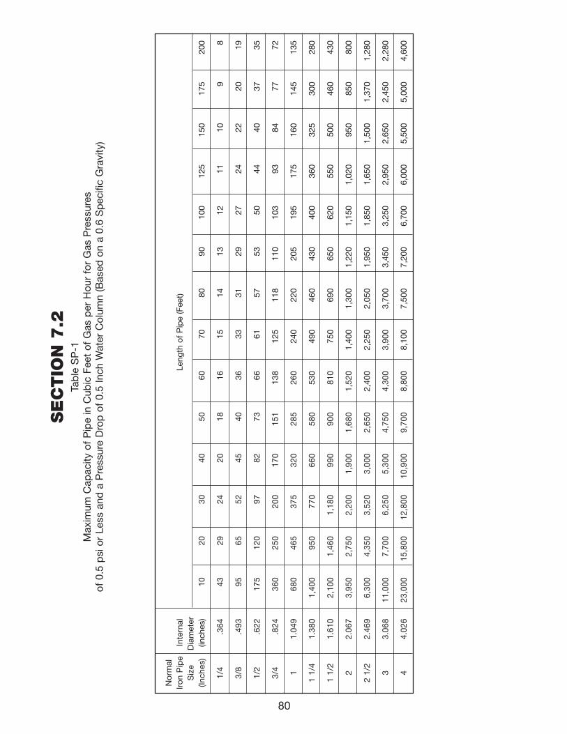
80
SE
CTIO
N 7
.2Ta
ble
SP
-1M
axim
um C
apac
ity o
f P
ipe
in C
ubic
Fee
t of
Gas
per
Hou
r fo
r G
as P
ress
ures
of
0.5
psi
or
Less
and
a P
ress
ure
Dro
p o
f 0.
5 In
ch W
ater
Col
umn
(Bas
ed o
n a
0.6
Sp
ecifi
c G
ravi
ty)
Nor
mal
Iron
Pip
eIn
tern
alLe
ngth
of
Pip
e (F
eet)
Siz
eD
iam
eter
(Inch
es)
(inch
es)
1020
3040
5060
7080
9010
012
515
017
520
0
1/4
.364
4329
2420
1816
1514
1312
1110
98
3/8
.493
9565
5245
4036
3331
2927
2422
2019
1/2
.622
175
120
9782
7366
6157
5350
4440
3735
3/4
.824
360
250
200
170
151
138
125
118
110
103
9384
7772
11.
049
680
465
375
320
285
260
240
220
205
195
175
160
145
135
1 1/
41.
380
1,40
095
077
066
058
053
049
046
043
040
036
032
530
028
0
1 1/
21.
610
2,10
01,
460
1,18
099
090
081
075
069
065
062
055
050
046
043
0
22.
067
3,95
02,
750
2,20
01,
900
1,68
01,
520
1,40
01,
300
1,22
01,
150
1,02
095
085
080
0
2 1/
22.
469
6,30
04,
350
3,52
03,
000
2,65
02,
400
2,25
02,
050
1,95
01,
850
1,65
01,
500
1,37
01,
280
33.
068
11,0
007,
700
6,25
05,
300
4,75
04,
300
3,90
03,
700
3,45
03,
250
2,95
02,
650
2,45
02,
280
44.
026
23,0
0015
,800
12,8
0010
,900
9,70
08,
800
8,10
07,
500
7,20
06,
700
6,00
05,
500
5,00
04,
600
111743_OmegaFlex_Txt:111743_OmegaFlex_Txt 5/28/09 11:57 AM Page 80
81
A.G.A. – American Gas Association
ANSI Z223.1 1988 – 1988 edition of the National FuelGas Code published by American NationalStandard Institute. Also known as NFPA 54(National Fire Protection Association).
Appliance (Equipment) – Any device which utilizesnatural gas or propane as a fuel or raw material toproduce light, heat, power, refrigeration or airconditioning.
Approved – Acceptable to the authorities havingjurisdiction.
Authority Having Jurisdiction – The organization,office or individual responsible for “approving”equipment, an installation or a procedure.
Btu – Abbreviation for British Thermal Unit, whichis the quantity of heat required to raise the tem-perature of one pound of water one degreeFahrenheit .
Cfh – Gas flow rate stated in cubic feet per hour.
Clothes Dryer – A device used to dry wet laundryby means of heat derived from the combustion ofnatural gases.
Design Pressure – The maximum operating pres-sure permitted by this document, as determinedby the design procedures applicable to the mate-rials involved.
Drip Leg – The container (dirt trap pocket) placedat a low point in a system of piping to collect for-eign material or condensate and from which itmay be removed.
EHD (Effective Hydraulic Diameter) – A relative mea-sure of Flow Capacity; This number is used tocompare individual sizes between different man-ufacturers. The higher the EHD number thegreater flow capacity of the piping.
Full Lockup – The capability of totally stopping theflow of gas if the load goes to zero, thus prevent-ing the downstream pressure from increasing
more than a certain upper limit pressure abovethe set point.
Header (manifold) – A pipe or fitting to which a num-ber of branch lines are connected.
ID – Inside diameter of pipe or tubing.
Inches (") W.C. – Method of stating pressure mea-sured in inches of water column by a manometeror pressure gauge. Commonly used in the gasindustry when the pressure is less than one (1)PSI.
1 PSI = 28 in. W.C. approximately
1/2 PSI = 14 in. W.C.
1/4 PSI = 7 in. W.C.
Load – The amount of gas in Cfh required by anappliance, or group of appliances, per their ratingplate.
L. P. Gas – Fuel gas that is stored and transportedin a liquid state, i.e., propane, butane, and mix-tures of these and other heavier hydrocarbons.
Meter – An instrument installed to measure thevolume of gas delivered through a piping system.
Manometer – A “U” shaped tube filled with water,or mercury where the pressure applied to one legof the “U” will push the liquid column a measur-able distance. Also known as a “U” gauge.
OD – Outside Diameter of pipe or tubing.
1/2 PSI – A shortened way of stating 1/2 poundsper square inch gauge. Also the name of a lowpressure piping system supplying gas from themeter at 1/2 PSI to each appliance pressure reg-ulator.
Piping – As used in this document, either pipe ortubing, or both. a. pipe – Rigid conduit of iron, steel, copper,
brass or aluminum.b. tubing – Semi rigid conduit of corrugated
stainless steel.
CHAPTER 8DEFINITION OF TERMINOLOGY
111743_OmegaFlex_Txt:111743_OmegaFlex_Txt 5/28/09 11:57 AM Page 81
82
Pressure – Unless otherwise stated, isexpressed in pounds per square inch aboveatmospheric pressure, i.e. gage pressure (PSI).
Pressure Drop – The loss in static pressure ofgas due to friction or obstruction in tubing,valves, fittings, regulators and burners.
Pressure Regulator – A valve which reducesand controls pressure. It automatically opensand closes in response to changing pressureconditions in the downstream piping.
PSI – Pounds per square inch gauge. Thepressure, as read from a measurement gageor device. Gauge pressure is pressure aboveatmospheric pressure.
Purge – To displace the original air, or gas, ora mixture of gas and air in a gas conduit witha new air/gas mixture.
Regulator, Appliance (inches w.c. – inches w.c.) – Adevice for controlling and maintaining a uni-form pressure to the manifold of gas burningequipment. This valve is typically part of theappliance. It reduces the pressure from 5.5"w.c. to the manifold pressure in the appli-ance. (approximately 3.5" w.c.).
Regulator, House Line (PSI – inches w.c.) – A deviceplaced in a gas line between the service regu-lator and the appliance regulator for control-ling, maintaining or reducing the pressure inthat portion of the piping system downstreamof the device. This valve reduces the houseline pressure (Typically 2 PSI) to the regulatormanifold pressure (Typically 8-10" w.c.).
Regulator, Service (PSI – PSI or inches w.c.) – Adevice installed by the serving gas supplier toreduce and limit the service line gas pressure.This valve reduces the service pressure to themetering pressure. It is located upstream ofthe gas meter.
Regulator Vent – The opening in the atmos-pheric side of the regulator housing permit-ting the in and out movement of air to com-pensate for the movement of the regulatordiaphragm.
Specific Gravity – As applied to gas, the ratio ofthe weight of a given volume to that of thesame volume of air, both measured under thesame conditions.
2 PSI – A shortened way of stating 2 poundsper square inch gauge pressure. Also thename of a piping system supplying gas at 2PSI to a house line regulator which thenreduces the pressure to inches W.C.upstream of the appliance regulator.
Valve, Manual Shut-off – A valve (located in thepiping system and readily accessible andoperable by the consumer) used to shut offindividual equipment.
Vent Limiter Device – Restriction/orifice typedevice in the vent outlet of a pressure regula-tor that controls or limits leakage, in the eventof a diaphragm leak. It also allows thediaphragm to move freely to control pressure.
111743_OmegaFlex_Txt:111743_OmegaFlex_Txt 5/28/09 11:57 AM Page 82
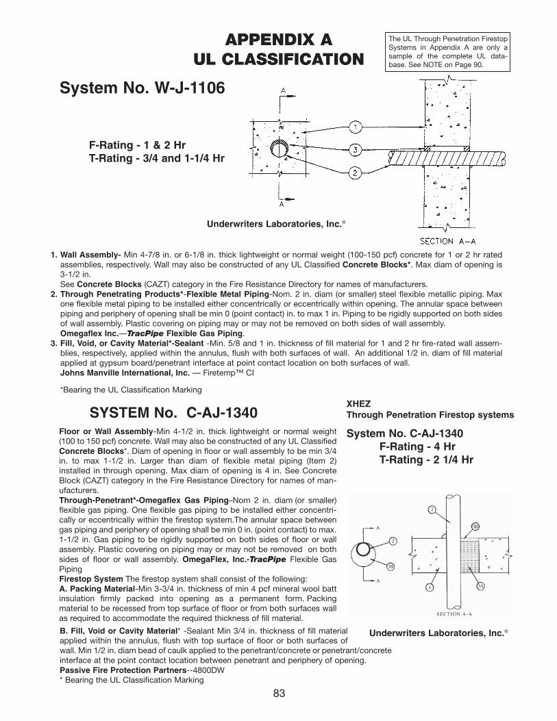
83
APPENDIX AUL CLASSIFICATION
SYSTEM No. C-AJ-1340Floor or Wall Assembly-Min 4-1/2 in. thick lightweight or normal weight(100 to 150 pcf) concrete. Wall may also be constructed of any UL ClassifiedConcrete Blocks*. Diam of opening in floor or wall assembly to be min 3/4in. to max 1-1/2 in. Larger than diam of flexible metal piping (Item 2)installed in through opening. Max diam of opening is 4 in. See ConcreteBlock (CAZT) category in the Fire Resistance Directory for names of man-ufacturers.Through-Penetrant*-Omegaflex Gas Piping–Nom 2 in. diam (or smaller)flexible gas piping. One flexible gas piping to be installed either concentri-cally or eccentrically within the firestop system.The annular space betweengas piping and periphery of opening shall be min 0 in. (point contact) to max.1-1/2 in. Gas piping to be rigidly supported on both sides of floor or wallassembly. Plastic covering on piping may or may not be removed on bothsides of floor or wall assembly. OmegaFlex, Inc.-TracPipe Flexible GasPipingFirestop System The firestop system shall consist of the following:A. Packing Material-Min 3-3/4 in. thickness of min 4 pcf mineral wool battinsulation firmly packed into opening as a permanent form. Packing material to be recessed from top surface of floor or from both surfaces wallas required to accommodate the required thickness of fill material.
B. Fill, Void or Cavity Material* -Sealant Min 3/4 in. thickness of fill materialapplied within the annulus, flush with top surface of floor or both surfaces ofwall. Min 1/2 in. diam bead of caulk applied to the penetrant/concrete or penetrant/concreteinterface at the point contact location between penetrant and periphery of opening.Passive Fire Protection Partners--4800DW* Bearing the UL Classification Marking
Underwriters Laboratories, Inc.®
XHEZThrough Penetration Firestop systems
System No. C-AJ-1340F-Rating - 4 HrT-Rating - 2 1/4 Hr
F-Rating - 1 & 2 HrT-Rating - 3/4 and 1-1/4 Hr
1. Wall Assembly- Min 4-7/8 in. or 6-1/8 in. thick lightweight or normal weight (100-150 pcf) concrete for 1 or 2 hr ratedassemblies, respectively. Wall may also be constructed of any UL Classified Concrete Blocks*. Max diam of opening is3-1/2 in.See Concrete Blocks (CAZT) category in the Fire Resistance Directory for names of manufacturers.
2. Through Penetrating Products*-Flexible Metal Piping-Nom. 2 in. diam (or smaller) steel flexible metallic piping. Maxone flexible metal piping to be installed either concentrically or eccentrically within opening. The annular space betweenpiping and periphery of opening shall be min 0 (point contact) in. to max 1 in. Piping to be rigidly supported on both sidesof wall assembly. Plastic covering on piping may or may not be removed on both sides of wall assembly.Omegaflex Inc.—TracPipe Flexible Gas Piping.
3. Fill, Void, or Cavity Material*-Sealant -Min. 5/8 and 1 in. thickness of fill material for 1 and 2 hr fire-rated wall assem -blies, respectively, applied within the annulus, flush with both surfaces of wall. An additional 1/2 in. diam of fill materialapplied at gypsum board/penetrant interface at point contact location on both surfaces of wall.Johns Manville International, Inc. — Firetemp™ CI
*Bearing the UL Classification Marking
Underwriters Laboratories, Inc.®
The UL Through Penetration FirestopSystems in Appendix A are only asample of the complete UL data-base. See NOTE on Page 90.
System No. W-J-1106
111743_OmegaFlex_Txt:111743_OmegaFlex_Txt 5/28/09 11:57 AM Page 83
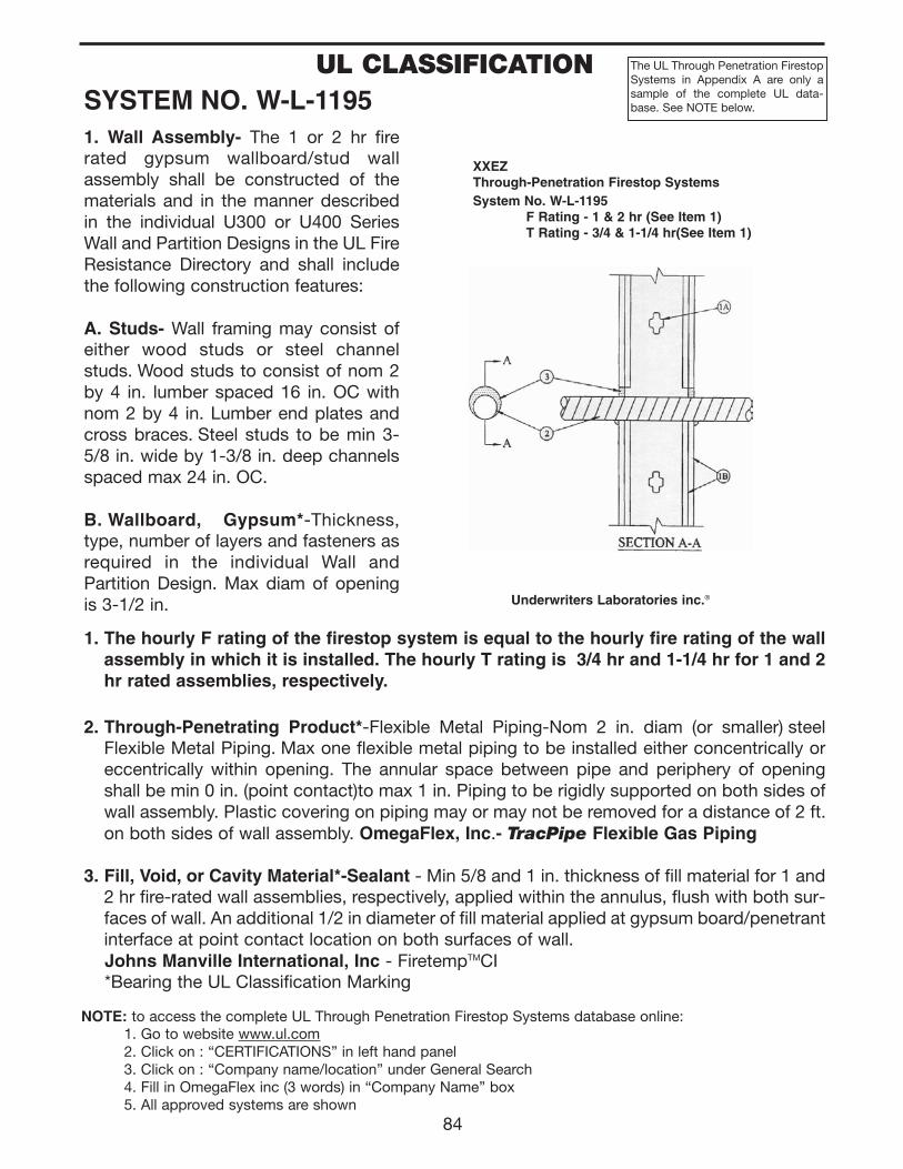
84
SYSTEM NO. W-L-11951. Wall Assembly- The 1 or 2 hr firerated gypsum wallboard/stud wallassembly shall be constructed of thematerials and in the manner describedin the individual U300 or U400 SeriesWall and Partition Designs in the UL FireResistance Directory and shall includethe following construction features:
A. Studs- Wall framing may consist ofeither wood studs or steel channelstuds. Wood studs to consist of nom 2by 4 in. lumber spaced 16 in. OC withnom 2 by 4 in. Lumber end plates andcross braces. Steel studs to be min 3-5/8 in. wide by 1-3/8 in. deep channelsspaced max 24 in. OC.
B. Wallboard, Gypsum*-Thickness,type, number of layers and fasteners asrequired in the individual Wall andPartition Design. Max diam of openingis 3-1/2 in.
XXEZThrough-Penetration Firestop Systems
Underwriters Laboratories inc.®
System No. W-L-1195F Rating - 1 & 2 hr (See Item 1)T Rating - 3/4 & 1-1/4 hr(See Item 1)
1. The hourly F rating of the firestop system is equal to the hourly fire rating of the wallassembly in which it is installed. The hourly T rating is 3/4 hr and 1-1/4 hr for 1 and 2hr rated assemblies, respectively.
2. Through-Penetrating Product*-Flexible Metal Piping-Nom 2 in. diam (or smaller) steelFlexible Metal Piping. Max one flexible metal piping to be installed either concentrically oreccentrically within opening. The annular space between pipe and periphery of openingshall be min 0 in. (point contact)to max 1 in. Piping to be rigidly supported on both sides ofwall assembly. Plastic covering on piping may or may not be removed for a distance of 2 ft.on both sides of wall assembly. OmegaFlex, Inc.- TracPipe Flexible Gas Piping
3. Fill, Void, or Cavity Material*-Sealant - Min 5/8 and 1 in. thickness of fill material for 1 and2 hr fire-rated wall assemblies, respectively, applied within the annulus, flush with both sur-faces of wall. An additional 1/2 in diameter of fill material applied at gypsum board/penetrantinterface at point contact location on both surfaces of wall.Johns Manville International, Inc - FiretempTMCI*Bearing the UL Classification Marking
UL CLASSIFICATION The UL Through Penetration FirestopSystems in Appendix A are only asample of the complete UL data-base. See NOTE below.
NOTE: to access the complete UL Through Penetration Firestop Systems database online:1. Go to website www.ul.com2. Click on : “CERTIFICATIONS” in left hand panel3. Click on : “Company name/location” under General Search4. Fill in OmegaFlex inc (3 words) in “Company Name” box5. All approved systems are shown
111743_OmegaFlex_Txt:111743_OmegaFlex_Txt 5/28/09 11:57 AM Page 84
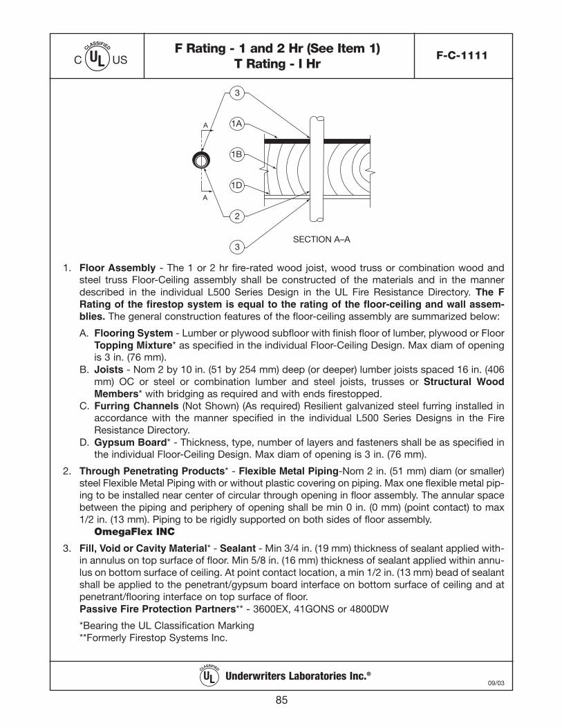
A
A
SECTION A–A
3
2
3
1A
1B
1D
85
F Rating - 1 and 2 Hr (See Item 1)T Rating - I Hr
F-C-1111
CLASSIFIED
ULC US
1. Floor Assembly - The 1 or 2 hr fire-rated wood joist, wood truss or combination wood andsteel truss Floor-Ceiling assembly shall be constructed of the materials and in the mannerdescribed in the individual L500 Series Design in the UL Fire Resistance Directory. The FRating of the firestop system is equal to the rating of the floor-ceiling and wall assem-blies. The general construction features of the floor-ceiling assembly are summarized below:
A. Flooring System - Lumber or plywood subfloor with finish floor of lumber, plywood or FloorTopping Mixture* as specified in the individual Floor-Ceiling Design. Max diam of openingis 3 in. (76 mm).
B. Joists - Nom 2 by 10 in. (51 by 254 mm) deep (or deeper) lumber joists spaced 16 in. (406mm) OC or steel or combination lumber and steel joists, trusses or Structural WoodMembers* with bridging as required and with ends firestopped.
C. Furring Channels (Not Shown) (As required) Resilient galvanized steel furring installed inaccordance with the manner specified in the individual L500 Series Designs in the FireResistance Directory.
D. Gypsum Board* - Thickness, type, number of layers and fasteners shall be as specified inthe individual Floor-Ceiling Design. Max diam of opening is 3 in. (76 mm).
2. Through Penetrating Products* - Flexible Metal Piping-Nom 2 in. (51 mm) diam (or smaller)steel Flexible Metal Piping with or without plastic covering on piping. Max one flexible metal pip-ing to be installed near center of circular through opening in floor assembly. The annular spacebetween the piping and periphery of opening shall be min 0 in. (0 mm) (point contact) to max1/2 in. (13 mm). Piping to be rigidly supported on both sides of floor assembly.
OmegaFlex INC
3. Fill, Void or Cavity Material* - Sealant - Min 3/4 in. (19 mm) thickness of sealant applied with-in annulus on top surface of floor. Min 5/8 in. (16 mm) thickness of sealant applied within annu-lus on bottom surface of ceiling. At point contact location, a min 1/2 in. (13 mm) bead of sealantshall be applied to the penetrant/gypsum board interface on bottom surface of ceiling and atpenetrant/flooring interface on top surface of floor.Passive Fire Protection Partners** - 3600EX, 41GONS or 4800DW
*Bearing the UL Classification Marking **Formerly Firestop Systems Inc.
CLASSIFIED
UL 09/03Underwriters Laboratories Inc.®
111743_OmegaFlex_Txt:111743_OmegaFlex_Txt 5/28/09 11:57 AM Page 85
86
APPENDIX BMANUFACTURED HOUSING GUIDELINES
A. CODE AND ADMINISTRATIVE REQUIREMENTS
1. Manufactured homes and mobile homes bearing an insignia or required to bear aninsignia must comply with Title VI 24 Code of Federal Regulations, The NationalManufactured Housing Act of 1974 Part 3280. In most jurisdictions this requirementremains in force when the structural, electrical plumbing or mechanical systems arealtered. The Code of Federal Regulations, Housing and Urban Development, Part 3280Manufactured Home Construction and Safety Standards is applicable throughout theUSA for manufactured housing construction (also known as “HUD code” housing).
2. There are other types of factory-built housing that do not fall directly under theclassification “HUD code” which must also be reviewed for special installationconsiderations when designing a CSST gas piping system or appliance retrofit. Someexamples of this type of housing are Assembly Buildings, Panelized, Modular, andProduction Build. TracPipe should not be considered for RVs, which are subject toover the road use and not just initial placement or repositioning.
3. Part 3280 Manufactured Home Construction and Safety Standards 1994 has not beenrevised or updated for several years. There has been an effort by both NFPA andCABO (now a part of the ICC) to have the US Congress adopt a new ManufacturedHousing Code. The latest version of the CABO Code ICC/ANSI 2.0 ManufacturedHousing Construction Safety Standards is available but has not been adopted byCongress.
4. Omegaflex has obtained a written opinion from the U.S. Department of Housing andUrban Development regarding the use of TracPipe CSST. This HUD decision states“CSST, such as TracPipe, is allowed to be used in HUD manufactured homes (basedupon incorporation of NFPA 54-1992 ANSI 223.1 The National Fuel Gas Code intoSection 3280.703 Minimum Standards).” This opinion shall be confirmed with Stateauthorities responsible for inspections of HUD Code buildings prior to installingTracPipe after the home has left the factory. For factory installations, approval by theDAPIA (Manufacturer’s Design Approval Primary Inspection Agency) is normallyrequired for the piping system design. Contact Omegaflex for specification data and acopy of the HUD decision letter.
B. PIPING SYSTEM DESIGN REQUIREMENTS
1. The primary information for any TracPipe installation is contained in the TracPipeDesign Guide and Installation Instructions (latest edition). This guide providesmanufacturer’s instructions that are a requirement of the ANSI/CSA LC-1 Standardgoverning certification and test requirements for Corrugated Stainless Steel Tubing.Manufacturer’s instructions must be followed.
111743_OmegaFlex_Txt:111743_OmegaFlex_Txt 5/28/09 11:57 AM Page 86
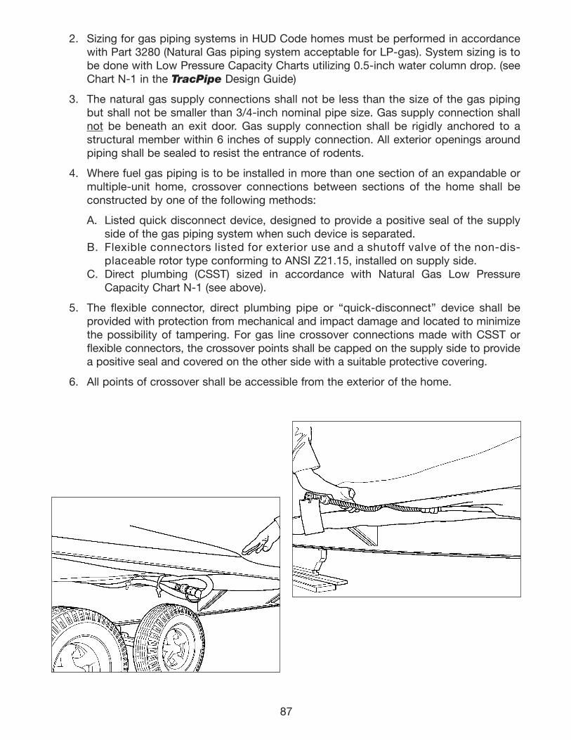
87
2. Sizing for gas piping systems in HUD Code homes must be performed in accordancewith Part 3280 (Natural Gas piping system acceptable for LP-gas). System sizing is tobe done with Low Pressure Capacity Charts utilizing 0.5-inch water column drop. (seeChart N-1 in the TracPipe Design Guide)
3. The natural gas supply connections shall not be less than the size of the gas pipingbut shall not be smaller than 3/4-inch nominal pipe size. Gas supply connection shallnot be beneath an exit door. Gas supply connection shall be rigidly anchored to astructural member within 6 inches of supply connection. All exterior openings aroundpiping shall be sealed to resist the entrance of rodents.
4. Where fuel gas piping is to be installed in more than one section of an expandable ormultiple-unit home, crossover connections between sections of the home shall beconstructed by one of the following methods:
A. Listed quick disconnect device, designed to provide a positive seal of the supplyside of the gas piping system when such device is separated.
B. Flexible connectors listed for exterior use and a shutoff valve of the non-dis-placeable rotor type conforming to ANSI Z21.15, installed on supply side.
C. Direct plumbing (CSST) sized in accordance with Natural Gas Low PressureCapacity Chart N-1 (see above).
5. The flexible connector, direct plumbing pipe or “quick-disconnect” device shall beprovided with protection from mechanical and impact damage and located to minimizethe possibility of tampering. For gas line crossover connections made with CSST orflexible connectors, the crossover points shall be capped on the supply side to providea positive seal and covered on the other side with a suitable protective covering.
6. All points of crossover shall be accessible from the exterior of the home.
111743_OmegaFlex_Txt:111743_OmegaFlex_Txt 5/28/09 11:57 AM Page 87
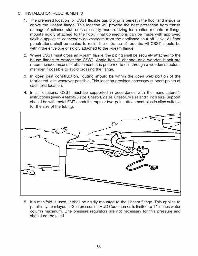
88
C. INSTALLATION REQUIREMENTS
1. The preferred location for CSST flexible gas piping is beneath the floor and inside orabove the I-beam flange. This location will provide the best protection from transitdamage. Appliance stub-outs are easily made utilizing termination mounts or flangemounts rigidly attached to the floor. Final connections can be made with approvedflexible appliance connectors downstream from the appliance shut-off valve. All floorpenetrations shall be sealed to resist the entrance of rodents. All CSST should bewithin the envelope or rigidly attached to the I-beam flange.
2. Where CSST must cross an I-beam flange, the piping shall be securely attached to thehouse flange to protect the CSST. Angle iron, C-channel or a wooden block arerecommended means of attachment. It is preferred to drill through a wooden structuralmember if possible to avoid crossing the flange.
3. In open joist construction, routing should be within the open web portion of thefabricated joist wherever possible. This location provides necessary support points ateach joist location.
4. In all locations, CSST must be supported in accordance with the manufacturer’sinstructions (every 4 feet-3/8 size, 6 feet-1/2 size, 8 feet-3/4 size and 1 inch size) Supportshould be with metal EMT conduit straps or two-point attachment plastic clips suitablefor the size of the tubing.
5. If a manifold is used, it shall be rigidly mounted to the I-beam flange. This applies toparallel system layouts. Gas pressure in HUD Code homes is limited to 14 inches watercolumn maximum. Line pressure regulators are not necessary for this pressure andshould not be used.
111743_OmegaFlex_Txt:111743_OmegaFlex_Txt 5/28/09 11:57 AM Page 88

89
6. The gas piping shall be bonded to the frame of the home by the use of:
a. Solderless type grounding terminal with a star washer bolted to the chassis;b. Grounding clamp attached to a gas piping fitting. (For attachment of clamp to
TracPipe fitting, refer to Section 4.10 – Electrical Bonding/Grounding. Do not clampto the stainless steel portion under any circumstances.); and
c. Bonding electrode conductor sizing shall be in accordance with NFPA 70 Article 250Section and Table 250-66.
7. Concealed tubing: CSST shall not be run inside walls, partitions or roofs. Where tubingpasses through walls, floors, partitions, roofs, or similar installations, such tubing shallbe protected by the use of weather resistant grommets that shall snugly fit both the tub-ing and the hole through which the tubing passes. DO NOT remove the yellow poly-ethylene jacket in any penetrations.
8. All CSST tubing joints shall have any exposed sections of stainless steel pipingwrapped with silicone self-bonding tape. The under-floor portion of the manufacturedhome is considered an outdoor location. Proper support (per item 4 above) is requiredunder the floor.
9. Retrofit of appliances:
a. The gas supply connection shall be rigidly anchored to a structural member within6 inches of supply connection.
b. CSST shall be supported and protected per manufacturer’s instructions. (See items4 and 7 above.)
c. Pressure test gas piping per Item D 1 below before operating appliance.
D. INSPECTION AND TEST REQUIREMENTS
1. Pressure test in accordance with Part 3280.705k (8) testing for leakage (8 i) beforeappliances are connected and (8 ii) after appliances are connected.
111743_OmegaFlex_Txt:111743_OmegaFlex_Txt 5/28/09 11:57 AM Page 89
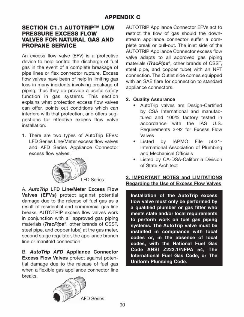
90
SECTION C1.1 AUTOTRIP™ LOWPRESSURE EXCESS FLOWVALVES FOR NATURAL GAS ANDPROPANE SERVICE
An excess flow valve (EFV) is a protectivedevice to help control the discharge of fuelgas in the event of a complete breakage ofpipe lines or flex connector rupture. E xcessflow valves have been of help in limiting gasloss in many incidents involving breakage ofpiping; thus they do provide a useful safetyfunction in gas systems. This sectionexplains what protection excess flow valvescan offer, points out conditions which caninterfere with that protection, and offers sug-gestions for effective excess flow valveinstallation.
1. There are two types of AutoTrip EFVs:LFD Series Line/Meter excess flow valvesand AFD Series Appliance Connectorexcess flow valves.
A. AutoTrip LFD Line/Meter Excess FlowValves (EFVs) protect against potentialdamage due to the release of fuel gas as aresult of residential and commercial gas linebreaks. AUTOTRIP excess flow valves workin conjunction with all approved gas pipingmaterials (TracPipe®, other brands of CSST,steel pipe, and copper tube) at the gas meter,second stage regulator, the appliance branchline or manifold connection.
B. AutoTrip AFD Appliance ConnectorExcess Flow Valves protect against poten-tial damage due to the release of fuel gaswhen a flexible gas appliance connector linebreaks.
AUTOTRIP Appliance Connector EFVs act torestrict the flow of gas should the down-stream appliance connector suffer a com-plete break or pull-out. The inlet side of theAUTOTRIP Appliance Connector excess flowvalve adapts to all approved gas pipingmaterials (TracPipe®, other brands of CSST,steel pipe, and copper tube) with an NPTconnection. The Outlet side comes equippedwith an SAE flare for connection to standardappliance connectors.
2. Quality Assurance• AutoTrip valves are Design-Certified
by CSA International and manufac-tured and 100% factory tested inaccordance with the IAS U.S.Requirements 3-92 for Excess FlowValves
• Listed by IAPMO File 5031-International Association of Plumbingand Mechanical Officials
• Listed by CA-DSA-California Divisionof State Architect
3. IMPORTANT NOTES and LIMITATIONSRegarding the Use of Excess Flow Valves
Installation of the AutoTrip excessflow valve must only be performed bya qualified plumber or gas fitter whomeets state and/or local requirementsto perform work on fuel gas pipingsystems. The AutoTrip valve must beinstalled in compliance with localcodes or, in the absence of localcodes, with the National Fuel GasCode ANSI Z223.1/NFPA 54, TheInternational Fuel Gas Code, or TheUniform Plumbing Code.
LFD Series
APPENDIX C
AFD Series
111743_OmegaFlex_Txt:111743_OmegaFlex_Txt 5/28/09 11:57 AM Page 90
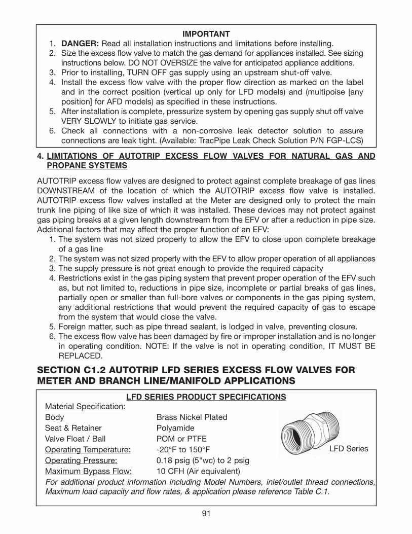
91
IMPORTANT1. DANGER: Read all installation instructions and limitations before installing.2. Size the excess flow valve to match the gas demand for appliances installed. See sizing
instructions below. DO NOT OVERSIZE the valve for anticipated appliance additions.3. Prior to installing, TURN OFF gas supply using an upstream shut-off valve.4. Install the excess flow valve with the proper flow direction as marked on the label
and in the correct position (vertical up only for LFD models) and (multipoise [anyposition] for AFD models) as specified in these instructions.
5. After installation is complete, pressurize system by opening gas supply shut off valveVERY SLOWLY to initiate gas service.
6. Check all connections with a non-corrosive leak detector solution to assure connections are leak tight. (Available: TracPipe Leak Check Solution P/N FGP-LCS)
SECTION C1.2 AUTOTRIP LFD SERIES EXCESS FLOW VALVES FORMETER AND BRANCH LINE/MANIFOLD APPLICATIONS
LFD SERIES PRODUCT SPECIFICATIONSMaterial Specification:Body Brass Nickel PlatedSeat & Retainer PolyamideValve Float / Ball POM or PTFEOperating Temperature: -20°F to 150°FOperating Pressure: 0.18 psig (5"wc) to 2 psigMaximum Bypass Flow: 10 CFH (Air equivalent) For additional product information including Model Numbers, inlet/outlet thread connections,Maximum load capacity and flow rates, & application please reference Table C.1.
4. LIMITATIONS OF AUTOTRIP EXCESS FLOW VALVES FOR NATURAL GAS ANDPROPANE SYSTEMS
AUTOTRIP excess flow valves are designed to protect against complete breakage of gas linesDOWNSTREAM of the location of which the AUTOTRIP excess flow valve is installed.AUTOTRIP excess flow valves installed at the Meter are designed only to protect the maintrunk line piping of like size of which it was installed. These devices may not protect againstgas piping breaks at a given length downstream from the EFV or after a reduction in pipe size.Additional factors that may affect the proper function of an EFV:
1. The system was not sized properly to allow the EFV to close upon complete breakageof a gas line
2. The system was not sized properly with the EFV to allow proper operation of all appliances3. The supply pressure is not great enough to provide the required capacity 4. Restrictions exist in the gas piping system that prevent proper operation of the EFV such
as, but not limited to, reductions in pipe size, incomplete or partial breaks of gas lines,partially open or smaller than full-bore valves or components in the gas piping system,any additional restrictions that would prevent the required capacity of gas to escapefrom the system that would close the valve.
5. Foreign matter, such as pipe thread sealant, is lodged in valve, preventing closure.6. The excess flow valve has been damaged by fire or improper installation and is no longer
in operating condition. NOTE: If the valve is not in operating condition, IT MUST BEREPLACED.
LFD Series
111743_OmegaFlex_Txt:111743_OmegaFlex_Txt 5/28/09 11:57 AM Page 91
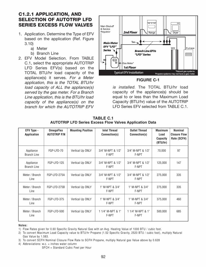
92
C1.2.1 APPLICATION, AND SELECTION OF AUTOTRIP LFDSERIES EXCESS FLOW VALVES
1. Application. Determine the Type of EFVbased on the application (Ref. Figure3.10)
a) Meterb) Branch Line
2. EFV Model Selection. From TABLEC.1, select the appropriate AUTOTRIPLFD Series EFV(s) based on theTOTAL BTU/hr load capacity of theappliance(s) it serves. For a Meterapplication, this is the TOTAL BTU/hrload capacity of ALL the appliance(s)served by the gas meter. For a BranchLine application, this is the BTU/hr loadcapacity of the appliance(s) on thebranch for which the AUTOTRIP EFV
is installed. The TOTAL BTU/hr loadcapacity of the appliance(s) should beequal to or less than the Maximum LoadCapacity (BTU/hr) value of the AUTOTRIPLFD Series EFV selected from TABLE C.1.
FIGURE C-1
TABLE C.1AUTOTRIP LFD Series Excess Flow Valves Application Data
EFV Type - OmegaFlex Mounting Position Inlet Thread Outlet Thread Maximum NominalApplication AUTOTRIP P/N Connection(s) Connection(s) Load Closure Flow
Capacity Rate (SCFH)(BTU/hr)
Appliance FGP-LFD-70 Vertical Up ONLY 3/4" M-NPT & 1/2" 3/4" M-NPT & 1/2" 70,000 97Branch Line F-NPT F-NPT
Appliance FGP-LFD-125 Vertical Up ONLY 3/4" M-NPT & 1/2" 3/4" M-NPT & 1/2" 125,000 147Branch Line F-NPT F-NPT
Meter / Branch FGP-LFD-275A Vertical Up ONLY 3/4" M-NPT & 1/2" 3/4" M-NPT & 1/2" 275,000 335Line F-NPT F-NPT
Meter / Branch FGP-LFD-275B Vertical Up ONLY 1" M-NPT & 3/4" 1" M-NPT & 3/4" 275,000 335Line F-NPT F-NPT
Meter / Branch FGP-LFD-375 Vertical Up ONLY 1" M-NPT & 3/4" 1" M-NPT & 3/4" 375,000 460Line F-NPT F-NPT
Meter / Branch FGP-LFD-500 Vertical Up ONLY 1 1/4" M-NPT & 1" 1 1/4" M-NPT & 1" 500,000 685Line F-NPT F-NPT
Notes:1) Flow Rates given for 0.60 Specific Gravity Natural Gas with an Avg. Heating Value of 1000 BTU / cubic foot.2) To convert Maximum Load Capacity value to BTU/hr Propane (1.52 Specific Gravity, 2520 BTU / cubic foot), multiply Natural
Gas Value by 1.583.3) To convert SCFH Nominal Closure Flow Rate to SCFH Propane, multiply Natural gas Value above by 0.6284) Abbreviations: w.c. = inches water column
SFCH = Standard Cubic Feet per Hour
111743_OmegaFlex_Txt:111743_OmegaFlex_Txt 5/28/09 11:57 AM Page 92
93
C1.2.2 GAS PIPING SYSTEMSIZING WITH LFD SERIESEXCESS FLOW VALVES
AUTOTRIP LFD Series excess flow valvesmust be sized properly for the gas pipingsystem in which they are installed. Wheninstalling AUTOTRIP excess flow valves with-in a fuel gas piping system, the user mustassure that:
1. The AUTOTRIP LFD Series EFV will closeupon a complete breakage or rupture ofgas piping at an expected length down-stream of the EFV. It is recommendedthat the installer conduct tests on the gaspiping system to ensure the EFV(s) willfunction as intended. Note: Tests shouldbe performed in accordance with allapplicable local and national codes.
2. The addition of the AUTOTRIP LFD SeriesEFV will allow all appliances to which theEFV serves to operate properly withoutthe undue loss of pressure. It is recom-mended that the installer run all appliances with the EFV(s) installed toassure proper operation.
C1.2.3 METHODS OF SIZING
STANDARD SIZING METHOD - When sizinga gas piping system including AutoTrip LFDSeries EFVs, size the gas piping systemusing the following Tables (N-1AT, N-3AT, N-5AT, SP-1AT, P-1AT) using standard meth-ods of gas pipe sizing – Branch Length orLongest Run Method.
ALTERNATE SIZING METHOD – If using anEngineered Method, i.e. “Sum of PressuresMethod” of gas pipe sizing, use the pressuredrop values in Figure C-3 in your gas pipingcalculations.
C1.2.4 SIZING INSTRUCTIONSFOR AUTOTRIP LFD SERIES EFVSUSED WITH TRACPIPE CSSTSYSTEMS
A. Meter Applications (LFD Series LFD-275A, LFD-275B, LFD-375, LFD-500)
1. Choose the appropriate AutoTrip LFDSeries Meter EFV using TABLE C.1based on the total capacity of the gaspiping system served by that meter.
2. Using the appropriate AutoTripCapacity Chart “Table N-1AT AutoTripLow Pressure” or “Table N-5ATAutoTrip (2-psi system)” based uponsystem pressure; determine the size ofCSST based on the AutoTrip EFVselected in Step 1 and the appropriatesizing length. This size of CSST isdesigned to allow the AutoTrip EFV toact as a safety shut-off valve in theevent of a complete breakage of themain trunk line piping.
B Branch Line / Manifold Applications (LFDSeries LFD-70, LFD-125, LFD-275A, LFD-275B, LFD-375, and LFD-500 )
1. Elevated Pressure 2 PSI system(Manifold with parallel arrangement)a.Choose the appropriate size
AutoTrip LFD Series ApplianceBranch Line EFV using TABLE 3.1based on the capacity for eachmanifold outlet. Select an EFV withsufficient capacity to supply theappliance(s) connected to the outlet.
b.Using AutoTrip Capacity Chart“Table N-3AT AutoTrip Dual PressureSystem” determine size of TracPipeCSST based on the AutoTrip EFVselected in Step a and the appropri-ate sizing length from the manifold tothe appliance(s). This size of CSST isdesigned to allow the AutoTrip EFVto act as a safety shut-off valve inthe event of the complete breakageof the downstream branch pipe lineor flex connector rupture.
111743_OmegaFlex_Txt:111743_OmegaFlex_Txt 5/28/09 11:57 AM Page 93
94
2. Series System Low Pressurea.When there is no manifold, the EFV
should be located at the tee or fittingwhere the appliance drop attachesto the trunk line. If this is a concealedlocation, follow local codes.
b.Choose the appropriate sizeAutoTrip LFD Series ApplianceBranch Line EFV using TABLE C.1based on the capacity for thatbranch line. Select an EFV with sufficient capacity to supply theappliance(s) connected to that drop.
c.Using AutoTrip Capacity Chart“Table N-1AT AutoTrip LowPressure” determine size ofTracPipe CSST based on theAutoTrip EFV selected in Step b andthe appropriate sizing length fromthe appliance back to the meter.This size of CSST is designed toallow the AutoTrip EFV to act as asafety shut-off valve in the event ofa complete breakage of the down-stream branch pipe line or flex connector rupture.
C1.2.5 SIZING INSTRUCTIONSFOR AUTOTRIP LFD SERIES EFVSUSED WITH LOW PRESSURESTEEL PIPE SYSTEMS
1. Choose the AutoTrip LFD Series EFV(Appliance branch line or Meter) usingTABLE C.1 which will supply the neces-sary capacity of the meter or appliance(s)it serves.
2. Using AutoTrip Capacity Chart “Table SP-1AT AutoTrip Steel Pipe Low Pressure”determine the size of steel pipe based onthe AutoTrip EFV selected in Step 1 and theappropriate sizing length. This size of steelpipe is designed to allow the AutoTrip EFVto act as a safety shut-off valve in the eventof a complete breakage of the main trunkline piping (Meter EFV) or of the down-stream branch pipe line or flex connectorrupture (Appliance Branch Line EFV).
C1.2.6 LFD INSTALLATIONINSTRUCTIONS
A. Installation of AUTOTRIP LFD Series MeterApplication excess flow valves down-stream of the Gas Meter Outlet
The AUTOTRIP device can be installeddownstream of the gas company meterand bypass tee outlet using standard pipefittings and procedures. AUTOTRIP MeterValves-LFD models must be installed with-in 5 degrees of the vertical position with theflow arrow pointing upward in the directionof flow. Note: EFVs installed at the Meterare designed only to protect the main trunkline of like pipe size downstream of the EFV.
B. Installation of AUTOTRIP LFD SeriesBranch Line excess flow valves at the Teeor Manifold connection of a Branch Lineto an Appliance
AUTOTRIP Branch Line excess flow valvesshould be connected directly to the man -ifold outlet at the point between the mani-fold and the gas appliance lines. If there isno manifold, the valves could be located atthe tee or fitting where the appliance dropattaches to the trunk line. AUTOTRIPBranch Line excess flow valves must beinstalled in the vertical position (within 5degrees) with the flow arrow pointingupward in the direction of flow.
C. Step-by-Step Installation Instructions1. Prior to installing the AUTOTRIP
excess flow valve (EFV), turn gas sup-ply off upstream of the EFV usingappropriate shut-off valve. For aMeter EFV installation, this will be themain gas company shut-off valve.
2. Install AUTOTRIP EFV into piping system at desired location usingappropriate pipe fittings and tools.When using a thread sealant on pipethreads, do not allow the sealant,Teflon tape or any debris to enter thevalve. Foreign matter can lodge in thevalve and prevent proper operation.
111743_OmegaFlex_Txt:111743_OmegaFlex_Txt 5/28/09 11:57 AM Page 94
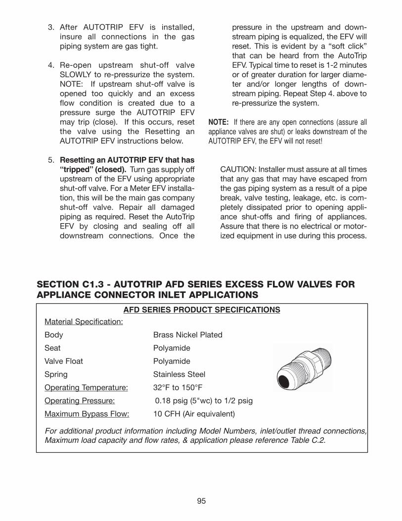
95
3. After AUTOTRIP EFV is installed,insure all connections in the gas piping system are gas tight.
4. Re-open upstream shut-off valveSLOWLY to re-pressurize the system.NOTE: If upstream shut-off valve isopened too quickly and an excessflow condition is created due to apressure surge the AUTOTRIP EFVmay trip (close). If this occurs, resetthe valve using the Resetting anAUTOTRIP EFV instructions below.
5. Resetting an AUTOTRIP EFV that has“tripped” (closed). Turn gas supply offupstream of the EFV using appropriateshut-off valve. For a Meter EFV installa-tion, this will be the main gas companyshut-off valve. Repair all damaged piping as required. Reset the AutoTripEFV by closing and sealing off alldownstream connections. Once the
pressure in the upstream and down-stream piping is equalized, the EFV willreset. This is evident by a “soft click”that can be heard from the AutoTripEFV. Typical time to reset is 1-2 minutesor of greater duration for larger diame-ter and/or longer lengths of down-stream piping. Repeat Step 4. above tore-pressurize the system.
NOTE: If there are any open connections (assure allappliance valves are shut) or leaks downstream of theAUTOTRIP EFV, the EFV will not reset!
CAUTION: Installer must assure at all timesthat any gas that may have escaped fromthe gas piping system as a result of a pipebreak, valve testing, leakage, etc. is com-pletely dissipated prior to opening appli-ance shut-offs and firing of appliances.Assure that there is no electrical or motor-ized equipment in use during this process.
SECTION C1.3 - AUTOTRIP AFD SERIES EXCESS FLOW VALVES FORAPPLIANCE CONNECTOR INLET APPLICATIONS
AFD SERIES PRODUCT SPECIFICATIONS
Material Specification:
Body Brass Nickel Plated
Seat Polyamide
Valve Float Polyamide
Spring Stainless Steel
Operating Temperature: 32°F to 150°F
Operating Pressure: 0.18 psig (5"wc) to 1/2 psig
Maximum Bypass Flow: 10 CFH (Air equivalent)
For additional product information including Model Numbers, inlet/outlet thread connections,Maximum load capacity and flow rates, & application please reference Table C.2.
111743_OmegaFlex_Txt:111743_OmegaFlex_Txt 5/28/09 11:57 AM Page 95
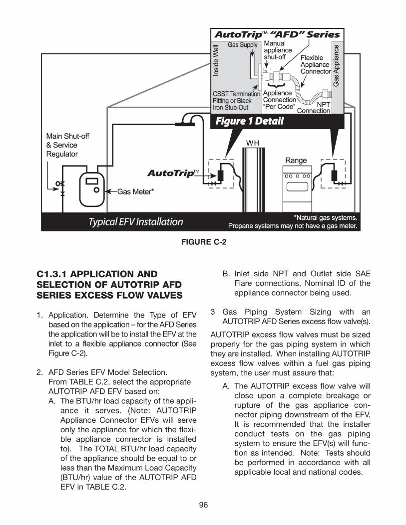
96
FIGURE C-2
C1.3.1 APPLICATION AND SELECTION OF AUTOTRIP AFDSERIES EXCESS FLOW VALVES
1. Application. Determine the Type of EFVbased on the application – for the AFD Seriesthe application will be to install the EFV at theinlet to a flexible appliance connector (SeeFigure C-2).
2. AFD Series EFV Model Selection. From TABLE C.2, select the appropriate AUTOTRIP AFD EFV based on:A. The BTU/hr load capacity of the appli-
ance it serves. (Note: AUTOTRIPAppliance Connector EFVs will serveonly the appliance for which the flexi-ble appliance connector is installedto). The TOTAL BTU/hr load capacityof the appliance should be equal to orless than the Maximum Load Capacity(BTU/hr) value of the AUTOTRIP AFDEFV in TABLE C.2.
B. Inlet side NPT and Outlet side SAEFlare connections, Nominal ID of theappliance connector being used.
3 Gas Piping System Sizing with anAUTOTRIP AFD Series excess flow valve(s).
AUTOTRIP excess flow valves must be sizedproperly for the gas piping system in whichthey are installed. When installing AUTOTRIPexcess flow valves within a fuel gas pipingsystem, the user must assure that:
A. The AUTOTRIP excess flow valve willclose upon a complete breakage orrupture of the gas appliance con -nector piping downstream of the EFV.It is recommended that the installerconduct tests on the gas piping system to ensure the EFV(s) will func-tion as intended. Note: Tests shouldbe performed in accordance with allapplicable local and national codes.
111743_OmegaFlex_Txt:111743_OmegaFlex_Txt 5/28/09 11:57 AM Page 96
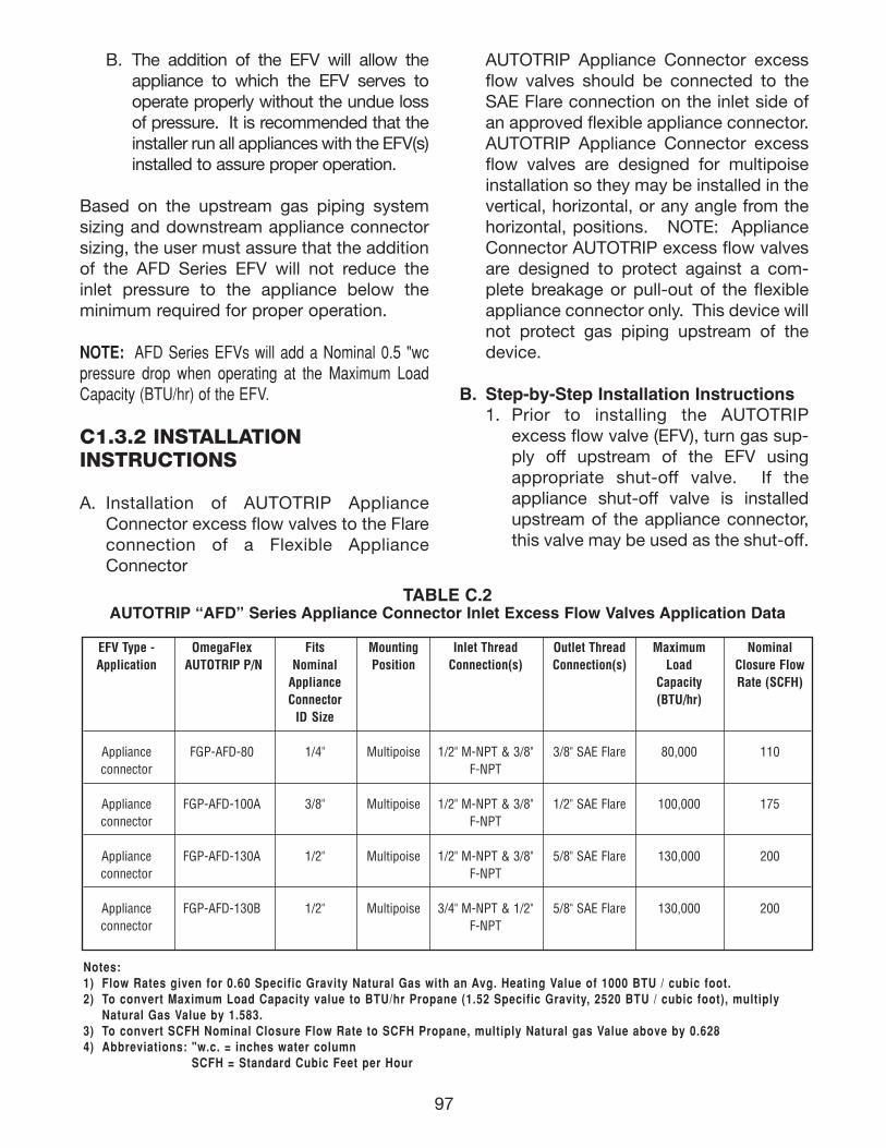
97
B. The addition of the EFV will allow theappliance to which the EFV serves tooperate properly without the undue lossof pressure. It is recommended that theinstaller run all appliances with the EFV(s)installed to assure proper operation.
Based on the upstream gas piping systemsizing and downstream appliance connectorsizing, the user must assure that the additionof the AFD Series EFV will not reduce theinlet pressure to the appliance below theminimum required for proper operation.
NOTE: AFD Series EFVs will add a Nominal 0.5 "wcpressure drop when operating at the Maximum LoadCapacity (BTU/hr) of the EFV.
C1.3.2 INSTALLATION INSTRUCTIONS
A. Installation of AUTOTRIP ApplianceConnector excess flow valves to the Flareconnection of a Flexible ApplianceConnector
AUTOTRIP Appliance Connector excessflow valves should be connected to theSAE Flare connection on the inlet side ofan approved flexible appliance connector.AUTOTRIP Appliance Connector excessflow valves are designed for multipoiseinstallation so they may be installed in thevertical, horizontal, or any angle from thehorizontal, positions. NOTE: ApplianceConnector AUTOTRIP excess flow valvesare designed to protect against a com-plete breakage or pull-out of the flexibleappliance connector only. This device willnot protect gas piping upstream of thedevice.
B. Step-by-Step Installation Instructions1. Prior to installing the AUTOTRIP
excess flow valve (EFV), turn gas sup-ply off upstream of the EFV usingappropriate shut-off valve. If theappliance shut-off valve is installedupstream of the appliance connector,this valve may be used as the shut-off.
TABLE C.2AUTOTRIP “AFD” Series Appliance Connector Inlet Excess Flow Valves Application Data
EFV Type - OmegaFlex Fits Mounting Inlet Thread Outlet Thread Maximum NominalApplication AUTOTRIP P/N Nominal Position Connection(s) Connection(s) Load Closure Flow
Appliance Capacity Rate (SCFH)Connector (BTU/hr)
ID Size
Appliance FGP-AFD-80 1/4" Multipoise 1/2" M-NPT & 3/8" 3/8" SAE Flare 80,000 110connector F-NPT
Appliance FGP-AFD-100A 3/8" Multipoise 1/2" M-NPT & 3/8" 1/2" SAE Flare 100,000 175connector F-NPT
Appliance FGP-AFD-130A 1/2" Multipoise 1/2" M-NPT & 3/8" 5/8" SAE Flare 130,000 200connector F-NPT
Appliance FGP-AFD-130B 1/2" Multipoise 3/4" M-NPT & 1/2" 5/8" SAE Flare 130,000 200connector F-NPT
Notes:1) Flow Rates given for 0.60 Specific Gravity Natural Gas with an Avg. Heating Value of 1000 BTU / cubic foot.2) To convert Maximum Load Capacity value to BTU/hr Propane (1.52 Specific Gravity, 2520 BTU / cubic foot), multiply
Natural Gas Value by 1.583.3) To convert SCFH Nominal Closure Flow Rate to SCFH Propane, multiply Natural gas Value above by 0.6284) Abbreviations: "w.c. = inches water column
SCFH = Standard Cubic Feet per Hour
111743_OmegaFlex_Txt:111743_OmegaFlex_Txt 5/28/09 11:57 AM Page 97
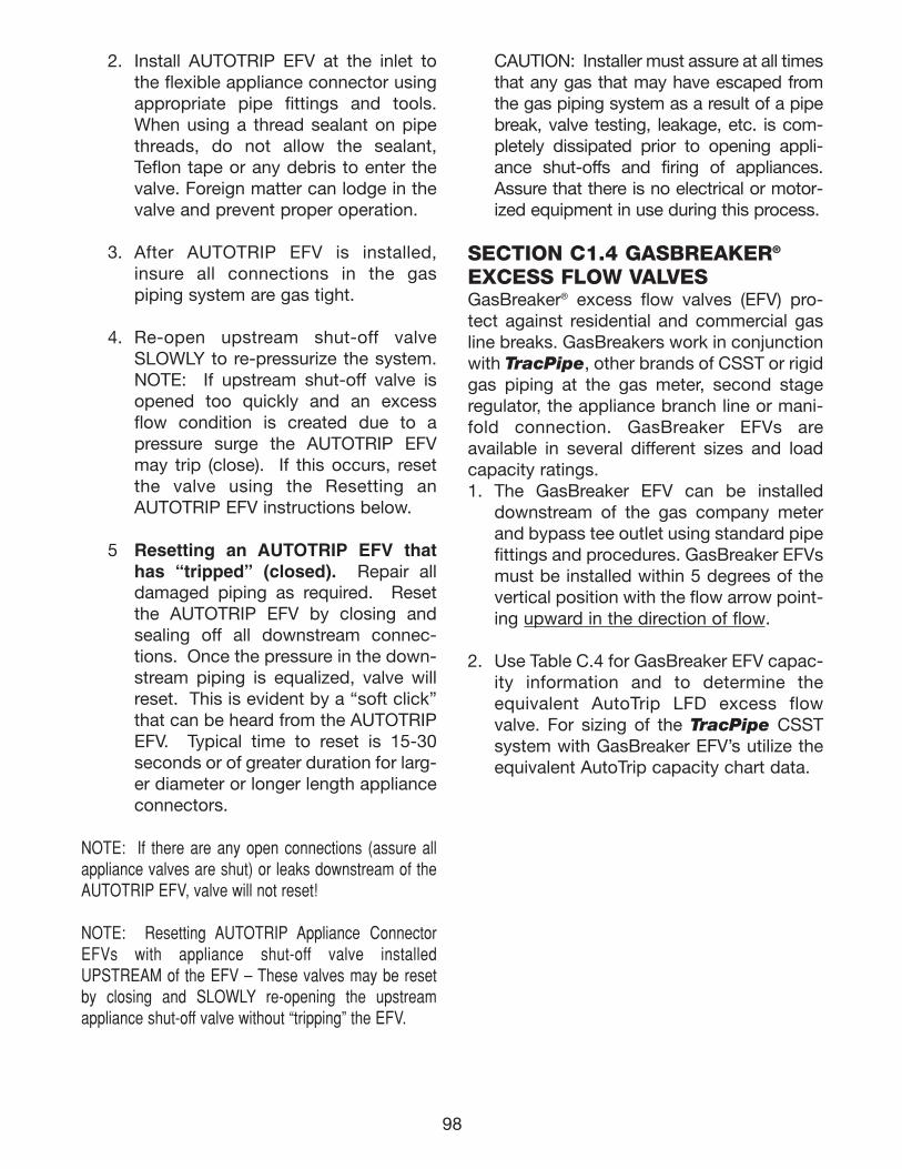
98
2. Install AUTOTRIP EFV at the inlet tothe flexible appliance connector usingappropriate pipe fittings and tools.When using a thread sealant on pipethreads, do not allow the sealant,Teflon tape or any debris to enter thevalve. Foreign matter can lodge in thevalve and prevent proper operation.
3. After AUTOTRIP EFV is installed,insure all connections in the gas piping system are gas tight.
4. Re-open upstream shut-off valveSLOWLY to re-pressurize the system.NOTE: If upstream shut-off valve isopened too quickly and an excessflow condition is created due to apressure surge the AUTOTRIP EFVmay trip (close). If this occurs, resetthe valve using the Resetting anAUTOTRIP EFV instructions below.
5 Resetting an AUTOTRIP EFV thathas “tripped” (closed). Repair alldamaged piping as required. Resetthe AUTOTRIP EFV by closing andsealing off all downstream connec-tions. Once the pressure in the down-stream piping is equalized, valve willreset. This is evident by a “soft click”that can be heard from the AUTOTRIPEFV. Typical time to reset is 15-30seconds or of greater duration for larg-er diameter or longer length applianceconnectors.
NOTE: If there are any open connections (assure allappliance valves are shut) or leaks downstream of theAUTOTRIP EFV, valve will not reset!
NOTE: Resetting AUTOTRIP Appliance ConnectorEFVs with appliance shut-off valve installedUPSTREAM of the EFV – These valves may be resetby closing and SLOWLY re-opening the upstream appliance shut-off valve without “tripping” the EFV.
CAUTION: Installer must assure at all timesthat any gas that may have escaped fromthe gas piping system as a result of a pipebreak, valve testing, leakage, etc. is com-pletely dissipated prior to opening appli-ance shut-offs and firing of appliances.Assure that there is no electrical or motor-ized equipment in use during this process.
SECTION C1.4 GASBREAKER®
EXCESS FLOW VALVES GasBreaker® excess flow valves (EFV) pro-tect against residential and commercial gasline breaks. GasBreakers work in conjunctionwith TracPipe, other brands of CSST or rigidgas piping at the gas meter, second stageregulator, the appliance branch line or mani-fold connection. GasBreaker EFVs are available in several different sizes and loadcapacity ratings.1. The GasBreaker EFV can be installed
downstream of the gas company meterand bypass tee outlet using standard pipefittings and procedures. GasBreaker EFVsmust be installed within 5 degrees of thevertical position with the flow arrow point-ing upward in the direction of flow.
2. Use Table C.4 for GasBreaker EFV capac-ity information and to determine theequivalent AutoTrip LFD excess flowvalve. For sizing of the TracPipe CSSTsystem with GasBreaker EFV’s utilize theequivalent AutoTrip capacity chart data.
111743_OmegaFlex_Txt:111743_OmegaFlex_Txt 5/28/09 11:57 AM Page 98
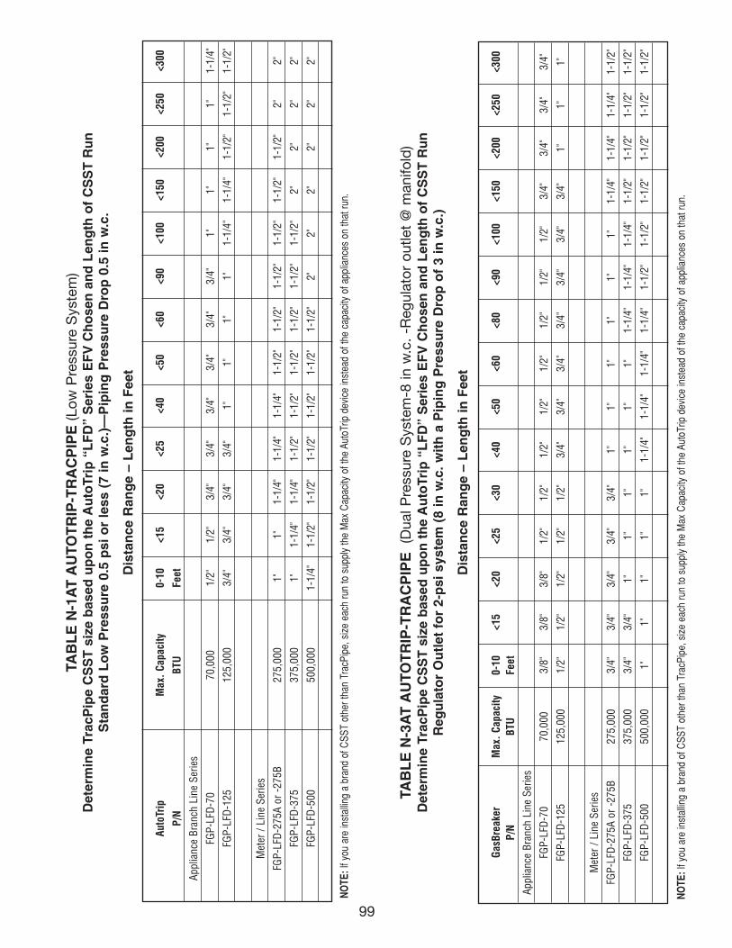
99
TAB
LE
N-1
AT
AU
TOT
RIP
-TR
AC
PIP
E (L
ow P
ress
ure
Sys
tem
)D
eter
min
e Tr
acP
ipe
CS
ST
siz
e b
ased
up
on
th
e A
uto
Trip
“L
FD
” S
erie
s E
FV
Ch
ose
n a
nd
Len
gth
of
CS
ST
Ru
nS
tan
dar
d L
ow
Pre
ssu
re 0
.5 p
si o
r le
ss (
7 in
w.c
.)—
Pip
ing
Pre
ssu
re D
rop
0.5
in w
.c.
Dis
tan
ce R
ang
e –
Len
gth
in F
eet
TAB
LE
N-3
AT
AU
TOT
RIP
-TR
AC
PIP
E
(Dua
l Pre
ssur
e S
yste
m-8
in w
.c.
-Reg
ulat
or o
utle
t @
man
ifold
)D
eter
min
e Tr
acP
ipe
CS
ST
siz
e b
ased
up
on
th
e A
uto
Trip
“L
FD
” S
erie
s E
FV
Ch
ose
n a
nd
Len
gth
of
CS
ST
Ru
nR
egu
lato
r O
utl
et f
or
2-p
si s
yste
m (
8 in
w.c
. wit
h a
Pip
ing
Pre
ssu
re D
rop
of
3 in
w.c
.)
Dis
tan
ce R
ang
e –
Len
gth
in F
eet
Gas
Brea
ker
Max
. Ca
paci
ty0-
10
<15
<20
<25
<30
<40
<50
<60
<80
<90
<100
<150
<200
<250
<300
P/N
BTU
Feet
Appl
ianc
e Br
anch
Lin
e Se
ries
FGP-
LFD
-70
70,0
003/
8"3/
8"3/
8"1/
2"1/
2"
1/2"
1/2"
1/2"
1/2"
1/2"
1/2"
3/4"
3/4"
3/4"
3/4"
FGP-
LFD
-125
125,
000
1/2"
1/2"
1/2"
1/2"
1/2"
3/4"
3/4"
3/4"
3/4"
3/4"
3/4"
3/4"
1"1"
1"
Met
er /
Line
Ser
ies
FGP-
LFD
-275
A or
-27
5B27
5,00
03/
4"3/
4"3/
4"3/
4"3/
4"1"
1"1"
1"1"
1"1-
1/4"
1-1/
4"1-
1/4"
1-1/
2"
FGP-
LFD
-375
375,
000
3/4"
3/4"
1"1"
1"1"
1"1"
1-1/
4"1-
1/4"
1-1/
4"1-
1/2"
1-1/
2"1-
1/2"
1-1/
2"
FGP-
LFD
-500
500,
000
1"1"
1"1"
1"1-
1/4"
1-1/
4"1-
1/4"
1-1/
4"1-
1/2"
1-1/
2"1-
1/2"
1-1/
2"1-
1/2"
1-1/
2"
NO
TE:I
f you
are
inst
allin
g a
bran
d of
CSS
T ot
her t
han
Trac
Pipe
, siz
e ea
ch ru
n to
sup
ply
the
Max
Cap
acity
of t
he A
utoT
rip d
evic
e in
stea
d of
the
capa
city
of a
pplia
nces
on
that
run.
Auto
Trip
Max
. Ca
paci
ty0-
10
<15
<20
<25
<40
<50
<60
<90
<100
<150
<200
<250
<300
P/N
BTU
Feet
Appl
ianc
e Br
anch
Lin
e Se
ries
FGP-
LFD
-70
70,0
001/
2"1/
2"3/
4"3/
4"3/
4"3/
4"3/
4"3/
4"1"
1"1"
1"1-
1/4"
FGP-
LFD
-125
125,
000
3/4"
3/4"
3/4"
3/4"
1"1"
1"1"
1-1/
4"1-
1/4"
1-1/
2"1-
1/2"
1-1/
2"
Met
er /
Line
Ser
ies
FGP-
LFD
-275
A or
-27
5B27
5,00
01"
1"1-
1/4"
1-1/
4"1-
1/4"
1-1/
2"1-
1/2"
1-1/
2"1-
1/2"
1-1/
2"1-
1/2"
2"2"
FGP-
LFD
-375
375,
000
1"1-
1/4"
1-1/
4"1-
1/2"
1-1/
2"1-
1/2"
1-1/
2"1-
1/2"
1-1/
2"2"
2"2"
2"
FGP-
LFD
-500
500,
000
1-1/
4"1-
1/2"
1-1/
2"1-
1/2"
1-1/
2"1-
1/2"
1-1/
2"2"
2"2"
2"2"
2"
NO
TE:I
f you
are
inst
allin
g a
bran
d of
CSS
T ot
her t
han
Trac
Pipe
, siz
e ea
ch ru
n to
sup
ply
the
Max
Cap
acity
of t
he A
utoT
rip d
evic
e in
stea
d of
the
capa
city
of a
pplia
nces
on
that
run.
111743_OmegaFlex_Txt:111743_OmegaFlex_Txt 5/28/09 11:57 AM Page 99
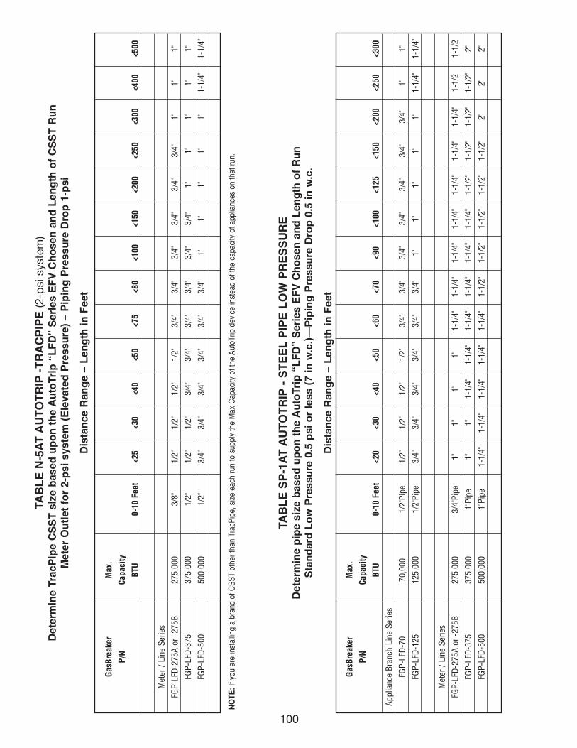
100
TAB
LE
N-5
AT
AU
TOT
RIP
-T
RA
CP
IPE
(2-p
si s
yste
m)
Det
erm
ine
Trac
Pip
e C
SS
T s
ize
bas
ed u
po
n t
he
Au
toTr
ip “
LF
D”
Ser
ies
EF
V C
ho
sen
an
d L
eng
th o
f C
SS
T R
un
Met
er O
utl
et f
or
2-p
si s
yste
m (
Ele
vate
d P
ress
ure
) –
Pip
ing
Pre
ssu
re D
rop
1-p
si
Dis
tan
ce R
ang
e –
Len
gth
in F
eet
Gas
Brea
ker
Max
.
P/N
Capa
city
BTU
0-10
Fee
t<2
5<3
0<4
0<5
0<7
5<8
0<1
00<1
50<2
00<2
50<3
00<4
00<5
00
Met
er /
Line
Ser
ies
FGP-
LFD
-275
A or
-27
5B27
5,00
03/
8"1/
2"1/
2"1/
2"1/
2"3/
4"3/
4"3/
4"3/
4"3/
4"3/
4"1"
1"1"
FGP-
LFD
-375
375,
000
1/2"
1/2"
1/2"
3/4"
3/4"
3/4"
3/4"
3/4"
3/4"
1"1"
1"1"
1"
FGP-
LFD
-500
500,
000
1/2"
3/4"
3/4"
3/4"
3/4"
3/4"
3/4"
1"1"
1"1"
1"1-
1/4"
1-1/
4"
Gas
Brea
ker
Max
.
P/N
Capa
city
BTU
0-10
Fee
t<2
0<3
0<4
0<5
0<6
0<7
0<9
0<1
00<1
25<1
50<2
00<2
50<3
00
Appl
ianc
e Br
anch
Lin
e Se
ries
FGP-
LFD
-70
70,0
001/
2"Pi
pe1/
2"1/
2"1/
2"1/
2"3/
4"3/
4"3/
4"3/
4"3/
4"3/
4"3/
4"1"
1"
FGP-
LFD
-125
125,
000
1/2"
Pipe
3/4"
3/4"
3/4"
3/4"
3/4"
3/4"
1"1"
1"1"
1"1-
1/4"
1-1/
4"
Met
er /
Line
Ser
ies
FGP-
LFD
-275
A or
-27
5B27
5,00
03/
4"Pi
pe1"
1"1"
1"1-
1/4"
1-1/
4"1-
1/4"
1-1/
4"1-
1/4"
1-1/
4"1-
1/4"
1-1/
21-
1/2
FGP-
LFD
-375
375,
000
1"Pi
pe1"
1"1-
1/4"
1-1/
4"1-
1/4"
1-1/
4"1-
1/4"
1-1/
4"1-
1/2"
1-1/
2"1-
1/2"
1-1/
2"2"
FGP-
LFD
-500
500,
000
1"Pi
pe1-
1/4"
1-1/
4"1-
1/4"
1-1/
4"1-
1/4"
1-1/
2"1-
1/2"
1-1/
2"1-
1/2"
1-1/
2"2"
2"2"
TAB
LE
SP
-1A
T A
UTO
TR
IP -
ST
EE
L P
IPE
LO
W P
RE
SS
UR
ED
eter
min
e p
ipe
size
bas
ed u
po
n t
he
Au
toTr
ip “
LF
D”
Ser
ies
EF
V C
ho
sen
an
d L
eng
th o
f R
un
Sta
nd
ard
Lo
w P
ress
ure
0.5
psi
or
less
(7
in w
.c.)
—P
ipin
g P
ress
ure
Dro
p 0
.5 in
w.c
.
Dis
tan
ce R
ang
e –
Len
gth
in F
eet
NO
TE:I
f you
are
inst
allin
g a
bran
d of
CSS
T ot
her t
han
Trac
Pipe
, siz
e ea
ch ru
n to
sup
ply
the
Max
Cap
acity
of t
he A
utoT
rip d
evic
e in
stea
d of
the
capa
city
of a
pplia
nces
on
that
run.
111743_OmegaFlex_Txt:111743_OmegaFlex_Txt 5/28/09 11:57 AM Page 100
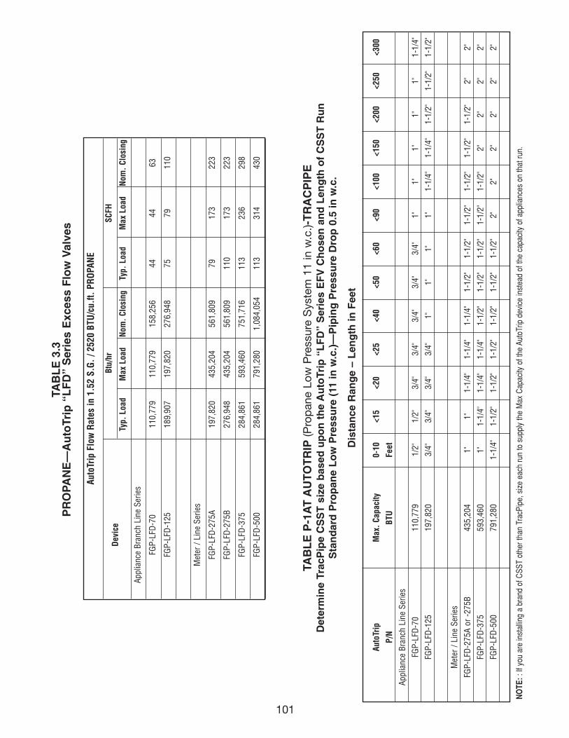
101
Auto
Trip
Flo
w R
ates
in 1
.52
S.G
. / 2
520
BTU
/cu.
ft. P
RO
PAN
E
Dev
ice
Btu/
hrSC
FH
Typ.
Loa
dM
ax L
oad
Nom
. Cl
osin
gTy
p. L
oad
Max
Loa
dN
om.
Clos
ing
Appl
ianc
e Br
anch
Lin
e Se
ries
FGP-
LFD
-70
110,
779
110,
779
158,
256
4444
63
FGP-
LFD
-125
189,
907
197,
820
276,
948
7579
110
Met
er /
Line
Ser
ies
FGP-
LFD
-275
A19
7,82
043
5,20
456
1,80
979
173
223
FGP-
LFD
-275
B27
6,94
843
5,20
456
1,80
911
017
322
3
FGP-
LFD
-375
284,
861
593,
460
751,
716
113
236
298
FGP-
LFD
-500
284,
861
791,
280
1,08
4,05
411
331
443
0
TAB
LE
3.3
PR
OPA
NE
—A
uto
Trip
“L
FD
” S
erie
s E
xces
s F
low
Val
ves
TAB
LE
P-1
AT
AU
TOT
RIP
(Pro
pan
e Lo
w P
ress
ure
Sys
tem
11
in w
.c.)-
TR
AC
PIP
ED
eter
min
e Tr
acP
ipe
CS
ST
siz
e b
ased
up
on
th
e A
uto
Trip
“L
FD
” S
erie
s E
FV
Ch
ose
n a
nd
Len
gth
of
CS
ST
Ru
nS
tan
dar
d P
rop
ane
Lo
w P
ress
ure
(11
in w
.c.)
—P
ipin
g P
ress
ure
Dro
p 0
.5 in
w.c
.
Dis
tan
ce R
ang
e –
Len
gth
in F
eet
Auto
Trip
Max
. Ca
paci
ty0-
10
<15
<20
<25
<40
<50
<60
<90
<100
<150
<200
<250
<300
P/N
BTU
Feet
Appl
ianc
e Br
anch
Lin
e Se
ries
FGP-
LFD
-70
110,
779
1/2"
1/2"
3/4"
3/4"
3/4"
3/4"
3/4"
1"1"
1"1"
1"1-
1/4"
FGP-
LFD
-125
197,
820
3/4"
3/4"
3/4"
3/4"
1"1"
1"1"
1-1/
4"1-
1/4"
1-1/
2"1-
1/2"
1-1/
2"
Met
er /
Line
Ser
ies
FGP-
LFD
-275
A or
-27
5B43
5,20
41"
1"1-
1/4"
1-1/
4"1-
1/4"
1-1/
2"1-
1/2"
1-1/
2"1-
1/2"
1-1/
2"1-
1/2"
2"2"
FGP-
LFD
-375
593,
460
1"1-
1/4"
1-1/
4"1-
1/4"
1-1/
2"1-
1/2"
1-1/
2"1-
1/2"
1-1/
2"2"
2"2"
2"
FGP-
LFD
-500
791,
280
1-1/
4"1-
1/2"
1-1/
2"1-
1/2"
1-1/
2"1-
1/2"
1-1/
2"2"
2"2"
2"2"
2"
NO
TE::
If y
ou a
re in
stal
ling
a br
and
of C
SST
othe
r tha
n Tr
acPi
pe, s
ize
each
run
to s
uppl
y th
e M
ax C
apac
ity o
f the
Aut
oTrip
dev
ice
inst
ead
of th
e ca
paci
ty o
f app
lianc
es o
n th
at ru
n.
111743_OmegaFlex_Txt:111743_OmegaFlex_Txt 5/28/09 11:57 AM Page 101
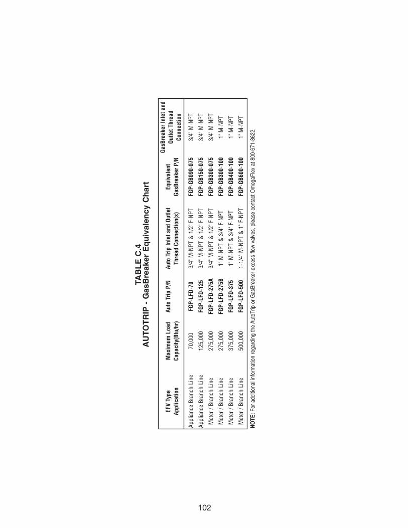
102
EFV
Type
Max
imum
Loa
dAu
to T
rip
P/N
Auto
Tri
p In
let a
nd O
utle
tEq
uiva
lent
Gas
Brea
ker
Inle
t and
Appl
icat
ion
Capa
city
(Btu
/hr)
Thre
ad C
onne
ctio
n(s)
Gas
Brea
ker
P/N
Out
let T
hrea
dCo
nnec
tion
Appl
ianc
e Br
anch
Lin
e70
,000
FGP-
LFD
-70
3/4"
M-N
PT &
1/2
" F-N
PTFG
P-G
B090
-075
3/4"
M-N
PT
Appl
ianc
e Br
anch
Lin
e12
5,00
0FG
P-LF
D-1
253/
4" M
-NPT
& 1
/2" F
-NPT
FGP-
GB1
50-0
753/
4" M
-NPT
Met
er /
Bran
ch L
ine
275,
000
FGP-
LFD
-275
A3/
4" M
-NPT
& 1
/2" F
-NPT
FGP-
GB3
00-0
753/
4" M
-NPT
Met
er /
Bran
ch L
ine
275,
000
FGP-
LFD
-275
B1"
M-N
PT &
3/4
" F-N
PTFG
P-G
B300
-100
1" M
-NPT
Met
er /
Bran
ch L
ine
375,
000
FGP-
LFD
-375
1" M
-NPT
& 3
/4" F
-NPT
FGP-
GB4
00-1
001"
M-N
PT
Met
er /
Bran
ch L
ine
500,
000
FGP-
LFD
-500
1-1/
4" M
-NPT
& 1
" F-N
PTFG
P-G
B600
-100
1" M
-NPT
TAB
LE
C.4
AU
TOT
RIP
- G
asB
reak
er E
qu
ival
ency
Ch
art
NO
TE:F
or a
dditi
onal
info
rmat
ion
rega
rdin
g th
e Au
toTr
ip o
r Gas
Brea
ker e
xces
s flo
w v
alve
s, p
leas
e co
ntac
t Om
egaF
lex
at 8
00-6
71-8
622.
111743_OmegaFlex_Txt:111743_OmegaFlex_Txt 5/28/09 11:57 AM Page 102
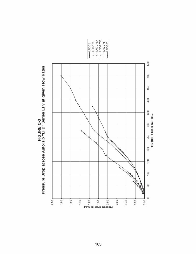
103
0.00
0.20
0.40
0.60
0.80
1.00
1.20
1.40
1.60
1.80
2.00
050
100
150
200
250
300
350
400
450
500
550
Flow
(CFH
0.6
S.G
. Nat
. Gas
)
Pressure drop (in. w.c.)
LFD
-70
LFD
-125
LFD
-275
ALF
D-2
75B
LFD
-375
LFD
-500
FIG
UR
E C
-3P
ress
ure
Dro
p a
cro
ss A
uto
Trip
“L
FD
” S
erie
s E
FV
at
giv
en F
low
Rat
es
111743_OmegaFlex_Txt:111743_OmegaFlex_Txt 5/28/09 11:57 AM Page 103

NOTES:
111743_OmegaFlex_Txt:111743_OmegaFlex_Txt 5/28/09 11:57 AM Page 104

111743_OmegaFlex_Cvr:111743_OmegaFlex_Cvr 5/26/09 4:43 PM Page 3

OMEGAFLEX ®
451 Creamery WayExton, PA 19341-2509610-524-7272 Fax: 610-524-7282www.omegaflex.com
1-800-671-8622
111743_OmegaFlex_Cvr:111743_OmegaFlex_Cvr 5/26/09 4:43 PM Page 4