Embed Size (px)
Citation preview
intelligent Converged Network consolidating Radio and optical access aRoundUSer equipment
Flexible Ethernet Fronthaul
Nathan J. Gomes
iCIRRUS Project Coordinator/Technical ManagerCommunications Research Group, University of Kent, UK

Mobile fronthaul State-of-the-art, challenges
Moving the functional split and the new, flexible fronthaul
Transport requirements for the new, flexible fronthaul Delay variation challenges
Implications
Overview
1st 5G Architecture Workshop, Brussels, 6 April, 2016
Mobile Fronthaul
1st 5G Architecture Workshop, Brussels, 6 April, 2016
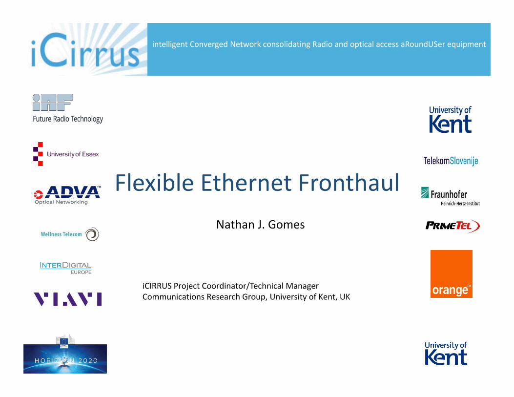
Reliable transport of 3 basic flows
User Data
IQ samples in current fronthaul
Control and Management (C&M)
BBU <-> RRH (DU <-> RU)
Higher layer eNB <-> UE, UE <-> ePC
Synchronisation
Frequency
Phase/Time
User Data
C&M
Sync
Fronthaul
Currently used fronthaul technology overwhelmingly based on Common Public Radio Interface (CPRI)
Advantages: Disadvantages:Fully centralised -> Sampled waveforms -> high bit-rates!maximises virtualisation benefits Multiple antenna streams -> high-bit rates!!Synchronous, TDM-based -> Little or no statistical multiplexing gains in aggregation inherently robust to timing -> high bit-rates!!!
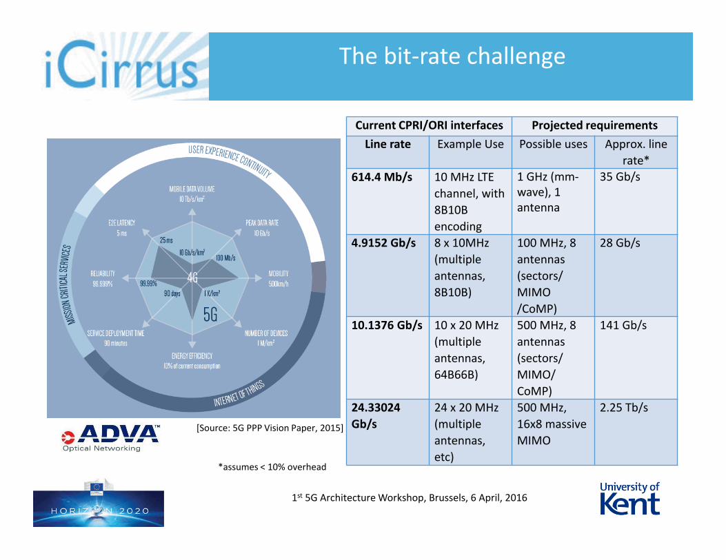
The bit-rate challenge
1st 5G Architecture Workshop, Brussels, 6 April, 2016
[Source: 5G PPP Vision Paper, 2015]
Current CPRI/ORI interfaces Projected requirements
Line rate Example Use Possible uses Approx. line
rate*
614.4 Mb/s 10 MHz LTE
channel, with
8B10B
encoding
1 GHz (mm-wave), 1 antenna
35 Gb/s
4.9152 Gb/s 8 x 10MHz
(multiple
antennas,
8B10B)
100 MHz, 8
antennas
(sectors/
MIMO
/CoMP)
28 Gb/s
10.1376 Gb/s 10 x 20 MHz
(multiple
antennas,
64B66B)
500 MHz, 8
antennas
(sectors/
MIMO/
CoMP)
141 Gb/s
24.33024
Gb/s
24 x 20 MHz
(multiple
antennas,
etc)
500 MHz,
16x8 massive
MIMO
2.25 Tb/s
*assumes < 10% overhead
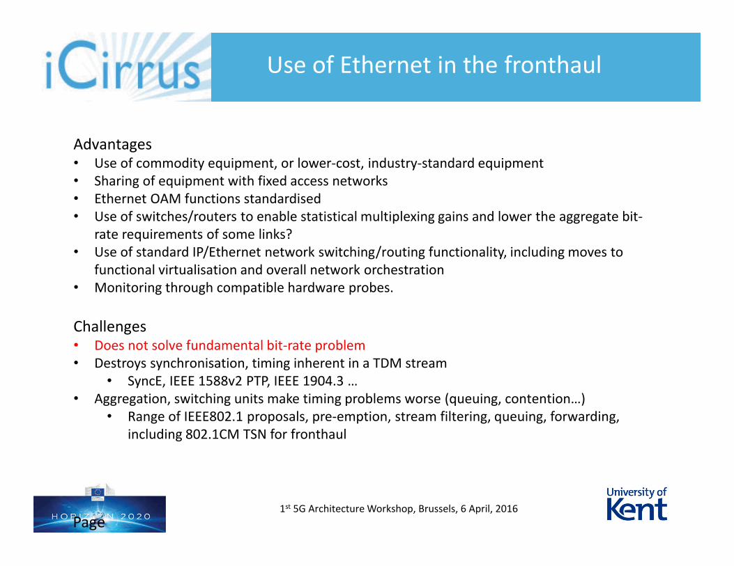
Use of Ethernet in the fronthaul
Advantages• Use of commodity equipment, or lower-cost, industry-standard equipment• Sharing of equipment with fixed access networks• Ethernet OAM functions standardised• Use of switches/routers to enable statistical multiplexing gains and lower the aggregate bit-
rate requirements of some links?• Use of standard IP/Ethernet network switching/routing functionality, including moves to
functional virtualisation and overall network orchestration• Monitoring through compatible hardware probes.
Challenges• Does not solve fundamental bit-rate problem• Destroys synchronisation, timing inherent in a TDM stream
• SyncE, IEEE 1588v2 PTP, IEEE 1904.3 …• Aggregation, switching units make timing problems worse (queuing, contention…)
• Range of IEEE802.1 proposals, pre-emption, stream filtering, queuing, forwarding, including 802.1CM TSN for fronthaul
1st 5G Architecture Workshop, Brussels, 6 April, 2016
Page 5
Mobile fronthaul State-of-the-art, challenges
Moving the functional split and the new, flexible fronthaul
Transport requirements for the new, flexible fronthaul Delay variation challenges
Implications
Overview
1st 5G Architecture Workshop, Brussels, 6 April, 2016
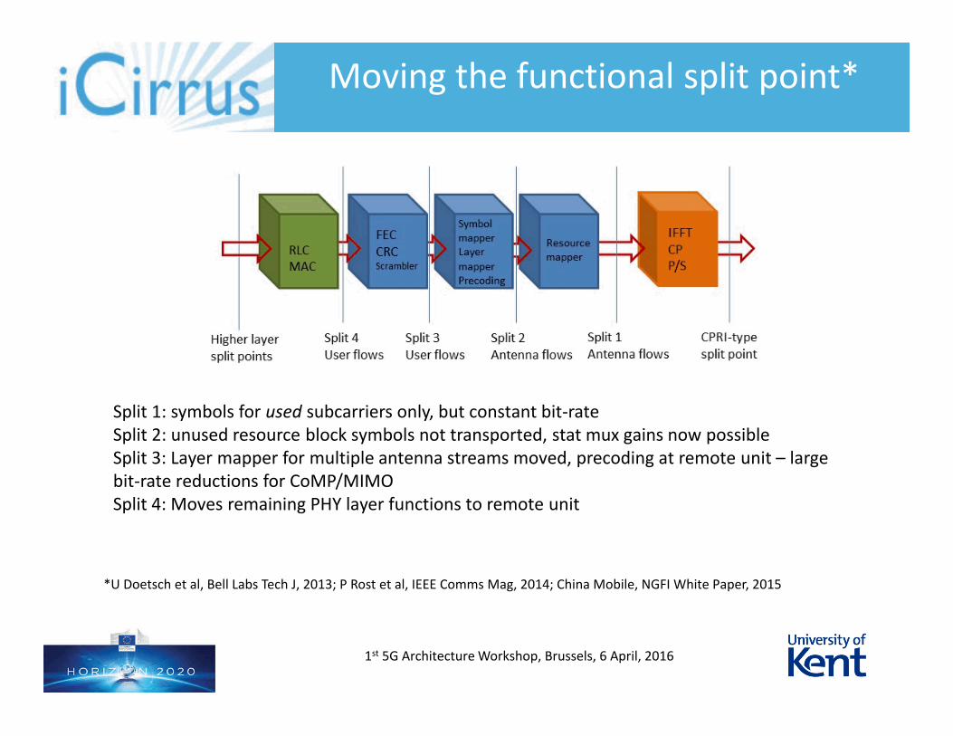
Moving the functional split point*
1st 5G Architecture Workshop, Brussels, 6 April, 2016
Split 1: symbols for used subcarriers only, but constant bit-rateSplit 2: unused resource block symbols not transported, stat mux gains now possibleSplit 3: Layer mapper for multiple antenna streams moved, precoding at remote unit – large bit-rate reductions for CoMP/MIMOSplit 4: Moves remaining PHY layer functions to remote unit
*U Doetsch et al, Bell Labs Tech J, 2013; P Rost et al, IEEE Comms Mag, 2014; China Mobile, NGFI White Paper, 2015
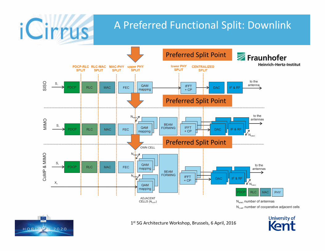
A Preferred Functional Split: Downlink
1st 5G Architecture Workshop, Brussels, 6 April, 2016
Preferred Split Point
Preferred Split Point
Preferred Split Point
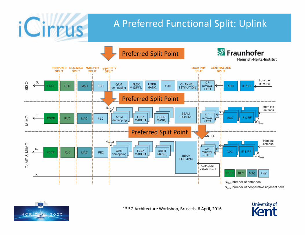
A Preferred Functional Split: Uplink
1st 5G Architecture Workshop, Brussels, 6 April, 2016
Preferred Split Point
Preferred Split Point
Preferred Split Point
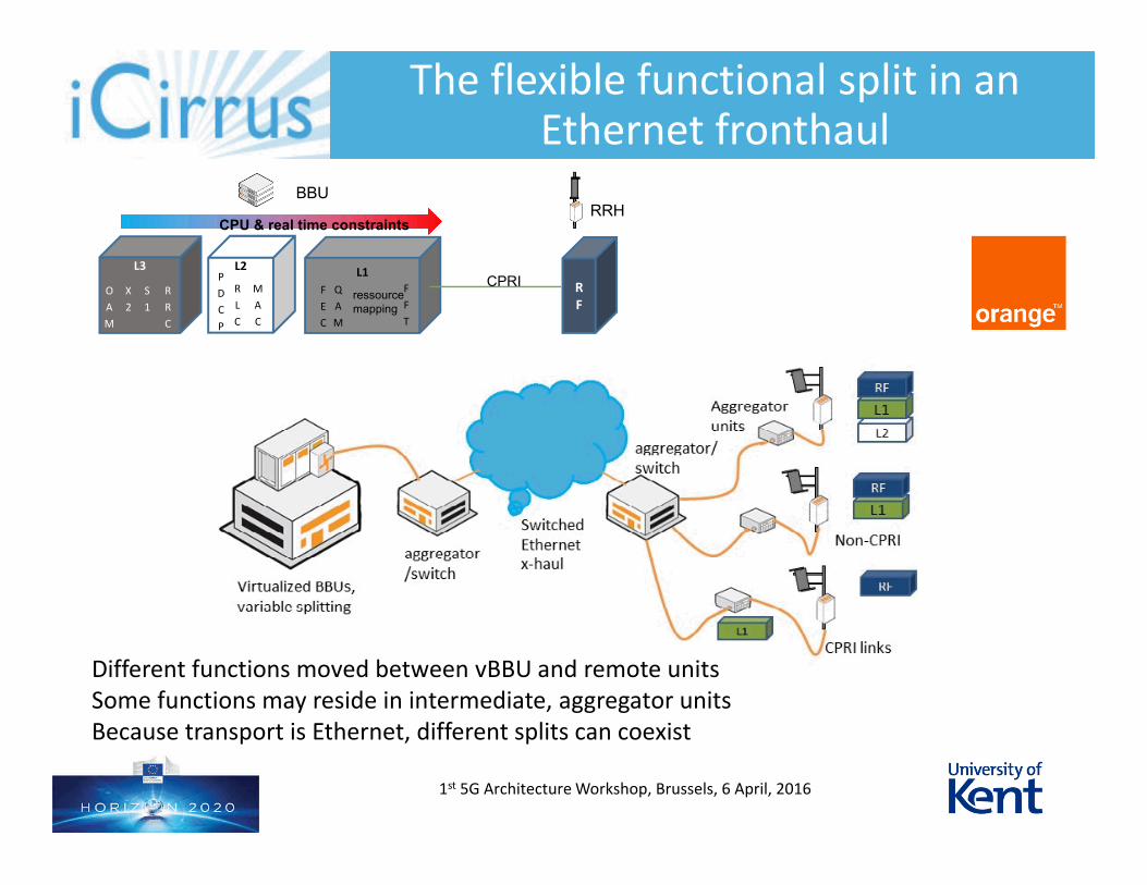
The flexible functional split in an Ethernet fronthaul
1st 5G Architecture Workshop, Brussels, 6 April, 2016
L2
RF
L1F
F
T
ressourcemapping
Q
A
M
F
E
C
R
L
C
M
A
C
P
D
C
P
L3
S
1
R
R
C
X
2
O
A
M
BBURRH
CPRI
CPU & real time constraints
Different functions moved between vBBU and remote unitsSome functions may reside in intermediate, aggregator unitsBecause transport is Ethernet, different splits can coexist
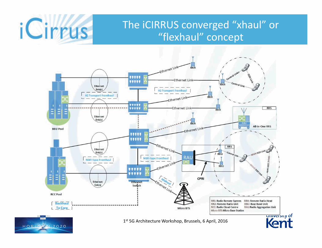
The iCIRRUS converged “xhaul” or “flexhaul” concept
1st 5G Architecture Workshop, Brussels, 6 April, 2016

Mobile fronthaul State-of-the-art, challenges
Moving the functional split and the new, flexible fronthaul
Transport requirements for the new, flexible fronthaul Delay variation challenges
Implications
Overview
1st 5G Architecture Workshop, Brussels, 6 April, 2016
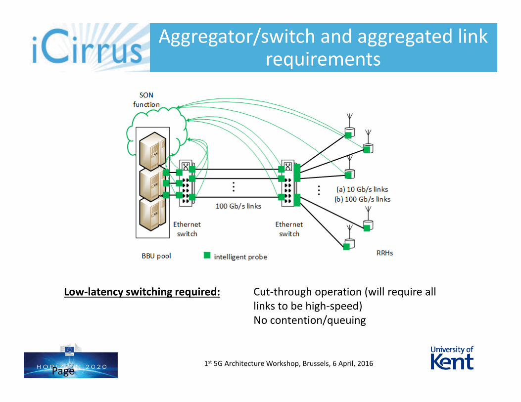
Aggregator/switch and aggregated link requirements
Low-latency switching required: Cut-through operation (will require all links to be high-speed)No contention/queuing
1st 5G Architecture Workshop, Brussels, 6 April, 2016Page 13
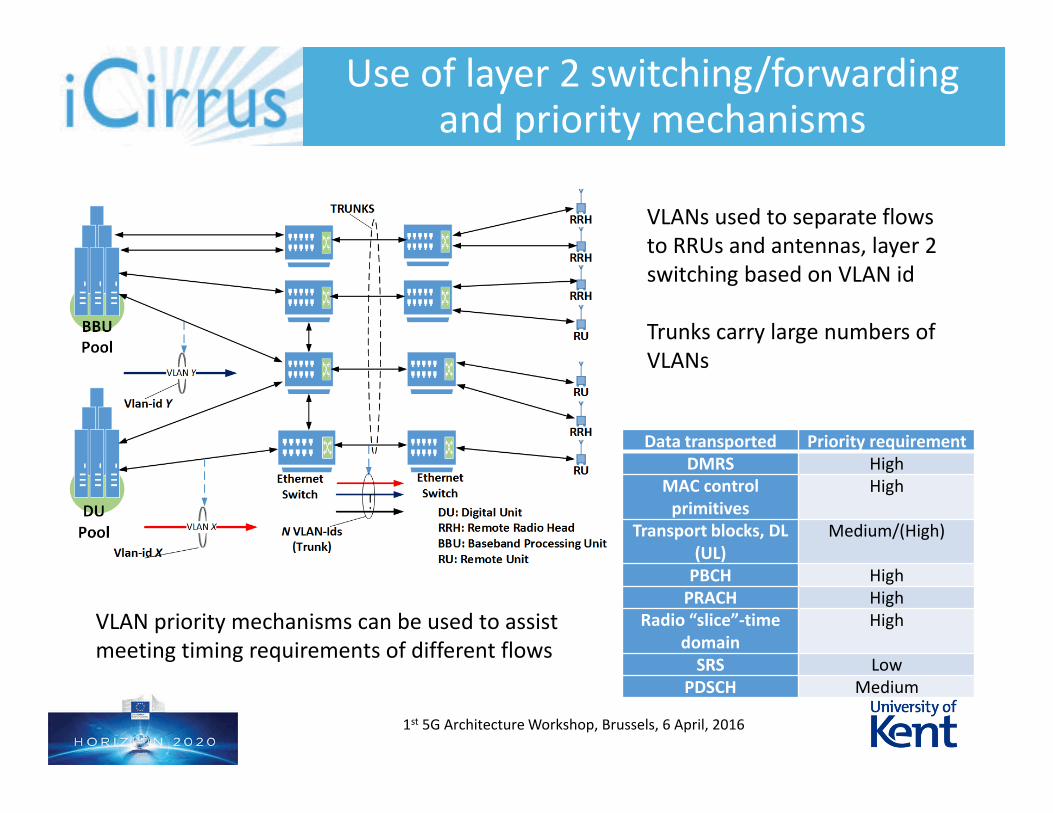
Use of layer 2 switching/forwarding and priority mechanisms
1st 5G Architecture Workshop, Brussels, 6 April, 2016
Data transported Priority requirementDMRS High
MAC control primitives
High
Transport blocks, DL (UL)
Medium/(High)
PBCH HighPRACH High
Radio “slice”-time domain
High
SRS LowPDSCH Medium
VLANs used to separate flows to RRUs and antennas, layer 2 switching based on VLAN id
Trunks carry large numbers of VLANs
VLAN priority mechanisms can be used to assist meeting timing requirements of different flows
Mobile fronthaul State-of-the-art, challenges
Moving the functional split and the new, flexible fronthaul
Transport requirements for the new, flexible fronthaul Delay variation challenges
Implications
Overview
1st 5G Architecture Workshop, Brussels, 6 April, 2016
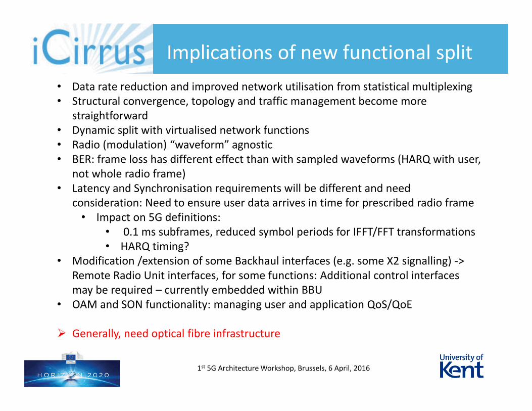
Implications of new functional split
1st 5G Architecture Workshop, Brussels, 6 April, 2016
• Data rate reduction and improved network utilisation from statistical multiplexing• Structural convergence, topology and traffic management become more
straightforward• Dynamic split with virtualised network functions• Radio (modulation) “waveform” agnostic• BER: frame loss has different effect than with sampled waveforms (HARQ with user,
not whole radio frame)• Latency and Synchronisation requirements will be different and need
consideration: Need to ensure user data arrives in time for prescribed radio frame• Impact on 5G definitions:
• 0.1 ms subframes, reduced symbol periods for IFFT/FFT transformations• HARQ timing?
• Modification /extension of some Backhaul interfaces (e.g. some X2 signalling) -> Remote Radio Unit interfaces, for some functions: Additional control interfaces may be required – currently embedded within BBU
• OAM and SON functionality: managing user and application QoS/QoE
Generally, need optical fibre infrastructure
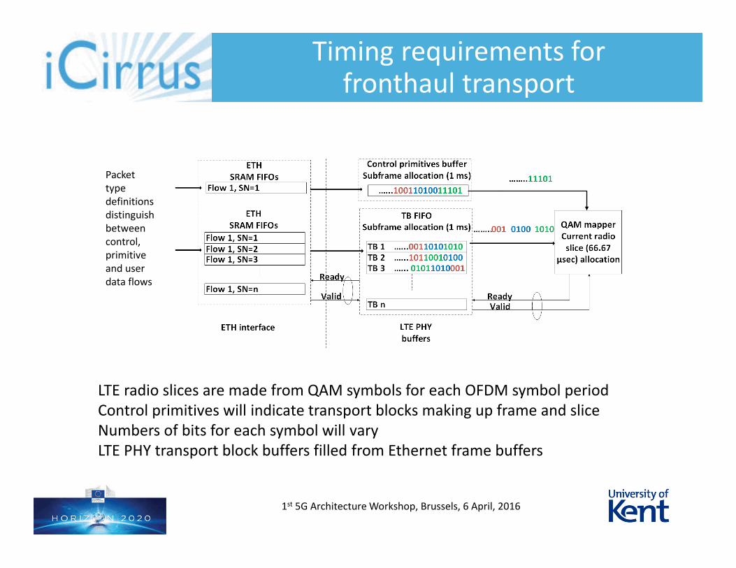
Timing requirements for fronthaul transport
1st 5G Architecture Workshop, Brussels, 6 April, 2016
Packet type definitions distinguish between control, primitive and user data flows
LTE radio slices are made from QAM symbols for each OFDM symbol periodControl primitives will indicate transport blocks making up frame and sliceNumbers of bits for each symbol will varyLTE PHY transport block buffers filled from Ethernet frame buffers
This presentation is property of the COMBO Consortium and shall not be distributed or reproduced without the formal approval of the Project Board
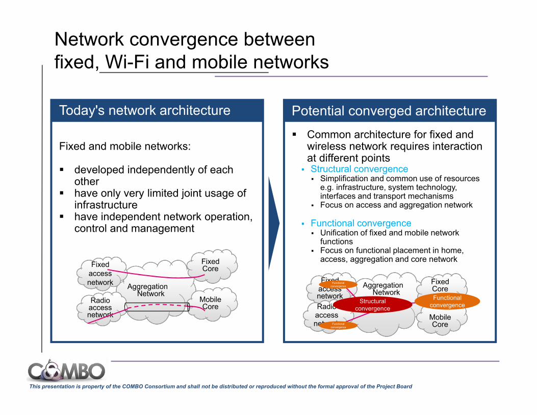
Fixed and mobile networks:
developed independently of each other
have only very limited joint usage of infrastructure
have independent network operation, control and management
Today's network architecture
Common architecture for fixed and wireless network requires interaction at different points
Structural convergence Simplification and common use of resources
e.g. infrastructure, system technology, interfaces and transport mechanisms
Focus on access and aggregation network
Functional convergence Unification of fixed and mobile network
functions Focus on functional placement in home,
access, aggregation and core network
Potential converged architecture
Aggregation Network
Fixed Core
Mobile Core
Fixed
network
Fixedaccess network
RadioRadioaccessnetwork
Aggregation Network
Fixed Fixed Core
Mobile Core
FixedFixedaccess network
RadioRadioaccessnetwork
Functional convergence
Structural convergence
Functional convergence
Functional convergence
Network convergence between fixed, Wi-Fi and mobile networks
This presentation is property of the COMBO Consortium and shall not be distributed or reproduced without the formal approval of the Project Board
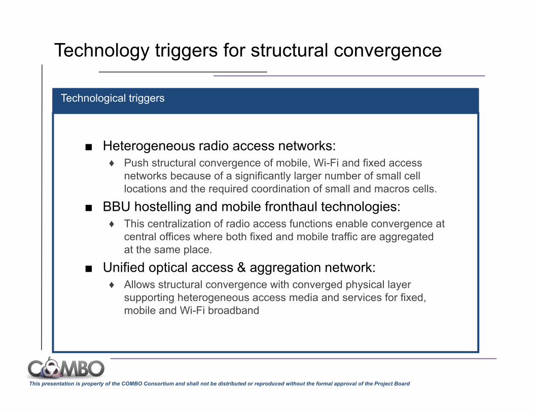
■ Heterogeneous radio access networks: ♦ Push structural convergence of mobile, Wi-Fi and fixed access
networks because of a significantly larger number of small cell locations and the required coordination of small and macros cells.
■ BBU hostelling and mobile fronthaul technologies: ♦ This centralization of radio access functions enable convergence at
central offices where both fixed and mobile traffic are aggregated at the same place.
■ Unified optical access & aggregation network: ♦ Allows structural convergence with converged physical layer
supporting heterogeneous access media and services for fixed, mobile and Wi-Fi broadband
Technological triggers
Technology triggers for structural convergence
This presentation is property of the COMBO Consortium and shall not be distributed or reproduced without the formal approval of the Project Board
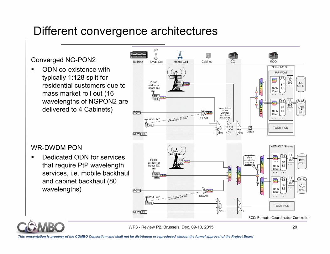
Different convergence architectures
RCC: Remote Coordinator Controller
Converged NG-PON2
ODN co-existence with typically 1:128 split for residential customers due to mass market roll out (16 wavelengths of NGPON2 are delivered to 4 Cabinets)
WR-DWDM PON
Dedicated ODN for services that require PtP wavelength services, i.e. mobile backhaul and cabinet backhaul (80 wavelengths)
WP3 - Review P2, Brussels, Dec. 09-10, 2015 20
This presentation is property of the COMBO Consortium and shall not be distributed or reproduced without the formal approval of the Project Board
Small cell density (SC per MBS)
0%
100%
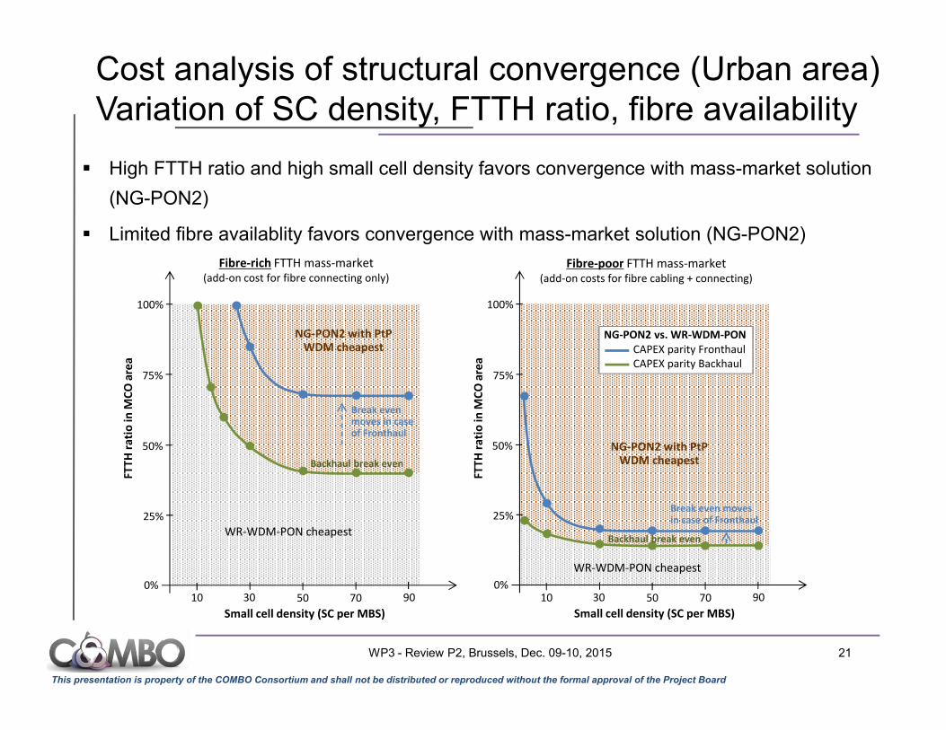
WR-WDM-PON cheapest
50%
Fibre-rich FTTH mass-market (add-on cost for fibre connecting only)
0%
100%
50%
Fibre-poor FTTH mass-market (add-on costs for fibre cabling + connecting)
10 30 50 70 90
Small cell density (SC per MBS)
10 30 50 70 90
25% 25%
75% 75%
WR-WDM-PON cheapest
NG-PON2 vs. WR-WDM-PONCAPEX parity FronthaulCAPEX parity Backhaul
NG-PON2 with PtP WDM cheapest
Break even moves in case of Fronthaul
Backhaul break even
Backhaul break even
FTTH
rat
io in
MC
O a
rea
Break even moves in case of Fronthaul
FTTH
rat
io in
MC
O a
rea
NG-PON2 with PtP WDM cheapest
High FTTH ratio and high small cell density favors convergence with mass-market solution
(NG-PON2)
Limited fibre availablity favors convergence with mass-market solution (NG-PON2)
Cost analysis of structural convergence (Urban area) Variation of SC density, FTTH ratio, fibre availability
WP3 - Review P2, Brussels, Dec. 09-10, 2015 21