Embed Size (px)
Citation preview
IOSR Journal of Mechanical and Civil Engineering (IOSR-JMCE)
ISSN: 2278-1684, PP: 01-06 www.iosrjournals.org
Second International Conference on Emerging Trends in Engineering (SICETE) 1 | Page
Dr.J.J.Magdum College of Engineering, Jaysingpur
Flexible Coupling a New Approach
Prof. R.S.Powar 1 ,Prof. N.S Deshmukh
2, Dr.S.D.Suryawanshi
3,
1( Department of Mechanical Engineering Dr. J. J .Magdum College of Engineering, Jaysingpur (M.S), India)
2,3( Department of Mechanical Engineering SSVPSs BSD College of Engineering Dhule-424005 (M.S), India)
ABSTRACT : This paper presents the concept of flexible type of coupling for power transmission in light load
conditions. In some cases of power transmission due to manufacturing limitations and/or misalignment at the
time of installation, coupling may fail. It is observed that in power transmission flexible links are used in the
form of belt loops. In such a design, belt subjects to shear failure. In present study belts are so mounted on
flanges that it subjects to tensile load. In general it is observed that the strength of material is higher in tension
than shear. In previous design of flexible couplings more axial space and material is required than the present
design. For present coupling various types of belts are to be used as a flexible link in between two shafts.
Various belts are selected and tested for coupling design; with this data of belt testing a flexible coupling is designed. Due to modifications in design and material selection 20 % weight reduction is achieved .This weight
reduction not only reduces cost of coupling but will reduces installation and vibration problems. Radial
distance also decreases by 25%.Connecting two flanges belt as a flexible element is used which reduces noise
during power transmission. It will be used for single cylinder four stroke engines having rated power of 2.28 kW
at 3600 rpm. This set up is being used for I.C. Engine lab. The concept originates due to frequent failure of
rigid flange coupling.
Keyword: flexible Coupling, belt, weight reduction, misalignment, light load
I. INTRODUCTION
A flexible coupling is a device which is use to connect two shafts for power transmission. Coupling Corporation
of America [1] stated Flexible disk or ring pack couplings transmit force from one flange to another by tension
in the rings from the bolts in one flange, to the bolts in opposing flange. The disks are separated from each other
so that there is no sliding or no generation of heat. S.B. Jaiswal, M.D. Pasarkar [2] analyze coupling of
different material which give satisfactory results. As in the analysis the failure occurred along the weld on the
flange side. It is suggested that new material alloy steel can be used for better results. Lovejoy Torsional
Couplings [3] uses highly versatile elastomeric element; that can allow parallel, angular, torsional and axial
misalignment. It can sustain substantial shock and vibration capabilities. According to a technical report of VFD
induced coupling failure [4], was generated for Kop flex KD disc Coupling. This is used to transmit torque and
provide for both angular and axial misalignment. Shafts with a coupling comprised of shaft mounted hubs
connected through flexible disc packs with spacer or sleeve assemblies. This type of couplings uses stainless
steel discs as flexible members, providing high strength and good corrosion resistance for heavy load. Stephen
Jesse, J. Wesley Hines, James Kuropatwinski, Andrew Edmondson, Thomas G. Carley[5], concluded in their
paper that as the misalignment between the shaft increases it shows noticeable increase in the vibration and the
generating temperature.
Literature cited revealed that for light load applications like lab testing setups, small power generator unit
etc. there is scope for design and development of flexible coupling for maintenance free longer life. This type of
coupling should be light, economical, easy to install, maintain and overhaul.
II. METHODOLOGY
The methodology includes use of flexible coupling having hub, flanges, bolts and belt. As the main theme of
this project is to transfer load with the help of belts and flanges various belts were tested for their strengths and
elongation for the various loads. Similarly some changes are made in the design of flange for the modification.
Flexible Coupling a New Approach
Second International Conference on Emerging Trends in Engineering (SICETE) 2 | Page
Dr.J.J.Magdum College of Engineering, Jaysingpur
2.1 Belt Testing
Here in this project stage, 2 belts were tested on UTM (Universal Testing Machine) viz. polyester belt
and nylon belt with the load step of 30 N. When the load was applied on the belts the main problem occurs is of
slipping of belts.
The remedy for this problem is attachments of thick rubber pads. Rubber pads are attached in order to increase
frictional resistance. After this again the test were taken and results are plotted as below:
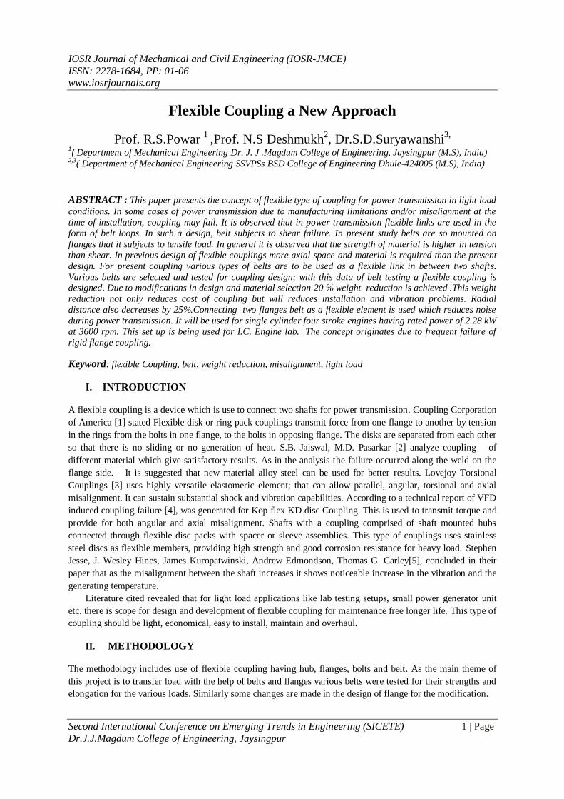
2.1.1 Polyester Power Transmission Belt
Fig. 1 Polyester belt with rubber Pads for testing
The following is the graph plotted for the results obtained on UTM with load step of 30N and for the belt length
as 500 mm without thick rubber pads at the ends. Whereas the average length of rubber pads is 57.5 mm.
Fig. 2 Load Vs Elongation for Polyesters belt
0
2
4
6
8
10
12
14
30 60 90 120 150 180 210 240 270 300 330 360 390 450
Elo
nga
tio
n(m
m)
Load(N)
Load Vs Elongation
Flexible Coupling a New Approach
Second International Conference on Emerging Trends in Engineering (SICETE) 3 | Page
Dr.J.J.Magdum College of Engineering, Jaysingpur
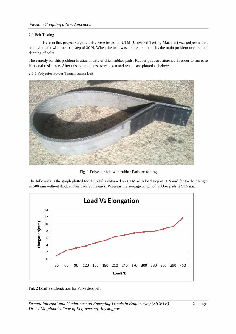
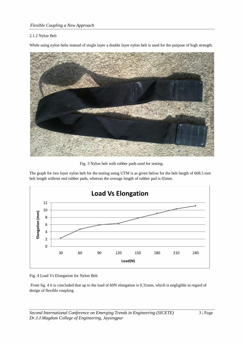
2.1.2 Nylon Belt
While using nylon belts instead of single layer a double layer nylon belt is used for the purpose of high strength.
Fig. 3 Nylon belt with rubber pads used for testing.
The graph for two layer nylon belt for the testing using UTM is as given below for the belt length of 668.5 mm
belt length without end rubber pads, whereas the average length of rubber pad is 65mm.
Fig. 4 Load Vs Elongation for Nylon Belt
From fig. 4 it is concluded that up to the load of 60N elongation is 0.31mm, which is negligible in regard of
design of flexible coupling.
0
2
4
6
8
10
12
30 60 90 120 150 180 210 240
Elo
nga
tio
n (m
m)
Load(N)
Load Vs Elongation
Flexible Coupling a New Approach
Second International Conference on Emerging Trends in Engineering (SICETE) 4 | Page
Dr.J.J.Magdum College of Engineering, Jaysingpur
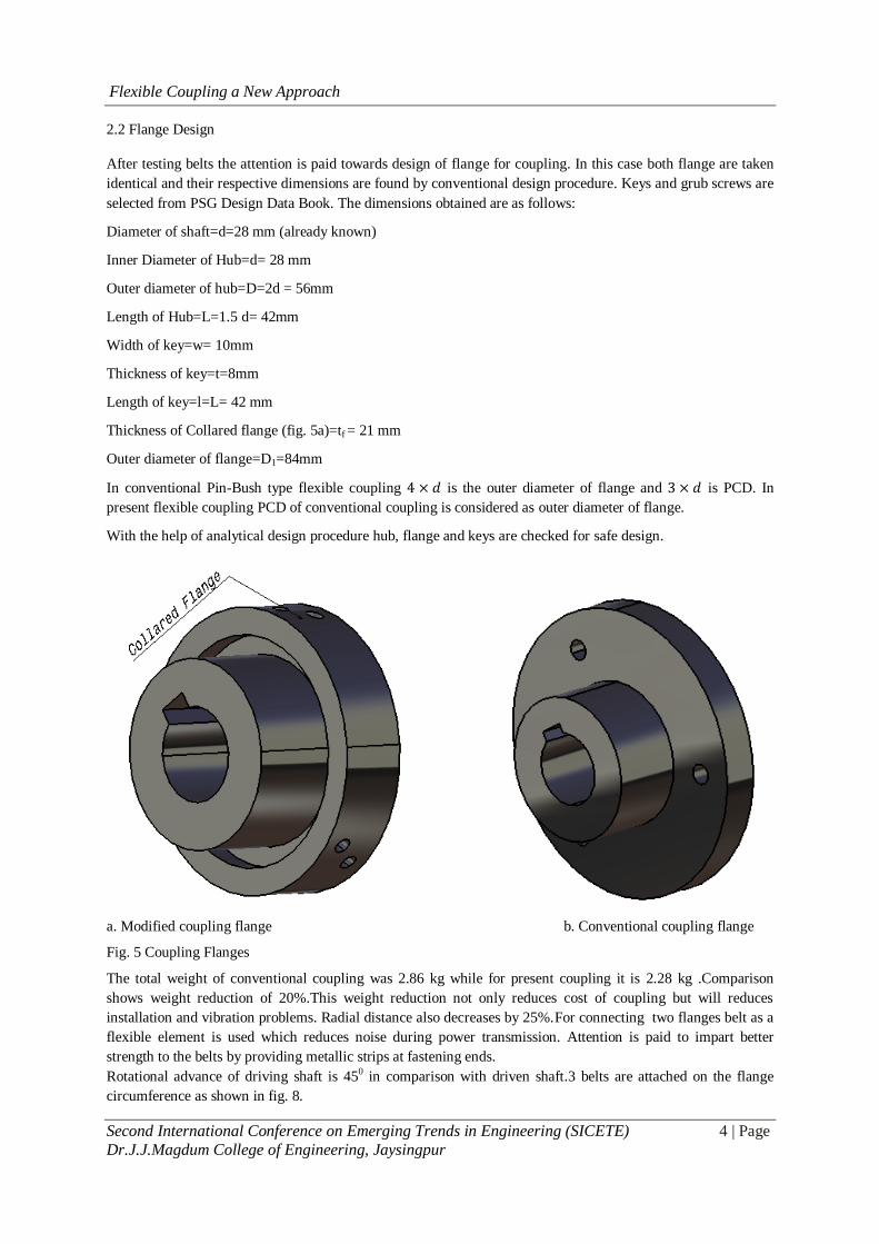
2.2 Flange Design
After testing belts the attention is paid towards design of flange for coupling. In this case both flange are taken
identical and their respective dimensions are found by conventional design procedure. Keys and grub screws are
selected from PSG Design Data Book. The dimensions obtained are as follows:
Diameter of shaft=d=28 mm (already known)
Inner Diameter of Hub=d= 28 mm
Outer diameter of hub=D=2d = 56mm
Length of Hub=L=1.5 d= 42mm
Width of key=w= 10mm
Thickness of key=t=8mm
Length of key=l=L= 42 mm
Thickness of Collared flange (fig. 5a)=tf = 21 mm
Outer diameter of flange=D1=84mm
In conventional Pin-Bush type flexible coupling 4 × 𝑑 is the outer diameter of flange and 3 × 𝑑 is PCD. In
present flexible coupling PCD of conventional coupling is considered as outer diameter of flange.
With the help of analytical design procedure hub, flange and keys are checked for safe design.
a. Modified coupling flange b. Conventional coupling flange
Fig. 5 Coupling Flanges
The total weight of conventional coupling was 2.86 kg while for present coupling it is 2.28 kg .Comparison
shows weight reduction of 20%.This weight reduction not only reduces cost of coupling but will reduces
installation and vibration problems. Radial distance also decreases by 25%.For connecting two flanges belt as a
flexible element is used which reduces noise during power transmission. Attention is paid to impart better
strength to the belts by providing metallic strips at fastening ends.
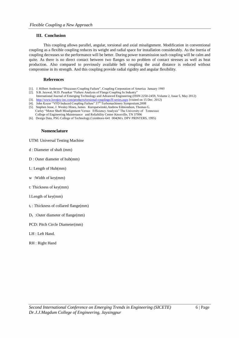
Rotational advance of driving shaft is 450 in comparison with driven shaft.3 belts are attached on the flange
circumference as shown in fig. 8.
Flexible Coupling a New Approach
Second International Conference on Emerging Trends in Engineering (SICETE) 5 | Page
Dr.J.J.Magdum College of Engineering, Jaysingpur
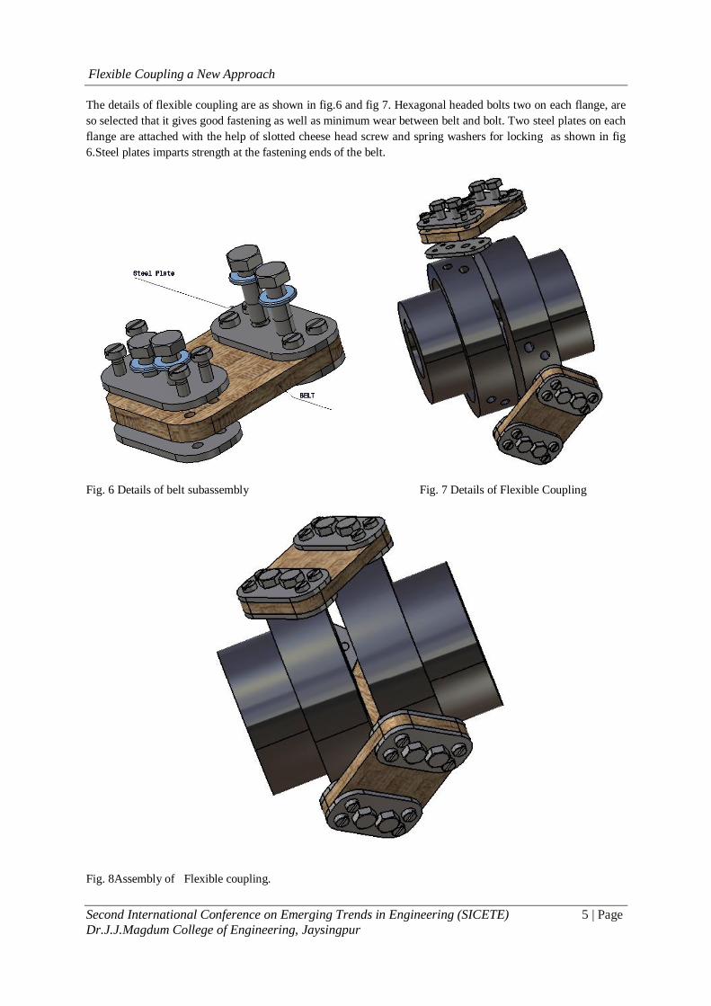
The details of flexible coupling are as shown in fig.6 and fig 7. Hexagonal headed bolts two on each flange, are
so selected that it gives good fastening as well as minimum wear between belt and bolt. Two steel plates on each
flange are attached with the help of slotted cheese head screw and spring washers for locking as shown in fig
6.Steel plates imparts strength at the fastening ends of the belt.
Fig. 6 Details of belt subassembly Fig. 7 Details of Flexible Coupling
Fig. 8Assembly of Flexible coupling.
Flexible Coupling a New Approach
Second International Conference on Emerging Trends in Engineering (SICETE) 6 | Page
Dr.J.J.Magdum College of Engineering, Jaysingpur
III. Conclusion
This coupling allows parallel, angular, torsional and axial misalignment. Modification in conventional
coupling as a flexible coupling reduces its weight and radial space for installation considerably. As the inertia of
coupling decreases so the performance will be better. During power transmission such coupling will be calm and
quite. As there is no direct contact between two flanges so no problem of contact stresses as well as heat
production. Also compared to previously available belt coupling the axial distance is reduced without
compromise in its strength. And this coupling provide radial rigidity and angular flexibility.
References
[1]. J. Hilbert Anderson-“Discusses Coupling Failure”, Coupling Corporation of America January 1985
[2]. S.B. Jaiswal, M.D. Pasarkar “Failure Analysis of Flange Coupling In Industry”
International Journal of Emerging Technology and Advanced Engineering (ISSN 2250-2459, Volume 2, Issue 5, May 2012)
[3]. http://www.lovejoy-inc.com/products/torsional-couplings/lf-series.aspx (visited on 15 Dec. 2012)
[4]. John Kocur “VFD Induced Coupling Failure” 37th Turbomachinery Symposium,2008
[5]. Stephen Jesse, J. Wesley Hines, James Kuropatwinski,Andrew Edmondson, Thomas G.
Carley “Motor Shaft Misalignment Versus Efficiency Analysis” The University of Tennessee
College of Engineering Maintenance and Reliability Center Knoxville, TN 37996
[6]. Design Data, PSG College of Technology,Coimbtore-641 004(M/s. DPV PRINTERS, 1995)
Nomenclature
UTM: Universal Testing Machine
d : Diameter of shaft (mm)
D : Outer diameter of hub(mm)
L: Length of Hub(mm)
w :Width of key(mm)
t: Thickness of key(mm)
l:Length of key(mm)
tf : Thickness of collared flange(mm)
D1 :Outer diameter of flange(mm)
PCD: Pitch Circle Diameter(mm)
LH : Left Hand.
RH : Right Hand