Embed Size (px)
Citation preview
Loughborough UniversityInstitutional Repository
Flexible automaticgeneration control systemfor embedded HVDC links
This item was submitted to Loughborough University's Institutional Repositoryby the/an author.
Citation: GONZALEZ-LONGATT, F., STELIUK, A. and HINOJOSA, V.H.,2015. Flexible automatic generation control system for embedded HVDC links.IEEE PowerTech 2015, Eindhoven, the Netherlands, 29 June - 2 July.
Additional Information:
• Accepted for the PowerTech Eindhoven 2015 conference(http://powertech2015-eindhoven.tue.nl/) c© 2015 IEEE. Personaluse of this material is permitted. Permission from IEEE must beobtained for all other uses, in any current or future media, includingreprinting/republishing this material for advertising or promotionalpurposes, creating new collective works, for resale or redistribution toservers or lists, or reuse of any copyrighted component of this work inother works.
Metadata Record: https://dspace.lboro.ac.uk/2134/17690
Version: Accepted for publication
Publisher: c© IEEE
Rights: This work is made available according to the conditions of the Cre-ative Commons Attribution-NonCommercial-NoDerivatives 4.0 International(CC BY-NC-ND 4.0) licence. Full details of this licence are available at:https://creativecommons.org/licenses/by-nc-nd/4.0/
Please cite the published version.
Flexible Automatic Generation Control System for
Embedded HVDC Links
Francisco Gonzalez-Longatt
Loughborough University School of Electric, Electronic and
Systems Engineering
Loughborough, United Kingdom
Anton Steliuk
DMCC Engineering Ltd Peremogy ave., 56, Kyiv, 03056
Donetsk, Ukraine
Víctor Hugo Hinojosa M Federico Santa María Technical
University Electrical Energy Department Valparaiso-Chile
Abstract— Frequency quality will be maintained as ancillary
service instead of utilities, and different qualities in one system
may be requested depends on the framework of service. This
paper proposes a flexible Automatic Generation Control (AGC)
system for embedded HVDC links in order to provide frequency
sensitive response and control power interchange.
Index Terms-- Automatic generation control, frequency
controller, frequency stability, power system, protection scheme,
wind turbine generator.
I. INTRODUCTION
Future energy systems networks will be completely
different to the power systems on nowadays [1], [2]. High
and low power converters will be massively deployed in
several areas on the electric network [3], [4], [3]: (i)
renewable energy from highly variable generators connected
over high power converters, (ii) several technologies for
energy storage with very different time constants, some of
them using power converters as an interface to the grid, and
(iii) Pan-European transmission network facilitating the
massive integration of large-scale renewable energy sources
and the balancing and transportation of electricity based on
underwater multi-terminal high voltage direct current
transmission. The developments of stronger interconnector
and massive integration of offshore wind power in remote
location are steadily increasing the demand for more robust,
efficient, and reliable grid integration solutions. Multi-
terminal Voltage source converter (VSC)-based HVDC
(MTDC) technology has the potential to increase
transmission capacity, system reliability, and electricity
market opportunities.
The developments of stronger interconnector and massive
integration of offshore wind power in remote location are
steadily increasing the demand for more robust, efficient, and
reliable grid integration solutions. Multi-terminal Voltage
source converter (VSC)-based HVDC (MTDC) technology
has the potential to increase transmission capacity, system
reliability, and electricity market opportunities.
The integration of VSC-HVDC links into transmission
systems has the potential to afford a powerful new tool for
controlling both over and under frequency conditions. The
high degree of controllability inherent to the active power
flow on an HVDC link allows rapid changes to the power
flow to be used to counter active power imbalances [5].
Primary frequency control in HVDC has been a hot topic
in recent times. Several publications has developed and tested
controllers to enable inertial response on HVDC systems [6-
9]. HVDC for primary frequency control has been considered
in several publications [10], [11], and the coordinated
primary frequency control among non-synchronous systems
connected by a multi-terminal high-voltage direct current grid
is studied in [12]. Also, the problem of providing frequency
control services, including inertia emulation and primary
frequency control, from offshore wind farms connected
through a MTDC network has been studied in [13]. However,
secondary and tertiary frequency control considering HVDC
or MTDC systems has deserved a very low attention in recent
publications.
This paper proposes a flexible Automatic Generation
Control (AGC) system for embedded HVDC link in order to
provide frequency sensitive response and control power
interchange.
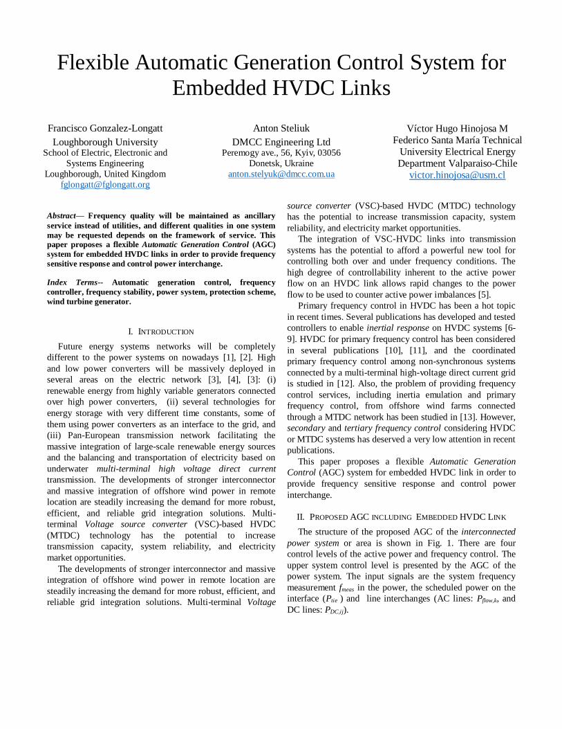
II. PROPOSED AGC INCLUDING EMBEDDED HVDC LINK
The structure of the proposed AGC of the interconnected
power system or area is shown in Fig. 1. There are four
control levels of the active power and frequency control. The
upper system control level is presented by the AGC of the
power system. The input signals are the system frequency
measurement fmeas in the power, the scheduled power on the
interface (Ptie ) and line interchanges (AC lines: Pflow,k, and
DC lines: PDC,ij).
Control
levels
System
Levelfsys
fref Pnet,ref
Area
controller 1
Governor 1,1
AGC of the Area
Area 1 fP1
Governor 1m
DP1mDP11
DPt1mDPt11
PAGC,1
Power
Plant
Level
Generation
Unit
Unit Level
Area
controller 2
Governor nm
Area 2
Governor n1
DPn1 DPmn
DPtn1
Gnm
... ...
PAGC,2
Pflow,1
Pflow,m
f1,1
G11 G1m
...
...
f1,m fn,1
Gn1
DPtnmfn,m
fPn
...
...
PG11 PG1m PG2m PG2m
PDC,ref
PDC,ref
PDC,ij
PDC,ij
...
HVDC
Link
Level
Fig. 1. The structure of the automatic generation control.
Based on tie-line interchanges, the net interchange power
(Pnet,ref) is calculated as:
, , ,
1
branchesN
net ref flow k DC ij
k
P P P
(1)
In the AGC of the power system (at the system control
level) the system frequency deviation (Df) and the changes on
the net interchange power (DPnet) deviations are defined as:
sys reff f fD (2)
,net net net refP P PD (3)
where: fref is a frequency set point value (typically, the rated
or nominal frequency), Pnet.ref is a net interchange power set
point value. The area control error (ACE) is calculated as:
net biasACE P K f D D (4)
where: Kbias is the frequency bias.
In the event of the internal power imbalance of the power
system, ACE defines the power to be compensated by the
regulating power plants and the HVDC link in order to
enforce frequency stabilization between the areas [14]. In the
case of the external frequency disturbance due to the different
signs of frequency and net interchange power deviations ACE
value tends to zero that provides the selectivity of the AGC
operation depending on location of the disturbance [14], [15].
The unscheduled active power setting PAGC formed by the
proportional-integral (PI) controller on basis of is calculated
as follows: 2
1
t
AGC P I
t
P K ACE K ACEdt (5)
where: KP is the proportional gain of the PI controller; KI is
the integral gain of the PI controller; t1, t2 are the integration
limits.
As shown in Fig. 1, the control i-th AGC control signal
PAGCi, is transmitted to each regulating power plant, defined
according to the participation factor αi of individual power
plant in the secondary frequency control:
, αAGC i i AGCP P i = 1, 2, …, n (6)
At the power plant control level the signal PPCi formed by
the power plant PI controller is calculated as: 2
11 1
tm mPC PC
PCi P f agci Tj I f agci Tj
j jt
P K K f P P K K f P P dt
D D D D D D
i = 1, 2, …, n
where: KPPC is the proportional gain of the power plant PI
controller; KIPC is the integral gain of the power plant PI
controller; Kf is the coefficient of frequency correction; and
DPTj is the sum of the turbine power change of the
generating units participating in the secondary frequency
control.
The distribution of the control signal PPCi at the i-power
plant control level is performed in accordance with the
participation factors βij of the generating units of i-power
plant in the secondary frequency control (see Fig. 2):
βij ij PCiP PD i = 1, 2, …, n and j = 1, 2,…,m (7)
where: n is the number of the regulating power plants; m is
the number of the generating units of the i-power plant; ∆Pij
is the control signal from the power plant controller. The
control signal ΔPij.ref is distributed in such a way that:
1
m
PCi ij
j
P P
D i = 1, 2, …, n
and
1 1 1
n n m
agc agci ij
i i j
P P P
D i = 1, 2, …, n
The calculated control signal ΔPij from the power
controller is transmitted to the turbine governor of the
generating unit (aggregate control level) via the speed
changer motor (see Fig. 2). Further, according to the
reference control signal ΔPij, the turbine governor generates a
signal of the turbine power change ΔPtij. Thus, the power
changing of the generating units restores the normal
frequency and scheduled net interchange power.
Frequency quality will be maintained as ancillary service
instead of utilities, and different qualities in one system may
be requested depends on the framework of service.
The AGC is a significant control process that operates
constantly to balance the generation and load in power
systems at a minimum cost. In this paper, the proposed AGC
include a control system to provide signals to embedded
HVDC links in order to provide frequency sensitive response
and control power interchange.
III. SIMULATION AND RESULTS
The IEEE 14 Bus Test Case represents a portion of the
American Electric Power System (in the Midwestern USA) as
of February, 1962. The original IEEE 14-bus system (as
presented on [16], [17]) has been slightly modified, the
system has three Power Plants and a boundary has been
defined to establish 2 operational areas (Area 1 and Area 2 in
Fig. 2). Not depicted in Fig. 2, but included in the system
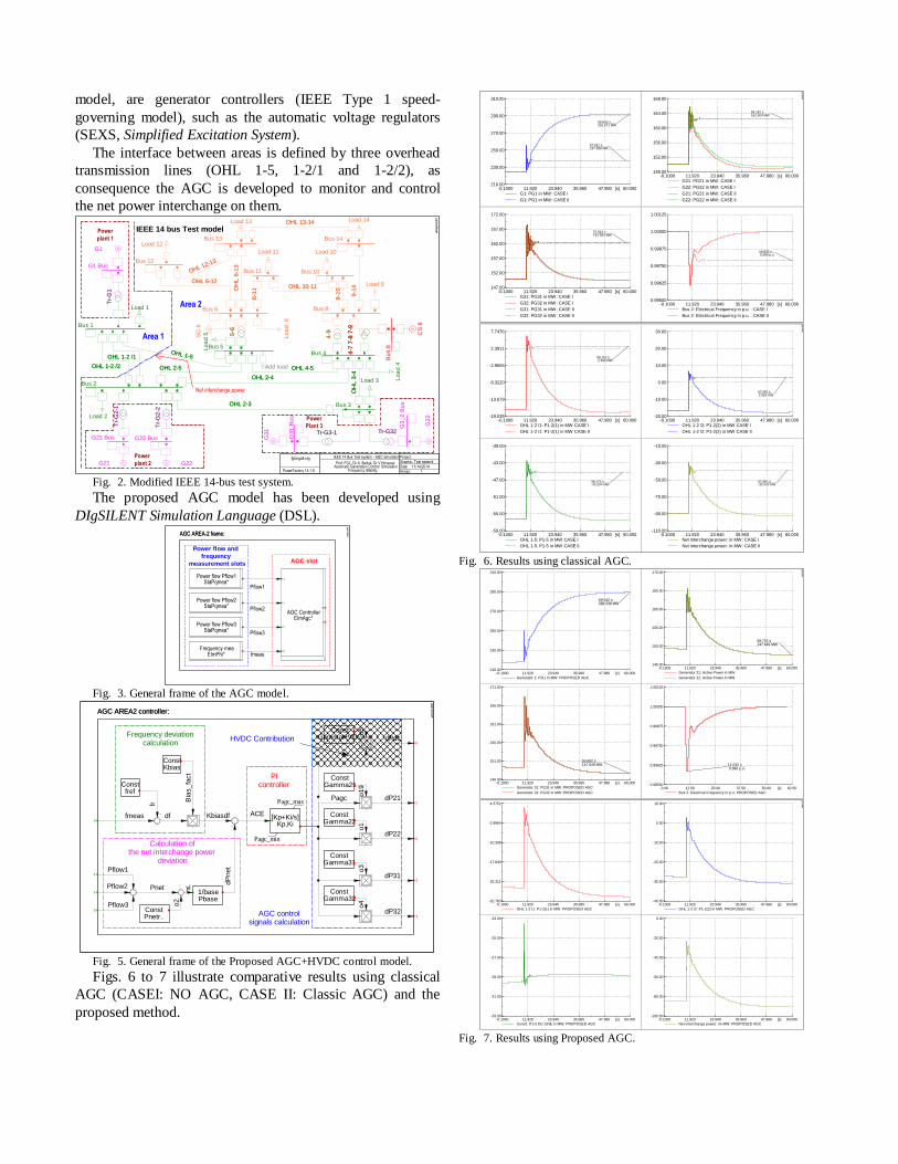
model, are generator controllers (IEEE Type 1 speed-
governing model), such as the automatic voltage regulators
(SEXS, Simplified Excitation System).
The interface between areas is defined by three overhead
transmission lines (OHL 1-5, 1-2/1 and 1-2/2), as
consequence the AGC is developed to monitor and control
the net power interchange on them.
Net interchange power
Area 1
Area 2
Power
Plant 3
Power
plant 2
Power
plant 1
IEEE 14 bus Test model
G3
1 B
us
G21 Bus
G3
_2
Bu
s
G1 Bus
G22 Bus
Bu
s 8
Bus 6
Bus 11 Bus 10
Bus 9
Bus 14Bus 13
Bus 12
Bus 3
Bus 2
Bus 1
Bus 5Bus 4
fglongatt.org
PowerFactory 15.1.6
IEEE 14 Bus Test system - AGC simulation
Prof. FGL, Dr A. Steliuk, Dr V Hinojosa Automatic Generation Control: Simulation
Frequency Stability
Project: Graphic: Test network Date: 11/14/2014 Annex: 1
Load 1
Add load
Tr-G3-1Tr-G3-1
G~
G3
1
Tr-
G2
-1T
r-G
2-1
G~G21
Tr-G32Tr-G32
Tr-
G1
Tr-
G1
Tr-
G2
-2T
r-G
2-2
4-7
7-8
7-9
4-7
7-8
7-9
4-7
7-8
7-9G~
SC
6
G ~G
33
G ~
CS
8
5-6
5-6
4-9
4-9
G~ G22
G~
G1
Load 2
Load 3 Lo
ad
4
Lo
ad
5
OHL 1-5OHL 1-5
OHL 1-2 /2OHL 1-2 /2
OHL 1-2 /1OHL 1-2 /1
OHL 2-5OHL 2-5 OHL 4-5OHL 4-5
OHL 2-4OHL 2-4
OHL 2-3OHL 2-3
OH
L 3
-4O
HL
3-4
Lo
ad
6
Load 9
Load 10Load 11
Load 12
Load 14Load 13
6-1
16
-11 OHL 10-11OHL 10-11
9-1
09
-10
9-1
49
-14
OHL 13-14OHL 13-14
OH
L 6
-13
OH
L 6
-13
OHL 6-12OHL 6-12
OHL 12-13
OHL 12-13
DIg
SIL
EN
T
Fig. 2. Modified IEEE 14-bus test system.
The proposed AGC model has been developed using
DIgSILENT Simulation Language (DSL). AGC AREA-2 frame:
AGC slot
Power flow and
frequency
measurement slots
AGC ControllerElmAgc*
0
1
2
3
0
1
Frequency meaElmPhi*
Power flow Pflow3StaPqmea*
Power flow Pflow2StaPqmea*
Power flow Pflow1StaPqmea*
AGC AREA-2 frame:
fmeas
Pflow3
Pflow2
Pflow1
DIg
SIL
EN
T
Fig. 3. General frame of the AGC model.
AGC AREA2 controller:
HVDC Contribution
Calculation ofthe net interchange power
deviation
Frequency deviationcalculation
AGC control signals calculation
PIcontroller
ConstGammaHVDC
ConstGamma32
ConstGamma31
ConstGamma22
ConstPnetr..
ConstKbias
-
ConstGamma21
[Kp+Ki/s]Kp,Ki
Pagc_max
Pagc_min
Constfref
-
1/basePbase
-
AGC AREA2 controller:
0
2
3
1
1
2
3
4
0dPdc
o5
fmeas
o4
o3
o1
dP
net
yi
o2
Pnet
dP32
dP31
dP22
dP21PagcBia
s_fa
ct
df
fr
o19
ACEKbiasdf
Pflow1
Pflow3
Pflow2
DIg
SIL
EN
T
Fig. 5. General frame of the Proposed AGC+HVDC control model.
Figs. 6 to 7 illustrate comparative results using classical
AGC (CASEI: NO AGC, CASE II: Classic AGC) and the
proposed method.
60.00047.98035.96023.94011.920-0.1000 [s]
310.00
290.00
270.00
250.00
230.00
210.00
G1: PG1 in MW: CASE I
G1: PG1 in MW: CASE II
57.912 s237.388 MW
59.662 s291.671 MW
60.00047.98035.96023.94011.920-0.1000 [s]
168.00
164.00
160.00
156.00
152.00
148.00
G21: PG21 in MW: CASE I
G22: PG22 in MW: CASE I
G21: PG21 in MW: CASE II
G22: PG22 in MW: CASE II
56.182 s162.500 MW
60.00047.98035.96023.94011.920-0.1000 [s]
172.00
167.00
162.00
157.00
152.00
147.00
G31: PG31 in MW: CASE I
G32: PG32 in MW: CASE I
G31: PG31 in MW: CASE II
G32: PG32 in MW: CASE II
57.912 s162.500 MW
60.00047.98035.96023.94011.920-0.1000 [s]
1.00125
1.00000
0.99875
0.99750
0.99625
0.99500
Bus 2: Electrical Frequency in p.u. : CASE I
Bus 2: Electrical Frequency in p.u. : CASE II
59.832 s 0.998 p.u.
DIg
SIL
EN
T
60.00047.98035.96023.94011.920-0.1000 [s]
30.00
20.00
10.00
0.00
-10.00
-20.00
OHL 1-2 /2: P1-2(2) in MW CASE I
OHL 1-2 /2: P1-2(2) in MW CASE II
57.092 s 2.926 MW
60.00047.98035.96023.94011.920-0.1000 [s]
7.7476
2.3911
-2.9655
-8.3220
-13.679
-19.035
OHL 1-2 /1: P1-2(1) in MW CASE I
OHL 1-2 /1: P1-2(1) in MW CASE II
59.152 s 2.938 MW
60.00047.98035.96023.94011.920-0.1000 [s]
-39.00
-43.00
-47.00
-51.00
-55.00
-59.00
OHL 1-5: P1-5 in MW CASE I
OHL 1-5: P1-5 in MW CASE II
56.172 s-45.204 MW
60.00047.98035.96023.94011.920-0.1000 [s]
-10.00
-30.00
-50.00
-70.00
-90.00
-110.00
Net interchange power: in MW: CASE I
Net interchange power: in MW: CASE II
57.562 s-39.340 MW
DIg
SIL
EN
T
Fig. 6. Results using classical AGC.
60.00047.98035.96023.94011.920-0.1000 [s]
310.00
290.00
270.00
250.00
230.00
210.00
Generator 1: PG1 in MW: PROPOSED AGC
59.542 s289.238 MW
60.00047.98035.96023.94011.920-0.1000 [s]
170.00
165.00
160.00
155.00
150.00
145.00
Generator 21: Active Power in MW
Generator 22: Active Power in MW
59.702 s147.649 MW
60.00047.98035.96023.94011.920-0.1000 [s]
171.00
166.00
161.00
156.00
151.00
146.00
Generator 31: PG31 in MW: PROPOSED AGC
Generator 32: PG32 in MW: PROPOSED AGC
59.682 s147.649 MW
62.5050.0037.5025.0012.500.00 [s]
1.00125
1.00000
0.99875
0.99750
0.99625
0.99500
Bus 2: Electrical Frequency in p.u: PROPOSED AGC
11.032 s 0.996 p.u.
DIg
SIL
EN
T
60.00047.98035.96023.94011.920-0.1000 [s]
10.00
0.00
-10.00
-20.00
-30.00
-40.00
OHL 1-2 /2: P1-2(2) in MW: PROPOSED AGC
60.00047.98035.96023.94011.920-0.1000 [s]
4.5752
-2.8964
-10.368
-17.840
-25.311
-32.783
OHL 1-2 /1: P1-2(1) in MW: PROPOSED AGC
60.00047.98035.96023.94011.920-0.1000 [s]
-23.00
-25.00
-27.00
-29.00
-31.00
-33.00
Conv2: P1-5 DC-LINE in MW: PROPOSED AGC
60.00047.98035.96023.94011.920-0.1000 [s]
0.00
-20.00
-40.00
-60.00
-80.00
-100.00
Net interchange power: im MW: PROPOSED AGC
DIg
SIL
EN
T
Fig. 7. Results using Proposed AGC.
IV. REFERENCES
[1] F. Gonzalez-Longatt, "Frequency Control and Inertial Response
Schemes for the Future Power Networks," in Large Scale Renewable
Power Generation, J. Hossain and A. Mahmud, Eds., ed: Springer
Singapore, 2014, pp. 193-231.
[2] F. Gonzalez-Longatt, "Frequency Control and Inertial Response
Schemes for the Future Power Networks," in Advances in Technologies for Generation, Transmission and Storage, Green Energy and
Technology Series. vol. VIII, J. Hossain and A. Mahmud, Eds., ed
Singapur: Springer-Verlag, 2014, p. 363.
[3] F. Gonzalez-Longatt, "TUTORIAL: Frequency Control and Inertia
Response Schemes for the Future Power Networks," presented at the
IEEE Inernational Energy Conference and Exhibition, ENERGYCON
2012, Florence, Italy, 2012.
[4] F. Gonzalez-Longatt, "Impact of synthetic inertia from wind power on
the protection/control schemes of future power systems: Simulation
study," in Developments in Power Systems Protection, 2012. DPSP
2012. 11th International Conference on, 2012, pp. 1-6.
[5] P. Wall, "Online Prediction of the Post-Disturbance Frequency
Behaviour of a Power System," Doctor of Philosophy, School of
Electrical and Electronic Engineering, The University of Manchester,
Manchester, UK, 2013.
[6] Z. Jiebei, C. D. Booth, G. P. Adam, and A. J. Roscoe, "Inertia
emulation control of VSC-HVDC transmission system," in Advanced
Power System Automation and Protection (APAP), 2011 International Conference on, 2011, pp. 1-6.
[7] Z. Jiebei, C. D. Booth, G. P. Adam, A. J. Roscoe, and C. G. Bright,
"Inertia Emulation Control Strategy for VSC-HVDC Transmission
Systems," Power Systems, IEEE Transactions on, vol. 28, pp. 1277-
1287, 2013.
[8] Z. Jiebei, J. M. Guerrero, C. D. Booth, Z. Haotian, and G. P. Adam, "A
generic Inertia Emulation Controller for multi-terminal VSC-HVDC
systems," in Renewable Power Generation Conference (RPG 2013),
2nd IET, 2013, pp. 1-6.
[9] Y. Phulpin, "Communication-Free Inertia and Frequency Control for
Wind Generators Connected by an HVDC-Link," Power Systems, IEEE Transactions on, vol. 27, pp. 1136-1137, 2012.
[10] G. Fujita, G. Shirai, and R. Yokoyama, "Automatic generation control
for DC-link power system," in Transmission and Distribution
Conference and Exhibition 2002: Asia Pacific. IEEE/PES , 2002, pp.
1584-1588 vol.3.
[11] P. F. de Toledo, P. Jiuping, K. Srivastava, W. WeiGuo, and H. Chao,
"Case Study of a Multi-Infeed HVDC System," in Power System Technology and IEEE Power India Conference, 2008. POWERCON
2008. Joint International Conference on, 2008, pp. 1-7.
[12] J. Dai, Y. Phulpin, A. Sarlette, and D. Ernst, "Coordinated primary
frequency control among non-synchronous systems connected by a
multi-terminal high-voltage direct current grid," Generation,
Transmission & Distribution, IET, vol. 6, pp. 99-108, 2012.
[13] B. Silva, C. L. Moreira, L. Seca, Y. Phulpin, and J. A. Peas Lopes,
"Provision of Inertial and Primary Frequency Control Services Using
Offshore Multiterminal HVDC Networks," Sustainable Energy, IEEE Transactions on, vol. 3, pp. 800-808, 2012.
[14] V. Pavlovsky and A. Steliuk, "Modelling of automatic generation
control in power systems," in PowerFactory Applications for Power
System Analysis. vol. 1, F. M. Gonzalez-Longatt, Luis Rueda, Jose
(Eds.), Ed., First Edition ed: Springer, 2014, p. 582.
[15] P. Kundur, N. J. Balu, and M. G. Lauby, Power system stability and
control. New York: McGraw-Hill, 1994.
[16] F. Milano, Power system modelling and scripting. London: Springer,
2010.
[17] F. Gonzalez-Longatt. (2014). IEEE 14 bus Test: Power system test case
archive. Available: http://fglongatt.org/OLD/Test_Case_IEEE_14.html