Embed Size (px)
Citation preview

Flexi 7.6 Output on the Gerber EDGE
Scanvec Amiable, Inc. 2 International Plaza, Suite 625 Philadelphia, PA 19113-1518
USA 610-521-6300
www.scanvecamiable.com
© 2005 Scanvec Amiable, Inc. ii
Contents Introduction .......................................................................................... 1
Relevant Features of Flexi 7.6......................................................... 1 Installation............................................................................................ 2
Hardware Setup............................................................................... 2 Using a USB to Parallel Adapter.................................................. 2 Setting Up for Virtual Hybrid Output............................................. 2
Software Setup ................................................................................ 2 Creating a Gerber EDGE Setup in Flexi Production Manager..... 2 Creating a Gerber Cutter Setup in Flexi Production Manager ..... 3
Designing Jobs for the Gerber EDGE.................................................. 4 Using Gerber Omega Workspace Emulation................................... 4 Importing Gerber File Formats......................................................... 4 Exporting to Gerber File Formats .................................................... 4 Basic Composition ........................................................................... 4
Minimizing Print Time................................................................... 4 Working with Color Tables............................................................... 5
Opening a Color Table................................................................. 5 Closing a Color Table .................................................................. 6 Docked or Floating Color Tables ................................................. 6 Changing the View of a Color Table ............................................ 6 Working with Multiple Foil Types ................................................. 6 Working with Third Party Ribbons................................................ 6 Creating New Color Tables.......................................................... 7 Saving a Color Table to a File...................................................... 7 Adding Colors to a Color Table.................................................... 7 Copying a Color to Another Color Table ...................................... 7
Working with Spectratone Colors .................................................... 8 Creating Duotone Colors with the Color Mixer............................. 8
Printing Color Swatches .................................................................. 8 Advanced Settings for Duotone Swatch Tables........................... 9 Advanced Settings for CMYK Swatch Tables.............................. 9 Advanced Settings for Current Palette Swatch Tables ................ 9
Creating Gradients with Spot Colors ............................................. 10 Adding a Gradient to a Color Table ........................................... 11
Using the Underbase Effect........................................................... 12 Creating a Solid Underbase....................................................... 12 Creating a Variable Underbase.................................................. 12 Removing an Underbase ........................................................... 12 Separating an Underbase From the Objects It Was Based On . 12 Making a Vector Object into an Underbase ............................... 13
Using the Finisher Effect ................................................................13 Creating a Rectangular Finish....................................................13 Creating a Shape Finish.............................................................13 Removing a Finish......................................................................13
Using Color Trapping .....................................................................14 Applying Color Trapping to Objects............................................14 Adjusting Color Trapping Using DesignCentral ..........................14
Using Auto-Serialization.................................................................14 Creating Contour Cuts....................................................................15
Creating a Contour Cut with the Contour Effect .........................15 Changing a Vector Object into a Contour Cut ............................16
Outputting Jobs on the Gerber EDGE................................................17 Outputting Virtual Hybrid Jobs........................................................17 Sending the Job to Production Manager using the RIP and Print Dialog .............................................................................................17
Printing on Transparent Materials ..............................................20 Ignoring Overprinting..................................................................20 Outputting Jobs as Process Color..............................................20 Setting Contour Cut Options ......................................................21
Outputting Jobs in Production Manager .........................................25 Selecting Jobs ............................................................................25 Deleting Jobs..............................................................................25 Moving jobs to a Different Output Device...................................25 Sending Jobs to Output Devices ................................................25 Sending the Contour Cut from a Virtual Hybrid Job ...................25
Appendix A: Troubleshooting Issues..................................................26 Hardware Key Issues .....................................................................26
Removing the Aladdin Hardware Key Driver ..............................26 Configuring the Aladdin Driver for USB or LPT Only..................26 Removing the Rainbow Hardware Key Driver(s)........................27 Configuring the Rainbow Drivers for LPT Only ..........................27 Reinstallation Issues ..................................................................27
Using Flexi and Gerber Omega on the Same System (Warp 9 Driver Issue) ...................................................................................28 Configuring Serial Ports for Gerber Cutters ...................................31

© 2005 Scanvec Amiable, Inc. 1
Introduction This guide is intended to help the Flexi user to work with the unique demands and abilities of the Gerber EDGE printers.
Relevant Features of Flexi 7.6 The following features are especially useful for Gerber EDGE users.
Workspace Emulation Workspace emulation rearranges the menus in Flexi so that they resemble the arrangement of menus in other applications such as Gerber Omega. This helps users of those applications to begin to use Flexi.
File Import/Export Flexi is able to import and export many graphic file formats, including Gerber .PLT and .GCA files.
Virtual Hybrid Output A number of output devices exist that can both print an image and cut a contour on it. These are known as hybrid devices. You can get the same results in Flexi by printing a job on the Gerber EDGE, then loading the printed output into a Gerber cutter and cutting it. This is known as virtual hybrid output.
Color Tables Flexi collects all of the colors associated with each type of ink or foil into a separate toolbar called a color table.
You can have multiple color tables open at any given time. You can also create new color tables as needed.
Spectratone Color Support Spectratone colors are supported using the duotone feature, which allows you to specify colors made up of a combination of a base color and a top color.
Spot Color Gradient Support Flexi allows you to create gradients using either process colors, spot colors or duotone colors.
Underbase and Finisher Effects Flexi makes it easy to print both an underbase (primer) that goes beneath a job, and a protective finish that goes on top of a job.
Auto-Serialization Auto-Serialization allows you to create multiple copies of an object, each of which contains a unique number or text. This is ideal for creating product serial number labels, parking lot passes, or name tags.
Supercell Halftoning Supercell halftoning produces halftones that have four times the shades of gray at the same resolution compared to standard algorithms. This creates smoother images when printing angled screens.
Spot Color Mapping and Remapping Flexi’s spot color mapping features allow you to control exactly which foils will be used to print the various colors in your job. Flexi also allows you to remap the colors in an existing job to the spot colors of your choice.

© 2005 Scanvec Amiable, Inc. 2
Installation
Hardware Setup
Using a USB to Parallel Adapter If you are using the Gerber EDGE with a Macintosh, it is necessary to connect to the printer using a USB-to-parallel adapter cable. USB-to-parallel cables are also supported under Windows. We support Scanvec Amiable’s USB-to-parallel adapter on both Macintosh and Windows, as well as Gerber, Belkin and Keyspan.
If you are using a Macintosh, do not connect the USB to parallel adapter to the USB port located on your computer’s keyboard. The USB hub built into the keyboard does not provide enough power to drive a USB adapter cable. Use the USB ports built into your computer’s case instead.
Setting Up for Virtual Hybrid Output Flexi’s virtual hybrid output allows you to print a job on the Gerber EDGE, then loading the printed output into a Gerber cutter and cut contours on it. This provides similar results to a hybrid printer/cutter device. It is possible to connect both printer and cutter to the same computer at the same time. On a PC, you simply connect the printer to the parallel port and the cutter to a serial port. On a Macintosh, or a PC with USB ports, both devices can be connected using USB-to-parallel and USB-to-serial adapter cables.
Software Setup
Creating a Gerber EDGE Setup in Flexi Production Manager
To create a setup for the Gerber EDGE in Production Manager: 1. From the Setup menu, select Add Setup or Change
Setup.
2. Select Color Printers. 3. Under Manufacturer, select Gerber. 4. Under Model Name, select your device model. 5. Click Next.

© 2005 Scanvec Amiable, Inc. 3
6. Edit the Setup name of the device.
The Setup name is the name that will appear in the software for this setup. It can be anything you want. If you have more than one of the same model device, use this name to distinguish between them.
7. Click Next. 8. Select the Port the output device uses for communication.
• For a Parallel Port setup under Windows, select the LPT port, typically LPT1. Make sure that the Use standard LPT driver box is not checked.
The Use Standard LPT Driver box, if checked, forces the software to use the standard Windows LPT driver instead of the high-performance Warp 9 driver. For the Gerber Edge, you should always use the Warp 9 driver, otherwise data may not be transmitted rapidly enough, and banding may result.
• For a setup using a USB to parallel adapter cable, select the port for the USB to parallel adapter cable. The name of this port will vary according to the manufacturer of the adapter cable.
9. Click Finish.
Creating a Gerber Cutter Setup in Flexi Production Manager
To create a setup for a Gerber cutter in Flexi Production Manager: 1. From the Setup menu, select Change Setup or Add
Setup.
2. Select Vinyl cutters. 3. Under Manufacturer, select Gerber. 4. Under Model Name, select your cutter model. 5. Click Next.
6. Edit the Setup name of the device.
The Setup name is the name that will appear in the software for this setup. It can be anything you want. If you have more than one of the same model device, use this name to distinguish between them.
7. Click Next. 8. Select the Port the output device uses for communication.
For a setup using a USB to serial adapter cable, select the port for the USB to serial adapter cable. The name of this port will vary according to the manufacturer of the adapter cable.
9. Click Finish.

© 2005 Scanvec Amiable, Inc. 4
Designing Jobs for the Gerber EDGE
Using Gerber Omega Workspace Emulation Workspace emulation changes the Flexi user interface so that its menus, keyboard shortcuts and toolbars resemble those in other applications such as Gerber Omega. This helps users of those applications to begin to use Flexi. To emulate the Gerber Omega workspace, from the File menu, select Workspace, then Omega.
Importing Gerber File Formats The following Gerber file formats can be imported into Flexi:
• Gerber Omega 2.0 and 1.56 PLT
• Gerber Graphics Advantage 6.20 PLT
• Gerber Clip Art GCA The following features of the Gerber file formats are supported:
Preview Supported. Preview is shown in the Open and Import dialogs.
Paths Supported.
Groups All objects are automatically grouped after import.
Bitmap Supported. If the original bitmap is missing, you will be prompted to locate the file.
Text Text is usually imported as outlines, but in some cases they will be detected as text and you will be prompted for font substitution if there are any missing fonts.
Foil Color Supported. Spot, Spectratone (Duotone), RGB and CMYK are all supported.
Vinyl Color Supported, but if the job contains both both vinyl and foil colors then the following message will appear:
Check Import vinyl data as contour cut and click OK to import vinyl color objects as contour cut paths. If the Import vinyl data as contour cut box is cleared, vinyl objects will be imported as standard vector objects.
Gradients Supported. Linear and radial gradient are supported for both spot and process.
Job print order Supported. Choose "Apply print order" during import to use the job print order.
Overlap/Overprint Supported. Both import as overprint, but heat setting can be changed in driver options.
Primer Supported.
Substrate color Supported. In order to see the substrate color use Open. It is skipped when using Import.
Stroke Color Supported. If the fill and stroke have different primer/overprint or if the stroke is behind the fill then they will be imported as two objects, one with fill only, the other with stroke only.
Exporting to Gerber File Formats The Gerber file format supported for export is the Gerber Art Definition format (.GAD), version 1.0.
Basic Composition The following guidelines will help you lay out your print jobs in a more efficient manner.
Minimizing Print Time The thing that will help minimize your print time the most is to reduce the number of passes needed to the bare minimum. Things that add extra passes to the print job include:

© 2005 Scanvec Amiable, Inc. 5
• Adding additional spot colors to the design.
• Printing process colors when only spot colors are needed.
• Overprinting. Each overprinted color must be printed as an extra pass with a higher heat setting.
Working with Color Tables In Flexi, every type of foil is represented by a color table, which lists all of the colors available for that type of foil.
Opening a Color Table In order to use a color of foil in your design, you must first open the color table for that type of foil. To open a color table: 1. Access the Open dialog using one of the following
methods:
• From the View menu, select Color then Open Table.
• Right-click on the default color table (or any other open color table) and select Open Table.
2. Browse to the Swatch/Library subfolder of the software
installation folder.
3. Select the manufacturer of the foil type (such as Gerber
Scientific Products) and click Open.
4. Select the swatch library for the desired type of foil and
click Open. The selected color table will appear below the default color table.

© 2005 Scanvec Amiable, Inc. 6
Closing a Color Table To close a color table, right-click on the table and select Close.
Docked or Floating Color Tables By default, color tables are docked just above the status bar in the lower part of the screen. To make a color table free-floating, click and drag it out of its position. To return a table to the docked position, drag it back down onto the status bar. You can also double-click on the title bar to dock a color table.
On the Macintosh, all color tables are free-floating and cannot be docked.
Changing the View of a Color Table Each color table has two different views that it can display:
• Palette view displays all of the colors in the table as color swatches.
• List view displays a list of all of the colors, along with their
name, vendor, type and part number.
To switch between views, right-click on the color table and select Palette view or List view.
List view is only available when a color table is free-floating. Switching a docked table to list view will make that table free-floating.
Working with Multiple Foil Types To use multiple foil types in a design, open the color tables for each of the foil types and apply colors from each table as desired.
Working with Third Party Ribbons Each ribbon manufacturer has a folder in the Swatch/Library subfolder of the software installation folder. For instance: Swatch/Library/Gerber Scientific Products
Swatch/Library/Iimak
Swatch/Library/ZeroNine
To use a third party ribbon, open the folder for that manufacturer and select the color table for that type of foil.
The color tables for Gerber foils all have names that begin with Foil, except for the Spectratone table, which is Spectratone.slb.

© 2005 Scanvec Amiable, Inc. 7
Creating New Color Tables To create a new, empty color table, do one of the following:
• From the View menu, select Color then New Table.
• Right-click on the default color table (or any other open color table) and select New Table.
If you create a new color table then try to exit the app without saving it, you will be prompted to save the table to a file.
Saving a Color Table to a File To save a color table to a file: 1. Open the Save As dialog using one of the following
methods:
• Right-click on the table and select Save Table As.
• From the View menu, select Color then Save Table As. Select the table you want to save and click OK.
2. Select the folder you want to save the table in. 3. Enter a filename for the table and click OK.
Adding Colors to a Color Table To add colors to a color table: 1. Open the Color Specs dialog using one of the following
methods:
• From the View menu, select Color then Color Specs.
• Right-click on the color table and select Color Specs.
2. Select the table you want to add colors to from the list at
the top of the dialog. 3. For each color you want to add, do the following:
a. Click New. b. Type a name for the color under Name. c. Select the color Mode.
If you are creating a spot color, select RGB color mode first, and enter the RGB values that will be used to display the spot color. Then change the color mode to Spot.
d. Specify the color values by entering them in the fields to the right, or by clicking in the color bar underneath the list of colors.
4. When finished, click OK.
After adding colors to a color table, remember to save the color table in order to preserve your changes.
Copying a Color to Another Color Table To copy a color from one color table to another, click on the color swatch and drag it into the other table.

© 2005 Scanvec Amiable, Inc. 8
Working with Spectratone Colors Spectratone colors can be created using the duotone feature of Flexi 7.6. The top color of a Duotone color is automatically printed using the Overprint heat setting. Duotone colors can be created using either the Color Mixer or Color Specs dialogs. Any two spot colors can be combined into a duotone color. A shade percentage can be set which will apply to both base and top colors.
Creating Duotone Colors with the Color Mixer 1. From the View menu, select Color Mixer.
2. Select Duotone from the list of color modes.
3. Select the Top and Base colors.
You will only be able to select colors from the color tables that are currently open.
4. Select the percent coverage. This will apply to both top and base colors.
5. Drag the color from the upper left box in the Color Mixer down into a color table.
6. Save the color table.
Printing Color Swatches Users can create sample files that include all possible duotone colors (based on inventory), all swatches, or all CMYK colors. These swatches can then be printed to verify output color, or used to design. Flexi has the ability to automatically create the following types of swatch tables:
Duotone This swatch table shows all of the duotone colors that can be created using the spot colors in your current palette.
CMYK This swatch table shows all of the CMY
color combinations currently available, plus the range of black values.
Current Palette
This swatch table is a listing of all the colors in your current palette.
To create a swatch table: 1. From the View menu, select Create Swatch, then either
Duotone, CMYK or Current Palette. 2. Adjust the following settings in DesignCentral:
Drag

© 2005 Scanvec Amiable, Inc. 9
The size of each swatch.
The amount of space taken up by the labels above and to the left of the swatch table.
The horizontal spacing between swatches.
The vertical spacing between swatches.
The number of swatches or sets of swatches per row.
3. Click Advanced to set advanced settings.
When printing Duotone or Current Palette swatches on the Gerber Edge, always use the Advanced settings to reduce the number of colors being used to the smallest number possible. This will greatly reduce the time and ribbon needed to output the swatches.
4. Click Apply. The swatch table will appear in the lower left corner of the page.
Advanced Settings for Duotone Swatch Tables
On the Color tab, toggle the icon to the left of the spot color listings to determine whether the color will show up in the swatch table. You can exclude colors from either the set of top colors, or the set of base colors.
The color will appear in the swatch table.
The color will not appear in the swatch table.
On the Label tab, select the font to be used for the labels.
Advanced Settings for CMYK Swatch Tables
On the cmyk tab, enter the following settings:
Step The change in ink values between one swatch and the next.
Start The lower boundary of the range of color values in the swatch table.
End The upper boundary of the range of color values in the swatch table. On the Label tab, select the font to be used for the labels.
Advanced Settings for Current Palette Swatch Tables
On the Color tab, toggle the icon to the left of the spot color listings to determine whether the color will show up in the swatch table.
The color will appear in the swatch table.
The color will not appear in the swatch table.

© 2005 Scanvec Amiable, Inc. 10
On the Label tab, select the font to be used for the labels.
Creating Gradients with Spot Colors Spot colors used in gradients may be either conventional spot colors, or duotone colors. Duotone colors used in double spot color gradients may specify different shades of coverage for the top and base colors at both the start and end points. The top color in a two-color gradient will automatically be printed using overprinting (see output section for details). To apply a spot color gradient fill to an object: 1. Select the object. 2. In the Fill/Stroke Editor, select Gradient Fill.
3. Select the type of gradient applied to the object from the
list. The following types are available:
Linear
Radial
Conical
Square
4. Select the gradient color mode from the list. The following modes are available:
RGB The colors in the gradient will all be defined using the RGB color model.
CMYK The colors in the gradient will all be defined
using the CMYK color model.
Single spot color
The gradient will blend between two or more shades of a single spot color.
Double spot colors
The gradient will use two spot colors. This type of gradient is defined solely by its end points: it has no intermediate points in the middle.
5. Open the color tables you want to use colors from. 6. Click Advanced.
7. Adjust the angle of the gradient in the field. 8. To add an intermediate point, click on the spot in the color
bar where you want the point to appear. 9. To edit the position of a point, drag it left or right in the
color bar, or edit the Position field, which ranges from 0% to 100%.
10. To adjust the colors in the gradient: a. Select the end point or intermediate point you want to
change the color at. b. Select the new color from the lower of the two lists. c. Edit the Shade of the color to determine the percent
coverage it will have at that point. 11. Click OK. For example, to create a gradient that is an orange gradient over a solid yellow: 1. Click on the Advanced button to open the Advanced
Settings dialog. 2. Select a double spot color gradient.

© 2005 Scanvec Amiable, Inc. 11
3. Select the Base icon on the right side of the gradient bar. 4. Select the yellow spot color you want to use for the base
from the lower list. 5. Set the base shade to 100%. 6. Set the top shade to whatever percentage you want the
top orange gradient to be at the right edge of the gradient. 7. Select the Top icon on the left side of the gradient bar. 8. Select the orange spot color you want to use for the top
shade from the lower list. 9. Set the top shade to whatever percentage you want the
top orange gradient to be at the left edge of the gradient. 10. Set the base shade to 100%. 11. Click OK.
Adding a Gradient to a Color Table To add a gradient to a color table: 1. Select an object filled with the gradient. 2. Drag the gradient out of the Fill/Stroke editor down into the
table.
3. Save the color table.
© 2005 Scanvec Amiable, Inc. 12
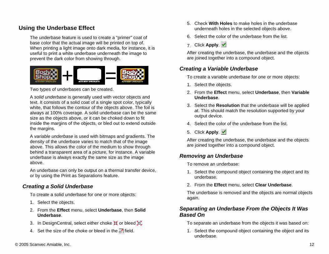
Using the Underbase Effect The underbase feature is used to create a “primer” coat of base color that the actual image will be printed on top of. When printing a light image onto dark media, for instance, it is useful to print a white underbase underneath the image to prevent the dark color from showing through.
+ =
Two types of underbases can be created. A solid underbase is generally used with vector objects and text. It consists of a solid coat of a single spot color, typically white, that follows the contour of the objects above. The foil is always at 100% coverage. A solid underbase can be the same size as the objects above, or it can be choked down to fit inside the margins of the objects, or bled out to extend outside the margins. A variable underbase is used with bitmaps and gradients. The density of the underbase varies to match that of the image above. This allows the color of the medium to show through behind a transparent area of a picture, for instance. A variable underbase is always exactly the same size as the image above. An underbase can only be output on a thermal transfer device, or by using the Print as Separations feature.
Creating a Solid Underbase To create a solid underbase for one or more objects: 1. Select the objects. 2. From the Effect menu, select Underbase, then Solid
Underbase. 3. In DesignCentral, select either choke or bleed . 4. Set the size of the choke or bleed in the field.
5. Check With Holes to make holes in the underbase underneath holes in the selected objects above.
6. Select the color of the underbase from the list.
7. Click Apply. After creating the underbase, the underbase and the objects are joined together into a compound object.
Creating a Variable Underbase To create a variable underbase for one or more objects: 1. Select the objects. 2. From the Effect menu, select Underbase, then Variable
Underbase. 3. Select the Resolution that the underbase will be applied
at. This should match the resolution supported by your output device.
4. Select the color of the underbase from the list.
5. Click Apply. After creating the underbase, the underbase and the objects are joined together into a compound object.
Removing an Underbase To remove an underbase: 1. Select the compound object containing the object and its
underbase. 2. From the Effect menu, select Clear Underbase. The underbase is removed and the objects are normal objects again.
Separating an Underbase From the Objects It Was Based On
To separate an underbase from the objects it was based on: 1. Select the compound object containing the object and its
underbase.

© 2005 Scanvec Amiable, Inc. 13
2. From the Effect menu, select Separate Underbase. The underbase becomes a separate object, and the objects it was based on become normal objects again.
Making a Vector Object into an Underbase To make a vector object into an underbase: 1. Select the object. 2. From the Arrange menu, select Underbase, then Make
Underbase.
3. Select the color of the underbase from the list and click
OK.
Releasing an Underbase Back to a Vector Object To change an underbase made from a vector object back into a vector object: 1. Select the object. 2. From the Arrange menu, select Underbase, then Release
Underbase.
Using the Finisher Effect The Finisher effect defines a coating that will cover an area of the design and protect it from scratches and UV. The finish can be applied as a rectangle covering an entire area of the design, or as a shape that follows the outlines of the design.
A finish area can only be output on a thermal transfer device, or by using the Print as Separations feature.
For best effect, use GerberColor Finishing foils (GCF) to apply the Finisher coat.
Creating a Rectangular Finish To create a rectangular finish for one or more objects: 1. Select the objects. 2. From the Effect menu, select Finisher, then Rectangle
Finisher. 3. Select the spot color for the finish from the list in Design
Central. After a finish area is created, it and the objects it was created for become a single compound object.
Creating a Shape Finish To create a finish that follows the outlines of one or more objects: 1. Select the objects. 2. From the Effect menu, select Finisher, then Shape
Finisher. 3. Select the spot color for the finish from the list in Design
Central. After a finish area is created, it and the objects it was created for become a single compound object.
Removing a Finish To remove a finish area: 1. Select the compound object containing the object and its
finish area. 2. From the Effect menu, select Clear Rectangle Finisher or
Clear Shape Finisher. The finish area is removed and the objects are normal objects again.

© 2005 Scanvec Amiable, Inc. 14
Using Color Trapping The Color Trapping effect removes most of the overlapping material between objects. The effect leaves enough overlapping material to ensure that no gaps will exist between the objects, even if the registration is slightly off.
Original objects (Show Fill is off)
Objects after Color Trapping
Applying Color Trapping to Objects 1. Select the objects. 2. From the Effect menu, select Color Trapping. 3. Adjust the values in DesignCentral. 4. Click Apply.
The Overprint heat setting is automatically assigned to the topmost color trapped objects.
Adjusting Color Trapping Using DesignCentral When Color trapping is applied to overlapping objects, the following attributes can be adjusted in DesignCentral.
Overlapping distance.
Select if the trapping will be performed from the light to dark color or vice versa.
Light to Dark
Dark to Light
Light to Dark
Dark to Light
Include Strokes
When this option is checked, the color trapping will be applied to the object strokes.
Using Auto-Serialization Auto-Serialization allows you to create multiple copies of an object, each of which contains a unique number. This is ideal for creating product serial number stickers, for instance.
To Auto Serialize: 1. Select the objects.
At least one of the objects must be text.
2. From Arrange menu, select Auto Serialize.
Every word from the selected text will be displayed in the Text Selection
box, located on the right side of the dialog.
3. Select the text to be replaced. You can select multiple items.
4. Adjust the parameters:
Number of Copies The number of copies to be created.
Copies in a row The number of copies that will be placed in a row.
Horizontal spacing Horizontal spacing between copies.
Vertical spacing Vertical spacing between objects.

© 2005 Scanvec Amiable, Inc. 15
5. If you have a Tab delimited file, select it. 6. Click Next. 7. To manually edit the fields, select the field and then type
the new text in Edit Text field. 8. To use sequential data, select one field and then click
Serialization. 9. Adjust the parameters:
Numeric The serialized text will be a numeric value.
Character The serialized text will be a regular text. The serialization will be performed starting from the rightmost character.
Start Starting value. This value must be in accordance with above selection (Numeric or Character).
Increment The increment in the serial text.
To save the current configuration as a Data file, click Export.
10. Click Finish.
Creating Contour Cuts Flexi allows you to create contour cuts as part of your design. The contour cuts can then be cut with either a hybrid printer/cutter, or they can be cut in a separate step after they are printed (virtual hybrid output). Contour cuts can be created in two ways:
• The contour effect can be used to create a contour cut around existing objects.
• A vector object can be changed into a contour cut. A contour cut line shows as a gray line. This line will not be printed: it is only output as a contour cut.
Creating a Contour Cut with the Contour Effect To create a contour cut around one or more objects: 1. Select the objects. 2. From the Effect menu, select Contour Cut. 3. Adjust the values in DesignCentral or drag the Control
Point on Contour Cut line. 4. Click Apply.
Adjusting Contour Cut Using DesignCentral The following attributes from Contour Cut can be adjusted in DesignCentral.
Select the type between Contour, Rectangle and Ellipse.
Contour
Rectangle
Ellipse
Contour Cut

© 2005 Scanvec Amiable, Inc. 16
Offset distance from object to cutting line. The value can be negative, allowing you to make a contour cut line inside the design, in order to prevent misalignments in printing and cutting process. This field is only available for Contour mode.
Width of the contour shape (Ellipse or Rectangle).
Height of the contour shape (Ellipse or Rectangle).
Proportional Check this value to assure that the cutting line will be resized proportionally when you change its height or width. This option is not available for Contour mode.
With Holes When this option is checked, all holes in the selected objects will have an inner contour cut line. This option is not available for Ellipse or Rectangle mode.
Contour with Holes
Contour Without Holes
Joint Type: specify how the corners are contoured.
Adjusting Contour Cut Using Control Points When you apply an outline, a reference line is displayed with control points. You can adjust some of the above fields dragging the control points.
Contour mode
Rectangle mode
Changing a Vector Object into a Contour Cut If you need a cutting line with a special shape, you can create a vector object and transform it into a cutting line.
A fan shape converted into a cutting line
To convert a vector object into a cutting line: 1. Select the objects. 2. From the Arrange menu, point to Contour Cut and then
select Make Contour Cut. The object’s outline color will change to a light gray, indicating that it has been converted to a cutting line. Even after being converted to a cutting line, the object will have its original attributes. To convert the cutting line back to a vector object: 1. Select the cutting line. 2. From the Arrange menu, point to Contour Cut and then
select Release Contour Cut. Offset
Reference Location
Resize

© 2005 Scanvec Amiable, Inc. 17
Outputting Jobs on the Gerber EDGE Outputting jobs on the Gerber Edge consists of two steps: 1. Sending the job to Production Manager using the RIP and
Print dialog in Flexi. 2. Outputting the job to the printer from Production Manager.
Outputting Virtual Hybrid Jobs Virtual hybrid jobs are output from the RIP and Print dialog. Contour cut options can be selected from the Advanced tab of the RIP and Print dialog. See “Setting Contour Cut Options” page 21 for details. When the hybrid job is sent to Production Manager for output, separate print and contour cut jobs will be generated. The print job will automatically be output on the Gerber EDGE. The cut job must be sent manually after the printed output is loaded into the cutter. See “Sending the Contour Cut from a Virtual Hybrid Job” page 25 for details.
Sending the Job to Production Manager using the RIP and Print Dialog
To send the current job to Production Manager: 1. Open the RIP and Print dialog using one of the following
methods:
• From the File menu, select RIP and Print. • Click on the Rip and Print icon in the toolbar.
2. In the General tab, set the desired size for the job.
The maximum width without tiling is 11.84 inches.
3. Select the sending mode:
Sending Mode
The sending mode determines what will happen once the job is sent to Production Manager:
Send now The job is automatically processed and sent to the output device as soon as it arrives in Production Manager.
Hold in list
The job stays in the Production Manager queue until it is manually sent from Production Manager.
Save to file
The job is automatically RIPed and saved as native file (prt files).

© 2005 Scanvec Amiable, Inc. 18
4. Select the Advanced tab:
a. Set Resolution to 300 or 300x600 DPI for the Gerber
Edge2.
Gerber has not provided heat settings for all foils when used with the 300x600 resolution on the Edge2.
b. If your design uses spot colors, and you do not want to convert them to process colors, check Print spot colors.
If you do not check Print spot colors, all spot colors will automatically be output as process colors.
5. Set the Color mode based on the following table.
CMYK Prints all objects using Cyan, Magenta, Yellow and Black.
CMY Prints black objects by mixing Cyan, Magenta and Yellow. This saves on RIP time, but also requires 25% less foil. Black text will not be as sharp.
CMYKOrGr Adds Orange and Green to the standard CMYK mode to increase the color gamut. This requires Transparent Orange (GCT-614) and Transparent Green (GCT-116).CMYKOrGr mode will allow 6 color process colors on any Edge.
Grayscale Prints all objects using only the Black ribbon in a single pass.
Any spot colors specified in the design will be printed in addition to the process colors specified by the color mode, unless the Print Spot Colors box is cleared.
6. Click Spot Color Mapping.
a. For each color in your design, select the spot color that
will be used to output that color: i. Select the color in the list. ii. From the Map to list, select the foil color you want
to use to output that color. To print the color using a process color
approximation, select Print as process color. To prevent the color from being printed at all,
select Skip. iii. Click OK to close the dialog and return to the
Advanced tab of the RIP and Print dialog.

© 2005 Scanvec Amiable, Inc. 19
7. Click Driver Options.
a. Set Family and Vinyl color name to match the vinyl
you are printing on.
It is important to set the correct material so that the proper heat settings are used.
b. Set the color output order. Colors will be output in order from top to bottom. You can click and drag individual channels to change the order.
The colors that make up a duotone/Spectratone color are listed separately, and labeled as top or base. The top color is automatically set to use the Overprint heat setting.
c. If desired, clear the checkbox to the left of each color name to prevent that color from printing.
If you have a job that only requires Yellow and Cyan, you can turn off
Black and Magenta. Otherwise, these channels may still print a small number of dots based on the color profile selected.
d. Check that all of the colors listed are marked with a Yes in the Supported column.
If colors are marked with a No in the Supported column, Gerber has not published heat settings for using that foil with that medium, and therefore Flexi will not be able to output those colors when the job is printed. To resolve this problem, try reducing the resolution to 300 DPI, or select a different foil color in the Spot Color Mapping dialog.
e. Colors that are marked with a check in the Overprint column will be printed using the Overprint heat settings. Overprint uses more heat to make sure the foil fuses to the layers of foil below.
The Gerber Edge cannot change between regular heat levels and overprint heat levels in the middle of a printing pass. Overprinted objects must be printed in a separate pass using a higher heat setting.
f. Check the Double Print column to put down a second layer of a color for extra opacity. The second pass will automatically print with the Overprint heat setting.
g. Set the heat setting in the Level column. The higher the heat setting, the better the adhesion to the vinyl, but the higher the chance of tearing the foil.
If Overprint is checked, the heat level will be selected from a higher range of heat levels appropriate to overprinting.
h. Check Conserve Foil. This setting allows you to lift the print head and move the output media without advancing the ribbon when printing objects more than one inch apart. This can save a lot of ribbon.
There is a higher chance of registration issues when using the Conserve Foil feature, and a design with many elements spaced more than an inch apart from each other may take longer to print.
i. Turn off Advance after print if you want the vinyl to be reset back to the beginning of the job. This is useful if you want to print additional foils (such as a finisher) as a second job.
j. Click OK to close the Driver Options dialog and return to the Advanced tab of the RIP and Print dialog.
8. Click Send. Once sent to Production Manager, the job will be automatically RIPed and printed.

© 2005 Scanvec Amiable, Inc. 20
Printing on Transparent Materials To print on clear materials, click Reverse order in Driver Options. This will reverse the order of the output colors, except for the finishing coat, if any, which will still be printed last. For example:
Original Order Reverse Order
Underbase
Cyan
Magenta
Yellow
Black
Finisher
Black
Yellow
Magenta
Cyan
Underbase
Finisher
Ignoring Overprinting If you want to print a job without spending the extra time and ribbon required to do overprinting, you can set the software to ignore any overprinting that was set up in the design stage. To do this, check the box marked Ignore overprint in the Output Settings area of the Advanced tab of the RIP and Print dialog. You can also disable overprinting for any color foil in the Driver Options dialog, by clearing the checkmark in the Overprint column for that color.
If you check Ignore Overprint, your output will automatically be changed so that it will not use features that depend on overprinting. For instance, output that had been set up to use color trapping will now output untrapped.
Outputting Jobs as Process Color Flexi allows you to output jobs using CMYK, CMY or CMYKOrGr process colors instead of using spot color foils.
Selecting CMY mode will automatically change the UCR/GCR settings so that no black channel is needed.
To output a job using only process colors: 1. Open the job in the RIP and Print dialog.
2. Select the Advanced tab.
3. Set the Color mode based on the following table.
CMYK Prints all objects using Cyan, Magenta, Yellow and Black.
CMY Prints black objects by mixing Cyan, Magenta and Yellow. This saves on RIP time, but also requires 25% less foil. Black text will not be as sharp.
CMYKOrGr Adds Orange and Green to the standard CMYK mode to increase the color gamut. This requires Transparent Orange (GCT-614) and Transparent Green (GCT-116).CMYKOrGr mode will allow 6 color process colors on any Edge.
Grayscale Prints all objects using only the Black ribbon in a single pass.
4. Clear Print spot colors. 5. Click Driver Options. 6. Choose the Process foil set you are using.
Super CMYK Process Cyan (GCP-707)
© 2005 Scanvec Amiable, Inc. 21
Process Magenta (GCP-773)
Process Yellow (GCP-705)
Process Black (GCP-712)
Transparent Orange (GCT-614)
Transparent Green (GCT-116)
Colorset Process Cyan (CSP-607)
Process Magenta (CSP-273)
Process Yellow (CSP-605)
Process Black (CSP-12)
Transparent Orange (GCT-614)
Transparent Green (GCT-116)
Colorset only supports 300DPI.
Low temperature For use with 3rd party foils. Sets each channel to a lower heat setting for optimal adhesion. Uses heat settings for Super CMYK.
Process Pro Process Cyan (GCP-807)
Process Magenta (GCP-873)
Process Yellow (GCP-805)
Process Black (GCP-812)
Transparent Orange (GCT-614)
Transparent Green (GCT-116)
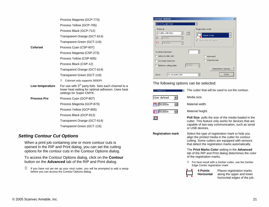
Setting Contour Cut Options When a print job containing one or more contour cuts is opened in the RIP and Print dialog, you can set the cutting options for the contour cuts in the Contour Options dialog. To access the Contour Options dialog, click on the Contour button on the Advanced tab of the RIP and Print dialog.
If you have not yet set up your vinyl cutter, you will be prompted to add a setup before you can access the Contour Options dialog.
The following options can be selected:
The cutter that will be used to cut the contour.
Media size.
Material width.
Material height.
Poll Size: polls the size of the media loaded in the cutter. This feature only works for devices that are capable of two-way communication, such as serial or USB devices.
Select the type of registration mark to help you align the printed media in the cutter for contour cutting. Some cutters are equipped with sensors that detect the registration marks automatically.
The Print Marks Color setting in the Advanced tab of the RIP and Print dialog determines the color of the registration marks.
For best result with a Gerber cutter, use the Gerber Edge Center registration mark.
Registration mark
4 Points Horizontal
Places registration marks along the upper and lower horizontal edges of the job.

© 2005 Scanvec Amiable, Inc. 22
Vertical Places registration marks on
the right side of the image. The arrow in the registration mark indicates the media feed direction for cutting.
Horizontal Places registration marks on
the bottom of the image. The arrow in the registration mark indicates the media feed direction for cutting.
Gerber Edge
Special registration mark for Gerber Edge.
Gerber Edge Center
The Gerber Edge registration mark, located along the center of the lower horizontal edge.
Gerber Type 3
An outline is traced around the outside of the image.
OPOS Gerber Odyssey positioning marks.
One set for all copies
If checked, only one set of registration marks will be printed for the entire job.
Advance after plot Check to lift the knife and advance the media after output, then reset the origin.
Cut page crossings Cuts the borderline of a page when the output is tiled into several pages.
Optimize cutting order
When this option is not selected, the objects are cut or plot in the order they were created. When selected, the software processes the objects within the specified section of length before moving to the next section.
Auto-weld Removes intersections of overlapping objects of the same color.
Weed border Cuts a border around all objects in the selected color.
Send Specify how the job will be sent to the output device:
As hybrid job
Sends both printing and cutting data as a single job. This option is available for hybrid printer/cutter devices.
As separate jobs
Sends printing and cutting data as separate jobs. This option is available if you use different devices for cutting and printing. This is also known as virtual hybrid output.
Print job only
Sends only the printing job.
Contour job only
Sends only the cutting job
When finished, click Done to return to the Advanced tab of the RIP and Print dialog.
Setting Cutter Driver Options The Cutter Driver Options dialog allows you to set a number of options that affect the way the cutter will operate. To access the Cutter Driver Options dialog, select the cutter in the Contour Options dialog and click Cutter Driver Options.
Select the cutting/pen speed you want to use. The options in the lower part of the screen will automatically be adjusted to match the defaults for the setting you select. You can then check an option and edit its value. The available settings are:
None Select this setting if you want the output device to determine all options.

© 2005 Scanvec Amiable, Inc. 23
Cut Fast Cut Medium Cut Slow
Select if you want to cut at high, medium or low speed.
Pen Plot Fast Pen Plot Medium Pen Plot Slow
Select if you want to plot with a pen at high, medium or low speed.
Pounce Select if you want to create a perforated pattern with the pounce tool.
The options in the lower part of the screen are:
Tool Defines the tool when several tools are available or switch between cut and plot. Check to set the desired value.
Speed The traveling speed of the cutting head. Check to set the desired value.
acceleration The acceleration experienced by the cutting head. Check to set the desired value.
force The amount of pressure brought to bear on the blade. Check to set the desired value.
bladeOffset The amount that the blade is offset from the center point on the plotter. Check to set the desired value.
pulldown_length The length of media that the cutter will advance then rewind before cutting. This is done to ensure that the media will not run out of slack in the middle of the job, which could tear the media or distort the image. Check to set the desired value.
Click OK to close the Cutter Driver Options dialog and return to the Contour Options dialog.
Turning Off Supercell Halftoning Supercell halftoning is on by default. To turn it off: 1. Open the job in the RIP and Print dialog. 2. Select the Advanced tab.

© 2005 Scanvec Amiable, Inc. 24
3. Click Screen.
4. Clear the Supercell Halftoning box. 5. Click OK to close the dialog and return to the Advanced
tab of the RIP and Print dialog.

© 2005 Scanvec Amiable, Inc. 25
Outputting Jobs in Production Manager By default, jobs sent to Production Manager are automatically RIPed and output, then deleted. This is controlled by the sending mode selected in the RIP and Print dialog (see page 17). If the Hold in list sending mode is used, jobs will be held in the Production Manager queue until you send them to the output device manually.
Selecting Jobs To select a job, click on its listing. Multiple jobs can be selected using the standard Windows CTRL and SHIFT methods:
• Hold the CTRL key to select multiple individual jobs.
• Hold the SHIFT key to select a range of jobs by clicking on the first and last jobs in the range.
To select all the jobs, from the Edit menu select Select All.
Deleting Jobs To delete a job, do one of the following:
• Select the job and press the Delete or Backspace key on your keyboard.
• Select the job and from the Edit menu, select Delete.
• Select the job and click the Delete button in the toolbar.
• Right-click the job, then select Delete from the context menu.
Moving jobs to a Different Output Device To move a job to a different output device setup, do one of the following:
• Select the job and select Move from the File menu, then select the new setup and click OK.
• Click and drag the job onto the icon for the new output device’s setup in the Setup Pane.
Sending Jobs to Output Devices To print a job, do one of the following:
Sending the Contour Cut from a Virtual Hybrid Job When a job containing contour cuts is RIPed as a virtual hybrid job, both a print job and a separate cutting job are generated. The print job will be output automatically, but the contour cut job must be sent to the cutter manually. This is done to give the user the time to get the output out of the printer and load it into the cutter. To output the contour cut of a virtual hybrid job on a Gerber cutter: 1. Load the printed output into the cutter. 2. Send the job to the cutter using one of the following
methods:
• Select the job and from the File menu, select Send.
• Right-click the job and select Send from the context menu.
3. Use the front panel controls on the cutter to position the
head of the cutting device over the Gerber registration mark.
4. Press the RUN/START JOB button on the cutting device (or Run Single, etc.).
5. Click OK.
© 2005 Scanvec Amiable, Inc. 26
Appendix A: Troubleshooting Issues
Hardware Key Issues Flexi automatically installs drivers for both Rainbow and Aladdin keys, and both drivers are automatically configured to check both USB and LPT ports. If you only have a single key, or all keys you have connected are of a single brand, then the key drivers that are not used should be removed in order to avoid any possible conflicts. Even if the key is not attached to the LPT port, the key driver will still query the port occasionally. This can lead to data transmission problems. In addition, you should configure your driver to look for only USB if you use a USB key, or LPT if you use an LPT key.
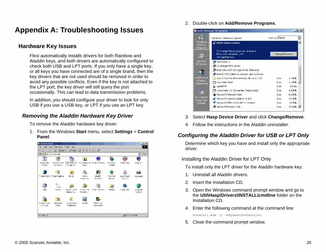
Removing the Aladdin Hardware Key Driver To remove the Aladdin hardware key driver: 1. From the Windows Start menu, select Settings > Control
Panel.
2. Double-click on Add/Remove Programs.
3. Select Hasp Device Driver and click Change/Remove. 4. Follow the instructions in the Aladdin uninstaller.
Configuring the Aladdin Driver for USB or LPT Only Determine which key you have and install only the appropriate driver.
Installing the Aladdin Driver for LPT Only To install only the LPT driver for the Aladdin hardware key: 1. Uninstall all Aladdin drivers. 2. Insert the Installation CD. 3. Open the Windows command prompt window and go to
the Util\Hasp\Drivers\INSTALL\cmdline folder on the Installation CD.
4. Enter the following command at the command line: hinstall.exe -i -keysearch=Parallel
5. Close the command prompt window.

© 2005 Scanvec Amiable, Inc. 27
Installing the Aladdin Driver for USB Only To install only the USB driver for the Aladdin hardware key: 1. Uninstall all Aladdin drivers. 2. Insert the Installation CD. 3. Open the Windows command prompt window and go to
the Util\Hasp\Drivers\INSTALL\cmdline folder on the Installation CD.
4. Enter the following command at the command line: hinstall.exe -i -keysearch=USB
5. Close the command prompt window.
Removing the Rainbow Hardware Key Driver(s) To remove the Rainbow hardware key drivers: 1. Run the Rainbow installer (setupx86.exe) found in the
Util\rainbow\WIN_NT folder of the Installation CD.
2. From the Functions menu, select Remove Sentinel Driver.
3. Click OK.
4. Click OK. 5. From the Functions menu, select Quit.
Configuring the Rainbow Drivers for LPT Only To install only the LPT driver for the Rainbow hardware key: 1. Uninstall all Rainbow drivers. 2. Insert the Installation CD. 3. Open the Windows command prompt window and go to
the Util\Rainbow folder on the Installation CD. 4. Enter the following command at the command line:
setup /v"/qb ADDLOCAL=Parallel_Driver"
5. Close the command prompt window.
Reinstallation Issues When you reinstall the application, all of the hardware drivers will be reinstalled, including any drivers that you may have removed. Also, any hardware key settings that you change will be overwritten to their default values.

© 2005 Scanvec Amiable, Inc. 28
Using Flexi and Gerber Omega on the Same System (Warp 9 Driver Issue)
Installing both Flexi and Gerber Omega on the same system can cause problems with the Warp 9 parallel port driver. The Warp 9 driver is a high-speed parallel port driver that offers increased performance over the standard Microsoft Windows driver. Both Flexi and Gerber Omega use this driver to provide better performance when outputting a job. However, it appears that Gerber Omega uses a different version of the driver than Flexi does. This can lead to problems outputting jobs through the parallel port. To resolve problems with the Warp 9 driver when both programs are installed on the same computer: 1. Check if the Warp 9 driver is running:
a. From the Windows Start menu, select Programs > Accessories > System Tools > System Information.
b. In the Tree window, under Software Environment,
select Drivers.
c. If the Warp 9 driver is running, it will be listed under the
name par1284, and its state will be listed as Running. 2. If the Warp 9 driver is not running, uninstall then reinstall
the Warp 9 driver: a. From the Windows desktop, right-click on My
Computer, and select Properties.

© 2005 Scanvec Amiable, Inc. 29
b. Select the Hardware tab.
c. Click on Device Manager.
d. From the View menu, select Show hidden devices.
e. If Par1284 is listed under Non-Plug and Play Drivers,
then uninstall it: i. Right-click on Par1284 and select Uninstall.
ii. Click OK.
iii. Click Yes to restart your computer.

© 2005 Scanvec Amiable, Inc. 30
f. Reinstall the Warp 9 driver: i. Run the 1284Inst.exe program located in the
Program sub-folder of the folder that Flexi was installed into.
ii. Restart your computer.

© 2005 Scanvec Amiable, Inc. 31
Configuring Serial Ports for Gerber Cutters To configure a serial port to work with a Gerber cutter: 1. From the Windows Control Panel, double-click on System.
2. Select the Hardware tab.
3. Click on Device Manager.

© 2005 Scanvec Amiable, Inc. 32
4. Click on Ports (COM & LPT).
5. Double-click on Communications Port (Com1).
If more than one COM port is present, click on the one the cutter is connected to.
6. Select the Port Settings tab.
The port settings selected are unimportant, since Flexi will override them.
7. Click on Advanced.
8. Clear the Use FIFO buffers check box.
Using FIFO buffers speeds communication, but can cause reliability issues. When outputting to a cutter, speed is not critical, since the data is highly compressed. In this case, it is better to disable the FIFO buffers.
9. Click OK to return to the Communications Port Properties dialog.
10. Click OK to save the changes to the serial port.