Embed Size (px)
Citation preview

FlexFrame™ for SAP®
Version 5.0A
Management Tool
Edition March 2011 Document Version 1.3

Fujitsu Limited
© Copyright Fujitsu Technology Solutions 2010
FlexFrame™ and PRIMERGY™ are trademarks of FujitsuSAP® and NetWeaver™ are
trademarks or registered trademarks of SAP AG in Germany and in several other countries
Linux® is a registered trademark of Linus Torvalds
SUSE® Linux is a registered trademark of Novell, Inc., in the United States and other
countries
Java™ is a trademark of Sun Microsystems, Inc. in the United States and other countries
Intel® and PXE® are registered trademarks of Intel Corporation in the United States and
other countries
MaxDB® is a registered trademark of MySQL AB, Sweden
MySQL® is a registered trademark of MySQL AB, Sweden
NetApp®, Network Appliance®, Open Network Technology for Appliance Products™, Write
Anywhere File Layout™ and WAFL™ are trademarks or registered trademarks of Network
Appilance, Inc. in the United States and other countries
Oracle® is a registered trademark of ORACLE Corporation
EMC®, CLARiiON®, Symmetrix®, PowerPath®, Celerra™ and SnapSure™ are trademarks
or registered trademarks of EMC Corporation in the United States and other countries
Vmware, the Vmware "boxes logo and design, Virtual SMP and Vmotion are regis-tered
trademarks or trademarks (the Marks) of Vmware, Inc. in the United States and/or other
jurisdictions.
Ethernet® is a registered trademark of XEROX, Inc., Digital Equipment Corporation and Intel
Corporation
Windows® and Word® are registered trademarks of Microsoft Corporation
All other hardware and software names used are trademarks of their respective companies.
All rights, including rights of translation, reproduction by printing, copying or similar methods,
in part or in whole, are reserved.
Offenders will be liable for damages.
All rights, including rights created by patent grant or registration of a utility model or design,
are reserved.
Delivery subject to availability. Right of technical modification reserved.


Management Tool
Contents
1 Introduction ..................................................................................................... 1 1.1 Notational Conventions ..................................................................................... 2 1.2 Document History .............................................................................................. 2 1.3 Related Documents ........................................................................................... 3
2 Network Concept ............................................................................................. 5 2.1 Brief abstract of the Network Concept. .............................................................. 5 2.2 FlexFrame network external connections .......................................................... 5 2.2.1 External Connectivity ......................................................................................... 5 2.2.2 Global Connectivity - Client LAN connection ..................................................... 6 2.2.3 Core Switch connectivity for devices ................................................................. 6 2.2.4 Uplinks for switchgroups ................................................................................... 6 2.3 Define SNMP Communities ............................................................................... 8 2.4 Host Names....................................................................................................... 9
3 Working with the Management Tool ............................................................ 11 3.1 Starting the Management Tool ........................................................................ 11 3.2 Exit the Management Tool .............................................................................. 11 3.3 Screen Layout of the Management Tool ......................................................... 12 3.4 Error Logging ................................................................................................... 14
4 Brief Instruction for Creating a New FlexFrame Configuration ................. 15
5 Object Tree..................................................................................................... 17 5.1 General Features ............................................................................................ 17 5.2 "FlexFrame" Object ......................................................................................... 18 5.3 "Control Center" Object ................................................................................... 19 5.4 "Network" Object ............................................................................................. 21 5.5 "Storage" Object .............................................................................................. 23 5.6 "Pools" Object ................................................................................................. 24 5.8 "ESX Servers" Object ...................................................................................... 28 5.9 "Chassis" Object .............................................................................................. 30 5.10 "Global Connectivity" Object ............................................................................ 31
6 View Area ....................................................................................................... 33 6.1 General Features ............................................................................................ 33 6.2 "General Information" ...................................................................................... 34 6.3 "Pools" ............................................................................................................. 35 6.4 "Controlling" ..................................................................................................... 36 6.5 "Application Nodes" ......................................................................................... 38 6.6 "NAS Storage" ................................................................................................. 40 6.7 "Volumes" and "Pool / SID Mount" .................................................................. 41

Contents
Management Tool
6.7.1 "Volumes" ........................................................................................................ 42 6.7.2 "Pool / SID Mount" ........................................................................................... 42 6.8 "SAP Services" ................................................................................................ 43 6.9 "Users Groups Services" ................................................................................. 46 6.10 "External Connectivity" .................................................................................... 46 6.11 Chassis ............................................................................................................ 49 6.12 Switch Blades .................................................................................................. 50 6.13 "ESX Servers" ................................................................................................. 50 6.14 "Wiring" ............................................................................................................ 52
7 Menu Functions ............................................................................................. 53 7.1 Creating a New Configuration .......................................................................... 53 7.1.1 "New Configuration" Function .......................................................................... 53 7.1.2 "Open LDAP Connection" Function ................................................................. 56 7.1.3 "Open Configuration File" Function ................................................................. 58 7.2 Modifying an Existing Configuration ................................................................ 58 7.3 Saving a Configuration .................................................................................... 59 7.4 Saving for Installation ...................................................................................... 60 7.5 Printing a Configuration ................................................................................... 61 7.6 Editing a Configuration .................................................................................... 61 7.7 Validating a Configuration................................................................................ 62 7.8 Generating a Network Wiring Plan .................................................................. 62 7.8.1 Automatic Generation ...................................................................................... 63 7.8.2 Manual Generation .......................................................................................... 63 7.9 Generating Global Connectivity ....................................................................... 64 7.9.1 Automatic Generation ...................................................................................... 64 7.9.2 Manual Generation .......................................................................................... 65 7.10 Generating Host Parts of IP Addresses ........................................................... 66 7.10.1 Generate Host Parts Automatically .................................................................. 67 7.10.2 Generate Host Parts Manually ......................................................................... 67
8 Actions ........................................................................................................... 69 8.1 Overview.......................................................................................................... 69 8.2 Context Menu of selected Objects ................................................................... 71 8.3 Adding Application Nodes................................................................................ 73 8.4 Adding Blade Server Chassis .......................................................................... 76 8.5 Adding Control Stations ................................................................................... 77 8.6 Adding Data Movers ........................................................................................ 77 8.7 Adding Data NICs ............................................................................................ 78 8.8 Adding External Connectivities (Pool-specific) ................................................ 79 8.9 Adding LAN Interfaces ..................................................................................... 80 8.10 Adding Mount Points for Volumes ................................................................... 80 8.11 Adding NAS Systems ...................................................................................... 81 8.11.1 Celerra SRDF-NAS Active/Passive Configuration ........................................... 82 8.12 Adding Pool Groups ........................................................................................ 82
Contents
Management Tool 3
8.13 Adding Pools ................................................................................................... 83 8.14 Adding SAP Services ...................................................................................... 84 8.15 Adding Switches .............................................................................................. 92 8.16 Adding Switch Groups ..................................................................................... 93 8.17 Adding Switch Ports ........................................................................................ 93 8.18 Adding Volumes .............................................................................................. 93
9 Abbreviations ................................................................................................ 95
10 Glossary ......................................................................................................... 99
11 Index ............................................................................................................. 105


Management Tool 1
1 Introduction
The FlexFrame™ for SAP Management Tool is the successor of the FlexFrame for SAP
Planning Tool. It takes over all the functions of the former Planning Tool and moreover
offers a variety of new functions as well as the potential to further basic extensions of the
functionality in the future. Although its implementation compared with the predecessor is
based on fundamentally different technologies (Java and XML versus Microsoft Excel).
One aim was to give a familiar and as far as possible compatible look and feel for its
users.
The FlexFrame for SAP Management Tool works together with FlexFrame for SAP
versions 4.2A, whereas the previous FlexFrame for SAP Planning Tool works together
with all FlexFrame for SAP versions prior to 4.2A.
This manual describes how to work with the FlexFrame Management Tool which enables
the certified FlexFrame consultant to enter the necessary configuration data for a
customer-specific FlexFrame environment on a Windows® PC with Java SE 6 and newly
also on other platforms, e.g. Linux.
With this tool you can
create an initial FlexFrame configuration file.
modify an existing FlexFrame configuration file (new!).
open an LDAP connection to a server to get a current FlexFrame configuration to be
used as initial configuration (new!) .
create/modify the network cabling plan.
After the data has been entered correctly, it is stored in an XML file on an approved
external data medium (e.g. an USB stick) and later read in by the installation scripts
during the installation of the FlexFrame Control Center. The required FlexFrame
configuration is implemented automatically using this configuration data.
The two Control Nodes (CN) of FlexFrame for SAP are also named as the
FlexFrame Control Center (CC).
In this documentation the notation Control Node (CN) is used as a synonym for
Control Center (CC) and the other way round.

Introduction Notational Conventions
2 Management Tool
Among other things, the configuration files contain information on the:
Network switch configuration DHCP parameters
Hosts User and group parameters
Services FlexFrame pool and group definitions
NAS storage configuration SAP services
Network boot parameters Database systems
LDAP parameters Network wiring plan
This document is only to be used by Certified FlexFrame Consultants who have
completed FlexFrame and Network Appliance® Filer training or EMC NAS Storage
training. They also should have expert knowledge of Linux® OS.
SAP system installations should only be performed by consultants who are certified for
your operating system, your database, and the SAP system you are installing.
1.1 Notational Conventions
The following conventions are used in this manual:
Additional information that should be observed.
Warning that must be observed.
fixed font Names of paths, files, commands, and system output.
<fixed font> Names of variables.
fixed font User inputs in command examples
(if applicable using <> with variables).
1.2 Document History
Document Version Changes Date
1.0 First Edition 2010-08-31
1.1 Update 2010-12-09
1.2 Update 2010-12-31
1.3 Update 2011-03-23

Related Documents Introduction
Management Tool 3
1.3 Related Documents
FlexFrame™ for SAP® – Administration and Operation
FlexFrame™ for SAP® – HW Characteristics Quickguides
FlexFrame™ for SAP® – Installation ACC 7.2
FlexFrame™ for SAP® – Installation Guide for SAP Solutions
FlexFrame™ for SAP® – Installation of a FlexFrame Environment
FlexFrame™ for SAP® – Management Tool
FlexFrame™ for SAP
® – myAMC.FA_Agents Installation and Administration
FlexFrame™ for SAP
® – myAMC.FA_Messenger Installation and Administration
FlexFrame™ for SAP
® – myAMC.FA_LogAgent Installation and Administration
FlexFrame™ for SAP® – Network Design and Configuration Guide
FlexFrame™ for SAP® – Security Guide
FlexFrame™ for SAP® – Technical White Paper
FlexFrame™ for SAP® – Upgrading FlexFrame 4.1A, 4.2A or 4.2B to 5.0A
ServerView Documentation
SUSE Linux Enterprise Server Documentation


Management Tool 5
2 Network Concept
The FlexFrame "Network Design and Configuration Guide" defines valid FlexFrame
Network configurations. In the “Management Tool Guide” you will just find a description
how to enter a valid configuration into the Management Tool.
If you are already familiar with the network concept of FlexFrame, please continue with
chapter "Working with the Management Tool" on page 11.
2.1 Brief abstract of the Network Concept.
The network is the backbone of the FlexFrame solution. Communication between the
various nodes is done exclusively over the IP network infrastructure. This is used both for
communication between server(s) and client(s) and for delivering data from the NAS
(Network Attached Storage) to the server.
The IP network infrastructure is essential for every FlexFrame configuration. FlexFrame is
designed with a dedicated network for connections between server and storage that is
reserved for FlexFrame traffic only.
The FlexFrame internal physical network configuration is fully redundant to ensure high
availability. Based on this physical network, a number of virtual network segments are
configured. One virtual LAN (VLAN) is used for FlexFrame infrastructure management
and is called the Control LAN. Three further VLANs, the Client LAN, the Server LAN and
the Storage LAN, are added for each pool. A pool is a set of Application Nodes in a
FlexFrame environment plus a set of preconfigured SAP services that belong to the same
customer. A pool is usually related to a client. By assigning separate VLANs to every pool
these clients are well separated. This multi client capability of FlexFrame is an essential
feature.
2.2 FlexFrame network external connections
For network connections of the internal FlexFrame networks to the customer corporate
LAN the following features are provided.
2.2.1 External Connectivity
With External Connectivity you are able to define abstract devices with one or two NICs
and with one to four LAN Adresses for the Pool specific LANs and the Ctrl LAN. External
Connectivity exists in a pool scope.
A more detailed description of this feature you will find under 6.10 "External Connectivity"

Network Concept FlexFrame network external connections
6 Management Tool
2.2.2 Global Connectivity - Client LAN connection
With Global Connectivity you are able to define device independent global connectivity.
Using this feature you can define switch ports that provide access to certain (Client)
LANs. Since you are able to provide access to several Client LANs of different pools on
one redundant pair of switch ports, global connectivity is defined in a global scope, not in
a pool specific scope.
A more detailed description of this feature you will find under 7.9 Generating Global
Connectivity.
2.2.3 Core Switch connectivity for devices
You can connect NAS devices and servers to a connectivity cloud that is named "Core or
Direct".
Connecting FlexFrame devices to the "Core or Direct" cloud just means, that FlexFrame
is not configuring any switches for these devices.
“Core or Direct” in the Management Tool is just like an abstract switch positioned directly
under the Network Object (see 5.4 "Network" Object). If not yet existing, you can “right-
click” on the Network Object and add a “Core or Direct” object. As children of the “Core or
Direct” object you can right-click on the “Core or Direct” object and add portlist objects. As
children of these portlist objects you can add different kind of switch ports, as many as
you need. Via the link property of the switchport object or the link property of a data NIC
object you are able to relate the NIC of a device with the SWP of the “Core or Direct”
cloud.
All devices in a FlexFrame installation may be connected to any portlist of “Core or Direct”
2.2.4 Uplinks for switchgroups
Automatic creation of uplinks is done by calling the wiring menu function (see 7.8
Generating a Network Wiring Plan) after having set the networking properties (see page
22).
Uplinks for 3750 SWGs will be created as described in the networking properties. Nexus
5000 SWGs will use uppermost switch ports just below the switch ports that are used as
VPC peer links.
The wiring menu function creates uplinks. The wiring function does not
necessarily create plug compatible uplinks that you can use for any
possible direct connection of switch groups.
Manually you can create uplinks in the Management Tool by linking switch ports of a
switch group to switch ports of “Core or Direct”. To be able to set the “link” property of a

FlexFrame network external connections Network Concept
Management Tool 7
SWP to point to another SWP the “switch interconnect” property of the SWP has to be set
to “true”. To configure uplinks to “Core or Direct” you should use different switches of a
switch group to have a failsafe uplink connection of your switch group. All connections of
a SWG to the same portlist of “Core or Direct” form one link aggregate.
If you want to configure more than one uplink for a switch group you have
to use for each uplink channel a different portlist of “Core or Direct”
“Core or Direct” is just an abstract, not really existing switching device that represents
network connectivity not in the responsibility of FlexFrame. When you are using uplinks of
two switch groups to the same portlist of “Core or Direct” to connect these two switch
groups directly with each other, then you have to take care, that the uplinks of one switch
group use the same kind of switch ports as the uplinks of the other switch group.
To put the attention of the certified FlexFrame consultant, who is planning network
connectivity, to this fact, a warning will be displayed when validating and switch ports of
different type are found in the same portlist.
If the pointed out uplinks will not be used for a direct connection, you can ignore this
warning.
The uplinks, that you want to use for a direct connection of two switch
groups have to be plug compatible
Network Concept Define SNMP Communities
8 Management Tool
2.3 Define SNMP Communities In order to be able to send SNMP traps to the control center, the switches of a switch
group and the switch blades of the blade chassis need a specified SNMP community.
This community is defined via the Management Tool. As default value "public" (read only)
is set. The community is set at the following locations in the object tree:
for the control center in the "control center" object, see section 5.3 "Control Center"
Object on page 19)
for the switches of a switch group in every switch group object
for every switch blade object of a blade chassis
In FlexFrame select the same community for all three kinds of devices.

Host Names Network Concept
Management Tool 9
2.4 Host Names
The host names of the individual VLANs are derived from the general host names of the
respective components (e.g. Application Nodes). With exception of the Client LAN the
host names are provided with a suffix to permit an individual addressing via a VLAN
segment:
Control LAN:
Server LAN:
Storage LAN:
<general_host_name>-co
<general_host_name>-se
<general_host_name>-st
In SAP environments host names are currently limited to 13 alpha numeric
characters including the hyphen ("-"). The first character must be a letter. In the
SAP environment host names are case-sensitive (see SAP Note No. 611361).


Management Tool 11
3 Working with the Management Tool
3.1 Starting the Management Tool
The Management Tool is shipped on the Service CD in the directory /config.
It consists of the Jar files MgmtTool.jar, xercesImpl.jar and xml-apis.jar and
and the configuration file ff_hardware.xml which have to be copied into the same
directory under Windows or Linux.
● You can start the Management Tool in the Windows Explorer doing a double click on
MgmtTool.jar.
● You also can start the Management Tool on the command line interface in the
following way:
● Navigate to the directory which contains the MgmtTool.jar.
● Type java –jar MgmtTool.jar
SUN Java SE 6 is required.
The screen of the Management Tool opens. For an explanation of the different areas see
the following section Screen Layout of the Management Tool.
At the moment the Management Tool does not possess a recovery
function (Redo/Undo)!
If you delete something by mistake, you can repair it by
adding it again or
saving frequently to a configuration file and reading in the configuration file
again with the Open -> Configuration File function.
In the latter case, all input that you made previously is lost.
3.2 Exit the Management Tool
You exit the Management Tool by selecting Exit in the File menu.

Working with the Management Tool Screen Layout of the Management Tool
12 Management Tool
3.3 Screen Layout of the Management Tool
The screen of the Management Tool consists of three different areas, in which you can
execute the configuration tasks.
The following figure is a photomontage illustrating all areas. Depending on the
individual procedure step, all areas are not always visible.
1. Menu bar
Here you find administrative functions of the Management Tool.
2. Object tree
Here you find an abstract object tree that represents a FlexFrame installation.
When you select an object tree element in this area with a left mouse click you get a
differentiated view on this in the view area (3).
This means, the selected object in the object tree determines the content of the view
area. In other words, every object has an object view that is displayed in the view
area.

Screen Layout of the Management Tool Working with the Management Tool
Management Tool 13
Generally every object displays in its object view the information that is displayed
within the leaf objects of its sub-tree. If you select a leaf object only the properties of
the selected object are displayed in the view area.
Depending on the selected object you can open a context menu with a right mouse
click on the object. Via context menus you can perform object dependent actions.
Generally the actions are "delete" and "add".
3. View area
Depending on the selected object in the object tree, an object view is opened in this
area. Generally an object view displays information of the sub-tree of the selected
object.
Objects and object views are loosely coupled. You can group the available views as
follows:
● Property view, which displays only the properties of a selected object. This view
is a standard View of a leaf object.
● Table views, which collect – as in the old Excel Planning Tool – information of
Application nodes, NAS Systems, SIDs, etc.
● Combinations in form of a split pane or in form of a tabbed pane of table views
and property views.
In all views you will find editable fields or dropdown combo boxes, where you can
change the values of the related properties.
If applicable, there are buttons above a table for performing actions. Each action
produces a new object-dependent sub-tree in the object tree.
When you select the FlexFrame object, the root object of the FlexFrame object tree,
you get information on the whole FlexFrame installation in the FlexFrame object
view. To group this information, the FlexFrame object view contains an additional tab
bar.
Depending on the selected tab in this bar, you get a global view on the configuration,
grouped by the kind of FlexFrame object, e.g. Application Nodes, Volumes or NAS
devices.
For defining a basic Flexframe configuration most of the settings are set in these
tabs.
For users of the old Excel Management Tool the FlexFrame object view (short:
FlexFrame view) with its tabbed panes will look familiar.
For defining details of a configuration, which are not visible or changeable in
the global views, you have to select the corresponding object in the object
tree – mostly leaf objects - and set the properties right at the objects itself.

Working with the Management Tool Error Logging
14 Management Tool
3.4 Error Logging
In case of unexpected behavior of the Management Tool you have to view the contents of
the file ManagementToolLog.txt located in the directory from where you started the
Management Tool.
In this file you find information of the available ff_hardware.xml files parsed and in
case of an error more detailed information on the error.
In case your ff_config.xml or the LDAP content of a FlexFrame installation that you
evaluated contains hardware, which is not available in your ff_hardware.xml you will
find this information only here in ManagementToolLog.txt.
If a "java call stack" is logged, this means that a not yet handled error situation occurred.
In such a case it is strongly recommended to save you configuration and terminate the
Management Tool.
For all Management Tool sessions the information is accumulated in this log file.

Management Tool 15
4 Brief Instruction for Creating a New FlexFrame Configuration
The validation of a complete FlexFrame configuration is done by using the Validate Configuration function (see section Validating a Configuration
on page 62).
First add all your devices to the configuration then configure all IP addresses
and then do the wiring of the whole configuration. Name conflicts and conflicting
IP addresses are much better resolved when having the global view on all
devices of a FlexFrame configuration.
Before writing a FlexFrame configuration into a configuration file the validation is
always performed automatically and the resulting number of errors will be written
into the configuration file. If there are validation errors you will not be able to use
the configuration file for installing a FlexFrame system.
Therefore it is necessary to use the Validate Configuration function at
the end of a FlexFrame configuration setup. It is also recommended to validate a
configuration several times before.
To create a new FlexFrame configuration, perform the following steps:
1. After starting the Management Tool (see section 3.1), select New Configuration
in the File menu (see section 7.1.1).
A dialog box opens in which you have to specify the parameters for the first pool of
the new FlexFrame environment. The input fields of this dialog box contain default
values, which you can adapt according to your needs. Having done this, the new
configuration consists of one switch group, one pool with one group and one NAS
storage.
2. Add switches to the switch group (see section 8.15).
3. Add one or more blade server chassis (see section 8.4).
4. Add one or more ESX servers (see section xxx)
5. Add one or more application nodes (rack servers, blade servers, VMs, see section
8.3)
6. Add SAP services (see section 8.14) and corresponding SAP.
7. Generate the IP addresses (see section 7.10).
8. Generate the network wiring plan (see section 7.8).
9. Validate the configuration (see section 7.7). In case of errors you have to correct
them and validate the configuration again.

Brief Instruction for Creating a New FlexFrame Configuration
16 Management Tool
10. Save the valid configuration (see section 7.3).
If you want to use the configuration for later installation, the file name must
be ff_config.xml.
11. You can print the settings of the configuration (see section 7.4).
12. Optional activities:
● Add other switch groups to the desired configuration (see section 8.16).
● Add other pools to the desired configuration (see section 8.13).
● Add other groups to the existing pool(s) (see section 8.12).
● Add pool-specific external connectivities (see section 8.8).
● Add other NAS storages (see section 8.11).
● Add volumes to the NAS storage(s) (see section 8.18) .
● Add mount points for the added volumes (see section 8.10).
● Add global connectivities either manually or automatically with optional
additional Client LANs (see section 7.9).
.
Management Tool 17
5 Object Tree
The object tree is an abstraction of the FlexFrame reality.
5.1 General Features
Depending on the selected object in the object tree you get a differentiated view on this
object or on the sub-tree of this object in the view area. This means, the selected object
determines the content of the view area and the more deeply you are in the structure the
more differentiated is the display of the parameters.
Every object in the object tree has its object view in the view area.
When you select a leaf Object in the object tree, the object view is an editable view auf all
properties of this object. Then you can modify certain settings of this object. When you
select another object in the object tree you get - depending on the object - an editable
view of properties of all objects in the sub-tree.
Depending on the object in the object tree you can open a context menu by doing a right
mouse click on the object. Via context menus you can perform object dependent actions.
Each action modifies / produces an object-dependent sub-tree in this area.
On page 69 you find an overview of all actions.
With the Delete action you can delete all objects in the object tree.
This action is carried out directly, no safety inquiry will take place!
If you delete an object by mistake, you can repair it:
add it again in the object immediately above or
read it in the configuration file again with the
Open -> Configuration File function.
In the latter case, all input that you made previously is lost (if you did not
accomplish a backup in the meantime).
The object tree consists of the major object FlexFrame and seven basic objects
described in the following sections 5.2 to 5.10.
Object Tree "FlexFrame" Object
18 Management Tool
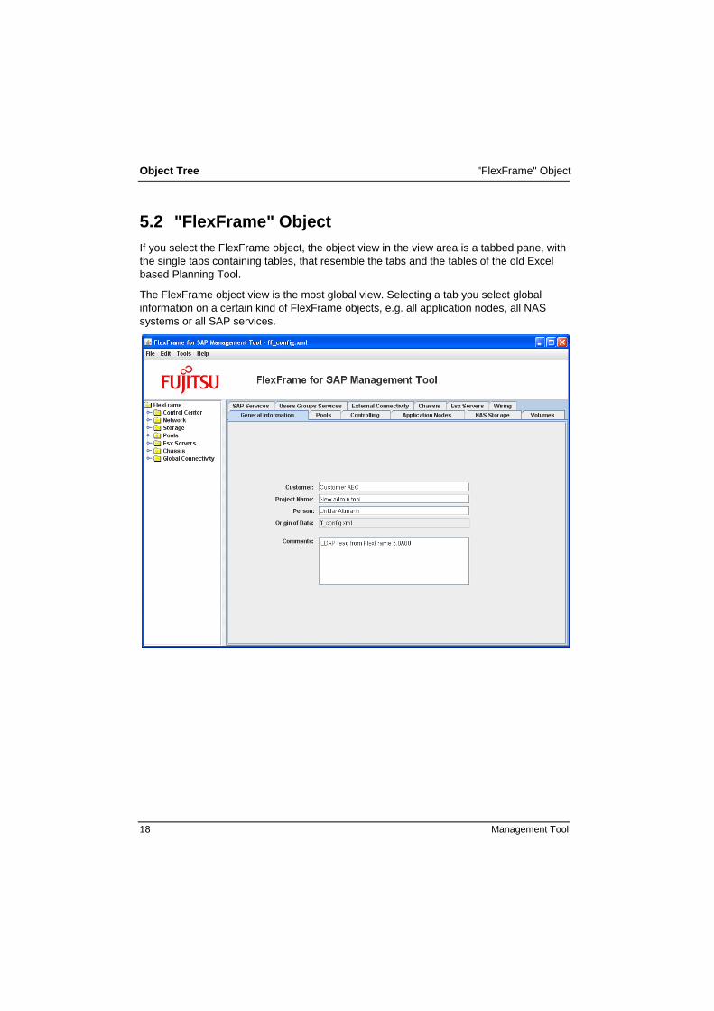
5.2 "FlexFrame" Object
If you select the FlexFrame object, the object view in the view area is a tabbed pane, with
the single tabs containing tables, that resemble the tabs and the tables of the old Excel
based Planning Tool.
The FlexFrame object view is the most global view. Selecting a tab you select global
information on a certain kind of FlexFrame objects, e.g. all application nodes, all NAS
systems or all SAP services.

"Control Center" Object Object Tree
Management Tool 19
5.3 "Control Center" Object
The Control Center consists of two clustered servers (Control Nodes) whose task is to
monitor and manage FlexFrame (e.g.: Storage, ANs, SIDs), i.e. to supply them with
information on the boot procedure, directory services (LDAP for hosts, services, etc.) and
more (FA Control Agents).
The figure on the left side shows the Control Center
object as an example.
By selecting this object, the Control Node part of the Controlling table is displayed (see page 36).
The upper split pane shows a list of properties necessary for
the Control Center (see Miscellaneous Control Center
settings below).
The lower split pane shows a table where more properties of
the Control Center are shown in a similar way as properties
of NAS systems or Application Nodes.
If a NIC is already connected to a switch port, the icon of the
NIC is marked green. The relation then also appears in the
wiring view.
Miscellaneous Control Center Settings Control Node DNS Domain DNS domain name of the Control Nodes. The name
has to exist already in the customer’s network
(e.g. myFlexFrame.ts.fujitsu.com).
The DNS domain name is required and has to
conform to RFC1035. This means, the domain parts
have to be separated by a dot and have to consist of
alphanumerical characters and dashes. Domain
parts may not begin with a number or a dash.
DNS Servers IPv4 addresses for DNS Domain Server (separated
by blanks). No entry is required for this field. If this
field is empty, fully qualified domain names outside
of FlexFrame cannot be resolved by neither the
Control Nodes nor the Application Nodes.
Object Tree "Control Center" Object
20 Management Tool
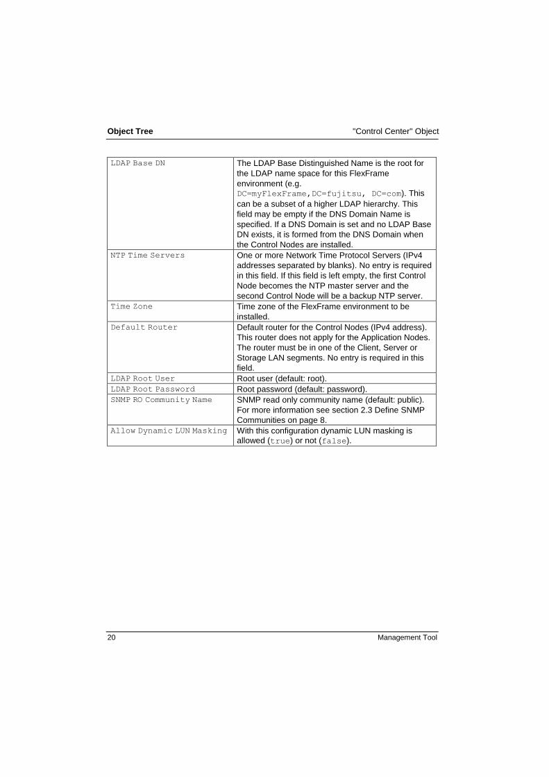
LDAP Base DN The LDAP Base Distinguished Name is the root for
the LDAP name space for this FlexFrame
environment (e.g. DC=myFlexFrame,DC=fujitsu, DC=com). This
can be a subset of a higher LDAP hierarchy. This
field may be empty if the DNS Domain Name is
specified. If a DNS Domain is set and no LDAP Base
DN exists, it is formed from the DNS Domain when
the Control Nodes are installed.
NTP Time Servers One or more Network Time Protocol Servers (IPv4
addresses separated by blanks). No entry is required
in this field. If this field is left empty, the first Control
Node becomes the NTP master server and the
second Control Node will be a backup NTP server.
Time Zone Time zone of the FlexFrame environment to be
installed.
Default Router Default router for the Control Nodes (IPv4 address).
This router does not apply for the Application Nodes.
The router must be in one of the Client, Server or
Storage LAN segments. No entry is required in this
field.
LDAP Root User Root user (default: root).
LDAP Root Password Root password (default: password).
SNMP RO Community Name SNMP read only community name (default: public).
For more information see section 2.3 Define SNMP
Communities on page 8.
Allow Dynamic LUN Masking With this configuration dynamic LUN masking is
allowed (true) or not (false).

"Network" Object Object Tree
Management Tool 21
5.4 "Network" Object
In this object the network infrastructure of the entire FlexFrame environment which is
used to implement redundant connection of all the FlexFrame components using
integrated switches is managed.
The figure on the left side shows the Network object
as an example.
If a switch port is already connected to a NIC, the icon
of the switch port is marked green. The relation then
also appears in the wiring view.
By selecting this object, the switch group part of the Controlling view is displayed in the lower split
pane (see page 36).
The upper split pane shows miscellaneous settings
concerning the network (see Miscellaneous Network
settings below).
Right-click on Switches to add switches, see section
8.15, Adding Switches on page 92.

Object Tree "Network" Object
22 Management Tool
Miscellaneous Network Settings
Client LANs on SWG ports true
Client LAN switch ports are configured on the
FlexFrame switches.
false
Client LAN switch ports are configured on core
switches.
One Client LAN per SWP1 true
For each Client LAN there is a pair of switch
ports with the untagged LAN.
false
For all Client LANs there is only one pair of
switch ports with the tagged LANs.
Client LANs on several SWGs2 true
The pair of Client LAN switch ports is
configured on the first two switch groups, one
port on the first switch group and the other port
on the second switch group.
false
The pair of Client LAN switch ports is
configured on the first switch group only.
Use 1GBit SWPs as uplinks true
1Gbit switch ports (the standard twisted pair
1GBit ports) are used for uplinks
false
Either SFP switch ports or 10GBit switch ports
are used for uplinks.
Use 1GBit SWPs for Client LANs3 true
1Gbit switch ports (the standard twisted pair
1GBit ports) are used for configured Client
Lans
false
Either SFP switch ports or 10GBit switch ports
are used for Client Lans.
Number of ports for uplinks Number of uplink ports (2 - 8).
1 corresponds to former „Separate VLANs to corporate LAN“
2 corresponds to former „Distribute corporate LAN ports to different switch groups”
3 corresponds to former “Use Fiber Optic port to corporate LAN“

"Storage" Object Object Tree
Management Tool 23
A switch group is typically used as a network unit for the redundant connection of the
hosts for each system cabinet (19" rack). This is intended to reduce the cabling outside
the system cabinet to a minimum.
The switches within a group are connected in such a way that the hosts are connected
with redundancy. The first two switches of a group are connected redundantly with the
neighboring switch groups across switch group boundaries. Connecting switch groups to
each other is in the responsibility of the customer. FlexFrame only provides uplink ports
at the switch groups.
5.5 "Storage" Object
In this object the central storage systems of the entire FlexFrame environment which can
be accessed by all Application Nodes are managed. Operating systems (shared OSs)
and application software are also stored centrally. Only the operating systems of the two
servers of the Control Center are stored on their local disks and not in the NAS storage.
The figure on the left side shows the Storage object as
an example.
If a NIC is already connected to a switch port, the icon of
the NIC is marked green. The relation then also appears
in the wiring view.
By selecting this object, the NAS Storage table is
displayed (see page 40).
The NAS Storage table view is also displayed as object
view for the Storage – NAS object.
Object Tree "Pools" Object
24 Management Tool
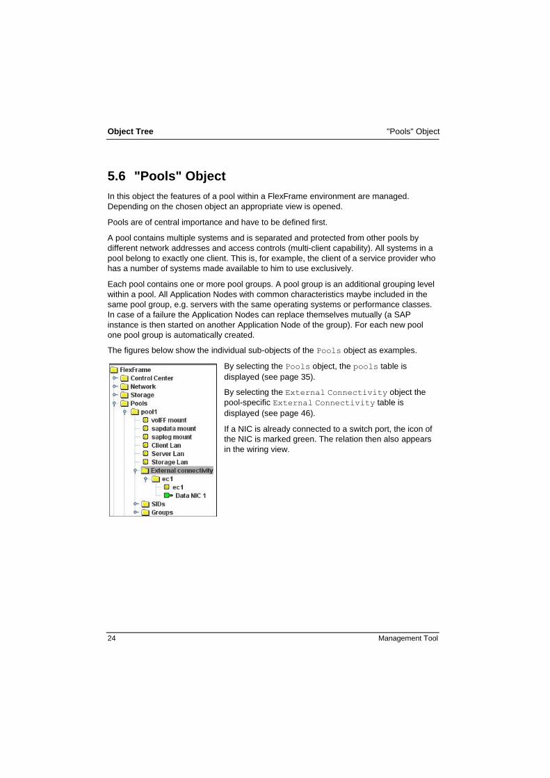
5.6 "Pools" Object
In this object the features of a pool within a FlexFrame environment are managed.
Depending on the chosen object an appropriate view is opened.
Pools are of central importance and have to be defined first.
A pool contains multiple systems and is separated and protected from other pools by
different network addresses and access controls (multi-client capability). All systems in a
pool belong to exactly one client. This is, for example, the client of a service provider who
has a number of systems made available to him to use exclusively.
Each pool contains one or more pool groups. A pool group is an additional grouping level
within a pool. All Application Nodes with common characteristics maybe included in the
same pool group, e.g. servers with the same operating systems or performance classes.
In case of a failure the Application Nodes can replace themselves mutually (a SAP
instance is then started on another Application Node of the group). For each new pool
one pool group is automatically created.
The figures below show the individual sub-objects of the Pools object as examples.
By selecting the Pools object, the pools table is
displayed (see page 35).
By selecting the External Connectivity object the
pool-specific External Connectivity table is
displayed (see page 46).
If a NIC is already connected to a switch port, the icon of
the NIC is marked green. The relation then also appears
in the wiring view.

"Pools" Object Object Tree
Management Tool 25
By selecting the SIDs object the SIDs object view is
displayed (see page 6.8 "SAP Services" on page 43).
In the upper split pane of the view you can manage the
pool-specific UIDs and GIDs that might be necessary
when installing and running the SAP services in the
given pool. During installation the UIDs or GIDs given
here are only used, when a SAP version or DB version
that makes use of this user or group is actually installed.
If there is no UID or GID given here for a user or a group
actually needed for a SAP or DB installation, then a
default value will be used. When migrating an existing
SAP Installation to FlexFrame, the existing UIDs and
GIDs should be used here.
In the lower part of the split pane the SAP Services
table is displayed. Only the SAP services belonging to
this pool are displayed.

Object Tree "Pools" Object
26 Management Tool
By selecting the Users Groups Services object
the three corresponding sub-objects are displayed.
Sub-object tree:
Click on the Users, Groups or Services
sub-object and all User names, Group names and
Services are displayed in the object tree.
Concurrently the corresponding view opens and Location, User Name and User ID are listed in
a table, e.g. see section 6.9, "Users Groups
Services" on page 46.
If you click on a specific user, group or service the
properties are displayed in the view area.
To delete a user, group or service click with the right-mouse tab and select Delete.
Object Tree
Management Tool 27
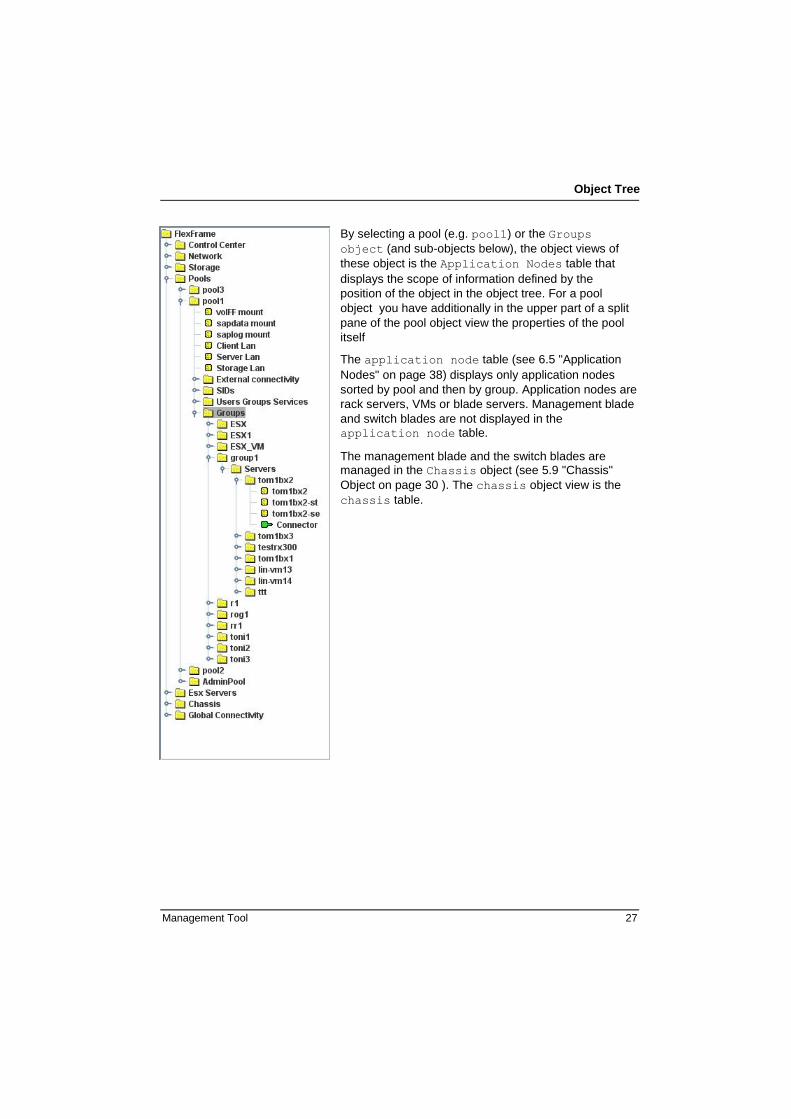
By selecting a pool (e.g. pool1) or the Groups
object (and sub-objects below), the object views of
these object is the Application Nodes table that
displays the scope of information defined by the
position of the object in the object tree. For a pool
object you have additionally in the upper part of a split
pane of the pool object view the properties of the pool
itself
The application node table (see 6.5 "Application
Nodes" on page 38) displays only application nodes
sorted by pool and then by group. Application nodes are
rack servers, VMs or blade servers. Management blade
and switch blades are not displayed in the
application node table.
The management blade and the switch blades are managed in the Chassis object (see 5.9 "Chassis"
Object on page 30 ). The chassis object view is the
chassis table.

Object Tree "ESX Servers" Object
28 Management Tool
5.8 "ESX Servers" Object
Instead of being used directly as Application Nodes, PRIMERGY servers may also be
used in FlexFrame as ESXi servers. An ESXi server can host a number of virtual ma-
chines that are used as Application Nodes.
VMware ESXi and VMware ESX are "bare-metal" hypervisors that form the foundation of
VMware vSphere. The VMware vSphere 4 product line supports three different types of
hypervisors - ESX classic, ESXi installable and ESXi embedded. In FlexFrame 5.0, only
ESXi installable and ESXi embedded are supported. However, the terms "ESX" and
"ESXi" are both used in the FlexFrame documentation and code to denote the VMware
hypervisor and always mean "ESXi" unless explicitly stated otherwise.
When starting a new FlexFrame configuration, the ESX Servers object is not yet present
in the object tree. It is created only after adding a first ESX server, for example by using
the Add ESX Server button of the ESX Server table that can be activated via the ESX
Servers tab of the FlexFrame root object view.
When selecting the Esx Servers object, ESX
related global FlexFrame parameters are
displayed in the view area (see table below) and
can be modified according to the configuration's
needs.
When selecting the VCenter subobject, data
related to the usage of a vCenter server in
Flexframe is displayed in the view area and can
be modified there.
You can add a new ESX Server via the Server
List object with a right mouse-click. A dialog
box opens and you can add an ESX server in
exact the same way as you add an Application
node to a Server List object inside a Group
object .
If the ESX server is a blade server you have to
relate blade with chassis via the Connector and
Slot object in the same way you relate a NIC to
a SWP of a Switch via Data NIC and switch port
object. When these objects are connected the
connecting objects will be marked green.
For further information on this topic, see section
5.9 "Chassis" Object on page 30.

"ESX Servers" Object Object Tree
Management Tool 29
ESX related global FlexFrame parameters
FlexFrame system code for
ESX and VM
A numeric value between 0 and 63 used to
generate MAC addresses for FlexFrame virtual
machines and to build names of some ESX
related resources such as port groups and
datastores.
Use a different system code for each
FlexFrame system in your environment.
vCenter Server usage
If FlexFrame ESX servers are administrated by a vCenter Server, the name and IP
address of the vCenter Server have to be known to FlexFrame.
To enter this information you have to use VCenter object.
The IP address can be an address in the FlexFrame Control LAN (select Control
Center / Control LAN in the link drop-down box) or an address outside
FlexFrame, which is reachable from the Control Nodes (select --- in the link drop-
down box).
If no vCenter Server is used, remove the VCenter object from the object tree: right-click
on the VCenter object and select Delete.

Object Tree "Chassis" Object
30 Management Tool
5.9 "Chassis" Object
In this object the management blade and the switch blades of all blade servers within a
FlexFrame environment are managed. The Chassis object view is the chassis table. The
Chassis table resembles the Application Node table and has some additional Chassis
related information for blade servers (e.g. slot number) and additionally the infrastructure
objects for chassis, like switch blades and management blades. Whereas the Application
Node table sorts objects by pool and by group in the Chassis table the objects are sorted
by chassis and by slot.
The figure on the left side shows the Chassis object as an
example.
With right-click action Add or Delete you can modify the
type of switch blades if you have to modify your initial
choice in the Add Chassis dialog.
The switch blade types include the type Pass-Thru,
which enables dedicated connections to specific server
blades and also enables to use part of the server blades
within FlexFrame and part of it outside of FlexFrame.
The server blades for a blade server must be specified
hereafter as Application Nodes or ESX Severs with a
Connector – Slot relation to the chassis.
For a server blade that occupies more than one slot, see
the "HW Characteristics Quickguides" to identify the main
slot object and which connector - slot object relations have
to be established to create a valid configuration.
When you add a server blade via the "Add AN" dialog you
will only have to relate the main connector object with a
slot object. The other connector - slot relations will be
established automatically.
If a NIC is connected to a switch port, the icon of the NIC is
marked green. The relation then also appears in the wiring
view.
If a server blade is connected to a slot, the icon of the slot
is marked green.

"Global Connectivity" Object Object Tree
Management Tool 31
5.10 "Global Connectivity" Object
In this object the global network connections are managed. For further information see
page 64.
The figure on the left side shows the Global Connectivity object as an example.
Under the ClLanCons object you can define global Client
LANs.


Management Tool 33
6 View Area
6.1 General Features
Depending on the selected object in the object tree, a view is opened in this area. This
view is generally called the object view. Every object has its own object view. For a Pool
object this view is called the pool object view for the pool list object, Pools, this is called
the Pools view.
For the convenience of the user the different kinds of views are very restricted in the
Management Tool.
Most common are tables, like Chassis table, Application Node table or Pool
table. These tables are used to display the object view of different kinds of objects.
The Object views always use these tables to display information that is related to the
position of the object in the object tree, which means they generally only display information in the sub-tree of the object (e.g.: the Application Node table in a
pool object view displays only the application nodes in this pool)
As common as tables are property lists. Property lists are always used to display the
views of leaf objects. In property lists you have just a list of names with input
components (edit or combo boxes) to modify the property values.
Combinations of the first two kinds of displaying an object view are used when you
have an object with properties and more objects in a sub-tree. A table and a property
list are then combined using a split pane. An example for this is a pool object view for
a certain pool. A property list and the Application Node table are combined here
using a split pane.
Another kind of combining the two standard views is a tabbed pane, as it is used in
the FlexFrame object view. Here the tabs are used to select the information to
display. The information behind the tabs groups FlexFrame global information by the
kind of FlexFrame object (e.g.: server, pool, SID).
A freely styled view is the Wiring view. The Wiring view displays a text document that
is a wiring plan. The Wiring view is always to a Wiring object, an abstract object that
you can find in several positions of the object tree, an that will then always display
the wiring information of the objects in the sub-tree.
Since the different kind of views behind the tabs of the FlexFrame object view is a
collection of all kinds of information that can be found in the Management Tool, it will be
used to describe FlexFrame views generally in the following chapter.

View Area "General Information"
34 Management Tool
6.2 "General Information"
Displays general information related to the Management Tool.
Customer Name of the customer
Project Name Name of the customer project
Contact Person Information to the contact person at the customer (e.g. name,
phone number, email address)
Origin of Data Original database of the configuration
Comments Any comments (not stored in the configuration file)
"Pools" View Area
Management Tool 35
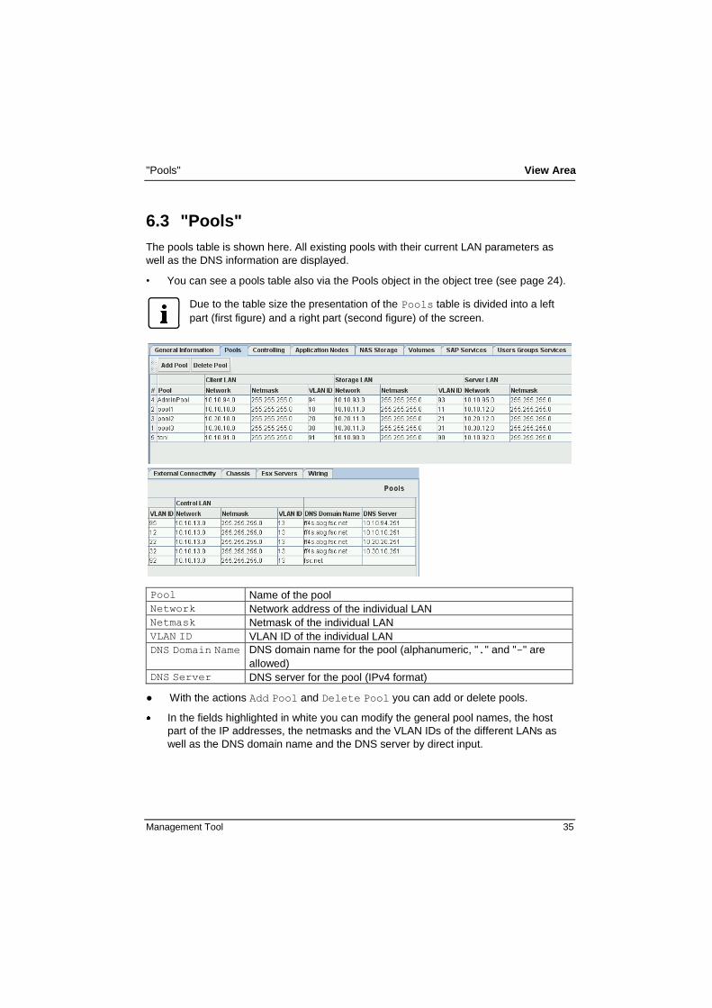
6.3 "Pools"
The pools table is shown here. All existing pools with their current LAN parameters as
well as the DNS information are displayed.
• You can see a pools table also via the Pools object in the object tree (see page 24).
Due to the table size the presentation of the Pools table is divided into a left
part (first figure) and a right part (second figure) of the screen.
Pool Name of the pool
Network Network address of the individual LAN
Netmask Netmask of the individual LAN
VLAN ID VLAN ID of the individual LAN
DNS Domain Name DNS domain name for the pool (alphanumeric, "." and "-" are
allowed)
DNS Server DNS server for the pool (IPv4 format)
● With the actions Add Pool and Delete Pool you can add or delete pools.
In the fields highlighted in white you can modify the general pool names, the host
part of the IP addresses, the netmasks and the VLAN IDs of the different LANs as
well as the DNS domain name and the DNS server by direct input.

View Area "Controlling"
36 Management Tool
Failover concept for Application Nodes related to FA Agents:
If a node in a pool group fails and no adequate spare node is found in the group of the
failed node, the FA Agent can search a spare node in the special pool adminpool. This
pool has a SPARE group, which provides global spare nodes for all pools of a FlexFrame
landscape. The adminpool must not serve as a normal production pool.
6.4 "Controlling"
The controlling table is displayed. In this table the switch groups, the Control Nodes and
associated pools are displayed with their current LAN parameters.
You can open a Controlling table also via the Control Center object concerning
the Control Node entries (see page 19) and via the Network object concerning the
switch group entries (see page 21) in the object tree.
If you open this view via the Control Center object, an additional area is
displayed above the table. Here you can enter miscellaneous settings
concerning the Control Center.
Due to the table size the presentation of the Controlling table is divided into
a left part (first figure) and a right part (second figure) of the screen.

"Controlling" View Area
Management Tool 37
Host Name Name of the component
Type Type of the component
Swg Associated switch group
Pool Associated pool
Host Common host part of all VLAN sements for the component in the
relevant row
Host Name / IP Host name and IP address of the individual LAN
With the actions Add Switch Group and Delete Switch Group you can add or
delete switch groups, see section 8.16, Adding Switch Groups on page 93.
In the Swg column you can change the association of switch groups to Control
Nodes. A left mouse-click on the appropriate field opens a pull-down menu, in which
you can select the desired association.
In the other fields highlighted in white you can modify the host names of the switch
groups and Control Nodes as well as the host parts of the IP addresses of the
different LANs by direct input.

View Area "Application Nodes"
38 Management Tool
6.5 "Application Nodes"
The Application Nodes table is displayed. In this table all existing Application Nodes
of the FlexFrame environment on which the SAP services run are displayed with their
current parameters.
You can display the table also via different sub-entries of the Pools object in the
object tree (see page 24), e.g. the information for a single pool is displayed under Pools - <pool_name> and for a single group under Pools - <pool_name> -
Groups - <group_name>.
If you open this view for a single Application Node via the object Pools -
<pool_name> - Groups - <group_name> - Servers <server_name>,
an additional area is displayed above the table. Here you can enter
miscellaneous settings concerning the Application Node, depending on its type.
This is particularly important for Application Nodes with type ESXVM.
All host names generated are used by FlexFrame system software. These host names
are physical host names and not restricted by SAP conventions like virtual host names.
So they may not be used by SAP applications.
Due to the table size the presentation of the Application Nodes table is
divided into a left part (first figure) and a right part (second figure) of the screen.

"Application Nodes" View Area
Management Tool 39
Host Name Name of the Application Node
Type Type of the Application Node
Swg/Esx Server Associated switch group/Esx server
Pool Associated pool
Group Associated pool group
OS Operating system of the component
Host Common host part of all VLAN sements for the component in the
relevant row
Host Name / IP Host name and IP address of the individual LAN
With the actions Add Application Node and Delete Application Node you
can add or delete Application Nodes.
With the actions Add Group and Delete Group you can add or delete pool groups.
With the action Change to Esx you can change an Application Node to an Esx
server
In the Swg/Esx Server, Pool, Group and OS columns you can change the
association of a switch group or ESX server, pool, pool group and operating system
to an Application Node, respectively. A left mouse-click on the appropriate field
opens a pull-down menu, in which you can select the desired association.
In the other fields highlighted in white you can modify the host names of the
Application Nodes and the host part of the IP addresses of the different LANs by
direct input.

View Area "NAS Storage"
40 Management Tool
6.6 "NAS Storage"
In the NAS Storage table all existing physical Network Attached Storage systems are
displayed with their current parameters.
You can display this table also via the Storage and Storage - NAS objects in the
object tree (see page 23)
Host Name Name of the NAS system
For NAS names only lower case letters should be used because
upper case letters will result in serious problems when applying
administration commands later.
Type Type of the NAS system
(NS-Type = EMC NAS, FAS… = NetApp Filer)
Component Component of the NAS system
(Cs = Control station, DM = Data mover)
Standby local This data mover is standby for all data movers in the same NS-
Type NAS storage device (true) or not (false).

"Volumes" and "Pool / SID Mount" View Area
Management Tool 41
Standby remote This data mover is standby for a remote partner (true) or not
(false). The remote partner can be specified with NS-Type NAS
storage devices via the remote partner link. If the remote partner
fails, the standby data mover takes over all tasks.
Partner Name of the remote partner of this NAS system, if set in the Storage object under Storage – NAS - <NAS_device>
Swg Associated switch group
Pool Associated pool
Host Name / IP Host name and IP address of the individual LAN
With the actions Add NAS and Delete NAS you can add or delete NAS systems.
In the Swg column you can change the association of switch groups to NAS systems.
A left mouse-click on the appropriate field opens a pull-down menu, in which you can
select the desired association.
In the other fields highlighted in white you can modify the host names of the NAS
systems and the host part of the IP addresses of the different LANs by direct input.
6.7 "Volumes" and "Pool / SID Mount"
For a description of the Volumes table, see section 6.7.1 "Volumes" on page 42.
For a description of the Pool /SID mount, see section 6.7.2 "Pool / SID Mount"42

View Area "Volumes" and "Pool / SID Mount"
42 Management Tool
6.7.1 "Volumes"
In this view all existing volumes are displayed with their current parameters.
You can open this view also object dependent via the Storage – NAS - <NAS_name> - [<data_mover>]
object in the object tree (see page 23).
Name Name of the volume
Host Name Name of the NAS system
Component Component of the NAS system on which the volume lies
VolFF Device NAS system is VolFF device (true) or not (false)
In a FlexFrame environment must be exactly one VolFF device
Storage Type Type of the storage system
Type Type of the mount point and the volume
Location Mount path of the volume
With the actions Add Volume and Delete Volume you can add or delete volumes,
see section 8.18, Adding Volumes on page 93.
In the fields highlighted in white you can modify volume names by direct input.
6.7.2 "Pool / SID Mount"
In this table all existing Pool-to-Volume and SID-to-Volume relationships that differ from
the default relationship are displayed with their current parameters.
SID mounts Each SAP instance may mount a volume for its saplog sub-directories
or
for its sapdata sub-directories. This mounting of a volume is
represented here as a relation from an SID specific mount point to a
volume.
Pool mounts Each pool may mount a volume for its sapdata, saplog and for pool
specific volFF sub-directories. This mounting of a volume is also
represented as a relation from a pool specific mount point to a volume.
All this mount relations may point to the same volume.
Sid specific mounts always prevail. If there is no pool specific mount and no sid specific
mount the data will reside in the common volFF.
You can open this view also object dependent via the Storage – NAS - <NAS_name> - [<data_mover>]
object in the object tree (see page 23).

"SAP Services" View Area
Management Tool 43
Mount Type Type of the mount point
Pool Name of the associated pool
SID SID from SAP Services
VolFF /
Sapdata /
Saplog
Path of the related volume
With the actions Add Mount and Delete Mount you can add or delete mount
points of volumes, see section 8.10, Adding Mount Points for Volumes on page 80.
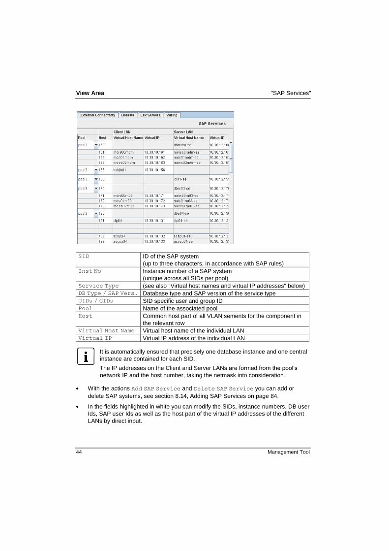
6.8 "SAP Services"
In this table SAP services are displayed with their current parameters.
You can display this table object dependent via the Pools - <pool_name> -
SIDs object in the object tree (see page 24).
Due to the table size the presentation of the SAP Services table is divided
into a left part (first figure) and a right part (second figure) of the screen.
View Area "SAP Services"
44 Management Tool
SID ID of the SAP system
(up to three characters, in accordance with SAP rules)
Inst No Instance number of a SAP system
(unique across all SIDs per pool)
Service Type (see also "Virtual host names and virtual IP addresses" below)
DB Type / SAP Vers. Database type and SAP version of the service type
UIDs / GIDs SID specific user and group ID
Pool Name of the associated pool
Host Common host part of all VLAN sements for the component in
the relevant row
Virtual Host Name Virtual host name of the individual LAN
Virtual IP Virtual IP address of the individual LAN
It is automatically ensured that precisely one database instance and one central
instance are contained for each SID.
The IP addresses on the Client and Server LANs are formed from the pool’s
network IP and the host number, taking the netmask into consideration.
With the actions Add SAP Service and Delete SAP Service you can add or
delete SAP systems, see section 8.14, Adding SAP Services on page 84.
In the fields highlighted in white you can modify the SIDs, instance numbers, DB user
Ids, SAP user Ids as well as the host part of the virtual IP addresses of the different
LANs by direct input.

"SAP Services" View Area
Management Tool 45
Virtual host names and virtual IP addresses
Virtual host names and the corresponding virtual IP addresses are used by applications
to address the server on which an SAP instance is running.
The virtual IP address is assigned to a physical host dynamically before an SAP instance
is started. Thus, it identifies the actual host on which the SAP instance is running. If an
SAP instance is moved to another server, this SAP instance always is addressable using
the same virtual IP address. Virtual IP addresses are also used for communication from
applications outside FlexFrame systems, i.e. SAP front ends such as SAPGUI.
Virtual host names are formed as follows:
<service_type>[<ID>]<SID>[<-LAN_type>]
service_type db
ci
app
ascs
scs
jc
j
lc
ers
mdis
mds
mdss
trx
cms
bobj
smd
database instance
central instance (ABAP)
application instance (ABAP)
ABAP SAP central services instance
JAVA SAP central services instance
JAVA central instance
JAVA application instance
LiveCache instance
Enqueue Replication Service instance
MDM Import Server Instance
MDM Server instance
MDM Syndication Server isntance
TREX Application Server instance
Content Management Service instance
Busines Objects Enterprise instance
Solution Manager Diagnostic agent
ID Instance number from 00 to 96 (except 2, 25, 43, 72 and 89) for the
service type (left empty for db and lc).
SID System ID of an SAP system.
LAN_type -se Server LAN
empty string Client LAN
This host name formation rule for virtual services is mandatory in version ≥4.2A of the
FlexFrame solution. Some components rely on this rule.

View Area "Users Groups Services"
46 Management Tool
6.9 "Users Groups Services"
The "Users Groups Services" table gives you an overview over the Location, the User
Name and User ID of all SAP services in the related scope (pool scope or global scope).
In the fields highlighted in white you can modify the User IDs by direct input.
6.10 "External Connectivity"
With the Management Tool a pool-specific external connectivity can be planned. It leads
to configuration of abstract external connectivity devices. For a pool-independent global
connectivity see page 64.
The switch ports connected to NICs of this external connectivity devices are configured
with untagged VLAN switch ports in case of a single VLAN. In case of multiple VLANs, all
will be configured as tagged. If tagged, devices plugged into these ports require
interfaces using tagged VLANs. To be able to communicate, these VLANs have to be
configured with the same VLAN IDs like the switch port and as configured with the
Management Tool. A link aggregation for load balancing will not work and may block the
entire network!

"External Connectivity" View Area
Management Tool 47
In the External Connectivity table all network connections of the internal FlexFrame
networks to the operator’s corporate network are displayed with their current parameters.
Entries in the various LAN segments may, for example, be necessary for backup servers
or servers outside the FlexFrame environment.
You can open this view also object dependent via the Pools – <pool_name> -
External Connectivity object in the object tree (see page 24).
Due to the table size the presentation of the SAP Services table is divided
into a left part (first figure) and a right part (second figure) of the screen.

View Area "External Connectivity"
48 Management Tool
Host Name Host name of the external device
Swg Associated switch group
Pool Associated pool
NICs Number of NICs
Host Common host part of all VLAN segments for the component in
the relevant row
Host Name / IP Host name and IP address of the individual LAN
With the actions Add External Connectivity and Delete External Connectivity you can
add or delete a connection (see section 8.8, Adding External Connectivities (Pool-
specific) on page 79).
In the Swg column you can change the association of a switch group to the external
device. A left mouse-click on the appropriate field opens a pull-down menu, in which
you can select the desired association.
In the fields highlighted in white you can modify the host names as well as the host
part of the IP addresses of the different LANs by direct input.

Chassis View Area
Management Tool 49
6.11 Chassis
In this table all chassis from the chassis list are listed one after another: SWB, MGMT
blades and server blades in the order of the slots. The slot number is displayed in the
"Slot" column.
Due to the table size the presentation of the Chassis table is divided into a left
part (first figure) and a right part (second figure) of the screen.

View Area Switch Blades
50 Management Tool
6.12 Switch Blades
The view area of a switch blade shows the properties of the switch blade in the upper half
of a split pane and the same information as in the chassis table for this switch blade in
the lower half of the split pane.
Ensure to choose user and password of the switch blade according to the
restrictions in the “User Interface Description” of this switch blade
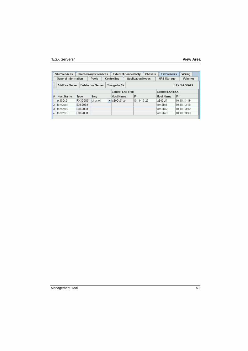
6.13 "ESX Servers"
In this table, all ESX servers are displayed with their current parameters. You can also
add an ESX server, delete an ESX server or change an ESX server to an Application
Node.
"ESX Servers" View Area
Management Tool 51

View Area "Wiring"
52 Management Tool
6.14 "Wiring"
In this document the generated network wiring plan is displayed.
The wiring plan you can find in several places in the object tree, when you right-click add
an optional wiring object this wiring plan will be displayed as related view, showing you
the wiring plan of the objects in the sub-tree.
Places where you can add a Wiring object:
FlexFrame
Storage
Pools – <pool>
Pools – <pool> –- Groups – <group>
Management Tool 53
7 Menu Functions
7.1 Creating a New Configuration
A new configuration can be created in the following three ways:
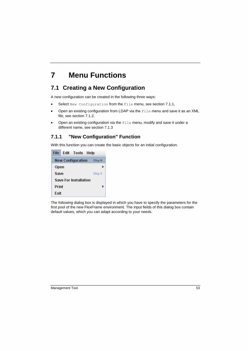
Select New Configuration from the File menu, see section 7.1.1,
Open an existing configuration from LDAP via the File menu and save it as an XML
file, see section 7.1.2.
Open an existing configuration via the File menu, modify and save it under a
different name, see section 7.1.3
7.1.1 "New Configuration" Function
With this function you can create the basic objects for an initial configuration.
The following dialog box is displayed in which you have to specify the parameters for the
first pool of the new FlexFrame environment. The input fields of this dialog box contain
default values, which you can adapt according to your needs.

Menu Functions Creating a New Configuration
54 Management Tool
First Pool Name The name of the first pool.
The name must start with a letter and may only contain
numbers, letters and "-". The pool name becomes part
of an automatically generated host name that may only
be up to 13 characters long in an SAP environment.
Therefore, we recommend that the pool name should
be limited to three characters and written in lower case
letters.
First Group Name The name of the first pool group.
The name must start with a letter and may only contain numbers, letters, "_" or "-".

Creating a New Configuration Menu Functions
Management Tool 55
First Switch Group Name The name of the first switch group.
The name must start with a letter and may only contain
numbers, letters, "_" or "-".
DNS Domain Name The DNS domain name for the first pool.
The name has to conform to RFC1035. This means, the
domain parts have to be separated by a dot and must
consist of alphanumerical characters and dashes. The
parts may not begin with a number or a dash.
DNS Server IPv4 address of the DNS Domain Server for the first
pool. The name has to conform to RFC1035 (see
above). No entry is required for this field. If this field is
empty, fully qualified domain names outside of
FlexFrame cannot be resolved by neither the Control
Nodes nor the Application Nodes.
Network (LANs) The relevant network in IPv4 format. In binary, the
network address must contain a zero at the same
position as the netmask of the individual LAN segments.
The individual networks must be different from each
other.
Netmask (LANs) The relevant netmask in IPv4 format. In the network
section the netmask must consist of binary ones, and in
the host section of binary zeros. You are recommended
to use the same netmask for all network segments.
VLAN ID (LANs) The relevant VLAN ID. The VLAN ID is an integer
between 2 and 4094. The VLAN IDs must be unique
over all LAN segments.
Depending on the actual switching hardware (switch
blades or switchgroup switches) further restrictions may
apply.
Details you will find in the "HW Characteristics
Quickguides" of these devices.
NAS System Pull down menu with valid NAS types, name of the NAS
system and number of NICs (2-8).
After you have competed your input or for the assumption of the default values, click on the OK button. The structured object list for this configuration will be displayed in the
object tree.
Menu Functions Creating a New Configuration
56 Management Tool
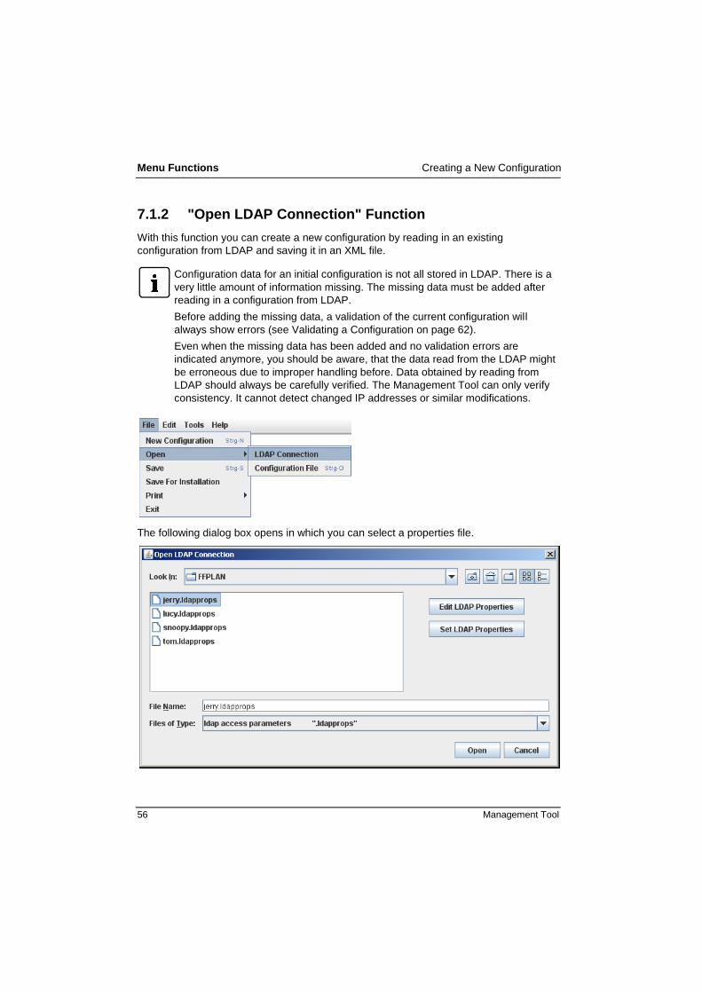
7.1.2 "Open LDAP Connection" Function
With this function you can create a new configuration by reading in an existing
configuration from LDAP and saving it in an XML file.
Configuration data for an initial configuration is not all stored in LDAP. There is a
very little amount of information missing. The missing data must be added after
reading in a configuration from LDAP.
Before adding the missing data, a validation of the current configuration will
always show errors (see Validating a Configuration on page 62).
Even when the missing data has been added and no validation errors are
indicated anymore, you should be aware, that the data read from the LDAP might
be erroneous due to improper handling before. Data obtained by reading from
LDAP should always be carefully verified. The Management Tool can only verify
consistency. It cannot detect changed IP addresses or similar modifications.
The following dialog box opens in which you can select a properties file.

Creating a New Configuration Menu Functions
Management Tool 57
To open an LDAP connection, click on the corresponding file and then click on the Open
button. The structured object list for this configuration will be displayed.
To modify the properties of the selected file, click on the Edit LDAP Properties button.
The following dialog box opens:
Click on Save to save the modified properties.
By clicking on the Set LDAP Properties button the same dialog box is
displayed with blank input fields.
LDAP URL Address of the server for LDAP access.
Base DN The Base DN (Distinguished Name) is the root for the
LDAP name space for this FlexFrame environment.
This can be a subset of a higher LDAP hierarchy. This
field may be empty if the DNS domain name is
specified. If a DNS domain is set and no Base DN
exists, it is formed from the DNS domain when the
Control Nodes are installed. The entry is not checked
for plausibility!
User DN User DN of the LDAP user.
Password Password of the LDAP user.
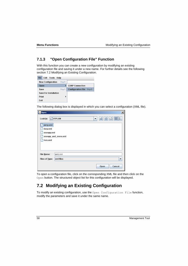
Menu Functions Modifying an Existing Configuration
58 Management Tool
7.1.3 "Open Configuration File" Function
With this function you can create a new configuration by modifying an existing
configuration file and saving it under a new name. For further details see the following
section 7.2 Modifying an Existing Configuration.
The following dialog box is displayed in which you can select a configuration (XML file).
To open a configuration file, click on the corresponding XML file and then click on the
Open button. The structured object list for this configuration will be displayed.
7.2 Modifying an Existing Configuration
To modify an existing configuration, use the Open Configuration File function,
modify the parameters and save it under the same name.

Saving a Configuration Menu Functions
Management Tool 59
7.3 Saving a Configuration
You save a configuration by selecting the Save function.
The following dialog box is displayed in which you can save the new/modified
configuration in an XML file.
To save a new configuration, type <file_name>.xml in the File Name field and click
on the Save button.
To save a modified configuration, click on the corresponding XML file and then click on
the Save button.
The configuration file should be copied under the name ff_config.xml to the root
directory of a blank floppy disk or USB stick. This external medium will be used for the
installation.
Within the Management Tool the file name is arbitrary. For the installation the file
name must be ff_config.xml.

Menu Functions Saving for Installation
60 Management Tool
7.4 Saving for Installation
You save a configuration for an installation by selecting the Save For Installation
function. Save For Installation is nothing but a combined validation and saving
into the file ff_config.xml.
The following dialog box is displayed in which you can save the new/modified
configuration for an installation in an XML file.
The file name ff_config.xml is preset for this name is necessary for installation.
Before saving for installation a validation of the data is performed.
The "Save configuration" dialog box only opens if no error is found.
Warnings are tolerated.

Printing a Configuration Menu Functions
Management Tool 61
7.5 Printing a Configuration
You can print the current settings of the selected configuration by selecting the Print
function. The views of all tabs or the wiring plan are printed.
7.6 Editing a Configuration
With the functions Add and Delete you can execute the same actions, which are offered
as buttons in different views. For more information see chapter "View Area" on page 33.

Menu Functions Validating a Configuration
62 Management Tool
7.7 Validating a Configuration
With the Validate Configuration function yon can check whether the current
configuration is valid and may be used by the installation script.
By clicking this function the following message box displays the check results. You can reduce the output by activating the Show only errors checkbox.
The validation of the data input is done by using the Validate
Configuration function. It is recommended to use the Validate
Configuration function also while entering data to check and correct it, not
only at the end of the complete configuration.
7.8 Generating a Network Wiring Plan
You can generate a network wiring plan automatically or manually. The automatic
generation is recommended because it is the most comfortable and safest method to
generate a correct network wiring plan.
After the network wiring plan is generated, it is displayed under the Wiring tab in the
FlexFrame object view (see page 52).

Generating a Network Wiring Plan Menu Functions
Management Tool 63
7.8.1 Automatic Generation
You generate a network wiring plan automatically with the Perform Wiring function.
Before you generate a network wiring plan with the Perform Wiring function, you
must delete an existing network wiring plan with the Clear Wiring function. Only if
the existing wiring is manually preconfigured and supposed to remain, you may
call Perform Wiring without first resetting it.
All open NICs will be connected automatically to the related switch ports. The icons of the
connected NICs and switch ports are marked green in the object tree (for an example see
the figure in the following section).
If there is more than one switch group these switch groups will be connected to ports of
an abstract network cloud called "Core or Direct". This "Core or Direct" cloud stands for
networking in the responsibility of FlexFrame customer networking environment, not
anymore in the responsibility of FlexFrame. For a device connected to "Core or Direct"
FlexFrame will not configure any ports at FlexFrame switches.
7.8.2 Manual Generation
To modify a network wiring plan manually, navigate to a switch port or a NIC object in the
object tree and select a value from the pull-down menu (see the example below). If the
switch port or NIC is connected, its icon is marked green in the object tree.

Menu Functions Generating Global Connectivity
64 Management Tool
7.9 Generating Global Connectivity
With the Management Tool device independent global connectivity can be planned. It
leads to configuration of abstract external connectivity usually in form of switch ports that
provide access to certain Client LANs.
For a device specific external connectivity see page 46.
The global connectivity is responsible for the global network connections which connect
the internal FlexFrame network with the "outside world" (e.g. corporate network).
After the global connectivity is generated, it is displayed in the object tree (see page 28)
and under the Wiring tab in the FlexFrame object view (see page 52).
7.9.1 Automatic Generation
You generate the global connectivity automatically with the Perform Wiring function.
Before you generate the global connectivity with the Perform Wiring function,
you must delete an existing connectivity with the function Clear Client LAN
Connectivity.
With the automatic generation a standard wiring will be generated analogous to the
following settings in the Network object (see also page 21):
Client LANs on SWG ports = true
One Client VLAN per SWP = false
One common connection with two NICs for all existing pools
Client LANs on SWG ports = true
One Client VLAN per SWP = true
One separate connection with two NICs for each existing pool
Though global connectivity configures only switch ports, NICs are getting involved be-
cause abstract global connectivity objects with NICs are configured in the object tree –
just to visualize with Management Tool means, what the switch ports are used for.

Generating Global Connectivity Menu Functions
Management Tool 65
These abstract global connectivity objects you can imagine as abstract as the further
above mentioned "Core or Direct" networking cloud which stands for networking infra-
structure only in the responsibility of the FlexFrame customer. Here also the switch ports
of the FlexFrame switches are configured by FlexFrame, the abstract global connectivity
is completely in the responsibility of the FlexFrame customer.
7.9.2 Manual Generation
To generate the global connectivity manually, perform the following steps:
1. If the entry Global Connectivity
is not available in the object
tree, create it:
2. Add a Client LAN Connection
entry:
3. Under ClLanCons add (at
least) one Client LAN entry:
A dialog box is opened, in
which you must link the
Client LAN to the desired
pool.
If the desired pool does not exist yet, you can link the Client LAN later after you
have created the pool:

Menu Functions Generating Host Parts of IP Addresses
66 Management Tool
4. To connect the NICs to the related switch ports, execute the Perform Wiring
function (without executing Clear Client LAN Connectivity before), or set the
connection manually (see below):
7.10 Generating Host Parts of IP Addresses
You can generate the host part of the IP addresses of the Client LAN, Server LAN and
Storage LAN automatically or manually. The automatic generation is a comfortable and
safe method to generate IP addresses. The addresses must be unique within a
FlexFrame environment.
An IPv4 address consists of a network section and a host section. In the network
section the netmask consists of binary ones and in the host section of binary
zeros. Example (the host part of the IP address is underlined):
netmask: 255.255.255.0 Host IP: 192.168.100.234
netmask: 255.255.0.0 Host IP: 192.168.100.234

Generating Host Parts of IP Addresses Menu Functions
Management Tool 67
7.10.1 Generate Host Parts Automatically
To generate the host parts automatically, first you have to reset them to a default value
with the Reset All function. Then you can generate them with the Set All function.
7.10.2 Generate Host Parts Manually
You can generate the host parts manually in the view area, by entering the values into
the white highlighted fields of the corresponding columns or when setting the host
property of a selected IP interface object.


Management Tool 69
8 Actions
Actions are performed via action buttons within the views or via context menus (right
mouse click on an object) within the structured object tree.
Add actions always generate a new sub-tree in the structured object tree like storage
objects with their sub-components, Application Nodes with their NICs and LAN addresses
or switch groups.
Add actions, which are invoked for example using the buttons in tables, like the
Application Node table or the Pool table always will show a dialog. This kind of dialogs -
when terminated with the "OK" button - will provide standard FlexFrame device objects
with their sub-trees. In most cases this will be sufficient to configure your FlexFrame
installation.
For a more detailed editing of FlexFrame objects you have to navigate in the structured
object tree to the object you want to modify and edit the properties in the view area or
delete or add objects via the right-click context menu. Like this you can modify default
settings or object sub-trees as they were built using higher level dialogs.
Not all right-click add or delete actions in the object tree will open a dialog box. Some
objects are just added to the object tree with their properties having default values and
you will have to modify these properties later to your needs.
8.1 Overview
The following table gives an overview where actions can be performed.
You can add/delete via button in the
table named: via context menu in the named object
Wiring View
This is a special view
object which displays the
wiring for the
corresponding object in
the view area.
FlexFrame
Storage
Pools – <pool>
Pools – <pool> –- Groups –
<group>
Application Nodes Application Nodes Pools – <pool> – Groups –
<group> – Servers
Esx Servers Esx Servers Esx Server server list
Blade server chassis Chassis Chassis

Actions Overview
70 Management Tool
You can add/delete via button in the
table named: via context menu in the named object
Control stations and
Data movers Storage – NAS – <emc_nas>
Data NICs
Control Center –
<control_node>
Storage – NAS – <filer>
Storage – NAS – <emc_nas> –
DM <n>
Chassis – <blade_server> –
<swb>
Global Connectivity –
Client LAN Connection <n> –
ClLanCons
External connectivites
(pool-specific)
External
Connectivity
Pools – <pool> (first call)
Pools – <pool> – External
Connectivity
(further calls)
LANs
Control LANs
Client LANs
Server LANs
Storage LANs
Storage LANs
Storage LANs
Control Center -
<control_node>
Control Center –
<control_node> –
Client Lans
Control Center – <cn_name> –
Server Lans
Control Center – <cn_name> –
Storage Lans
Storage – NAS – <emc_nas> –
<data_mover> – Storage Lans
Storage – NAS – <filer> –
Storage Lans
Mount points for volumes Pool / SID Mount
NAS systems NAS Storage Storage – NAS
Pool groups Application Nodes Pools – <pool> – Groups
Pools Pools Pools

Context Menu of selected Objects Actions
Management Tool 71
You can add/delete via button in the
table named: via context menu in the named object
SAP instances Pools – <pool> – SIDs – <sid>
– Instances
SAP services SAP Service Pools – <pool> – SIDs
Switches Network – Switch Groups –
<swg> – Switches
Switch groups Controlling Network – Switch Groups
Switch ports Network – Core or Direct –
Ports Core or Direct
Volumes Volumes
Storage – NAS – <emc_nas> –
<data_mover> – Volumes
Storage – NAS – <filer> –
Volumes
With the Delete action you can delete all objects in the object tree.
This action is carried out directly, no safety inquiry will take place!
If you delete an object by mistake, you can repair it:
add it again in the object immediately above or
read it in the configuration file again with the
Open -> Configuration File function.
In the latter case, all input that you made previously is lost (if you did not
accomplish a backup in the meantime).
In case of delete actions which are carried out via a dialog box, you must specify
the object to be deleted. These boxes have all the same structure and are not
described explicitly.
8.2 Context Menu of selected Objects
The context menu of selected objects has the best choice of actions to be performed on
an object. Some possibilities to modify an object you will only find in the context menu of
an object.
Essential context menu functions are “a d d ” and “d e l e t e ”, they are
available in the context of nearly every object
Another important function that is available in the context menu of some object
ist the “c o n v e r t ” function.

Actions Context Menu of selected Objects
72 Management Tool
With the “c o n v e r t ” function you are able to convert objects in compatible
objects while keeping the information in the subtree of the converted objects.
For Netapp NAS devices e.g. this means, that you can convert a specific filer
type to a compatible other filer type and wiring and network addresses are kept
the same

Adding Application Nodes Actions
Management Tool 73
8.3 Adding Application Nodes
The action for adding an Application Node opens a dialog box in which the number and
type of the input fields depend on the selected server.

Actions Adding Application Nodes
74 Management Tool
Type Type of the Application Node.
Pool Pool to which the Application Node belongs.
Group Pool group to which the Application Node belongs.
Host Name Host name of the Application Node.
Switch Group Associated switch group.
OS Operating system
Chassis Slot Slot number of the server blade
10 Gbit Data NICs true / false
If you change the type of the Application Node a dialog box opens saying that the
"AN parameters" are reinitialized.
Just like add actions in general, adding an Application Node generates a new sub-tree in
the structured object tree. You have to navigate to the object representing the Application
Node and select it to activate the associated view, to be able to edit additional properties
of the newly created Application Node. This is particularly important for Application Nodes
of type ESXVM, which denotes a virtual machine on an ESX server.

Adding Application Nodes Actions
Management Tool 75
The upper pane of this view contains virtual machine properties that are set to default
values, but should be adjusted to match the configuration requirements, as well as a link
to the ESX server on which the virtual machine will be created during the installation
process.
Number of virtual
CPUs
Number of CPUs for the virtual machine. Must be a number
between 1 and 8. Moreover, the available resources of the
ESX Server and the intended usage must be taken into
account.
Memory size of
virtual machine
[MB]
Memory size in MB for the virtual machine. Must be a number
between 256 and 261120 (=255GB). Moreover, the available
resources of the ESX Server and the intended usage must be
taken into account.
ESX Server for VM Name of the ESX Server on which the virtual machine is
created

Actions Adding Blade Server Chassis
76 Management Tool
8.4 Adding Blade Server Chassis
The action for adding a blade server chassis opens the following dialog box.
Type Type of the blade chassis.
Host Name Host name of the blade chassis.
Switch Group Associated switch group.
Switch Blade Type Type of the switch blade
If you delete a blade server chassis the Application Nodes or ESX severs that are our
FlexFrame representative of this server blades still exist. These Application Nodes or
ESX just won’t be related anymore to a chassis via the Connector and Slot objects.
Depending on the Chassis Type – Switch Blade Type combination, due to the actual
availability, the input for "10 GBit Data NICs" and / or "Number of NICs" may by disabled
or not visible at all.
To assign a server blade to a new / different chassis do the following::
Activate a connector in the sub-tree of the server blade.
Select a new chassis slot corresponding to another blade server chassis.

Adding Control Stations Actions
Management Tool 77
8.5 Adding Control Stations
The action for adding a control station is only available with NS-Type NAS storage
devices. It is carried out directly, no dialog box is opened. Max. 2 control stations can be
present.
8.6 Adding Data Movers
Add DM is carried out with a right mouse click on a
NAS storage device in the object tree
The action for adding a data mover is only available
with NS-Type NAS storage devices.
The action opens the following dialog box. Max. 8 data mover can be present.

Actions Adding Data NICs
78 Management Tool
Name Name of the data mover.
volFF Device NAS system is VolFF device (true) or not (false).
In a FlexFrame environment must be exactly one VolFF device.
Remote Standby
Data Mover
This data mover is standby for a remote partner (true) or not
(false). The remote partner can be specified with NS-Type
NAS storage devices via the remote partner link. If the remote
partner fails, the standby data mover takes over all tasks.
Local Standby
Data Mover
This data mover is standby for all data movers in the same NS-
Type NAS storage device (true) or not (false).
Note:
Only one of both standby data movers can be set to true.
8.7 Adding Data NICs
The action for adding a data NIC is carried out directly, no dialog box is opened. The
following list shows the admissible range for the number of NICs that can be present for
the different types of Network Attached Storage:
2 1GbE NICs 16 or alternatively exactly 2 NICs of 10GbE type for the different
NetApp FASxxxx filer families (the exact maximum varies between the familiy types)
2 1GbE NICs 6 for all different types of EMC Celerra data movers
All interfaces used in FlexFrame are of the same type, either homogeneously 1GbE
or homogeneously 10GbE

Adding External Connectivities (Pool-specific) Actions
Management Tool 79
8.8 Adding External Connectivities (Pool-specific)
The action for adding a pool-specific external connectivity opens the following dialog box.
Procedure when adding an external device via context menu in the object tree:
With the first call of the action under Pools – <pool> the object External
Connectivity is created and the first device is added. Further devices can be
added then under Pools – <pool> – External Connectivity with
Add – External Device.
Default for External Connectivities are 1 GBit ports. If you need External
Connectivites with 10 GBit ports you have to navigate in the object tree to the
“DataNICs” of the External Connectivity, “right click delete” the 1GBit DataNICs
and “right click add” 10 GBit DataNICs instead.
Host Name Host name of the external device.
Client LAN
Storage LAN
Server LAN
Control LAN
Choice of the LANs which should be visible outside FlexFrame.
Pool Name of the associated pool.
Switch Group Associated switch group.
Number of NICs Number of NICs.

Actions Adding LAN Interfaces
80 Management Tool
8.9 Adding LAN Interfaces
The action for adding a LAN interface opens the following dialog box. Depending on the
selected object, this can be the interface for a Control LAN (max. 2 can be present), a
Client LAN, a Server LAN or a Storage LAN.
LAN Selection of the appropriate LAN
Host Host part of the IP address of the LAN
8.10 Adding Mount Points for Volumes
The action for adding a mount point for a volume opens the following dialog box.
Mount points exist for pool objects and for the database objects in the sub-tree of SID
objects. For the database objects you can add sapdata and saplog mount points and
for pools in addition to this two mount points you can add a volFF mount point.
With Mount Point objects you can relate a mount point object to Volume. For FlexFrame
this just means that you mount e.g. sapdata for the given SID / Pool directory from the
specified volume of the filer that it resides on.
Mount Point Object tree path of the mount point.
Volume Path Object tree path of the volume.
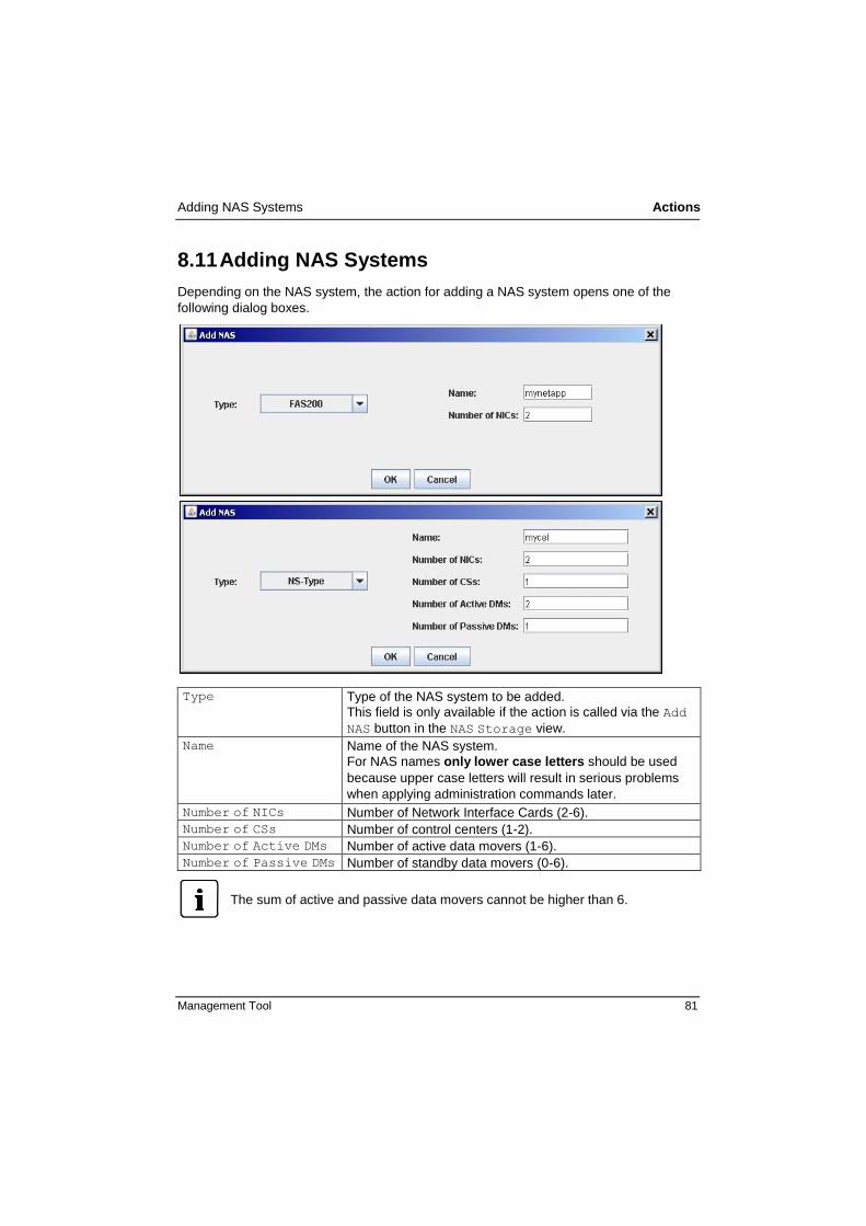
Adding NAS Systems Actions
Management Tool 81
8.11 Adding NAS Systems
Depending on the NAS system, the action for adding a NAS system opens one of the
following dialog boxes.
Type
Type of the NAS system to be added.
This field is only available if the action is called via the Add
NAS button in the NAS Storage view.
Name Name of the NAS system.
For NAS names only lower case letters should be used
because upper case letters will result in serious problems
when applying administration commands later.
Number of NICs Number of Network Interface Cards (2-6).
Number of CSs Number of control centers (1-2).
Number of Active DMs Number of active data movers (1-6).
Number of Passive DMs Number of standby data movers (0-6).
The sum of active and passive data movers cannot be higher than 6.

Actions Adding Pool Groups
82 Management Tool
8.11.1 Celerra SRDF-NAS Active/Passive Configuration
In order to build a disaster tolerant FlexFrame configuration with SRDF mirrored EMC
NAS systems, a special type of Celerra SRDF-NAS active/passive configuration has to
be defined by applying the following procedure:
The active Celerra must be the one that has an active data mover which is the volFF
device of the FlexFrame landscape. This system must be defined in a first step (Add
NAS dialog) including storage LAN addresses and volumes for its active data movers.
This Celerra system will also have at least one local standby data mover, which must
be defined with no storage LAN addresses and no volumes, and has the property
Local standby datamover set to true.
Add the passive Celerra in a next step. The passive Celerra must have a number of
RDF standby data movers equal to the sum of the number of active data movers that
need to be protected by SRDF and their associated local standby data movers of the
active Celerra. This attribute cannot be set directly in the Add NAS dialog. Instead,
add the Celerra with the correct total number of data movers. Then set the Remote
partner property of this Celerra to point to the active Celerra. You can do this in the
Remote partner drop-down box in the view that is displayed when selecting the
passive Celerra in the object tree. Now you can set the Remote standby
datamover property to true for each data mover that will be used as an RDF
standby in the view that is displayed when selecting the concerned data mover in the
object tree. These data movers must also be defined with no storage LAN addresses
and no volumes.
8.12 Adding Pool Groups
The action for adding a pool group opens the following dialog box.
Pool Host name of the pool.
Group Name Associated group.

Adding Pools Actions
Management Tool 83
8.13 Adding Pools
The action for adding a pool opens the following dialog box.
Pool Name Name of the new pool.
The name must start with a letter and may only contain numbers,
letters and "-". The pool name becomes part of an automatically
generated host name that may only be up to 13 characters long
in an SAP environment. Therefore, we recommend that the pool
name should be limited to three characters and written in lower
case letters.
Group Name Name of the first group within the pool.
The name must start with a letter and may only contain numbers,
letters, "_" or "-".
DNS Domain Name DNS domain name for the pool.
The name has to be conform to RFC1035. This means, the
domain parts have to be separated by a dot and must consist of
alphanumerical characters and dashes. The parts may not begin
with a number or a dash.
DNS Server DNS Domain Server for the pool (IPv4 format).
The name has to be conforming to RFC1035 (see above).

Actions Adding SAP Services
84 Management Tool
Network (LANs)
Relevant network in IPv4 format.
In binary, the network address must contain a zero at the same
position as the netmask of the individual LAN segments. The
individual networks must be different from each other.
Netmask (LANs)
Relevant netmask in IPv4 format.
In the network section the netmask must consist of binary ones,
and in the host section of binary zeros. You are recommended to
use the same netmask for all network segments.
VLAN ID (LANs)
Relevant VLAN ID.
The VLAN ID is an integer between 2 and 4094. The VLAN IDs
must be unique over all LAN segments.
Depending on the switching hardware (switch blades or
switchgroup switches) further restrictions may apply. For details
see the "HW Characteristics Quickguides" of these devices.
There is only one common Control LAN even though in the Pools table a
Control LAN displayed for each pool.
8.14 Adding SAP Services
The action for adding a SAP service opens the following dialog box with 7 tabs for
different service types.
Classic, page 85
LC, page 86
BOBJ, page 87
CMS, page 88
TRX, page 89
MDM, page 90
SMD, page 91

Adding SAP Services Actions
Management Tool 85
8.14.1.1 Classic
SID SAP system ID (up to three characters, in
accordance with SAP rules).
Number of Instances Number of SAP instances.
Configuration Configuration type of SAP instances.
Pool Name of the associated pool.
OS Operating system
SAP Version SAP version.
DB Type and Version Type and version of the database.
Classic Service Uids SID specific user IDs and group IDs
(depending on the selected DB type).

Actions Adding SAP Services
86 Management Tool
8.14.1.2 LC
The dialog box for the LiveCache service type (LC) is widely conform to the
dialog box for the Classic service type. The only differences are the missing
fields Configuration and Number of Instances.

Adding SAP Services Actions
Management Tool 87
8.14.1.3 BOBJ
SID SAP system ID (up to three characters, in
accordance with SAP rules).
Pool Name of the associated pool.
OS Operating system (optional)
SAP Version SAP version.
BOBJ Service Uids SID specific user IDs and group IDs
(depending on the selected DB type).

Actions Adding SAP Services
88 Management Tool
8.14.1.4 CMS
SID SAP system ID (up to three characters, in
accordance with SAP rules).
Pool Name of the associated pool.
OS Operating system
SAP Version SAP version.
DB Type and Version Type and version of the database.
CMS Service Uids SID specific user IDs and group IDs
(depending on the selected DB type).
The central feature of the CMS is that it is designed to be compatible with different types
of storage media. The CMS works as an interface between content servers and the
SAP System

Adding SAP Services Actions
Management Tool 89
8.14.1.5 TRX
SID SAP system ID (up to three characters, in
accordance with SAP rules).
Number of Instances Number of SAP instances.
Pool Name of the associated pool.
OS Operating system (optional)
SAP Version SAP version.
TRX Service Uids SID specific user IDs and group IDs
(depending on the selected DB type).
TRX finds information in unstructured and structured data. TRX provides SAP
applications with services for searching and classifying large collections of documents
and for searching and aggregating business objects.

Actions Adding SAP Services
90 Management Tool
8.14.1.6 MDM
SID SAP system ID (up to three characters, in
accordance with SAP rules).
Pool Name of the associated pool.
OS Operating system (optional)
SAP Version SAP version.
DB Version Type and version of the database.
Instance Number MDMS / MDS /
MDSS
Instance numbers.
MDM Service Uids SID specific user IDs and group IDs
(depending on the selected DB type, conform to
classic SAP system spec).

Adding SAP Services Actions
Management Tool 91
8.14.1.7 SMD
SID SAP system ID (up to three characters, in
accordance with SAP rules).
Number of Instances Number of SAP instances.
Pool Name of the associated pool.
OS Operating system
SAP Version SAP version. (optional)
DB Type and Version Type and version of the database.
SMD Service Uids SID specific user IDs and group IDs
(depending on the selected DB type).
The solution Manager Diagnostic Agent is the remote component of the E2E Root Cause
Analysis. It performs a connection between SAP Solution Manager (as the managing
system) and the managed system(s). It gathers information from the managed system(s)
and reports them to the SAP Solution Manager.
Modifying the instance the number of instances for a SAP Service:
Every service knows what instances may be modified in the instance list of a
SID. These kinds of instances / actions are offered in the right-click context
menu of the instance list object / instance.

Actions Adding Switches
92 Management Tool
8.15 Adding Switches
The action for adding a switch opens the following dialog box.
Adding a switch is carried out via the Network object in the object tree.
Number of Switches Number of switches within the group. At least two switches
have to be configured in a switch group to provide network
redundancy. The upper limit is currently nine switches.
Switch Type The switch type of each switch within the group. Knowledge
of the precise name of each switch type is required to create
the cabling plan and the switch configurations.
WARNING: If you are building a stack of more than 4 Cisco 3750E switches:
In order to make sure, that this stack is dimensioned well for the planned
FlexFrame configuration, you should consult the FTS configuration and sizing
team in Walldorf before completion of configuration design.

Adding Switch Groups Actions
Management Tool 93
8.16 Adding Switch Groups
The action for adding a switch group opens the following dialog box.
Switch Group Name Name of the new switch group.
Number of Switches See description under Adding Switches above.
Switch Type See description under Adding Switches above.
8.17 Adding Switch Ports
The action for adding a switch port is carried out directly, no dialog box is opened.
8.18 Adding Volumes
The action for adding a volume opens the following dialog box.
NAS Device Name of the NAS system which contains the volume.
Volume Name Name of the volume (max 32 signs, only letters and numbers, have to start with a letter, volFF is not allowed).
Actions Adding Volumes
94 Management Tool
A local standby or remote standby data mover must not possess volumes. This will be
checked when validating the configuration by using the Validate Configuration
function.
If a local standby or remote standby data mover already possesses volumes, you have to
delete the corresponding volumes:
1. Right-click on the volume and select Delete
2. Add them to an active data mover.
If the volume has mount points, e.g. for SID specific sapdata, saplog, then you have to
proceed with Adding Mount Points for Volumes as described in section 8.10, like
you did it with the original volume earlier.

Management Tool 95
9 Abbreviations
ABAP Advanced Business Application Programming
ACC Adaptive Computing Controller
ACI Adaptive Computing Infrastructure
ACPI Advanced Configuration and Power Interface
APM Advanced Power Management
APOLC Advanced Planner & Optimizer Life Cache
CCU Console Connection Unit
CIFS Common Internet File System
DART Data Access in Real Time
DHCP Dynamic Host Configuration Protocol
DIT Domain Information Tree
ERP Enterprise Resource Planning
ESF Enhanced System Facility
EULA End User License Agreement
FAA FlexFrame Autonomous Agent
FC Fiber Channel
FSC FlexFrame Software Container, name part used for
Images and CDs/DVDs
FTP File Transfer Protocol
IP Internet Protocol
LAN Local Area Network
LDAP Lightweight Directory Access Protocol
LUN Logical Unit Number
MAC Media Access Control
MINRA Minimal Read Ahead
NAS Network Attached Storage
NDMP Network Data Management Protocol
NFS Network File System

Abbreviations
96 Management Tool
NIC Network Interface Card
NVRAM Non-Volatile Random Access Memory
OBP Open Boot Prom
OLTP On-Line Transaction Processing
ONTAP Open Network Technology for Appliance Products
OSS Open Source Software
POST Power-On Self Test
PFS Production File System (on Celerra)
PXE Preboot Execution Environment
PY PRIMERGY
QA Quality Assurance
QS Quality of Service
RAID Redundant Array of Independent (or Inexpensive) Disks
RARP Reverse Address Resolution Protocol
RDBMS Relational Database Management System
RHEL Red Hat Enterprise Linux
SCS System Console Software
SAP BW SAP Business Warehouse
SAPGUI SAP Graphical User Interface
SAPOSS SAP Online System Service
SID System Identifier
SLD System Landscape Directory
SLES SUSE Linux Enterprise Server
SMB Server Message Block
SMC System Management Console
SNMP Simple Network Management Protocol
SWG Switch Group
SWP Switch Port
SPOC Single Point Of Control
Abbreviations
Management Tool 97
TELNET Telecommunications Network
TFTP Trivial File Transfer Protocol
UDP User Datagram Protocol
UPS Uninterruptible Power Supply
VLAN Virtual Local Area Network
VTOC Virtual Table Of Contents
WAN Wide Area Network
WAS Web Application Server
WAFL Write Anywhere File Layout
XSCF Extended System Control Facility

Management Tool 99
10 Glossary
Adaptive Computing Controller
SAP system for monitoring and controlling SAP environments.
Advanced Business Application Programming
Proprietary programming language of SAP.
Advanced Power Management
Advanced Power Management defines a layer between the hardware and the
operating system that effectively shields the programmer from hardware details.
Application Agent
A software program for monitoring and managing applications.
Application Node
A host for applications (e.g. SAP instances db, ci, agate, wgate, app etc.). This
definition includes Application Servers as well as Database Servers.
Automounter
The automounter is an NFS utility that automatically mounts directories on an NFS
client as they are needed, and unmounts them when they are no longer needed.
Autonomous Agent
Central system management and high availability software component of FlexFrame.
Blade
A special form factor for computer nodes.
BladeRunner
The working title for the solution part of SAP for FlexFrame.
BOOTPARAM
Boot time parameters of the kernel.
BRBACKUP
SAP backup and restore tools.
Celerra
NAS system of EMC.
Checkpoint Restore
On EMC Celerra a SnapSure feature that restores a PFS to a point in time using
checkpoint information. As a precaution, SnapSure automatically creates a new
checkpoint of the PFS before it performs the restore operation.
Client LAN
Virtual network segment within FlexFrame, used for client-server traffic.

Glossary
100 Management Tool
Common Internet File System
A protocol for the sharing of file systems (same as SMB).
Computing Node
From the SAP ACI perspective: A host that is used for applications.
Control Agent
A software program for monitoring and managing nodes within FlexFrame.
Control LAN
Virtual network segment within FlexFrame, used for system management traffic.
Control Node
A physical computer system, controlling and monitoring the entire FlexFrame
landscape and running shared services in the rack (dhcp, tftp, ldap etc.).
Control Station
A Control Node in an SAP ACI environment.
DART
Operating system of Celerra data movers (Data Access in Real Time).
Dynamic Host Configuration Protocol
DHCP is a protocol for assigning dynamic IP addresses to devices on a network.
Dynamic Host Configuration Protocol server
A DHCP server provides configuration parameters specific to the DHCP client host,
required by the host to participate on the Internet.
EMC NAS
Network attached storage for file systems of EMC.
Enterprise Resource Planning
Enterprise Resource Planning systems are management information systems that
integrate and automate many of the business practices associated with the
operations or production aspects of a company.
Ethernet
A Local Area Network which supports data transfer rates of 10 megabits per second.
Fiber Channel
Fiber Channel is a serial computer bus intended for connecting high-speed storage
devices to computers.
Filer
Network attached storage for file systems of NetApp.
FlexFrame
A joint project in which the main partners are SAP, Network Appliance, Intel and
Fujitsu.
Glossary
Management Tool 101
FlexFrameTM
for SAP®
FlexFrameTM
for SAP® is a radically new architecture for SAP environments. It
exploits the latest business-critical computing technology to deliver major cost
savings for SAP customers.
FlexFrame internal LAN Switch
Cisco network switches which are integral part of the FlexFrame for SAP hardware
configuration and which are automatically configured by the FlexFrame for SAP
software.
Gigabit Ethernet
A Local Area Network which supports data transfer rates of 1 gigabit (1,000
megabits) per second.
Host name
The name of a node (assigned to an interface) that is resolved to a unique IP
address. One node can have multiple host names (cf. node name).
In SAP environments host names are currently limited to 13 alphanumeric characters
including the hyphen (" - "). The first character must be a letter. In the SAP
environment host names are case-sensitive.
Image
In the FlexFrame documentation, "Image" is used as a synonym for "Hard Disk
Image".
Internet Protocol Address
A unique number used by computers to refer to each other when sending information
through networks using the Internet Protocol.
Lightweight Directory Access Protocol
Protocol for accessing on-line directory services.
Local Area Network
A computer network that spans a relatively small area. Most LANs are confined to a
single building or group of buildings. However, one LAN can be connected to other
LANs over any distance via telephone lines and radio waves. A system of LANs
connected in this way is called a Wide Area Network (WAN).
Local host name
The name of the node (physical computer); it can be displayed and set using the
command /bin/hostname.
Logical Unit Number
An address for a single (SCSI) disk drive.
MAC address
Device identifier number of a Network Interface Card. In full: "media access control
address".

Glossary
102 Management Tool
MaxDB
A relational database system from mySQL (formerly ADABAS and SAPDB).
Media Access Control address
An identifier for network devices, usually unique. The MAC address is stored
physically on the device.
NAS system
Network Attached Storage of any vendor (in our context: EMC NAS or NetApp Filer).
NDMPcopy
NDMPcopy transfers data between Filers using the Network Data Management
Protocol (NDMP).
Netboot
A boot procedure for computers where the operating system is provided via a
network instead of local disks.
Netweaver
SAP NetWeaver is the technical foundation of SAP solutions.
Network Appliance Filer
See "Filer".
Network Attached Storage
A data storage device that is connected via a network to one or multiple computers.
Network File System
A network protocol for network-based storage access.
Network Interface Card
A hardware device that allows computer communication via networks.
Node
A physical computer system controlled by an OS.
Node name
The name of a physical node as returned by the command uname -n. Each node
name within a FlexFrame environment must be unique.
Non-Volatile Random Access Memory
A type of memory that retains its contents when the power is turned off.
On-Line Transaction Processing
Transaction processing via computer networks.
OpenLDAP
An Open Source LDAP Service Implementation.
Open Network Technology for Appliance Products
The operating system of Network Appliance Filers.

Glossary
Management Tool 103
Open Source Software
Software that is distributed free of charge under an open source license, such as the
GNU Public License.
Oracle RAC
A cluster database by Oracle Corporation.
Physical host
Name of a physical computer system (node).
Power-On Self Test
Part of a computer's boot process; automatic testing of diverse hardware
components.
Preboot Execution Environment
An environment that allows a computer to boot from a network resource without
having a local operating system installed.
PRIMERGY
Fujitsu's i386-based server product line.
Red Hat Enterprise Linux
Linux distribution by Red Hat, Inc., targeting business customers.
Reverse Address Resolution Protocol
A protocol allowing resolution of an IP address corresponding to a MAC address.
SAP Service
In FlexFrame: SAP Service and DB Services.
SAP service script
An administration script for starting and stopping an SAP application on a virtual host.
SAP Solution Manager
Service portal for the implementation, operation and optimization of an SAP solution.
SAPLogon
Front-end software for SAPGUI.
SAPRouter
Router for SAP services like SAPGUI or SAPTELNET.
SavVol
A Celerra volume to which SnapSure copies original point-in-time data blocks from
the PFS before the blocks are altered by a PFS transaction.
Server
A physical host (hardware), same as node.
Service
A software program providing functions to clients.

Glossary
104 Management Tool
Service type
The type of an application or service (db, ci, app, agate, wgate etc.).
Single Point of Control
In FlexFrame: One user interface to control a whole FlexFrame environment.
Storage LAN
A virtual LAN segment within a FlexFrame environment, carrying the traffic to NAS
systems.
SUSE Linux Enterprise Server
A Linux distribution by Novell, specializing in server installations.
Telecommunications Network
A terminal emulation program for TCP/IP networks such as the Internet.
Trivial File Transfer Protocol
A simple form of the File Transfer Protocol (FTP). TFTP uses the User Datagram
Protocol (UDP) and provides no security features. It is often used by servers to boot
diskless workstations, X-terminals, and routers.
TFTP server
A simple FTP implementation.
Virtual host
The name of the virtual host on which an application runs; it is assigned to a physical
node when an application is started.
Virtual Local Area Network
A VLAN is a logically segmented network mapped over physical hardware according
to the IEEE 802.1q standard.
Virtualization
Virtualization means the separation of hardware and processes. In a virtualized
environment (FlexFrame), a process can be moved between hardware nodes while
staying transparent to the user and application.

Management Tool 105
11 Index
A
abbreviations 95
actions 69
add application node 73
add blade server chassis 76
add control station 77
add data mover 77
add data NIC 78
add external connectivity 79
add group 82
add LAN 80
add mount 80
add NAS 81
add pool 83
add SAP service 84
add switch 92
add switch group 93
add switch port 93
add volume 93
overview 69, 71
application node
add 73
application nodes table 38
assign blade server to chassis 76
B
blade server
assign to chassis 76
blade server chassis
add 76
BOBJ 87
C
chassis object 30
chassis table 49
Classic 85
CMS 88
configuration
create 15, 53
edit 61
modify 58
print 61
save 59
validate 62
validation 15
control center
settings 19
control center object 19
control station
add 77
controlling table 36

Index
106 Management Tool
create new configuration 15
D
data mover
add 77
data NIC
add 78
document history 2
E
error logging 14
ESX parameters 29
ESX servers object 28
ESX servers table 50
external connectivity
add 79
external connectivity table 46
F
failover concept for AN 36
FlexFrame object 18
functions
edit 61
IP addresses
reset all 67
new configuration 53
open configuration file 58
open LDAP connection 56
perform wiring 62, 64
print 61
save 59
save for installation 60
validate configuration 62
G
general information 34
global connectivity object 31
global connectivity, generate 64
glossary 99
group
add 82
H
host names 9
host parts
generate 66
generate automatically 67
generate manually 67
I
installation
save 60
IP addresses
reset 67
L
LAN
add 80
LC 86
M
Management Tool
exit 11
screen layout 12
starting 11
MDM 90

Index
Management Tool 107
menu functions 53
mount
add 80
N
NAS
add 81
NAS storage table) 40
network concept 5
network object 21
network settings 22
network wiring plan, generate 62
new configuration 53
notational conventions 2
NTP master server 20
O
object tree 17
open configuration file 58
open LDAP connection 56
P
pool
add 83
pool / SID mount 41
pool mount 42
pools object 24
pools table 35
R
related documents 3
S
SAP service
add 84
BOBJ 87
Classic 85
CMS 88
LC 86
MDM 90
SMD 91
TRX 89
SAP services 43
SID mount 42
SMD 91
storage object 23
sub-object tree 26
switch
add 92
switch group
add 93
switch port
add 93
switch ports 46
T
tabs
volumes 41
tagged VLAN 46
TRX 89
U
users groups services table 46
V
vCenter 29
Index
108 Management Tool
view area 33
virtual host names) 45
virtual IP addresses 45
VLAN
host names 9
VLAN IDs 46
volume
add 93
volumes 41
volumes (tab) 41
volumes table 42
W
wiring 52