Embed Size (px)
Citation preview

FLENDER couplings
FLENDER RUPEX®couplingsTypes RWN, RWS, RWB, RBSand RFN, RFS
Operating instructionsBA 3600 en 02/2016
2 / 28BA 3600 en 02/2016
FLENDER RUPEX®couplings
Types RWN, RWS, RWB, RBSand RFN, RFS
Operating instructions
Translation of the original operating instructions
Technical data
Declarations
Stocking spare parts
Maintenanceand repair
Faults, causesand remedy
Start-upand operation
Fitting
Notes
1
8
7
6
5
4
3
2
3 / 28BA 3600 en 02/2016
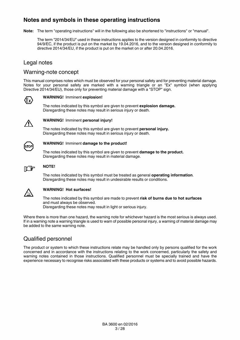
Notes and symbols in these operating instructions
Note: The term "operating instructions" will in the following also be shortened to "instructions" or "manual".
The term "2014/34/EU" used in these instructions applies to the version designed in conformity to directive94/9/EC, if the product is put on the market by 19.04.2016, and to the version designed in conformity todirective 2014/34/EU, if the product is put on the market on or after 20.04.2016.
Legal notes
Warning-note concept
This manual comprises notes which must be observed for your personal safety and for preventing material damage.Notes for your personal safety are marked with a warning triangle or an "Ex" symbol (when applyingDirective 2014/34/EU), those only for preventing material damage with a "STOP" sign.
WARNING! Imminent explosion!
The notes indicated by this symbol are given to prevent explosion damage.Disregarding these notes may result in serious injury or death.
WARNING! Imminent personal injury!
The notes indicated by this symbol are given to prevent personal injury.Disregarding these notes may result in serious injury or death.
WARNING! Imminent damage to the product!
The notes indicated by this symbol are given to prevent damage to the product.Disregarding these notes may result in material damage.
NOTE!
The notes indicated by this symbol must be treated as general operating information.Disregarding these notes may result in undesirable results or conditions.
WARNING! Hot surfaces!
The notes indicated by this symbol are made to prevent risk of burns due to hot surfacesand must always be observed.Disregarding these notes may result in light or serious injury.
Where there is more than one hazard, the warning note for whichever hazard is the most serious is always used.If in a warning note a warning triangle is used to warn of possible personal injury, a warning of material damage maybe added to the same warning note.
Qualified personnel
The product or system to which these instructions relate may be handled only by persons qualified for the workconcerned and in accordance with the instructions relating to the work concerned, particularly the safety andwarning notes contained in those instructions. Qualified personnel must be specially trained and have theexperience necessary to recognise risks associated with these products or systems and to avoid possible hazards.
4 / 28BA 3600 en 02/2016
Intended use of Siemens products
Observe also the following:
Siemens products must be used only for the applications provided for in the catalogue and the relevanttechnical documentation. If products and components of other makes are used, they must berecommended or approved by Siemens. The faultfree, safe operation of the products calls for propertransport, proper storage, erection, assembly, installation, startup, operation and maintenance. Thepermissible ambient conditions must be adhered to. Notes in the relevant documentations must beobserved.
Trademarks
All designations indicated with the registered industrial property mark ® are registered trademarks of Siemens AG.Other designations used in these instructions may be trademarks the use of which by third parties for their ownpurposes may infringe holders’ rights.
Exclusion of liability
We have checked the content of the instructions for compliance with the hard and software described.Nevertheless, variances may occur, and so we can offer no warranty for complete agreement. The informationgiven in these instructions is regularly checked, and any necessary corrections are included in subsequent editions.
Note on the EC Machinery Directive 2006/42/EC
Siemens couplings in the "FLENDER couplings" product range must be treated as "components" in the senseof the EC Machinery Directive 2006/42/EC.Therefore, Siemens needs not issue a declaration of incorporation.Information on safe fitting, safe startup and safe operation can be found in this instructions manual; in additionthe "warningnote concept" therein must be observed.
5 / 28BA 3600 en 02/2016
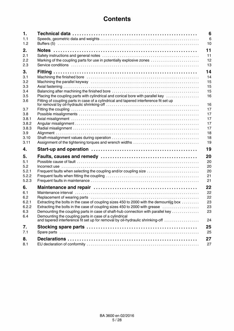
Contents
1. Technical data 6. . . . . . . . . . . . . . . . . . . . . . . . . . . . . . . . . . . . . . . . . . . . . . . . . . . . .1.1 Speeds, geometric data and weights 6. . . . . . . . . . . . . . . . . . . . . . . . . . . . . . . . . . . . . . . . . . . . . . . . . . .1.2 Buffers (5) 10. . . . . . . . . . . . . . . . . . . . . . . . . . . . . . . . . . . . . . . . . . . . . . . . . . . . . . . . . . . . . . . . . . . . . . . . .
2. Notes 11. . . . . . . . . . . . . . . . . . . . . . . . . . . . . . . . . . . . . . . . . . . . . . . . . . . . . . . . . . . . .2.1 Safety instructions and general notes 11. . . . . . . . . . . . . . . . . . . . . . . . . . . . . . . . . . . . . . . . . . . . . . . . . .2.2 Marking of the coupling parts for use in potentially explosive zones 12. . . . . . . . . . . . . . . . . . . . . . . . .2.3 Service conditions 13. . . . . . . . . . . . . . . . . . . . . . . . . . . . . . . . . . . . . . . . . . . . . . . . . . . . . . . . . . . . . . . . . .
3. Fitting 14. . . . . . . . . . . . . . . . . . . . . . . . . . . . . . . . . . . . . . . . . . . . . . . . . . . . . . . . . . . . .3.1 Machining the finished bore 14. . . . . . . . . . . . . . . . . . . . . . . . . . . . . . . . . . . . . . . . . . . . . . . . . . . . . . . . . .3.2 Machining the parallel keyway 15. . . . . . . . . . . . . . . . . . . . . . . . . . . . . . . . . . . . . . . . . . . . . . . . . . . . . . . .3.3 Axial fastening 15. . . . . . . . . . . . . . . . . . . . . . . . . . . . . . . . . . . . . . . . . . . . . . . . . . . . . . . . . . . . . . . . . . . . . .3.4 Balancing after machining the finished bore 15. . . . . . . . . . . . . . . . . . . . . . . . . . . . . . . . . . . . . . . . . . . . .3.5 Placing the coupling parts with cylindrical and conical bore with parallel key 16. . . . . . . . . . . . . . . . .3.6 Fitting of coupling parts in case of a cylindrical and tapered interference fit set up
for removal by oilhydraulic shrinkingoff 16. . . . . . . . . . . . . . . . . . . . . . . . . . . . . . . . . . . . . . . . . . . . . . . .3.7 Fitting the coupling 17. . . . . . . . . . . . . . . . . . . . . . . . . . . . . . . . . . . . . . . . . . . . . . . . . . . . . . . . . . . . . . . . . .3.8 Possible misalignments 17. . . . . . . . . . . . . . . . . . . . . . . . . . . . . . . . . . . . . . . . . . . . . . . . . . . . . . . . . . . . . .3.8.1 Axial misalignment 17. . . . . . . . . . . . . . . . . . . . . . . . . . . . . . . . . . . . . . . . . . . . . . . . . . . . . . . . . . . . . . . . . .3.8.2 Angular misalignment 17. . . . . . . . . . . . . . . . . . . . . . . . . . . . . . . . . . . . . . . . . . . . . . . . . . . . . . . . . . . . . . . .3.8.3 Radial misalignment 17. . . . . . . . . . . . . . . . . . . . . . . . . . . . . . . . . . . . . . . . . . . . . . . . . . . . . . . . . . . . . . . . .3.9 Alignment 18. . . . . . . . . . . . . . . . . . . . . . . . . . . . . . . . . . . . . . . . . . . . . . . . . . . . . . . . . . . . . . . . . . . . . . . . . .3.10 Shaftmisalignment values during operation 18. . . . . . . . . . . . . . . . . . . . . . . . . . . . . . . . . . . . . . . . . . . . .3.11 Assignment of the tightening torques and wrench widths 19. . . . . . . . . . . . . . . . . . . . . . . . . . . . . . . . . .
4. Startup and operation 19. . . . . . . . . . . . . . . . . . . . . . . . . . . . . . . . . . . . . . . . . . . . .
5. Faults, causes and remedy 20. . . . . . . . . . . . . . . . . . . . . . . . . . . . . . . . . . . . . . . . .5.1 Possible cause of fault 20. . . . . . . . . . . . . . . . . . . . . . . . . . . . . . . . . . . . . . . . . . . . . . . . . . . . . . . . . . . . . . .5.2 Incorrect use 20. . . . . . . . . . . . . . . . . . . . . . . . . . . . . . . . . . . . . . . . . . . . . . . . . . . . . . . . . . . . . . . . . . . . . . .5.2.1 Frequent faults when selecting the coupling and/or coupling size 20. . . . . . . . . . . . . . . . . . . . . . . . . . .5.2.2 Frequent faults when fitting the coupling 21. . . . . . . . . . . . . . . . . . . . . . . . . . . . . . . . . . . . . . . . . . . . . . . .5.2.3 Frequent faults in maintenance 21. . . . . . . . . . . . . . . . . . . . . . . . . . . . . . . . . . . . . . . . . . . . . . . . . . . . . . . .
6. Maintenance and repair 22. . . . . . . . . . . . . . . . . . . . . . . . . . . . . . . . . . . . . . . . . . . .6.1 Maintenance interval 22. . . . . . . . . . . . . . . . . . . . . . . . . . . . . . . . . . . . . . . . . . . . . . . . . . . . . . . . . . . . . . . .6.2 Replacement of wearing parts 22. . . . . . . . . . . . . . . . . . . . . . . . . . . . . . . . . . . . . . . . . . . . . . . . . . . . . . . .6.2.1 Extracting the bolts in the case of coupling sizes 450 to 2000 with the demountijg box 23. . . . . . . . .6.2.2 Extracting the bolts in the case of coupling sizes 450 to 2000 with grease 23. . . . . . . . . . . . . . . . . . .6.3 Demounting the coupling parts in case of shafthub connection with parallel key 23. . . . . . . . . . . . . .6.4 Demounting the coupling parts in case of a cylindrical
and tapered interference fit set up for removal by oilhydraulic shrinkingoff 24. . . . . . . . . . . . . . . . . .
7. Stocking spare parts 25. . . . . . . . . . . . . . . . . . . . . . . . . . . . . . . . . . . . . . . . . . . . . . .7.1 Spare parts 25. . . . . . . . . . . . . . . . . . . . . . . . . . . . . . . . . . . . . . . . . . . . . . . . . . . . . . . . . . . . . . . . . . . . . . . .
8. Declarations 27. . . . . . . . . . . . . . . . . . . . . . . . . . . . . . . . . . . . . . . . . . . . . . . . . . . . . . .8.1 EU declaration of conformity 27. . . . . . . . . . . . . . . . . . . . . . . . . . . . . . . . . . . . . . . . . . . . . . . . . . . . . . . . . .
6 / 28BA 3600 en 02/2016
1. Technical data
The instructions describe the coupling in horizontal mounting position with shafthub connection bycylindrical or conical bores with parallel key or with shrink fit. If a vertical or inclined arrangement or othershafthub connections, such as splines to DIN 5480, are to be used, Siemens must be consulted.
The coupling described below may be used in potentially explosible areas. The couplings must havea CE marking (for marking, see item 2.3).
Couplings which do not have a CE marking must not be used in potentially explosiveareas.
If a dimensioned drawing has been made out for the coupling, the data in this drawing must be givenpriority. The dimensioned drawing including any other documents should be made available to the userof the system.
For part numbers and part designations, see the corresponding spareparts drawing in section 7 or thedimensioned drawing.
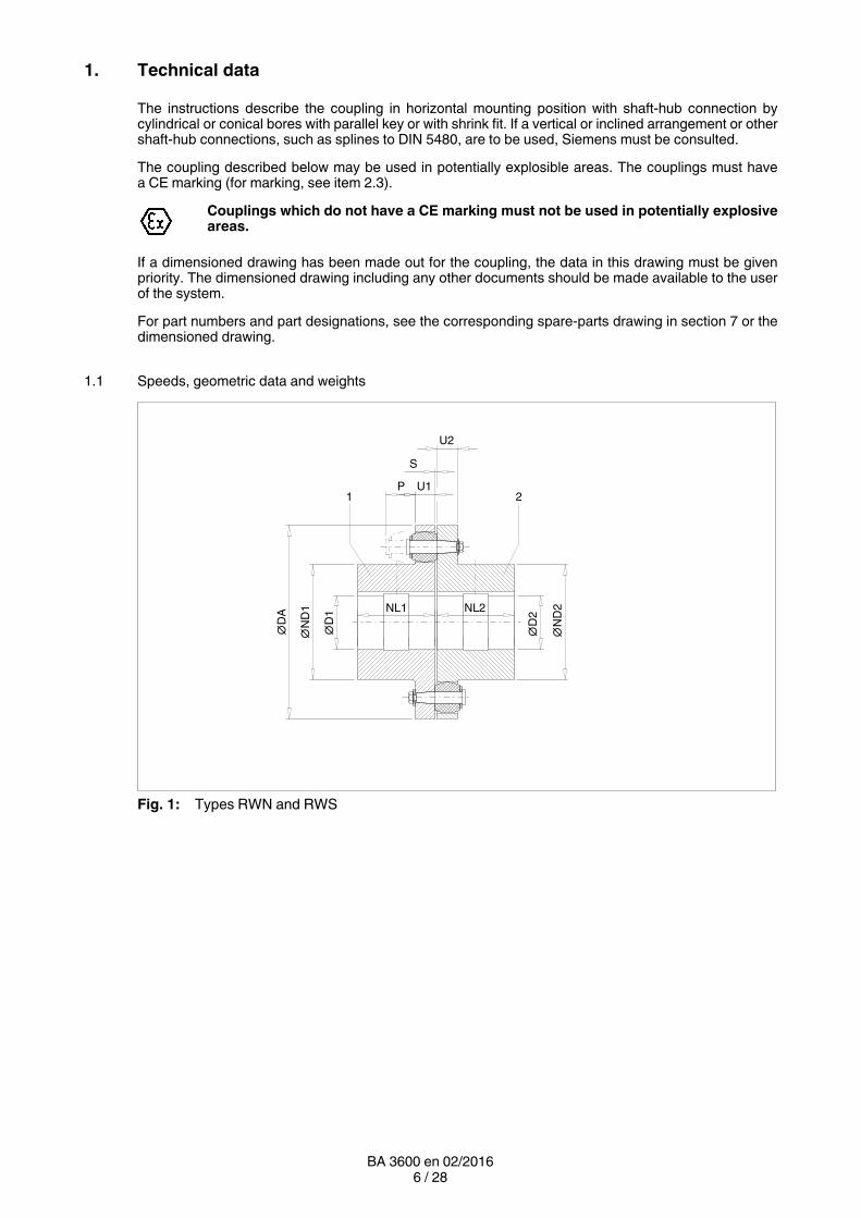
1.1 Speeds, geometric data and weights
U2
∅D
1
S
P U1
∅N
D1
∅D
A
∅D
2
∅N
D2NL1 NL2
1 2
Fig. 1: Types RWN and RWS
7 / 28BA 3600 en 02/2016
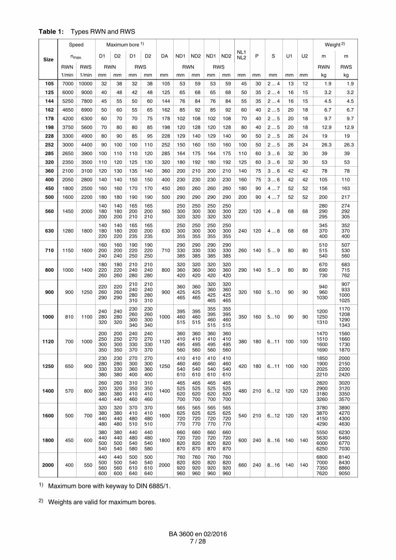
Table 1: Types RWN and RWS
Size
Speed Maximum bore 1)
NL1NL2
Weight 2)
nmax. D1 D2 D1 D2 DA ND1 ND2 ND1 ND2 P S U1 U2 m m
RWN RWS RWN RWS RWN RWS RWN RWS
1/min 1/min mm mm mm mm mm mm mm mm mm mm mm mm mm mm kg kg
105 7000 10000 32 38 32 38 105 53 59 53 59 45 30 2 ... 4 13 12 1.9 1.9
125 6000 9000 40 48 42 48 125 65 68 65 68 50 35 2 ... 4 16 15 3.2 3.2
144 5250 7800 45 55 50 60 144 76 84 76 84 55 35 2 ... 4 16 15 4.5 4.5
162 4650 6900 50 60 55 65 162 85 92 85 92 60 40 2 ... 5 20 18 6.7 6.7
178 4200 6300 60 70 70 75 178 102 108 102 108 70 40 2 ... 5 20 18 9.7 9.7
198 3750 5600 70 80 80 85 198 120 128 120 128 80 40 2 ... 5 20 18 12.9 12.9
228 3300 4900 80 90 85 95 228 129 140 129 140 90 50 2 ... 5 26 24 19 19
252 3000 4400 90 100 100 110 252 150 160 150 160 100 50 2 ... 5 26 24 26.3 26.3
285 2650 3900 100 110 110 120 285 164 175 164 175 110 60 3 ... 6 32 30 39 39
320 2350 3500 110 120 125 130 320 180 192 180 192 125 60 3 ... 6 32 30 53 53
360 2100 3100 120 130 135 140 360 200 210 200 210 140 75 3 ... 6 42 42 78 78
400 2050 2800 140 140 150 150 400 230 230 230 230 160 75 3 ... 6 42 42 105 110
450 1800 2500 160 160 170 170 450 260 260 260 260 180 90 4 ... 7 52 52 156 163
500 1600 2200 180 180 190 190 500 290 290 290 290 200 90 4 ... 7 52 52 200 217
560 1450 2000140180200
140180200
165200210
165200210
560250300320
250300320
250300320
250300320
220 120 4 ... 8 68 68280290295
274292305
630 1280 1800140180220
140180220
165200235
165200235
630250300355
250300355
250300355
250300355
240 120 4 ... 8 68 68345370400
352370400
710 1150 1600160200240
160200240
190220250
190220250
710290330385
290330385
290330385
290330385
260 140 5 ... 9 80 80510515540
507530560
800 1000 1400180220260
180220260
210240280
210240280
800320360420
320360420
320360420
320360420
290 140 5 ... 9 80 80670690730
683715762
900 900 1250220260290
220260290
210240280310
210240280310
900360425465
360425465
320360425465
320360425465
320 160 5...10 90 90940960
1030
907933
10001025
1000 810 1100240280320
240280320
230260300340
230260300340
1000395460515
395460515
355395460515
355395460515
350 160 5...10 90 90120012501310
1170120812901343
1120 700 1000
200250300350
200250300350
240270330370
240270330370
1120
360410495560
360410495560
360410495560
360410495560
380 180 6...11 100 100
1470151016001690
1560166017301870
1250 650 900
230280330380
230280330380
270300360400
270300360400
1250
410460540610
410460540610
410460540610
410460540610
420 180 6...11 100 100
1850190020252210
2000215022002420
1400 570 800
260320380440
260320380440
310350410460
310350410460
1400
465525620700
465525620700
465525620700
465525620700
480 210 6...12 120 120
2820290031803260
3020312033503570
1600 500 700
320380440480
320380440480
370410480510
370410480510
1600
565625720770
565625720770
565625720770
565625720770
540 210 6...12 120 120
3780387041504290
3890427043004630
1800 450 600
380440500540
380440500540
440480540580
440480540580
1800
660720820870
660720820870
660720820870
660720820870
600 240 8...16 140 140
5550563060006250
6230646067707030
2000 400 550
440500560600
440500560600
500540610640
500540610640
2000
760820920960
760820920960
760820920960
760820920960
660 240 8...16 140 140
6800700073507620
8140843088609050
1) Maximum bore with keyway to DIN 6885/1.
2) Weights are valid for maximum bores.
8 / 28BA 3600 en 02/2016
∅D
1
S
P U1
∅N
D1
∅D
A
∅D
2
∅N
D2
NL1 ∅D
B
BB
NL2
1 3
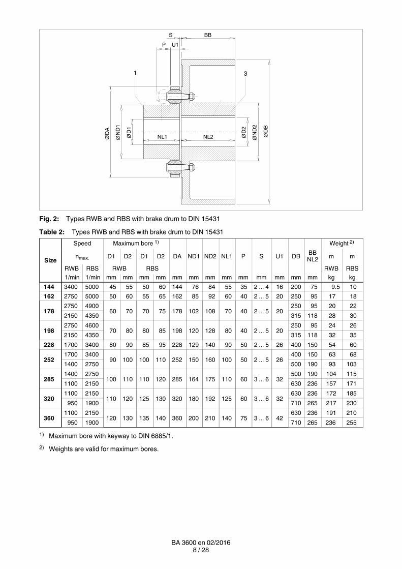
Fig. 2: Types RWB and RBS with brake drum to DIN 15431
Table 2: Types RWB and RBS with brake drum to DIN 15431
Size
Speed Maximum bore 1) Weight 2)
nmax. D1 D2 D1 D2 DA ND1 ND2 NL1 P S U1 DBBB
NL2 m m
RWB RBS RWB RBS RWB RBS
1/min 1/min mm mm mm mm mm mm mm mm mm mm mm mm mm kg kg
144 3400 5000 45 55 50 60 144 76 84 55 35 2 ... 4 16 200 75 9.5 10
162 2750 5000 50 60 55 65 162 85 92 60 40 2 ... 5 20 250 95 17 18
1782750 4900
60 70 70 75 178 102 108 70 40 2 ... 5 20250 95 20 22
2150 4350 315 118 28 30
1982750 4600
70 80 80 85 198 120 128 80 40 2 ... 5 20250 95 24 26
2150 4350 315 118 32 35
228 1700 3400 80 90 85 95 228 129 140 90 50 2 ... 5 26 400 150 54 60
2521700 3400
90 100 100 110 252 150 160 100 50 2 ... 5 26400 150 63 68
1400 2750 500 190 93 103
2851400 2750
100 110 110 120 285 164 175 110 60 3 ... 6 32500 190 104 115
1100 2150 630 236 157 171
3201100 2150
110 120 125 130 320 180 192 125 60 3 ... 6 32630 236 172 185
950 1900 710 265 217 230
3601100 2150
120 130 135 140 360 200 210 140 75 3 ... 6 42630 236 191 210
950 1900 710 265 236 255
1) Maximum bore with keyway to DIN 6885/1.
2) Weights are valid for maximum bores.
9 / 28BA 3600 en 02/2016
∅D
1
ZF x ∅DFB
P U1
∅N
D1
∅D
A NL1
FB
20
B
L1
S
∅D
FN
∅D
FK
∅D
FA
1
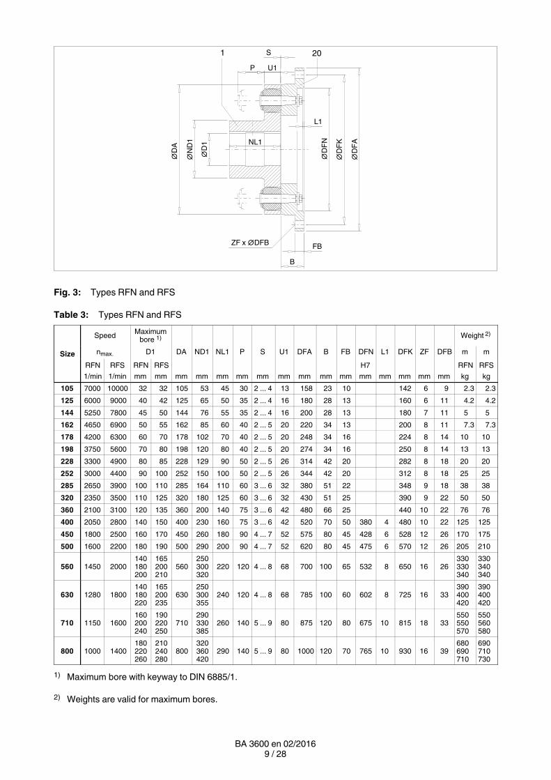
Fig. 3: Types RFN and RFS
Table 3: Types RFN and RFS
Size
SpeedMaximum
bore 1) Weight 2)
nmax. D1 DA ND1 NL1 P S U1 DFA B FB DFN L1 DFK ZF DFB m m
RFN RFS RFN RFS H7 RFN RFS
1/min 1/min mm mm mm mm mm mm mm mm mm mm mm mm mm mm mm mm kg kg
105 7000 10000 32 32 105 53 45 30 2 ... 4 13 158 23 10 142 6 9 2.3 2.3
125 6000 9000 40 42 125 65 50 35 2 ... 4 16 180 28 13 160 6 11 4.2 4.2
144 5250 7800 45 50 144 76 55 35 2 ... 4 16 200 28 13 180 7 11 5 5
162 4650 6900 50 55 162 85 60 40 2 ... 5 20 220 34 13 200 8 11 7.3 7.3
178 4200 6300 60 70 178 102 70 40 2 ... 5 20 248 34 16 224 8 14 10 10
198 3750 5600 70 80 198 120 80 40 2 ... 5 20 274 34 16 250 8 14 13 13
228 3300 4900 80 85 228 129 90 50 2 ... 5 26 314 42 20 282 8 18 20 20
252 3000 4400 90 100 252 150 100 50 2 ... 5 26 344 42 20 312 8 18 25 25
285 2650 3900 100 110 285 164 110 60 3 ... 6 32 380 51 22 348 9 18 38 38
320 2350 3500 110 125 320 180 125 60 3 ... 6 32 430 51 25 390 9 22 50 50
360 2100 3100 120 135 360 200 140 75 3 ... 6 42 480 66 25 440 10 22 76 76
400 2050 2800 140 150 400 230 160 75 3 ... 6 42 520 70 50 380 4 480 10 22 125 125
450 1800 2500 160 170 450 260 180 90 4 ... 7 52 575 80 45 428 6 528 12 26 170 175
500 1600 2200 180 190 500 290 200 90 4 ... 7 52 620 80 45 475 6 570 12 26 205 210
560 1450 2000140180200
165200210
560250300320
220 120 4 ... 8 68 700 100 65 532 8 650 16 26330330340
330340340
630 1280 1800140180220
165200235
630250300355
240 120 4 ... 8 68 785 100 60 602 8 725 16 33390400420
390400420
710 1150 1600160200240
190220250
710290330385
260 140 5 ... 9 80 875 120 80 675 10 815 18 33550550570
550560580
800 1000 1400180220260
210240280
800320360420
290 140 5 ... 9 80 1000 120 70 765 10 930 16 39680690710
690710730
1) Maximum bore with keyway to DIN 6885/1.
2) Weights are valid for maximum bores.
10 / 28BA 3600 en 02/2016
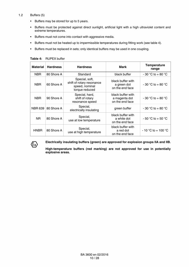
1.2 Buffers (5)
• Buffers may be stored for up to 5 years.
• Buffers must be protected against direct sunlight, artificial light with a high ultraviolet content andextreme temperatures.
• Buffers must not come into contact with aggressive media.
• Buffers must not be heated up to impermissible temperatures during fitting work (see table 4).
• Buffers must be replaced in sets; only identical buffers may be used in one coupling.
Table 4: RUPEX buffer
Material Hardness Hardness MarkTemperature
range
NBR 80 Shore A Standard black buffer - 30 °C to + 80 °C
NBR 60 Shore A
Special, soft,shift of rotary resonance
speed, nominaltorque reduced
black buffer witha green dot
on the end face- 30 °C to + 80 °C
NBR 90 Shore ASpecial, hard,shift of rotary
resonance speed
black buffer witha magenta doton the end face
- 30 °C to + 80 °C
NBR 639 80 Shore ASpecial,
electrically insulatinggreen buffer - 30 °C to + 80 °C
NR 80 Shore ASpecial,
use at low temperature
black buffer witha white dot
on the end face- 50 °C to + 50 °C
HNBR 80 Shore ASpecial,
use at high temperature
black buffer witha red dot
on the end face- 10 °C to + 100 °C
Electrically insulating buffers (green) are approved for explosion groups IIA and IIB.
Hightemperature buffers (red marking) are not approved for use in potentiallyexplosive areas.
11 / 28BA 3600 en 02/2016
2. Notes
2.1 Safety instructions and general notes
All persons involved in the installation, operation, maintenance and repair of thecoupling or clutch must have read and understood these instructions and mustcomply with them at all times. Disregarding these instructions may cause damage tothe product and material and/or injury to persons. Damage caused by disregard ofthese instructions will result in exclusion of liability.
During transport, installation, dismantling, operation and maintenance of the unit, the relevant safety andenvironmental regulations must be complied with at all times.
Lifting gears and load equipment for handling the components must be suitable for theweight of the coupling.
Depending on national regulations, coupling and clutch components may have to be disposed ofseparately or separated for recycling.
The coupling must be stored in a dry environment. Adequate preservation must be carried out.
Operators and users must not make any changes to the coupling themselves over and above the treatmentspecified in these instructions.
If there is any visible damage the coupling or clutch must not be fitted or put intooperation!
The coupling must not be operated unless housed in a suitable enclosure in accordance with the standardsapplying. This also applies to test runs and when checking the direction of rotation.
All work on the coupling must be carried out only when it is at a standstill. Secure the drive unit to preventunintentional switchon! A notice should be attached to the ON switch stating clearly that work is inprogress.
In addition to any generally prescribed personal safety equipment (such as safety shoes, safety clothing,helmet) suitable safety gloves and suitable safety glasses must be worn when handling the couplingor clutch!
Only spare parts made by the manufacturer Siemens must be used.
Any enquiries should be addressed to:
Siemens AGSchlavenhorst 10046395 Bocholt
Tel.: +49 (0)2871 / 92-0Fax: +49 (0)2871 / 92-2596
12 / 28BA 3600 en 02/2016
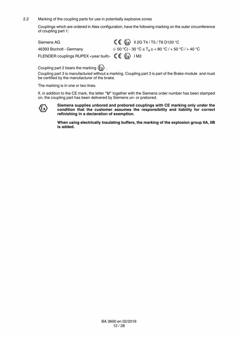
2.2 Marking of the coupling parts for use in potentially explosive zones
Couplings which are ordered in Atex configuration, have the following marking on the outer circumferenceof coupling part 1:
Siemens AG II 2G T4 / T5 / T6 D120 °C
46393 Bocholt ‐ Germany (- 50 °C) - 30 °C ≤ Ta ≤ + 80 °C / + 50 °C / + 40 °C
FLENDER couplings RUPEX <year built> I M2
Coupling part 2 bears the marking .
Coupling part 3 is manufactured without a marking. Coupling part 3 is part of the Brake module and mustbe certified by the manufacturer of the brake.
The marking is in one or two lines.
If, in addition to the CE mark, the letter "U" together with the Siemens order number has been stampedon, the coupling part has been delivered by Siemens un or prebored.
Siemens supplies unbored and prebored couplings with CE marking only under thecondition that the customer assumes the responsibility and liability for correctrefinishing in a declaration of exemption.
When using electrically insulating buffers, the marking of the explosion group IIA, IIBis added.
13 / 28BA 3600 en 02/2016
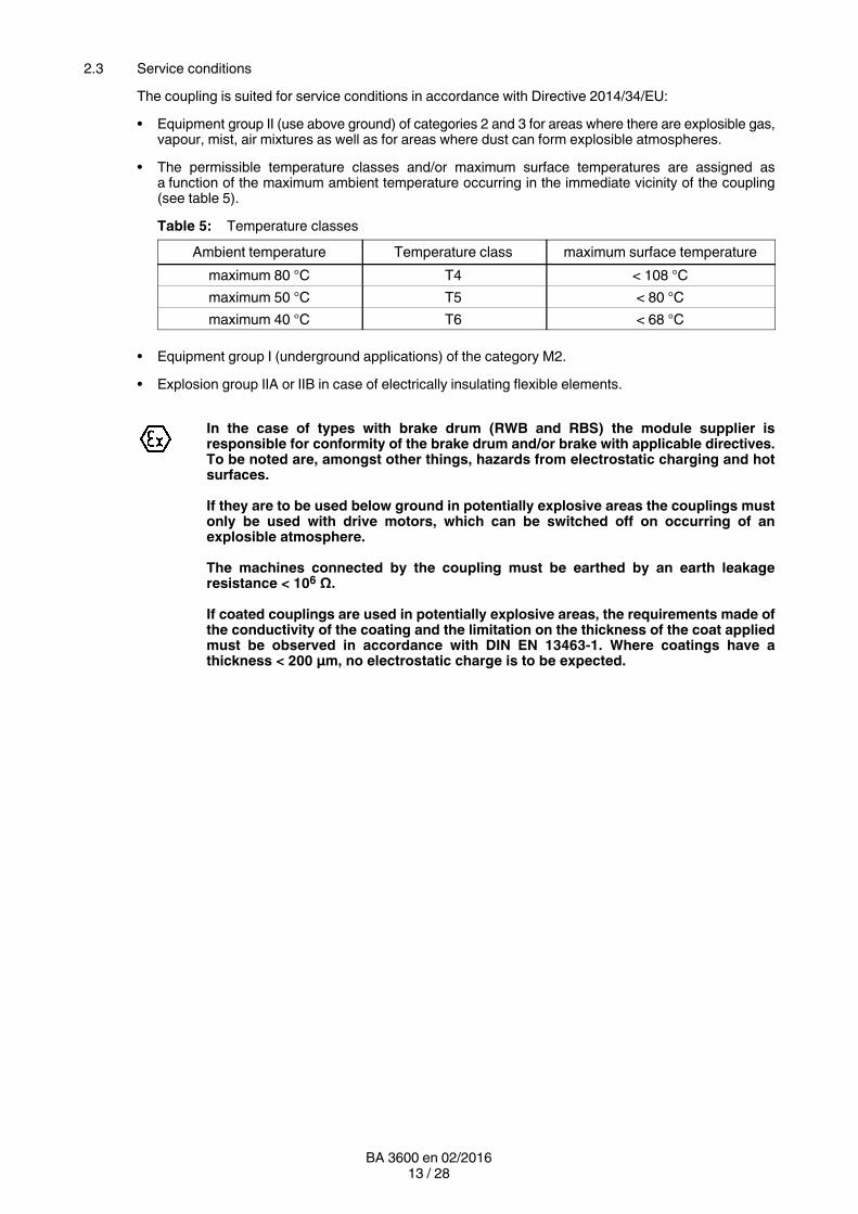
2.3 Service conditions
The coupling is suited for service conditions in accordance with Directive 2014/34/EU:
• Equipment group II (use above ground) of categories 2 and 3 for areas where there are explosible gas,vapour, mist, air mixtures as well as for areas where dust can form explosible atmospheres.
• The permissible temperature classes and/or maximum surface temperatures are assigned asa function of the maximum ambient temperature occurring in the immediate vicinity of the coupling(see table 5).
Table 5: Temperature classes
Ambient temperature Temperature class maximum surface temperature
maximum 80 °C T4 < 108 °C
maximum 50 °C T5 < 80 °C
maximum 40 °C T6 < 68 °C
• Equipment group I (underground applications) of the category M2.
• Explosion group IIA or IIB in case of electrically insulating flexible elements.
In the case of types with brake drum (RWB and RBS) the module supplier isresponsible for conformity of the brake drum and/or brake with applicable directives.To be noted are, amongst other things, hazards from electrostatic charging and hotsurfaces.
If they are to be used below ground in potentially explosive areas the couplings mustonly be used with drive motors, which can be switched off on occurring of anexplosible atmosphere.
The machines connected by the coupling must be earthed by an earth leakageresistance < 106 Ω.
If coated couplings are used in potentially explosive areas, the requirements made ofthe conductivity of the coating and the limitation on the thickness of the coat appliedmust be observed in accordance with DIN EN 134631. Where coatings have athickness < 200 μm, no electrostatic charge is to be expected.
14 / 28BA 3600 en 02/2016
3. Fitting
Coupling parts set up for removal by oilhydraulic shrinkingoff are delivered in a finishmachined stateaccording to the order,
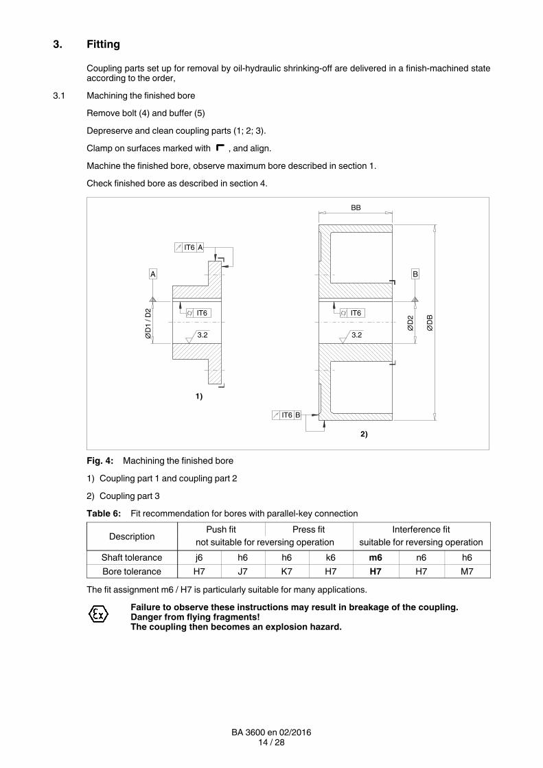
3.1 Machining the finished bore
Remove bolt (4) and buffer (5)
Depreserve and clean coupling parts (1; 2; 3).
Clamp on surfaces marked with , and align.
Machine the finished bore, observe maximum bore described in section 1.
Check finished bore as described in section 4.
BB
A
IT6
∅D
1 /
D2
∅D
2
∅D
B
A
IT6 B
IT6IT6
3.2 3.2
B
2)
1)
Fig. 4: Machining the finished bore
1) Coupling part 1 and coupling part 2
2) Coupling part 3
Table 6: Fit recommendation for bores with parallelkey connection
DescriptionPush fit Press fit Interference fit
not suitable for reversing operation suitable for reversing operation
Shaft tolerance j6 h6 h6 k6 m6 n6 h6
Bore tolerance H7 J7 K7 H7 H7 H7 M7
The fit assignment m6 / H7 is particularly suitable for many applications.
Failure to observe these instructions may result in breakage of the coupling.Danger from flying fragments!The coupling then becomes an explosion hazard.
15 / 28BA 3600 en 02/2016
3.2 Machining the parallel keyway
Arrangement of the parallel keyway centrally between buffer bores or bolt bores.
• Parallel keyway to DIN 6885/1 ISO JS9 with usual operating conditions.
• Width of parallel keyway ISO P9 with reversing operation.
• Width of parallel keyway ISO P9 with coupling part (3).
3.3 Axial fastening
Arrange set screw on the parallel keyway. Only in case of sizes 105 and 125 place the set screw offset 180°to the parallel keyway.
Position of the set screw approximately in the middle of the hub, on coupling part 3 under angle of 25°(see figure 8).
Use threaded studs to DIN 916 with cup points as set screws (setscrew size to table 7).
The set screw should fill out the screw thread as much as possible and must not project beyond the hub.
Alternatively use end plate; as regards recess contact Siemens.
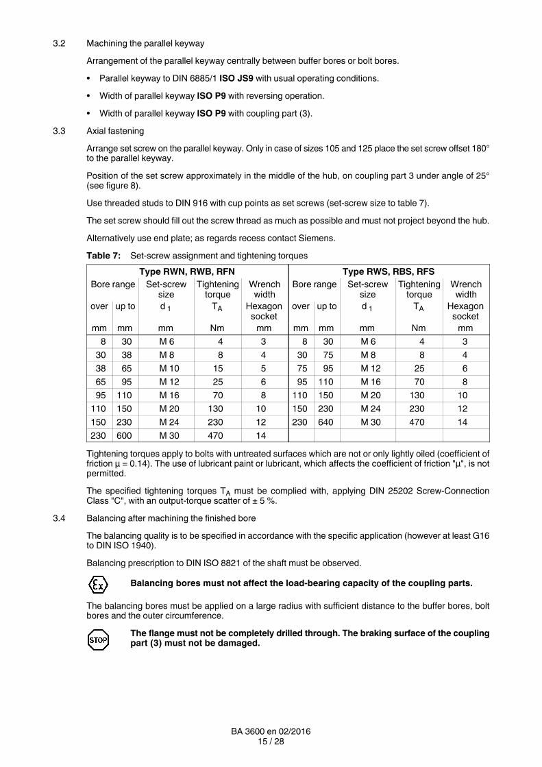
Table 7: Setscrew assignment and tightening torques
Type RWN, RWB, RFN Type RWS, RBS, RFS
Bore range Set-screwsize
Tighteningtorque
Wrenchwidth
Bore range Set-screwsize
Tighteningtorque
Wrenchwidth
over up to d 1 TA Hexagonsocket
over up to d 1 TA Hexagonsocket
mm mm mm Nm mm mm mm mm Nm mm
8 30 M 6 4 3 8 30 M 6 4 3
30 38 M 8 8 4 30 75 M 8 8 4
38 65 M 10 15 5 75 95 M 12 25 6
65 95 M 12 25 6 95 110 M 16 70 8
95 110 M 16 70 8 110 150 M 20 130 10
110 150 M 20 130 10 150 230 M 24 230 12
150 230 M 24 230 12 230 640 M 30 470 14
230 600 M 30 470 14
Tightening torques apply to bolts with untreated surfaces which are not or only lightly oiled (coefficient offriction μ = 0.14). The use of lubricant paint or lubricant, which affects the coefficient of friction "μ", is notpermitted.
The specified tightening torques TA must be complied with, applying DIN 25202 ScrewConnectionClass "C", with an outputtorque scatter of ± 5 %.
3.4 Balancing after machining the finished bore
The balancing quality is to be specified in accordance with the specific application (however at least G16to DIN ISO 1940).
Balancing prescription to DIN ISO 8821 of the shaft must be observed.
Balancing bores must not affect the loadbearing capacity of the coupling parts.
The balancing bores must be applied on a large radius with sufficient distance to the buffer bores, boltbores and the outer circumference.
The flange must not be completely drilled through. The braking surface of the couplingpart (3) must not be damaged.
16 / 28BA 3600 en 02/2016
3.5 Placing the coupling parts with cylindrical and conical bore with parallel key
Unscrew the set screw.
Clean the holes and shaft ends.
Coat the bores of the coupling parts (1; 2; 3) and the shafts with MoS2 mounting paste (e.g. MicrogleitLP 405).
Coupling parts (1; 2; 3) with tapered bore and parallelkey connection must be fittedin cold condition and secured with suitable end plates, without drawing the couplingparts (1; 2; 3) further onto the taper (fitting dimension = 0).
Place the coupling parts (1; 2; 3); in case of cylindrical bore, heat up to max. + 150 °C, if necessary. Whenheating up observe the temperature range of the buffers (5) (see table 5); if necessary demount the buffers(5).
Heated coupling parts form an explosion hazard, therefor there must not be anexplosible atmosphere when fitting the coupling parts.
Axial securing is effected by means of the set screw or end plate. When securing by set screw the shaftmust not project or be set back from the inner sides of the hub.
Fit the set screw or end plate (tightening torques of the set screw to table 7).
Failure to observe these instructions may result in breakage of the coupling.Danger from flying fragments!The coupling then becomes an explosion hazard.
3.6 Fitting of coupling parts in case of a cylindrical and tapered interference fit set up for removal byoilhydraulic shrinkingoff
The information specified on the dimensioned drawing should be observed withpriority.
Unscrew screw plugs (101 / 201 / 301) from the coupling parts (1; 2; 3). Clean and dry holes and shaft ends.The oil channels and oilcirculation grooves must also be free from dirt.
The machine shaft and the bore of the coupling part (1; 2; 3) must be absolutely cleanand free of grease and oil!
Demount buffers (5).
Protect seals for the input and output side against damage and heating to over + 80 °C.(Use heat shields to protect against radiant heat.)
The coupling parts (1; 2; 3) must be fitted in hot condition and, depending on the shrink dimension, heatedto the temperature indicated on the dimensioned drawing.
Heating may be done inductively, in a stove or with a burner.
Burner an heated coupling parts form an explosion hazard, therefor there must not bean explosible atmosphere when fitting the coupling parts.
Before fitting, the bore size of the heated coupling parts (1; 2; 3) must be checked, e.g. with a boreholegauge.
The coupling parts (1; 2; 3) should be pushed smartly onto the shaft up to the position specified in thedimensioned drawing.
The coupling parts (1; 2; 3) must be held in position on the shaft with the aid ofa suitable retaining device, until they cool down and seat firmly.
In case of tapered interference fit and non selflocking connection, the axial securing takes place by an endplate.
After the coupling parts (1; 2; 3) have cooled down to ambient temperature the oil channels must be filledwith clean forcing oil, e.g. ISO VG 150, and resealed with the screw plugs (101 / 201 / 301)(rust protection).
17 / 28BA 3600 en 02/2016
3.7 Fitting the coupling
In the case of types RFN and RFS, bolt the coupling part 20 (20) to the counterpart (tightening torques inaccordance with table 10).
If necessary, fit buffer (5) and bolt (4). Observe the temperature range (see table 4).
Bolt and tapered bore must be absolutely clean and free of grease!
Compose balancing groups in accordance with the marking.
Tighten hexagon nuts (7) or bolts (11) using a torque wrench (tightening torques in accordance withtable 9) and secure them with threadlocking medium "mediumfirm" (e.g. Loctite 243). Apply just a smallquantity of Loctite to the bolt (11), otherwise there is a risk that the Loctite may seal the transverse bore.
Align the coupling as described in item 3.8.
3.8 Possible misalignments
Smin.
Smax.
Smin.
Smax.
1) 3)2)
ΔKa
ΔK
w
ΔK
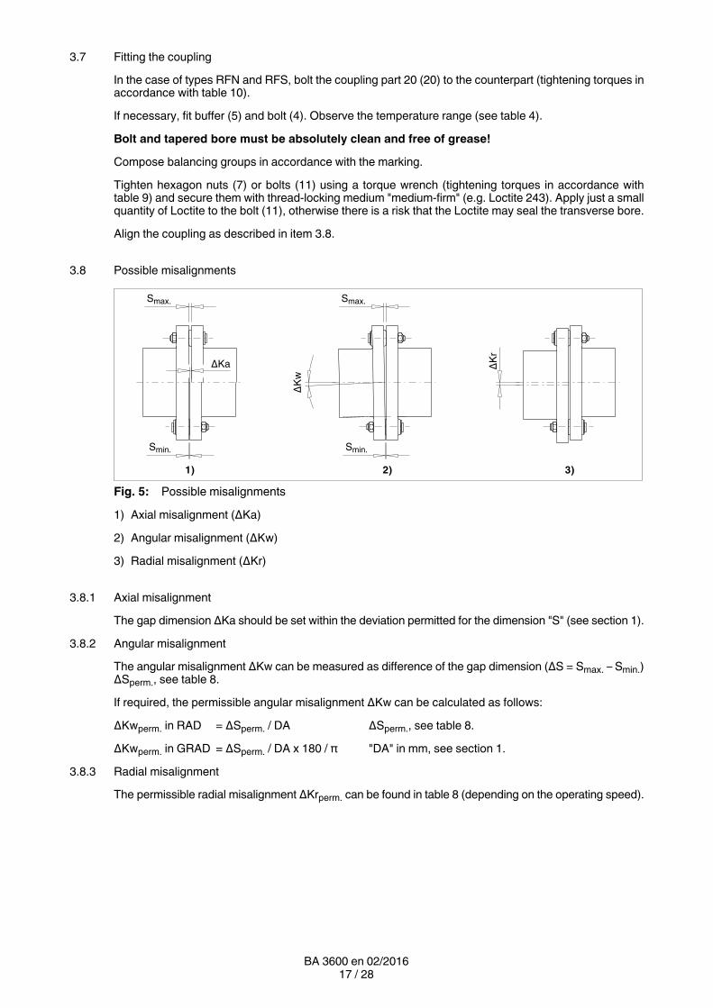
rFig. 5: Possible misalignments
1) Axial misalignment (ΔKa)
2) Angular misalignment (ΔKw)
3) Radial misalignment (ΔKr)
3.8.1 Axial misalignment
The gap dimension ΔKa should be set within the deviation permitted for the dimension "S" (see section 1).
3.8.2 Angular misalignment
The angular misalignment ΔKw can be measured as difference of the gap dimension (ΔS = Smax. – Smin.)ΔSperm., see table 8.
If required, the permissible angular misalignment ΔKw can be calculated as follows:
ΔKwperm. in RAD = ΔSperm. / DA ΔSperm., see table 8.
ΔKwperm. in GRAD = ΔSperm. / DA x 180 / π "DA" in mm, see section 1.
3.8.3 Radial misalignment
The permissible radial misalignment ΔKrperm. can be found in table 8 (depending on the operating speed).
18 / 28BA 3600 en 02/2016
3.9 Alignment
When aligning, the angular and radial misalignment should be kept as low as possible.
Misalignment values specified in table 8 are maximum permissible overall values in operation, resultingfrom mispositioning through imprecision during alignment and misalignment through operation(e.g. deformation through load, heat expansion).
Reduced misalignment in the coupling minimises expected wear on the flexible elements. Misalignmentin the coupling gives rise to restorative forces which may impose inadmissible stress on adjacent machineparts (e.g. bearings).
3.10 Shaftmisalignment values during operation
The following maximum permissible misalignments must by no means be exceeded duringoperation.When aligning the angular and radial misalignment should be kept appreciably smaller(tending towards zero).
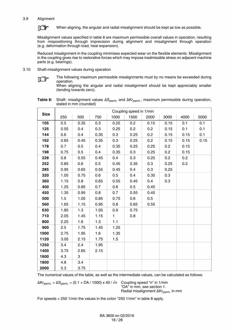
Table 8: Shaft misalignment values ΔSperm. and ΔKrperm., maximum permissible during operation,stated in mm (rounded)
SizeCoupling speed in 1/min
250 500 750 1000 1500 2000 3000 4000 5000
105 0.5 0.35 0.3 0.25 0.2 0.15 0.15 0.1 0.1
125 0.55 0.4 0.3 0.25 0.2 0.2 0.15 0.1 0.1
144 0.6 0.4 0.35 0.3 0.25 0.2 0.15 0.15 0.1
162 0.65 0.45 0.35 0.3 0.25 0.2 0.15 0.15 0.15
178 0.7 0.5 0.4 0.35 0.25 0.25 0.2 0.15
198 0.75 0.5 0.4 0.35 0.3 0.25 0.2 0.15
228 0.8 0.55 0.45 0.4 0.3 0.25 0.2 0.2
252 0.85 0.6 0.5 0.45 0.35 0.3 0.25 0.2
285 0.95 0.65 0.55 0.45 0.4 0.3 0.25
320 1.05 0.75 0.6 0.5 0.4 0.35 0.3
360 1.15 0.8 0.65 0.55 0.45 0.4 0.3
400 1.25 0.85 0.7 0.6 0.5 0.45
450 1.35 0.95 0.8 0.7 0.55 0.45
500 1.5 1.05 0.85 0.75 0.6 0.5
560 1.65 1.15 0.95 0.8 0.65 0.55
630 1.85 1.3 1.05 0.9 0.75
710 2.05 1.45 1.15 1 0.8
800 2.25 1.6 1.3 1.1
900 2.5 1.75 1.45 1.25
1000 2.75 1.95 1.6 1.35
1120 3.05 2.15 1.75 1.5
1250 3.4 2.4 1.95
1400 3.75 2.65 2.15
1600 4.3 3
1800 4.8 3.4
2000 5.3 3.75
The numerical values of the table, as well as the intermediate values, can be calculated as follows:
ΔKrperm. = ΔSperm. = (0.1 + DA / 1000) x 40 / √n Coupling speed "n" in 1/min"DA" in mm, see section 1.Radial misalignment ΔKrperm. in mm
For speeds < 250 1/min the values in the colon "250 1/min" in table 8 apply.
19 / 28BA 3600 en 02/2016
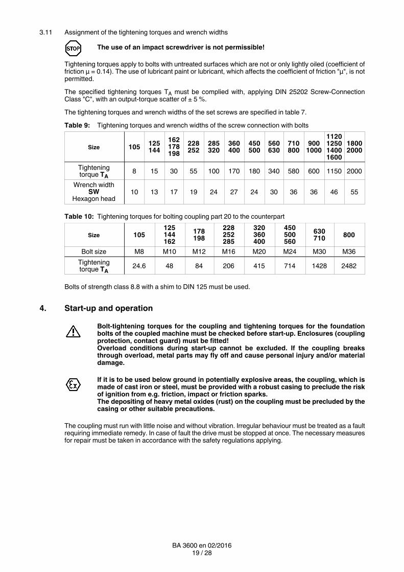
3.11 Assignment of the tightening torques and wrench widths
The use of an impact screwdriver is not permissible!
Tightening torques apply to bolts with untreated surfaces which are not or only lightly oiled (coefficient offriction μ = 0.14). The use of lubricant paint or lubricant, which affects the coefficient of friction "μ", is notpermitted.
The specified tightening torques TA must be complied with, applying DIN 25202 ScrewConnectionClass "C", with an outputtorque scatter of ± 5 %.
The tightening torques and wrench widths of the set screws are specified in table 7.
Table 9: Tightening torques and wrench widths of the screw connection with bolts
Size 105125144
162178198
228252
285320
360400
450500
560630
710800
9001000
1120125014001600
18002000
Tighteningtorque TA
8 15 30 55 100 170 180 340 580 600 1150 2000
Wrench widthSW
Hexagon head10 13 17 19 24 27 24 30 36 36 46 55
Table 10: Tightening torques for bolting coupling part 20 to the counterpart
Size 105125144162
178198
228252285
320360400
450500560
630710
800
Bolt size M8 M10 M12 M16 M20 M24 M30 M36
Tighteningtorque TA
24.6 48 84 206 415 714 1428 2482
Bolts of strength class 8.8 with a shim to DIN 125 must be used.
4. Startup and operation
Bolttightening torques for the coupling and tightening torques for the foundationbolts of the coupled machine must be checked before startup. Enclosures (couplingprotection, contact guard) must be fitted!Overload conditions during startup cannot be excluded. If the coupling breaksthrough overload, metal parts may fly off and cause personal injury and/or materialdamage.
If it is to be used below ground in potentially explosive areas, the coupling, which ismade of cast iron or steel, must be provided with a robust casing to preclude the riskof ignition from e.g. friction, impact or friction sparks.The depositing of heavy metal oxides (rust) on the coupling must be precluded by thecasing or other suitable precautions.
The coupling must run with little noise and without vibration. Irregular behaviour must be treated as a faultrequiring immediate remedy. In case of fault the drive must be stopped at once. The necessary measuresfor repair must be taken in accordance with the safety regulations applying.
20 / 28BA 3600 en 02/2016
5. Faults, causes and remedy
5.1 Possible cause of fault
Change in alignment:
─ Rectify the cause of the change in alignment (e.g. loose foundation bolts).
─ Align the coupling.
─ Check the axial fastening and, if necessary, adjust.
─ Wear check, procedure as described in section 6.
Buffers (5) worn:
─ Check wear of the buffers (5) as described in section 6; if necessary replace the buffers (5).
5.2 Incorrect use
Failure to observe these instructions may result in breakage of the coupling.Danger from flying fragments!Through incorrect use the coupling may become an explosion hazard.
5.2.1 Frequent faults when selecting the coupling and/or coupling size
• Important information for describing the drive and the environment are not communicated.
• System torque too high.
• System speed too high.
• Application factor not correctly selected.
• Chemically aggressive environment not taken into consideration.
• The ambient temperature is not permissible.
• Finished bore with inadmissible diameter and/or inadmissible assigned fits.
• Machining of parallel keyways of which the width across corners is greater than the width acrosscorners of the parallel keyways to DIN 6885/1 with a maximum permissible bore.
• The transmission capacity of the shafthub connection is not appropriate to the operating conditions.
• Maximum load or overload conditions are not being taken into consideration.
• Dynamic load conditions are not being taken into consideration.
• Shafthub connection resulting in impermissible material stress on the coupling.
• Operating conditions are being changed without authorisation.
• Coupling and machine / drive train form a critical torsional, axial and bending vibration system.
• Fatigue torque load too high.
21 / 28BA 3600 en 02/2016
5.2.2 Frequent faults when fitting the coupling
• Components with transport or other damage are being fitted.
• When fitting coupling parts in a heated condition, already fitted RUPEX buffers (5) are beingexcessively heated.
• The shaft diameter is beyond the specified tolerance range.
• Coupling parts are being interchanged, i.e. their assignment to the specified shaft is incorrect.
• Specified axial fastenings are not fitted.
• Specified tightening torques are not being adhered to.
• Bolts are inserted dry or greased.
• Flange surfaces of screwed connections have not been cleaned.
• Alignment / shaftmisalignment values do not match those in the instructions manual.
• The coupled machines are not correctly fastened to the foundation, and as a result shifting of themachines e.g. through loosening of the foundationscrew connection is causing excessivedisplacement of the coupling parts.
• The coupled machines are not sufficiently earthed.
• RUPEX buffers are not fitted.
• The coupling guard used is not suitable.
5.2.3 Frequent faults in maintenance
• Maintenance intervals are not being adhered to.
• No genuine RUPEX spare parts are being used.
• Old or damaged RUPEX spare parts are being used.
• The fitted buffers (5) are different.
• Leakage in the vicinity of the coupling is not being identified and as a result chemically aggressivemedia are damaging the coupling.
• Fault indications (noise, vibration, etc.) are not being observed.
• Specified tightening torques are not being adhered to.
• Alignment / shaftmisalignment values do not match those in the instructions manual.
22 / 28BA 3600 en 02/2016
6. Maintenance and repair
6.1 Maintenance interval
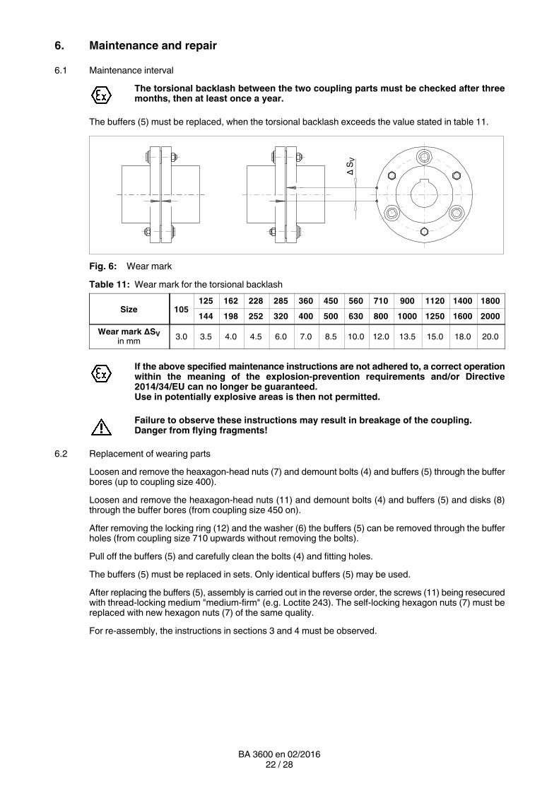
The torsional backlash between the two coupling parts must be checked after threemonths, then at least once a year.
The buffers (5) must be replaced, when the torsional backlash exceeds the value stated in table 11.
Δ S
V
Fig. 6: Wear mark
Table 11: Wear mark for the torsional backlash
Size 105125 162 228 285 360 450 560 710 900 1120 1400 1800
144 198 252 320 400 500 630 800 1000 1250 1600 2000
Wear mark ΔSVin mm
3.0 3.5 4.0 4.5 6.0 7.0 8.5 10.0 12.0 13.5 15.0 18.0 20.0
If the above specified maintenance instructions are not adhered to, a correct operationwithin the meaning of the explosionprevention requirements and/or Directive2014/34/EU can no longer be guaranteed.Use in potentially explosive areas is then not permitted.
Failure to observe these instructions may result in breakage of the coupling.Danger from flying fragments!
6.2 Replacement of wearing parts
Loosen and remove the heaxagonhead nuts (7) and demount bolts (4) and buffers (5) through the bufferbores (up to coupling size 400).
Loosen and remove the heaxagonhead nuts (11) and demount bolts (4) and buffers (5) and disks (8)through the buffer bores (from coupling size 450 on).
After removing the locking ring (12) and the washer (6) the buffers (5) can be removed through the bufferholes (from coupling size 710 upwards without removing the bolts).
Pull off the buffers (5) and carefully clean the bolts (4) and fitting holes.
The buffers (5) must be replaced in sets. Only identical buffers (5) may be used.
After replacing the buffers (5), assembly is carried out in the reverse order, the screws (11) being resecuredwith threadlocking medium "mediumfirm" (e.g. Loctite 243). The selflocking hexagon nuts (7) must bereplaced with new hexagon nuts (7) of the same quality.
For reassembly, the instructions in sections 3 and 4 must be observed.
23 / 28BA 3600 en 02/2016
6.2.1 Extracting the bolts in the case of coupling sizes 450 to 2000 with the demountijg box
For demounting the bolts Siemens offers a hydraulic extracting device, which can be provided on request.
Observe instructions manual BA 3600.1, "Demounting box for extracting RUPEXbolts"!
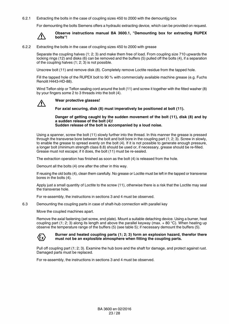
6.2.2 Extracting the bolts in the case of coupling sizes 450 to 2000 with grease
Separate the coupling halves (1; 2; 3) and make them free of load. From coupling size 710 upwards thelocking rings (12) and disks (6) can be removed and the buffers (5) pulled off the bolts (4), if a separationof the coupling halves (1; 2; 3) is not possible.
Unscrew bolt (11) and remove disk (8). Completely remove Loctite residue from the tapped hole.
Fill the tapped hole of the RUPEX bolt to 90 % with commercially available machine grease (e.g. FuchsRenolit H443HD88).
Wind Teflon strip or Teflon sealing cord around the bolt (11) and screw it together with the fitted washer (8)by your fingers some 2 to 3 threads into the bolt (4).
Wear protective glasses!
For axial securing, disk (8) must imperatively be positioned at bolt (11).
Danger of getting caught by the sudden movement of the bolt (11), disk (8) and bya sudden release of the bolt (4)!Sudden release of the bolt is accompanied by a loud noise.
Using a spanner, screw the bolt (11) slowly further into the thread. In this manner the grease is pressedthrough the transverse bore between the bolt and bolt bore in the coupling part (1; 2; 3). Screw in slowly,to enable the grease to spread evenly on the bolt (4). If it is not possible to generate enough pressure,a longer bolt (minimum strength class 8.8) should be used or, if necessary, grease should be refilled.Grease must not escape; if it does, the bolt (11) must be resealed.
The extraction operation has finished as soon as the bolt (4) is released from the hole.
Demount all the bolts (4) one after the other in this way.
If reusing the old bolts (4), clean them carefully. No grease or Loctite must be left in the tapped or transversebores in the bolts (4).
Apply just a small quantity of Loctite to the screw (11), otherwise there is a risk that the Loctite may sealthe transverse hole.
For reassembly, the instructions in sections 3 and 4 must be observed.
6.3 Demounting the coupling parts in case of shafthub connection with parallel key
Move the coupled machines apart.
Remove the axial fastening (set screw, end plate). Mount a suitable detaching device. Using a burner, heatcoupling part (1; 2; 3) along its length and above the parallel keyway (max. + 80 °C). When heating upobserve the temperature range of the buffers (5) (see table 5); if necessary demount the buffers (5).
Burner and heated coupling parts (1; 2; 3) form an explosion hazard, therefor theremust not be an explosible atmosphere when fitting the coupling parts.
Pull off coupling part (1; 2; 3). Examine the hub bore and the shaft for damage, and protect against rust.Damaged parts must be replaced.
For reassembly, the instructions in sections 3 and 4 must be observed.
24 / 28BA 3600 en 02/2016
6.4 Demounting the coupling parts in case of a cylindrical and tapered interference fit set up for removal byoilhydraulic shrinkingoff
Move the coupled machines apart.
Demount buffers (5).
For demounting the following tools are needed:
• For each oil channel (for number, see the dimensioned drawing) an oil pump with pressure gauge(min. 2 500 bar) or a motor pump with corresponding number of independently closable connectionsIn case of coupling parts (1; 2; 3) with stepped bore, a motordriven pump must be connected up to theoil channel located at the point of transition from the smaller bore to the larger, as a large quantity of oilper unit of time is needed here.
• Suitable connections and pipes.
• 1 detaching device or retaining plate with retaining screws or threaded spindles with nuts (material ofscrews and spindles min. 10.9, material of nuts identical to that of the screws).
• 1 hydraulic cylinder with oil pump. Note displacement and pressure of the hydraulic cylinder (for axialforce, consult Siemens or refer to the dimensioned drawing).
Observe manufacturer's instructions for using forcingoff/detaching device andpumps.
Fit the detaching device.
Secure coupling part (1; 2; 3) and detaching device, using suitable lifting equipment!
In case of tapered interference fit, to prevent the coupling part (1; 2; 3) from suddenlycoming off, it must be secured axially.
The screw plugs (101 / 201 / 301) must be removed from the oil channels. One oil pump must be bled andconnected up to middle oil channel.
Then apply the pressure specified on the dimensioned drawing to the pump until oil emerges from theadjacent connections or at the end faces.
The maximum pressure specified on the dimensioned drawing must not be exceeded.
During the entire operation the pressure must be maintained at a constant level on allthe oil channels to which pressure is applied.
Bleed the next oil pump, connect it up to the adjacent oil channel and operate it at the pressure specifiedon the dimensioned drawing, until oil emerges from the adjacent connections or at the end faces.
If, when pressure is applied, oil emerges to the extent that pressure cannot be maintained, a thicker oil mustbe specified.
Only when an unbroken ring of oil emerges from both end faces can pressure be applied to the hydrauliccylinder to slide the coupling part (1; 2; 3) smartly off the shaft.
All the oil must be completely collected and disposed of in accordance with the regulations applying.
Note stroke of hydraulic cylinder. If readjustment is necessary, the end face of thehydraulic cylinder must stop between 2 oil channels.
After detaching, the oil pumps and the detaching device must be removed from the coupling part (1; 2; 3).
Examine the hub bore and the shaft for damage, and protect against rust. Damaged parts must bereplaced.
For reassembly, the instructions in sections 3 and 4 must be observed.
25 / 28BA 3600 en 02/2016
7. Stocking spare parts
7.1 Spare parts
For ordering spare parts state the following data, as far as possible:
• Siemens order number and position
• Drawing number
• Coupling type and coupling size
• Part numer (see spareparts list)
• Bore, bore tolerance, keyway and balancing as well as particular characteristics such asflangeconnection dimensions, intermediateshaft length, brakedrum dimensions.
• Any special details such as temperature, electrically insulating.
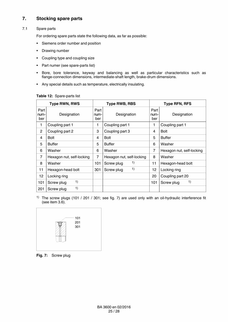
Table 12: Spareparts list
Type RWN, RWS Type RWB, RBS Type RFN, RFS
Partnumber
DesignationPartnumber
DesignationPartnumber
Designation
1 Coupling part 1 1 Coupling part 1 1 Coupling part 1
2 Coupling part 2 3 Coupling part 3 4 Bolt
4 Bolt 4 Bolt 5 Buffer
5 Buffer 5 Buffer 6 Washer
6 Washer 6 Washer 7 Hexagon nut, selflocking
7 Hexagon nut, selflocking 7 Hexagon nut, selflocking 8 Washer
8 Washer 101 Screw plug 1) 11 Hexagonhead bolt
11 Hexagonhead bolt 301 Screw plug 1) 12 Locking ring
12 Locking ring 20 Coupling part 20
101 Screw plug 1) 101 Screw plug 1)
201 Screw plug 1)
1) The screw plugs (101 / 201 / 301; see fig. 7) are used only with an oilhydraulic interference fit(see item 3.6).
101
301
201
Fig. 7: Screw plug
26 / 28BA 3600 en 02/2016
5 114 86125 118645 76
4) 5) 6)
4
21 31 201
1) 2) 3)
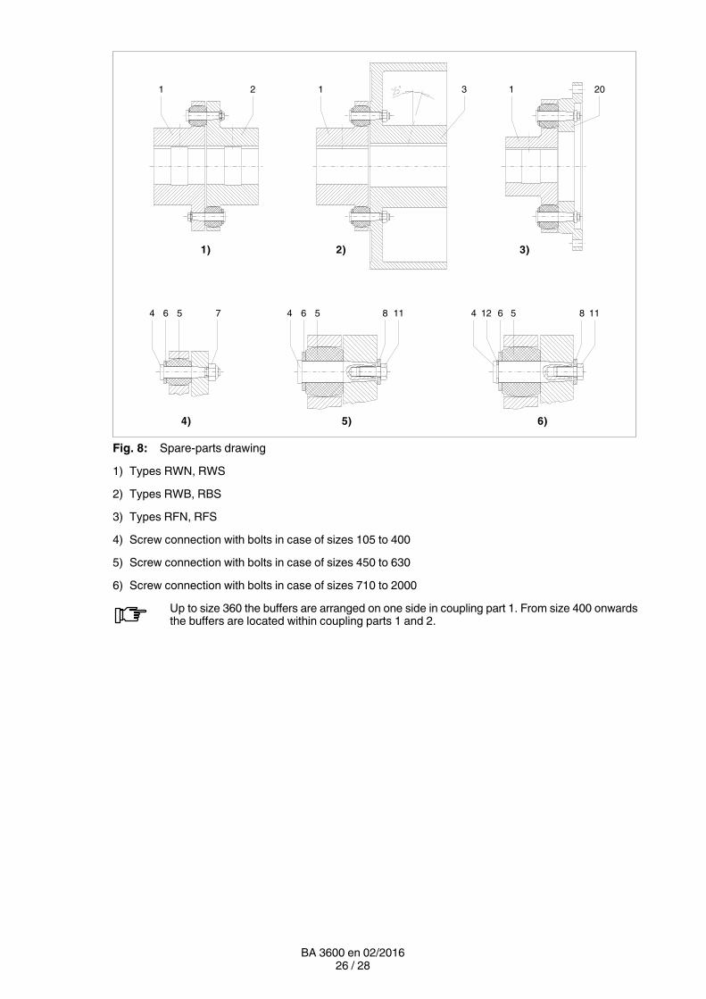
Fig. 8: Spareparts drawing
1) Types RWN, RWS
2) Types RWB, RBS
3) Types RFN, RFS
4) Screw connection with bolts in case of sizes 105 to 400
5) Screw connection with bolts in case of sizes 450 to 630
6) Screw connection with bolts in case of sizes 710 to 2000
Up to size 360 the buffers are arranged on one side in coupling part 1. From size 400 onwardsthe buffers are located within coupling parts 1 and 2.
27 / 28BA 3600 en 02/2016
8. Declarations
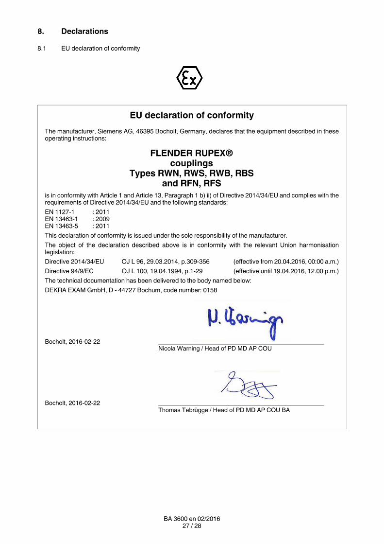
8.1 EU declaration of conformity
EU declaration of conformity
The manufacturer, Siemens AG, 46395 Bocholt, Germany, declares that the equipment described in theseoperating instructions:
FLENDER RUPEX®couplings
Types RWN, RWS, RWB, RBSand RFN, RFS
is in conformity with Article 1 and Article 13, Paragraph 1 b) ii) of Directive 2014/34/EU and complies with therequirements of Directive 2014/34/EU and the following standards:
EN 1127-1 : 2011EN 13463‐1 : 2009EN 13463‐5 : 2011
This declaration of conformity is issued under the sole responsibility of the manufacturer.
The object of the declaration described above is in conformity with the relevant Union harmonisationlegislation:
Directive 2014/34/EU OJ L 96, 29.03.2014, p.309-356 (effective from 20.04.2016, 00:00 a.m.)
Directive 94/9/EC OJ L 100, 19.04.1994, p.1-29 (effective until 19.04.2016, 12.00 p.m.)
The technical documentation has been delivered to the body named below:
DEKRA EXAM GmbH, D - 44727 Bochum, code number: 0158
Bocholt, 2016‐02‐22Nicola Warning / Head of PD MD AP COU
Bocholt, 2016‐02‐22Thomas Tebrügge / Head of PD MD AP COU BA

Siemens AGIndustry SectorMechanical DrivesAlfred-Flender-Straße 7746395 BocholtGERMANY
www.siemens.com/drivetechnologies
Subject to modifications
© Siemens AG 2012
Further Information:
"FLENDER gear units" on the Internetwww.siemens.com/gearunits
"FLENDER couplings" on the Internetwww.siemens.com/couplings
Service & Support:http://support.automation.siemens.com/WW/view/en/10803928/133300
Lubricants:http://support.automation.siemens.com/WW/view/en/42961591/133000