Embed Size (px)
Citation preview

SE
RIE
S 3
0
Pitch 30 mm
Drive system Central
Belt width Multiples of 10 mm
Advised minimum width 150 mm
Rod diameter Ø 4.6 mm
FLAT TOP PERFORATED
FLUSH GRID RAISED RIB
SLIDING ROLLERS
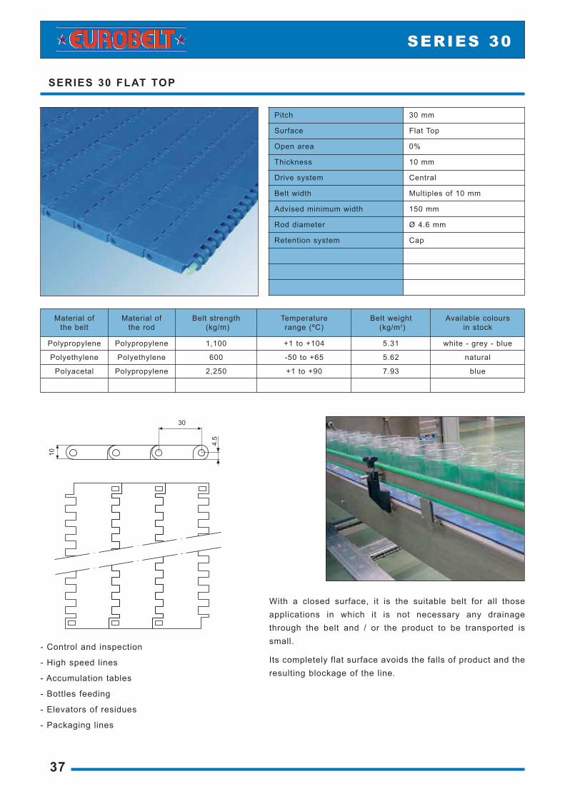
With a closed surface, it is the suitable belt for all thoseapplications in which it is not necessary any drainagethrough the belt and / or the product to be transported issmall.
Its completely flat surface avoids the falls of product and theresulting blockage of the line.
- Control and inspection
- High speed lines
- Accumulation tables
- Bottles feeding
- Elevators of residues
- Packaging lines
SERIES 30 FLAT TOP
37
SERIES 30
Pitch 30 mm
Surface Flat Top
Open area 0%
Thickness 10 mm
Drive system Central
Belt width Multiples of 10 mm
Advised minimum width 150 mm
Rod diameter Ø 4.6 mm
Retention system Cap
Material of the belt
Material of the rod
Belt strength(kg/m)
Temperature range (ºC)
Belt weight(kg/m2)
Available colours in stock
Polypropylene Polypropylene 1,100 +1 to +104 5.31 white - grey - blue
Polyethylene Polyethylene 600 -50 to +65 5.62 natural
Polyacetal Polypropylene 2,250 +1 to +90 7.93 blue

With a 17% open area, it has a completely smooth surfacewith small, straight, and grille-shaped openings withoutstructural obstacles.
This is the suitable belt for applications needing a drainagethrough the belt and in which the product to be transportedis small.
SERIES 30 PERFORATED FLAT TOP
38
INF
O3
1-3
23
02
04
0-4
15
08
09
3D
ATA
A2
4IN
DU
ST
RY
SERIES 30
Pitch 30 mm
Surface Perforated Flat Top
Open area 17%
Thickness 10 mm
Dimensions of openings 2 x 5 mm - 2 x 8 mm
Drive system Central
Belt width Multiples of 10 mm
Advised minimum width 150 mm
Rod diameter Ø 4.6 mm
Retention system Cap
Material of the belt
Material of the rod
Belt strength(kg/m)
Temperature range (ºC)
Belt weight(kg/m2)
Available colours in stock
Polypropylene Polypropylene 1,100 +1 to +104 5.01 white - grey
Polyethylene Polyethylene 600 -50 to +65 5.20 natural
Polyacetal Polypropylene 2,250 +1 to +90 7.33 blue

It has a grille-shaped configuration, with a 41% of open areaand a completely smooth surface.
It is ideal for applications in which it is needed a drainagethrough the belt, avoiding any accumulation of particles onits surface.
The cleaning by applying air or water under pressurethrough the belt is very easy.
- Tyre production lines
- Defreezing
- Washers
- Turning round of boxes
SERIES 30 FLUSH GRID
39
SERIES 30
Pitch 30 mm
Surface Flush Grid
Open area 41%
Thickness 9 mm
Drive system Central
Belt width Multiples of 10 mm
Advised minimum width 150 mm
Rod diameter Ø 4.6 mm
Retention system Cap
Material of the belt
Material of the rod
Belt strength(kg/m)
Temperature range (ºC)
Belt weight(kg/m2)
Available colours in stock
Polypropylene Polypropylene 1,100 +1 to +104 3.71 white - grey
Polyethylene Polyethylene 600 -50 to +65 4.00 natural
Polyacetal Polypropylene 2,250 +1 to +90 5.60 blue

It has been designed to transfer products by means of fingerplates.
Thanks to its even, ribbed surface it is recommended foraccumulation of containers of uncertain stability when it isnecessary the use of finger plates. - Casing
- Coolers
- Palletisers and depalletisers
- Icing of frozen products
- Plastic film wrapping
SERIES 30 RAISED RIB
40
INF
O3
1-3
23
02
04
0-4
15
08
09
3D
ATA
A2
4IN
DU
ST
RY
SERIES 30
Pitch 30 mm
Surface Raised Rib
Open area 41%
Thickness 15 mm
Drive system Central
Belt width Multiples of 10 mm
Advised minimum width 150 mm
Rod diameter Ø 4.6 mm
Retention system Cap
Material of the belt
Material of the rod
Belt strength(kg/m)
Temperature range (ºC)
Belt weight(kg/m2)
Available colours in stock
Polypropylene Polypropylene 1,100 +1 to +104 5.44 grey
Polyacetal Polypropylene 2,250 +1 to +90 8.30 blue

The small rollers inserted on its surface, that revolvewhenever there is accumulation, avoid crushing anddamages in the base of the product.
It has been designed mainly to solve problems of transportof boxes, containers, etc.
SERIES 30 SLIDING ROLLERS
41
SERIES 30
Pitch 30 mm
Surface Sliding Rollers
Drive system Central
Belt width Multiples of 10 mm
Advised minimum width 150 mm
Rod diameter Ø 4.6 mm
Retention system Cap
Diameter of small roller Ø 15 mm
Width of small roller 4,9 mm
Material of small roller Polyacetal
Surface Material of the belt
Material of the rod
Belt strength(kg/m)
Temperature range (ºC)
Available colours in stock
Flush Grid Polypropylene Polypropylene 1,100 +1 to +90 white - grey
Flush Grid Polyethylene Polyethylene 600 -40 to +65 natural
Flush Grid Polyacetal Polypropylene 2,250 +1 to +90 blue
42
INF
O3
1-3
23
02
04
0-4
15
08
09
3D
ATA
A2
4IN
DU
ST
RY
SERIES 30
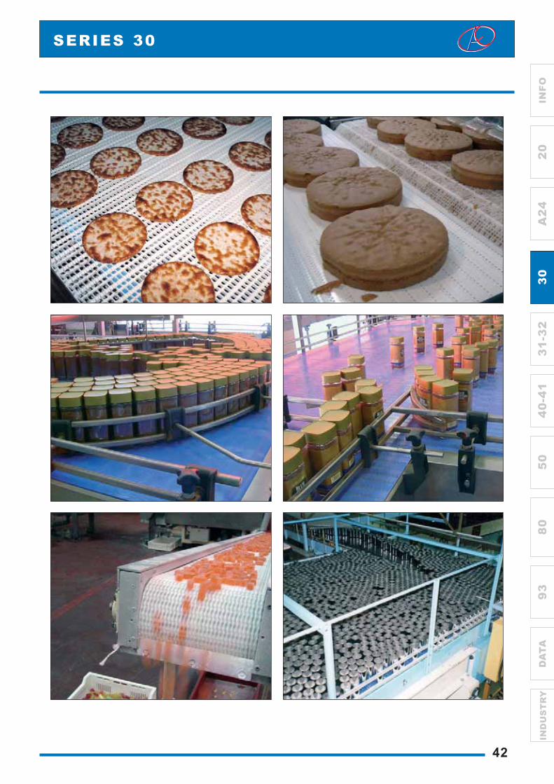
RETAINING RINGSThe fastening of the central sprocket is made byretaining rings manufactured in AISI-316 stainlesssteel. Their design allows an easy installation withoutdismatling or grooving the shaft. They are fastenedthrough a screw that remains perfectly fixed in thering.
We have plastic sprockets for round shaft with andwithout keyway.
We also have sprockets to be used with motor drumin applications needing a special cleaning or inconveyors in which it is not possible to place themotor in the outside due to problems of space orsafety.
SPROCKETS
43
SERIES 30
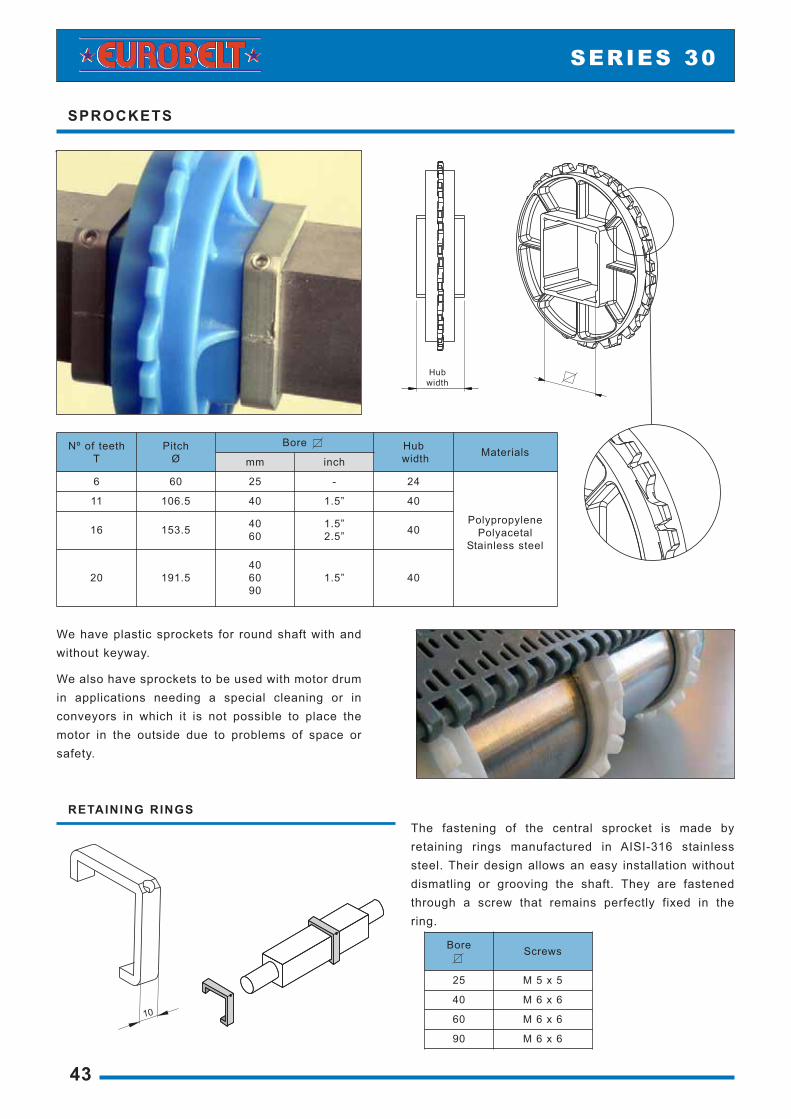
Nº of teeth T
PitchØ
Bore Hubwidth Materials
mm inch
6 60 25 - 24
PolypropylenePolyacetal
Stainless steel
11 106.5 40 1.5” 40
16 153.5 4060
1.5”2.5” 40
20 191.5406090
1.5” 40
Hubwidth
Bore Screws
25 M 5 x 5
40 M 6 x 6
60 M 6 x 6
90 M 6 x 6
44
INF
O3
1-3
23
02
04
0-4
15
08
09
3D
ATA
A2
4IN
DU
ST
RY
SERIES 30
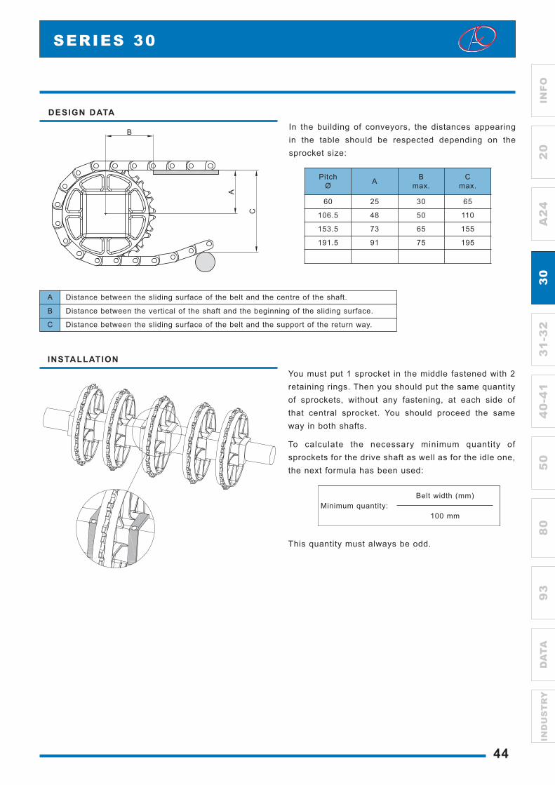
INSTALLATIONYou must put 1 sprocket in the middle fastened with 2retaining rings. Then you should put the same quantityof sprockets, without any fastening, at each side ofthat central sprocket. You should proceed the sameway in both shafts.
To calculate the necessary minimum quantity ofsprockets for the drive shaft as well as for the idle one,the next formula has been used:
This quantity must always be odd.
Belt width (mm)Minimum quantity:
100 mm
DESIGN DATAIn the building of conveyors, the distances appearingin the table should be respected depending on thesprocket size:
PitchØ A B
max.C
max.
60 25 30 65
106.5 48 50 110
153.5 73 65 155
191.5 91 75 195
A Distance between the sliding surface of the belt and the centre of the shaft.
B Distance between the vertical of the shaft and the beginning of the sliding surface.
C Distance between the sliding surface of the belt and the support of the return way.
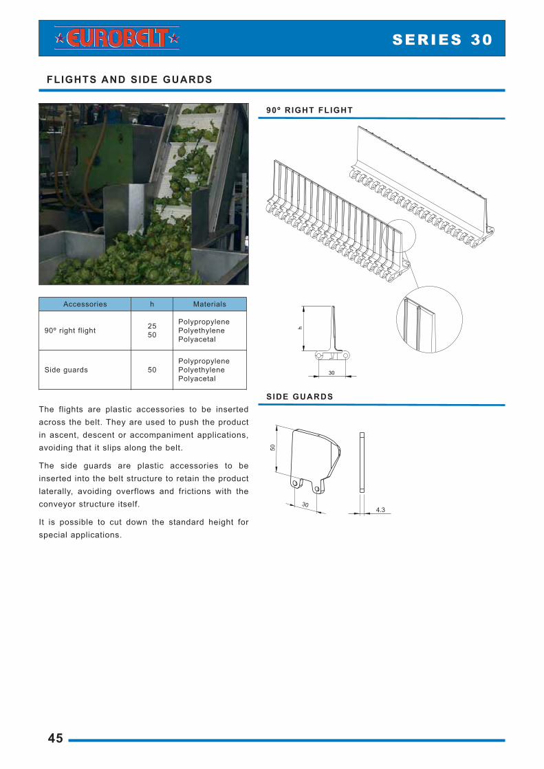
90º RIGHT FLIGHT
FLIGHTS AND SIDE GUARDS
45
SERIES 30
Accessories h Materials
90º right flight 2550
PolypropylenePolyethylenePolyacetal
Side guards 50PolypropylenePolyethylenePolyacetal
The flights are plastic accessories to be insertedacross the belt. They are used to push the productin ascent, descent or accompaniment applications,avoiding that it slips along the belt.
The side guards are plastic accessories to beinserted into the belt structure to retain the productlaterally, avoiding overflows and frictions with theconveyor structure itself.
It is possible to cut down the standard height forspecial applications.
SIDE GUARDS

46
INF
O3
1-3
23
02
04
0-4
15
08
09
3D
ATA
A2
4IN
DU
ST
RY
SERIES 30
BELT ONLY WITH FLIGHTSThe distance between the side edges of the beltand the flights (indent) must be a multiple of 10mm, being 20 mm the minimum.
The pitch of flights along the belt will be amultiple of 60 mm.
BELT WITH FLIGHTS AND SIDE GUARDSIf the belt has both Flights and Side Guards, theminimum distance between them (A) will be:
- 10 mm if the indent is a multiple of 10 mm(minimum indent to be 20 mm)
- 5 mm if the indent is a multiple of 10 mm + 5(minimum indent to be 25 mm)

FINGER PLATES
47
SERIES 30
They have been designed to be used with theRaised Rib belts in applications in which it isnecessary to transfer the product by means offinger plates.
The finger plates are manufactured in nylon andhave 15 teeth. These teeth couple perfectly amongthe projecting ribs of the belt, allowing the constantflow of product as the belt is engaged. They avoidthe use of conventional dead plates andconsequently the problems by stumbling and fall ofthe product.
They have three fastening holes that enable littledisplacements to achieve a better coupling with thebelt.
Those holes are located so that they reduce to theminimum the vibrations owing to the turn of the beltover the sprockets.
The finger plates can be easily installed in thestructure of the conveyor putting a screw in eachhole. The dimensions of these screws are: M 6 x 19mm.
Materials Colours Nº of teeth Nº of holes Screwdimension
Nylon Black15 3 6 x 19
Polyacetal Grey
DESIGN DATA
INSTALLATION

HOLD-DOWN PROFILES AND WEARSTRIPS
48
INF
O3
1-3
23
02
04
0-4
15
08
09
3D
ATA
A2
4IN
DU
ST
RY
To make the fastening and the support of the belt,EUROBELT has designed two types of hold-downprofiles, with different geometries, but with thesame uses and services.
These profiles, with a low coefficient of friction, areplaced between the belt and the structure of theconveyor, reducing the wear of the surfaces incontact, which contributes to prolong the life of thebelt.
EUROBELT offers all the hold-down profiles inspecial polyethylenes, with very good slidingproperties and an excellent resistance to impact.
The flat wearstrips are fastened by means of flat-headed plastic screws, which provides a smoothsurface free of any possibility of hooking. Thedimensions of those screws are: M 6 x 25 mm.
Due to their dovetail design, they can adapt topossible longitudinal contractions and expansionsof the belt.
With regard to the wearstrips arrangement, youshould choose an appropriate configurationaccording to the transport requirements.
The distance between supports should not exceed180 mm in the transport way or 200 mm in thereturn way.
SERIES 30
PROFILES IN L
PROFILES IN U
WEARSTRIPS
Accessories Dimensions Materials
Profiles in L 40 X 20 X 2,00035 X 12 X 2,000 Polyethylene
Profiles in U 20 X 30 X 2,00020 X 14 X 2,000 Polyethylene
Wearstrips 6 x 32 x 500PolyacetalPolyethyleneConductive polyethylene

TABLE OF SPROCKETS AND WEARSTRIPS
49
SERIES 30
To calculate the minimum quantity ofsprockets required both in the driveshaft and in the idle one, you shoulddivide the belt width (in mm) by 100mm.
This amount must always be odd
To calculate the quantity of supports,the weight of the product to betransported must be taken intoaccount.
The distance between supports shouldnot exceed 180 mm in the transportway or 200 mm in the return way.
Belt nominalwidth (mm)
Minimum quantity ofsprockets per shaft
Minimum quantityof wearstrips
Transport way Return way
40 100 1 2 2
101 300 3 2 2
301 500 5 4 3
501 700 7 6 4
701 900 9 8 5
901 1,100 11 10 6
1,101 1,300 13 12 7
1,301 1,500 15 14 8
1,501 1,700 17 16 9
1,701 1,900 19 18 11
1,901 2,100 21 20 12
2,101 2,300 23 22 13
2,301 2,500 25 24 14
2,501 2,700 27 26 15
2,701 2,900 29 28 16
2,901 3,100 31 30 17
3,101 3,300 33 32 18
3,301 3,500 35 34 19
3,501 3,700 37 36 21
3,701 3,900 39 38 22
3,901 4,100 41 40 23

The EUROBELT belts of only one moduleare more noiseless and lighter than thechain lines.
Their maintenance is considerablyreduced as it is not necessary the use ofany type of lubricant to obtain a goodperformance.
Lateral transfer without accidental fallscaused by overturning - No need to useany transfer element - Better stability andexcellent movement of containers
Maximum resistance in the accumulationof containers - Avoids damages on thecontainers' surface
High speed lines with no need of usinglubrication - Better working conditions- Considerable reduction of costs - Nomore problems with wet containers
SE
RIE
S 3
1 -
32
Pitch 30 mm
Lower guides 8 mm
Drive system Central
Belt width - Series 31 152,4 mm
Belt width - Series 32 82,5 - 114,3 - 152,4 - 190,5 mm
Rod diameter Ø 4.6 mm
LATERAL TRANSFER FLAT TOP
Lowerguides
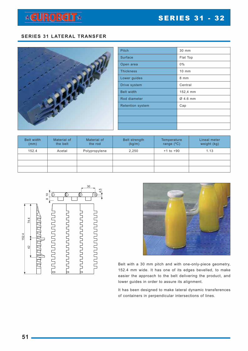
Belt with a 30 mm pitch and with one-only-piece geometry,152.4 mm wide. It has one of its edges bevelled, to makeeasier the approach to the belt delivering the product, andlower guides in order to assure its alignment.
It has been designed to make lateral dynamic transferencesof containers in perpendicular intersections of lines.
SERIES 31 LATERAL TRANSFER
51
SERIES 31 - 32
Pitch 30 mm
Surface Flat Top
Open area 0%
Thickness 10 mm
Lower guides 8 mm
Drive system Central
Belt width 152,4 mm
Rod diameter Ø 4.6 mm
Retention system Cap
Belt width (mm)
Material of the belt
Material of the rod
Belt strength(kg/m)
Temperature range (ºC)
Lineal meterweight (kg)
152.4 Acetal Polypropylene 2,250 +1 to +90 1.13

Belt with 30 mm pitch and with ageometry of only one part in differentwidths: 82,5 – 114,3 – 152,4 – 190,5mm.
It has two lower guides to keep thebelt aligned by counteracting the sideforces.
SERIES 32 FLAT TOP
52
INF
O3
1-3
23
02
04
0-4
15
08
09
3D
ATA
A2
4IN
DU
ST
RY
SERIES 31 - 32
Pitch 30 mm
Surface Flat Top
Open area 0%
Thickness 10 mm
Lower guides 8 mm
Drive system Central
Rod diameter Ø 4.6 mm
Retention system Cap
Belt width (mm)
Material of the belt
Material of the rod
Belt strength(kg/m)
Temperature range (ºC)
Lineal meterweight (kg)
82.5 Polyacetal Polypropylene 2,250 +1 to +90 0.70
114.3 Polyacetal Polypropylene 2,250 +1 to +90 0.90
152.4 Polyacetal Polypropylene 2,250 +1 to +90 1.15
190.5 Polyacetal Polypropylene 2,250 +1 to +90 1.43

RETAINING RINGSThe fastening of the central sprocket is made byretaining rings manufactured in AISI-316 stainlesssteel. Their design allows an easy installation withoutdismantling or grooving the shaft. They are fastenedthrough a screw that remains perfectly fixed in thering.
We have plastic sprockets for round shaft with andwithout keyway.
We also have sprockets to be used with motor drumin applications needing a special cleaning or inconveyors in which it is not possible to place themotor in the outside due to problems of space orsafety.
Hubwidth
SPROCKETS
53
SERIES 31 - 32
Nº of teeth T
PitchØ
Bore Hubwidth Materials
mm inch
6 60 25 - 24
PolypropylenePolyacetal
Stainless steel
11 106.5 40 1.5” 40
16 153.5 4060
1.5”2.5” 40
20 191.5406090
1.5” 40
Bore Screws
25 M 5 x 5
40 M 6 x 6
60 M 6 x 6
90 M 6 x 6

54
INF
O3
1-3
23
02
04
0-4
15
08
09
3D
ATA
A2
4IN
DU
ST
RY
SERIES 31 - 32
INSTALLATIONYou must put 1 sprocket in the middle fastened with 2retaining rings. Then you should put the same quantityof sprockets, without any fastening, at each side ofthat central sprocket. You should proceed the sameway in both shafts.
DESIGN DATAIn the building of conveyors, the distances appearingin the table should be respected depending on thesprocket size:
ØPitch A B
max.C
max.
60 25 30 65
106.5 48 50 110
153.5 73 65 155
191.5 91 75 195
A Distance between the sliding surface of the belt and the centre of the shaft.
B Distance between the vertical of the shaft and the beginning of the sliding surface.
C Distance between the sliding surface of the belt and the support of the return way.

By using the Series 31 Lateral-Transfer Flat Top, dynamicand smooth lateral transferences can be carried out withno need of finger plates.
With one of its edges bevelled we manage to bring nearerthe belts taking part in the transference, whereas thelower guides keep the belt aligned.
It has been designed for those applications in which wewant to avoid the retention of containers in thetransference area as well as to achieve more efficiency intheir movement.
TRANSFERENCES WITH BELT
55
SERIES 31 - 32

OPEN GRID
SERIES
AFHER EUROBELT S.A.Topacio,41 47012 Valladolid SpainPhone: +34 983 217 480 Fax: +34 983 217 481e-mail: [email protected]: www.eurobelt.com
Special for product-in-bulk processes in inclined planes when the use of conventional flights is not possible.
It makes easier the transference, reduces the unevenness of unloading, and avoids the loss of product in the belt return.
These mini-flights reduce the contact surface between product and belt, decreasing the adherence in processes like fish glazing and transport of frozen fish.
Open surface with mini-flights, it is perfect for fish and seafood industry.
SERIES E30 OPEN GRID
C O N V E Y O R B E LT S
glazing
elevation
cooling
boiling
unfreezing

5
30
98
30
AFHER EUROBELT S.A.Topacio,41 47012 - Valladolid (Spain)Phone: +34 983 217 480 Fax: +34 983 217 481e-mail: [email protected]: www.eurobelt.com
SERIES E30 OPEN GRID
DISTRIBUTOR:
[C1-2008] Depósito Legal: VA-1205-2008
BELT DATA
Pitch30 mm
Open area41%
Material of the beltPolypropylenePolyethylenePolyacetal
Belt width Multiples of 10 mm
Spacing between edgesMultiples of 30 mm
Their mini-flights help product in bulk to elevate and descend.
The great open area allows an excellent l iquid drainage and an easy cleaning during maintenance operations.
I t is manufactured in polypropylene, polyethylene and polyacetal. These materials obser ve the International Regulations for their use in food processes.
The minimum spacing between the transversal edges is 30 mm and it can be increased in multiples of 30 mm.

FLAT FRICTION TOP
TRIAN FRICTION TOP
Designed for providing an excellent adherence between product and belt to solve transport problems in inclined planes.
FRICTION TOP BELTS
SERIES
C O N V E Y O R B E LT S
bags
tyres
trays
containers
cartons
shrink-wrappings
baggage
metallic plates
glass
AFHER EUROBELT S.A.Topacio,41 47012 Valladolid SpainPhone: +34 983 217 480 Fax: +34 983 217 481e-mail: [email protected]: www.eurobelt.com
Friction Top surfaces succeed in combining plastic and rubber in one only piece taking advantage both of the modular system and of the adherence.
Both surfaces are manufactured in three Shore grades: A45, A55 and A64, covering a wide range between two different features, adherence and wear.

TRIAN FRIC TION TOPFLAT FRIC TION TOP
30
5
30
5
FRICTION TOP BELTS
[C1-2008] Depósito Legal: VA-1208-2008
AFHER EUROBELT S.A.Topacio,41 47012 - Valladolid (Spain)Phone: +34 983 217 480 Fax: +34 983 217 481e-mail: [email protected]: www.eurobelt.com
DISTRIBUTOR:
Plastic
Rubber
Shore A45 Shore A55 Shore A64
Rubber hardness grades
Plastic colour
Rubber colour
Belt strength
Temperature range
Approved by the FDA
Grey
Black
1,100 kg/m
+1 to + 103 ºC
no
White
Beige
1,100 kg/m
+1 to + 103 ºC
yes
Grey
Beige
1,100 kg/m
+1 to + 103 ºC
yes
BELT DATA
Plastic
Rubber
24.5
Trian Friction Top, designed with small transversal triangles, like mini flights, enables as well an easy and efficient cleaning.
Flat Friction Top, with a flat rubber surface, is perfect for applications in which a maximum adherence is needed.
Material: PolypropylenePolyethylene
Belt width:Multiples of 10 mm
Spacing of rubber lines:It can be assembled with all lines in rubber or spacing them in multiples of 30 mm