Embed Size (px)
Citation preview
FlashHVL-F58AM
© 2008 Sony Corporation
4-105-930-11(1)
Operating Instructions
2
Before operating the product, please read this manual thoroughly and retain it for future reference.
To reduce fire or shock hazard, do not expose the unit to rain or moisture.
Tape over lithium battery contacts to avoid short-circuit when disposing of batteries, and follow local regulations for battery disposal.
Keep batteries or things that could be swallowed away from young children. Contact a doctor immediately if an object is swallowed.
Immediately remove the batteries and discontinue use if...• the product is dropped or subjected to an impact in which the interior is exposed. • the product emits a strange smell, heat, or smoke.
Do not disassemble. Electric shock may occur if a high voltage circuit inside the product is touched.
IMPORTANT SAFETY INSTRUCTIONSWhen using your photographic equipment, basic safety precautions should always be followed, including the following:Read and understand all instructions before using.Close supervision is necessary when any appliance is used by or near children. Do not leave appliance unattended while in use.Care must be taken as burns can occur from touching hot parts.
English
WARNING
3
Do not operate appliance with a damaged cord or if the appliance has been dropped or damaged- until it has been examined by a qualified serviceman.Let appliance cool completely before putting away. Loop cord loosely around appliance when storing.To reduce the risk of electric shock, do not immerse this appliance in water or other liquids.To reduce the risk of electric shock, do not disassemble this appliance, but take it to a qualified serviceman when service or repair work is required. Incorrect reassembly can cause electric shock when the appliance is used subsequently.The use of an accessory attachment not recommended by the manufacturer may cause a risk of fire, electric shock, or injury to persons.Batteries may become hot or explode due to improper use. Use only the batteries specified in this instruction manual.Do not install the batteries with the polarity (+/-) reversed.Do not subject batteries to fire or high temperatures.Do not attempt to recharge (except for rechargeable batteries), short or disassemble.Do not mix, batteries of different types, brands or ages.
SAVE THESE INSTRUCTIONSCAUTIONDo not touch the flashtube during operation, it may become hot when the flash fires.
4
For customers in EuropeDisposal of Old Electrical & Electronic Equipment (Applicable in the European Union and other European countries with separate collection systems)This symbol on the product or on its packaging indicates that this product shall not be treated as household waste. Instead it shall be handed over to the applicable collection point for the recycling of electrical and electronic equipment. By ensuring this product is disposed of correctly, you will help prevent potential negative consequences for the environment and human health, which could otherwise be caused by inappropriate waste handling of this product. The recycling of materials will help to conserve natural resources. For more detailed information about recycling of this product, please contact your local Civic Office, your household waste disposal service or the shop where you purchased the product.
Notice for the customers in the countries applying EU DirectivesThe manufacturer of this product is Sony Corporation, 1-7-1 Konan Minato-ku Tokyo, 108-0075 Japan. The Authorized Representative for EMC and product safety is Sony Deutschland GmbH, Hedelfinger Strasse 61, 70327 Stuttgart, Germany. For any service or guarantee matters please refer to the addresses given in separate service or guarantee documents.
For the customers in the U.S.A.
CAUTIONYou are cautioned that any changes or modifications not expressly approved in this manual could void your authority to operate this equipment.
NOTE:This equipment has been tested and found to comply with the limits for a Class B digital device, pursuant to Part 15 of the FCC Rules.These limits are designed to provide reasonable protection against harmful interference in a residential installation.This equipment generates, uses, and can radiate radio frequency energy and, if not installed and used in accordance with the instructions, may cause harmful interference to radio communications.
5
However, there is no guarantee that interference will not occur a particular installation. If this equipment does cause harmful interference to radio or television reception, which can be determined by turning the equipment off and on, the user is encouraged to try to correct the interference by one or more of following measures:– Reorient or relocate the receiving antenna.– Increase the separation between the equipment and receiver.– Connect the equipment into an outlet on a circuit different from that to which the
receiver is connected.– Consult the dealer or an experienced radio/TV technician for help.
6
Table of ContentsFeatures .................................................................................................... 9
Name of parts ........................................................................................ 10
PreparationsInserting batteries .................................................................................. 15
Attachment and removal of the flash unit ............................................. 18
Turning on the power ............................................................................ 20
Changing the flash mode ....................................................................... 22
LCD panel illuminator ........................................................................... 24
BasicsProgram auto flash (The basics) ............................................................ 25
Using flash in each recording mode of the camera ............................... 29
ApplicationsTest-flash ............................................................................................... 31
Zoom flash coverage ............................................................................. 32
Bounce flash .......................................................................................... 36
Close-up photography (downward bounce) .......................................... 41
Manual flash (M) ................................................................................... 43
High-speed sync (HSS) ......................................................................... 47
Multiple flash (MULTI) ........................................................................ 48
Wireless flash mode (WL) ..................................................................... 54
Connecting camera and flash by cable .................................................. 69
Using external battery adaptor ............................................................... 71
AF illuminator ....................................................................................... 72
Reset to the default settings ................................................................... 73
Custom setting ....................................................................................... 74

7
Additional InformationNotes on use .......................................................................................... 81
Maintenance ........................................................................................... 83
Specifications ........................................................................................ 84
8
Before useFor details, refer to the operating instructions supplied with your camera.This flash unit is not dust-proof, splash-proof or waterproof.Do not place this flash unit in the following locationsRegardless of whether this flash unit is in use or in storage, do not place it in any of the following locations. Doing so may lead to a malfunction.• Placing this flash unit in locations subject to direct sunlight such as on
dashboards or near a heater may cause this unit to deform or malfunction.• Locations with excessive vibration• Locations with strong electromagnetism• Locations with excessive sand
In locations such as the seashore and other sandy areas or where dust clouds occur, protect the unit from sand and dust.This may lead to a malfunction.
9
Features
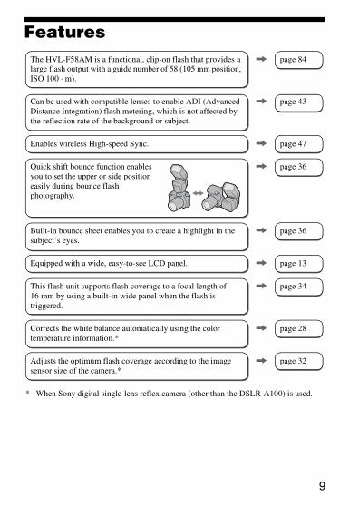
* When Sony digital single-lens reflex camera (other than the DSLR-A100) is used.
The HVL-F58AM is a functional, clip-on flash that provides a large flash output with a guide number of 58 (105 mm position, ISO 100 · m).
, page 84
Can be used with compatible lenses to enable ADI (Advanced Distance Integration) flash metering, which is not affected by the reflection rate of the background or subject.
, page 43
Enables wireless High-speed Sync. , page 47
Quick shift bounce function enables you to set the upper or side position easily during bounce flash photography.
, page 36
Built-in bounce sheet enables you to create a highlight in the subject’s eyes.
, page 36
Equipped with a wide, easy-to-see LCD panel. , page 13
This flash unit supports flash coverage to a focal length of 16 mm by using a built-in wide panel when the flash is triggered.
, page 34
Corrects the white balance automatically using the color temperature information.*
, page 28
Adjusts the optimum flash coverage according to the image sensor size of the camera.*
, page 32
10
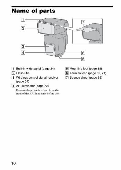
Name of parts
A Built-in wide panel (page 34)
B Flashtube
C Wireless control signal receiver (page 54)
D AF illuminator (page 72)Remove the protective sheet from the front of the AF illuminator before use.
E Mounting foot (page 18)
F Terminal cap (page 69, 71)
G Bounce sheet (page 36)
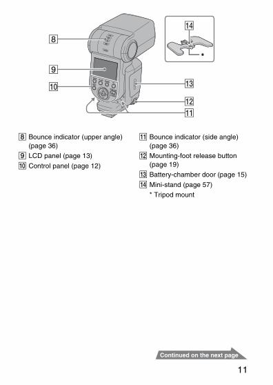
11
H Bounce indicator (upper angle) (page 36)
I LCD panel (page 13)
J Control panel (page 12)
K Bounce indicator (side angle) (page 36)
L Mounting-foot release button (page 19)
M Battery-chamber door (page 15)
N Mini-stand (page 57)
* Tripod mount
*
12
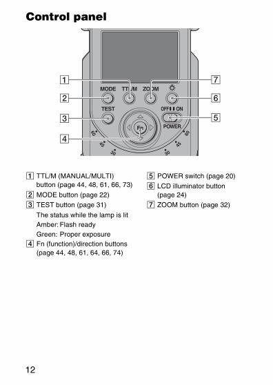
Control panel
A TTL/M (MANUAL/MULTI) button (page 44, 48, 61, 66, 73)
B MODE button (page 22)
C TEST button (page 31)
The status while the lamp is litAmber: Flash readyGreen: Proper exposure
D Fn (function)/direction buttons (page 44, 48, 61, 64, 66, 74)
E POWER switch (page 20)
F LCD illuminator button (page 24)
G ZOOM button (page 32)
13
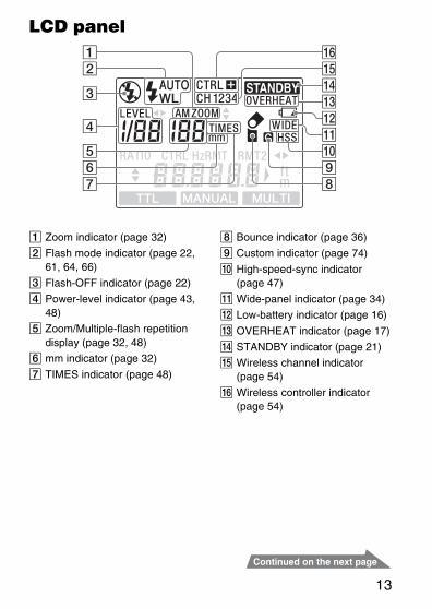
LCD panel
A Zoom indicator (page 32)
B Flash mode indicator (page 22, 61, 64, 66)
C Flash-OFF indicator (page 22)
D Power-level indicator (page 43, 48)
E Zoom/Multiple-flash repetition display (page 32, 48)
F mm indicator (page 32)
G TIMES indicator (page 48)
H Bounce indicator (page 36)
I Custom indicator (page 74)
J High-speed-sync indicator (page 47)
K Wide-panel indicator (page 34)
L Low-battery indicator (page 16)
M OVERHEAT indicator (page 17)
N STANDBY indicator (page 21)
O Wireless channel indicator (page 54)
P Wireless controller indicator (page 54)
14
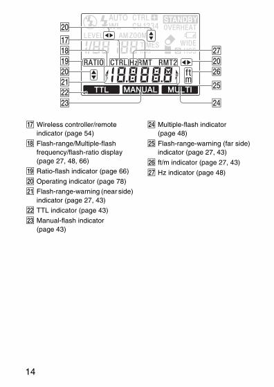
Q Wireless controller/remote indicator (page 54)
R Flash-range/Multiple-flash frequency/flash-ratio display (page 27, 48, 66)
S Ratio-flash indicator (page 66)
T Operating indicator (page 78)
U Flash-range-warning (near side) indicator (page 27, 43)
V TTL indicator (page 43)
W Manual-flash indicator (page 43)
X Multiple-flash indicator (page 48)
Y Flash-range-warning (far side) indicator (page 27, 43)
Z ft/m indicator (page 27, 43)
wj Hz indicator (page 48)
Pre
pa
ratio
ns
15
Preparations
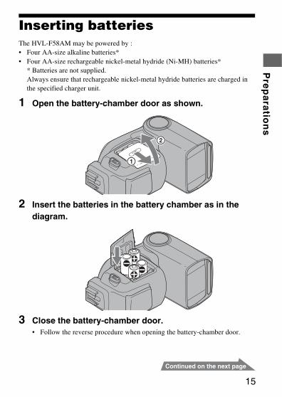
Inserting batteriesThe HVL-F58AM may be powered by :• Four AA-size alkaline batteries*• Four AA-size rechargeable nickel-metal hydride (Ni-MH) batteries*
* Batteries are not supplied.Always ensure that rechargeable nickel-metal hydride batteries are charged in the specified charger unit.
1 Open the battery-chamber door as shown.
2 Insert the batteries in the battery chamber as in the diagram.
3 Close the battery-chamber door.• Follow the reverse procedure when opening the battery-chamber door.
16
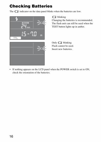
Checking BatteriesThe indicator on the data panel blinks when the batteries are low.
• If nothing appears on the LCD panel when the POWER switch is set to ON, check the orientation of the batteries.
blinkingChanging the batteries is recommended. The flash unit can still be used when the TEST button lights up in amber.
Only blinkingFlash cannot be used.Insert new batteries.
Pre
pa
ratio
ns
17
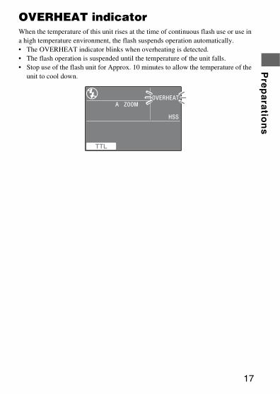
OVERHEAT indicatorWhen the temperature of this unit rises at the time of continuous flash use or use in a high temperature environment, the flash suspends operation automatically.• The OVERHEAT indicator blinks when overheating is detected.• The flash operation is suspended until the temperature of the unit falls.• Stop use of the flash unit for Approx. 10 minutes to allow the temperature of the
unit to cool down.
18
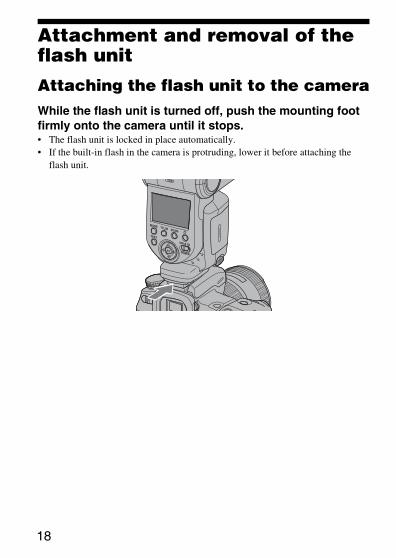
Attachment and removal of the flash unit
Attaching the flash unit to the cameraWhile the flash unit is turned off, push the mounting foot firmly onto the camera until it stops.• The flash unit is locked in place automatically.• If the built-in flash in the camera is protruding, lower it before attaching the
flash unit.
Pre
pa
ratio
ns
19
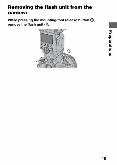
Removing the flash unit from the cameraWhile pressing the mounting-foot release button 1, remove the flash unit 2.
20
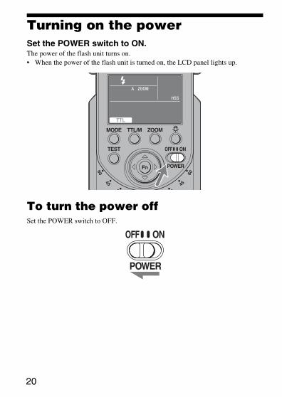
Turning on the powerSet the POWER switch to ON.The power of the flash unit turns on.• When the power of the flash unit is turned on, the LCD panel lights up.
To turn the power offSet the POWER switch to OFF.
Pre
pa
ratio
ns
21
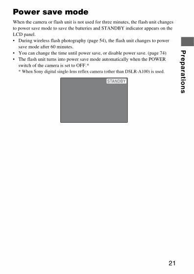
Power save modeWhen the camera or flash unit is not used for three minutes, the flash unit changes to power save mode to save the batteries and STANDBY indicator appears on the LCD panel.• During wireless flash photography (page 54), the flash unit changes to power
save mode after 60 minutes.• You can change the time until power save, or disable power save. (page 74)• The flash unit turns into power save mode automatically when the POWER
switch of the camera is set to OFF.** When Sony digital single-lens reflex camera (other than DSLR-A100) is used.
22
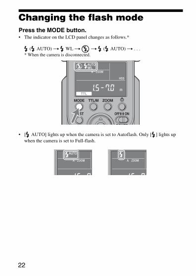
Changing the flash modePress the MODE button.• The indicator on the LCD panel changes as follows.*
( AUTO) t WL t t ( AUTO) t . . .* When the camera is disconnected.
• [ AUTO] lights up when the camera is set to Autoflash. Only [ ] lights up when the camera is set to Full-flash.
Pre
pa
ratio
ns
23
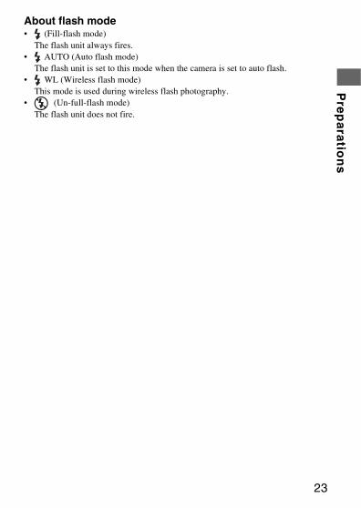
About flash mode• (Fill-flash mode)
The flash unit always fires.• AUTO (Auto flash mode)
The flash unit is set to this mode when the camera is set to auto flash.• WL (Wireless flash mode)
This mode is used during wireless flash photography.• (Un-full-flash mode)
The flash unit does not fire.
24
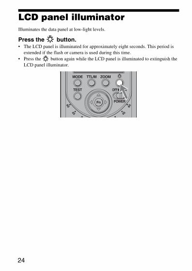
LCD panel illuminatorIlluminates the data panel at low-light levels.
Press the button.• The LCD panel is illuminated for approximately eight seconds. This period is
extended if the flash or camera is used during this time.• Press the button again while the LCD panel is illuminated to extinguish the
LCD panel illuminator.
Ba
sic
s
25
Basics
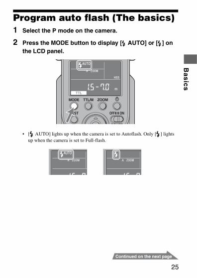
Program auto flash (The basics)1 Select the P mode on the camera.
2 Press the MODE button to display [ AUTO] or [ ] on the LCD panel.
• [ AUTO] lights up when the camera is set to Autoflash. Only [ ] lights up when the camera is set to Full-flash.
26
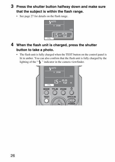
3 Press the shutter button halfway down and make sure that the subject is within the flash range.• See page 27 for details on the flash range.
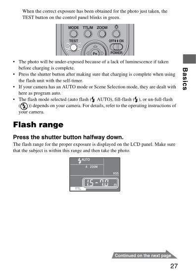
4 When the flash unit is charged, press the shutter button to take a photo.• The flash unit is fully charged when the TEST button on the control panel is
lit in amber. You can also confirm that the flash unit is fully charged by the lighting of the “ ” indicator in the camera viewfinder.
Ba
sic
s
27
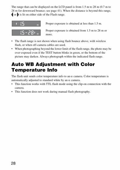
When the correct exposure has been obtained for the photo just taken, the TEST button on the control panel blinks in green.
• The photo will be under-exposed because of a lack of luminescence if taken before charging is complete.
• Press the shutter button after making sure that charging is complete when using the flash unit with the self-timer.
• If your camera has an AUTO mode or Scene Selection mode, they are dealt with here as program auto.
• The flash mode selected (auto flash ( AUTO), fill-flash ( ), or un-full-flash ( )) depends on your camera. For details, refer to the operating instructions of your camera.
Flash rangePress the shutter button halfway down.The flash range for the proper exposure is displayed on the LCD panel. Make sure that the subject is within this range and then take the photo.
28
The range that can be displayed on the LCD panel is from 1.5 m to 28 m (0.7 m to 28 m for downward bounce; see page 41). When the distance is beyond this range,
or is lit on either side of the Flash range.
• The flash range is not shown when using flash bounce above, with wireless flash, or when off-camera cables are used.
• When photographing beyond the lower limit of the flash range, the photo may be over-exposed even if the TEST button blinks in green, or the bottom of the picture may darken. Always photograph within the indicated flash range.
Auto WB Adjustment with Color Temperature InfoThe flash unit sends color temperature info to an α camera. Color temperature is automatically adjusted to standard white by an α camera.• This function works with TTL flash mode using the clip-on connection with the
camera.• This function does not work during manual flash photography.
Proper exposure is obtained at less than 1.5 m.
Proper exposure is obtained from 1.5 m to 28 m or more.
Ba
sic
s
29
Using flash in each recording mode of the cameraThis section explains how to use the flash unit in each recording mode of the camera.
Aperture priority flash photography (A)1 Select the A mode on the camera.
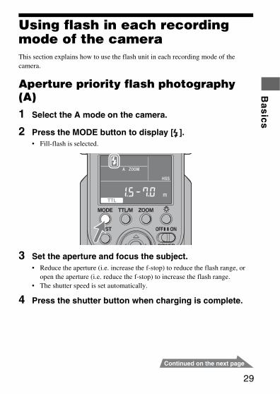
2 Press the MODE button to display [ ].• Fill-flash is selected.
3 Set the aperture and focus the subject.• Reduce the aperture (i.e. increase the f-stop) to reduce the flash range, or
open the aperture (i.e. reduce the f-stop) to increase the flash range.• The shutter speed is set automatically.
4 Press the shutter button when charging is complete.
30
Shutter speed priority flash photography (S)1 Select the S mode on the camera.
2 Press the MODE button to display [ ].• Fill-flash is selected.
3 Set the shutter speed, and focus the subject.
4 Press the shutter button when charging is complete.
Manual exposure mode flash photography (M)1 Select the M mode on the camera.
2 Press the MODE button to display [ ].• Fill-flash is selected.
3 Set the aperture and shutter speed, and focus the subject.• Reduce the aperture (i.e. increase the f-stop) to reduce the flash range, or
open the aperture (i.e. reduce the f-stop) to increase the flash range.
4 Press the shutter button when charging is complete.
Ap
plic
atio
ns
31
Applications
Test-flashYou can try a test flash before shooting. Check the light level using the test flash when you use a flash meter, etc., in the manual flash (M) mode.
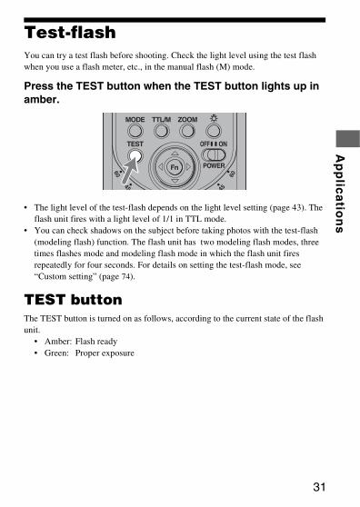
Press the TEST button when the TEST button lights up in amber.
• The light level of the test-flash depends on the light level setting (page 43). The flash unit fires with a light level of 1/1 in TTL mode.
• You can check shadows on the subject before taking photos with the test-flash (modeling flash) function. The flash unit has two modeling flash modes, three times flashes mode and modeling flash mode in which the flash unit fires repeatedly for four seconds. For details on setting the test-flash mode, see “Custom setting” (page 74).
TEST buttonThe TEST button is turned on as follows, according to the current state of the flash unit.
• Amber: Flash ready• Green: Proper exposure
32
Zoom flash coverage
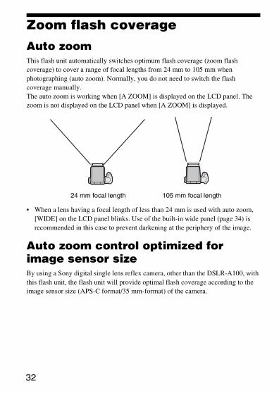
Auto zoomThis flash unit automatically switches optimum flash coverage (zoom flash coverage) to cover a range of focal lengths from 24 mm to 105 mm when photographing (auto zoom). Normally, you do not need to switch the flash coverage manually.The auto zoom is working when [A ZOOM] is displayed on the LCD panel. The zoom is not displayed on the LCD panel when [A ZOOM] is displayed.
• When a lens having a focal length of less than 24 mm is used with auto zoom, [WIDE] on the LCD panel blinks. Use of the built-in wide panel (page 34) is recommended in this case to prevent darkening at the periphery of the image.
Auto zoom control optimized for image sensor sizeBy using a Sony digital single lens reflex camera, other than the DSLR-A100, with this flash unit, the flash unit will provide optimal flash coverage according to the image sensor size (APS-C format/35 mm-format) of the camera.
24 mm focal length 105 mm focal length
Ap
plic
atio
ns
33
Manual zoomYou can manually set the flash coverage regardless of the focal length of the lens in use (manual zoom).
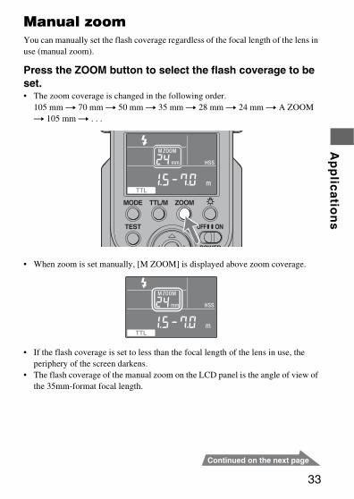
Press the ZOOM button to select the flash coverage to be set.• The zoom coverage is changed in the following order.
105 mm t 70 mm t 50 mm t 35 mm t 28 mm t 24 mm t A ZOOM t 105 mm t . . .
• When zoom is set manually, [M ZOOM] is displayed above zoom coverage.
• If the flash coverage is set to less than the focal length of the lens in use, the periphery of the screen darkens.
• The flash coverage of the manual zoom on the LCD panel is the angle of view of the 35mm-format focal length.
34
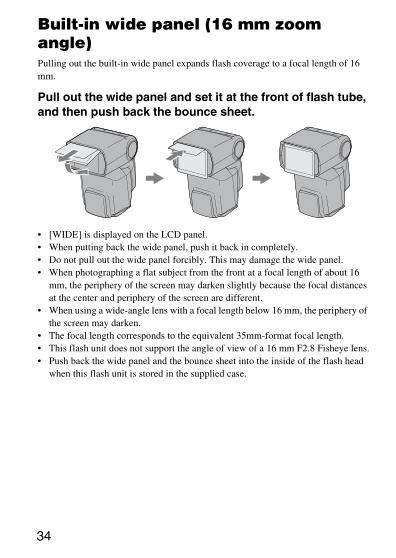
Built-in wide panel (16 mm zoom angle)Pulling out the built-in wide panel expands flash coverage to a focal length of 16 mm.
Pull out the wide panel and set it at the front of flash tube, and then push back the bounce sheet.
• [WIDE] is displayed on the LCD panel.• When putting back the wide panel, push it back in completely.• Do not pull out the wide panel forcibly. This may damage the wide panel.• When photographing a flat subject from the front at a focal length of about 16
mm, the periphery of the screen may darken slightly because the focal distances at the center and periphery of the screen are different.
• When using a wide-angle lens with a focal length below 16 mm, the periphery of the screen may darken.
• The focal length corresponds to the equivalent 35mm-format focal length.• This flash unit does not support the angle of view of a 16 mm F2.8 Fisheye lens.• Push back the wide panel and the bounce sheet into the inside of the flash head
when this flash unit is stored in the supplied case.
Ap
plic
atio
ns
35
Flash coverage & focal lengthThe larger the focal length figure of the lens on a camera, the further away a subject can be photographed to take up the full screen; but the area that can be covered becomes smaller. Conversely, with a smaller focal length figure, subjects can be photographed with wider coverage. The flash coverage is the area that the light from the flash at a set intensity or greater can cover evenly, expressed as an angle. The flash coverage at which you can photograph is determined by the focal length. By having flash coverage determined in accordance with focal length, flash coverage can be expressed as the figure for focal length.
36
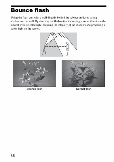
Bounce flashUsing the flash unit with a wall directly behind the subject produces strong shadows on the wall. By directing the flash unit at the ceiling you can illuminate the subject with reflected light, reducing the intensity of the shadows and producing a softer light on the screen.
Bounce flash Normal flash
Ap
plic
atio
ns
37
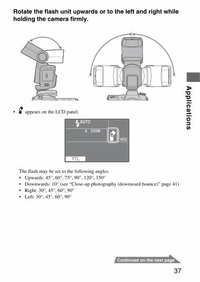
Rotate the flash unit upwards or to the left and right while holding the camera firmly.
• appears on the LCD panel.
The flash may be set to the following angles.• Upwards: 45°, 60°, 75°, 90°, 120°, 150°• Downwards: 10° (see “Close-up photography (downward bounce)” page 41)• Right: 30°, 45°, 60°, 90°• Left: 30°, 45°, 60°, 90°
38
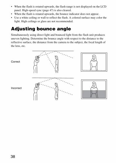
• When the flash is rotated upwards, the flash range is not displayed on the LCD panel. High-speed sync (page 47) is also cleared.
• When the flash is rotated upwards, the bounce indicator does not appear.• Use a white ceiling or wall to reflect the flash. A colored surface may color the
light. High ceilings or glass are not recommended.
Adjusting bounce angleSimultaneously using direct light and bounced light from the flash unit produces uneven lighting. Determine the bounce angle with respect to the distance to the reflective surface, the distance from the camera to the subject, the focal length of the lens, etc.
Correct
Incorrect
Ap
plic
atio
ns
39
When the flash is bounced upwards Determine the angle in relation to the following table.
Using the bounce sheetThe bounce sheet creates a highlight in the subject's eyes and makes the subject look more vibrant.• The bounce sheet is pulled out when the wide panel is pulled out. Push back the
wide panel.• When using the bounce sheet, set the bounce angle to 90° upwards.
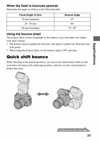
Quick shift bounceWhen shooting in the portrait position, you can set the same bounce flash as that used when shooting in the landscape position, and also use the control panel at proper direction.
Focal length of lens Bounce angle
70 mm minimum 45°
28 - 70 mm 60°
28 mm maximum 75°, 90°
40
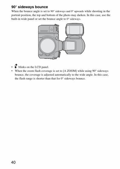
90° sideways bounceWhen the bounce angle is set to 90° sideways and 0° upwards while shooting in the portrait position, the top and bottom of the photo may darken. In this case, use the built-in wide panel or set the bounce angle to 0° sideways.
• blinks on the LCD panel.• When the zoom flash coverage is set to [A ZOOM] while using 90° sideways
bounce, the coverage is adjusted automatically to the wide angle. In this case, the flash range is shorter than that for 0° sideways bounce.
Ap
plic
atio
ns
41
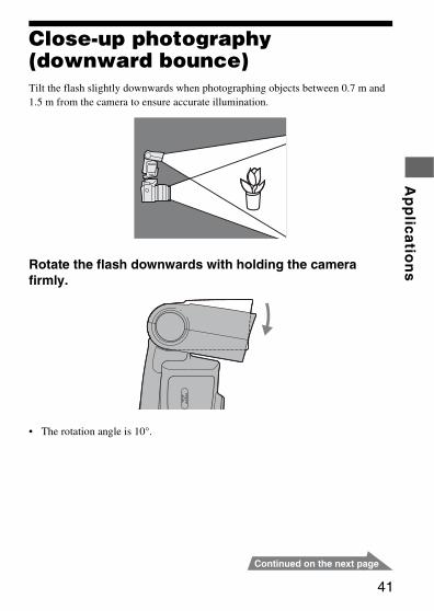
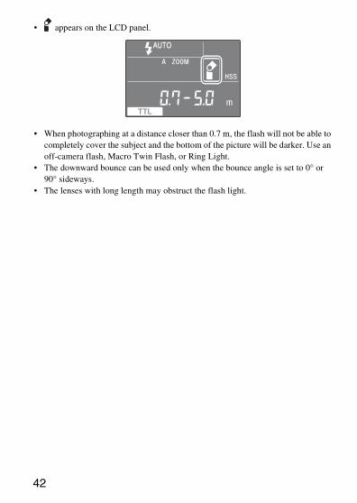
Close-up photography (downward bounce)Tilt the flash slightly downwards when photographing objects between 0.7 m and 1.5 m from the camera to ensure accurate illumination.
Rotate the flash downwards with holding the camera firmly.
• The rotation angle is 10°.
42
• appears on the LCD panel.
• When photographing at a distance closer than 0.7 m, the flash will not be able to completely cover the subject and the bottom of the picture will be darker. Use an off-camera flash, Macro Twin Flash, or Ring Light.
• The downward bounce can be used only when the bounce angle is set to 0° or 90° sideways.
• The lenses with long length may obstruct the flash light.
Ap
plic
atio
ns
43
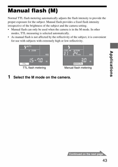
Manual flash (M)Normal TTL flash metering automatically adjusts the flash intensity to provide the proper exposure for the subject. Manual flash provides a fixed flash intensity irrespective of the brightness of the subject and the camera setting.• Manual flash can only be used when the camera is in the M mode. In other
modes, TTL measuring is selected automatically.• As manual flash is not affected by the reflectivity of the subject, it is convenient
for use with subjects with extremely high or low reflectivity.
1 Select the M mode on the camera.
TTL flash metering Manual flash metering
44
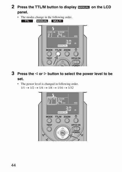
2 Press the TTL/M button to display on the LCD panel.• The modes change in the following order.
, ,
3 Press the g or G button to select the power level to be set.• The power level is changed in following order.
1/1 t 1/2 t 1/4 t 1/8 t 1/16 t 1/32
Ap
plic
atio
ns
45
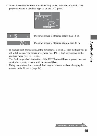
• When the shutter button is pressed halfway down, the distance at which the proper exposure is obtained appears on the LCD panel.
• In manual flash photography, if the power level is set at 1/1 then the flash will go off at full power. The power level range (e.g. 1/1 t 1/2) corresponds to the aperture range (e.g. F4 t 5.6).
• The flash range check indication of the TEST button (blinks in green) does not work after a photo is taken with the manual flash.
• Using custom functions, manual flash may be selected without changing the camera to the M mode (page 74).
Proper exposure is obtained at less than 1.5 m.
Proper exposure is obtained at more than 28 m.
46
TTL flashManual flash provides a fixed flash intensity irrespective of the brightness of the subject and the camera setting. TTL* flash measures the light from the subject that is reflected through the lens.TTL metering also has a P-TTL metering function, which adds a pre-flash to TTL metering, and an ADI metering function, which adds distance data to the P-TTL metering.This flash unit defines all P-TTL and ADI metering as TTL flash and
is displayed on the LCD panel.*TTL = through the lens• ADI metering is possible in combination with a lens with a built-in distance
encoder. Before using the ADI metering function, check whether your lens has a built-in distance encoder by referring to the specifications in the operating instructions supplied with your lens.
Ap
plic
atio
ns
47
High-speed sync (HSS)
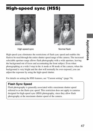
High-speed sync eliminates the restrictions of flash sync speed and enables the flash to be used through the entire shutter speed range of the camera. The increased selectable aperture range allows flash photography with a wide aperture, leaving the background out of focus and accentuating the front subject. Even when photographing at a wide f-stop in the A mode or M mode of the camera, when the background is very bright and the shot will normally be over-exposed, you can adjust the exposure by using the high-speed shutter.
For details on setting the HSS features, see “Custom setting” (page 74).
High-speed sync Normal flash
Flash Sync SpeedFlash photography is generally associated with a maximum shutter speed referred to as the flash sync speed. This restriction does not apply to cameras designed for high-speed sync (HSS) photography, since they allow flash photography at the maximum shutter speed of the camera.
48
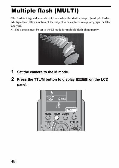
Multiple flash (MULTI)The flash is triggered a number of times while the shutter is open (multiple flash). Multiple flash allows motion of the subject to be captured in a photograph for later analysis.• The camera must be set to the M mode for multiple flash photography.
1 Set the camera to the M mode.
2 Press the TTL/M button to display on the LCD panel.
Ap
plic
atio
ns
49
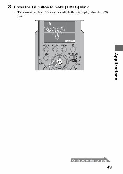
3 Press the Fn button to make [TIMES] blink.• The current number of flashes for multiple flash is displayed on the LCD
panel.
50
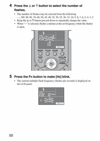
4 Press the f or F button to select the number of flashes.• The number of flashes may be selected from the following.
- -, 100, 90, 80, 70, 60, 50, 45, 40, 35, 30, 25, 20, 15, 10, 9, 8, 7, 6, 5, 4, 3, 2• Keep the f or F button pressed down to repeatedly change the value.• When “--” is selected, flashes continue at the set frequency while the shutter
is open.
5 Press the Fn button to make [Hz] blink.• The current multiple flash frequency (flashes per second) is displayed on
the LCD panel.
Ap
plic
atio
ns
51
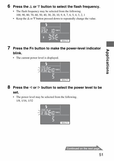
6 Press the f or F button to select the flash frequency.• The flash frequency may be selected from the following.
100, 90, 80, 70, 60, 50, 40, 30, 20, 10, 9, 8, 7, 6, 5, 4, 3, 2, 1• Keep the f or F button pressed down to repeatedly change the value.
7 Press the Fn button to make the power-level indicator blink.• The current power level is displayed.
8 Press the g or G button to select the power level to be set.• The power level may be selected from the following.
1/8, 1/16, 1/32
52
9 Press the Fn button.
10 Set the shutter speed and aperture.• The shutter speed is calculated as follows to suit the selected flash
frequency and number of flashes.Number of flashes (TIME) ÷ Flash frequency (Hz) = Shutter speedFor example, when ten flashes and 5 Hz are selected, 10 ÷ 5 = 2 requires a shutter speed of longer than two seconds.
11 When the flash is fully charged, press the shutter button to take the photo.• The distance at which the proper exposure is obtained with a single flash is
displayed on the LCD panel.• To prevent shaking, the use of a tripod is recommended during multiple
flash photography.• Test flash will flash at the selected frequency/number/level while the TEST
button is being pressed if [TEST1] is selected in the custom setting. When [TEST3] or [TESTM] is selected, the flash three times or the four second modeling flash has priority.
• The use of custom settings allows the camera to be set up for multiple flash photography without selecting the M mode (page 74).
Ap
plic
atio
ns
53
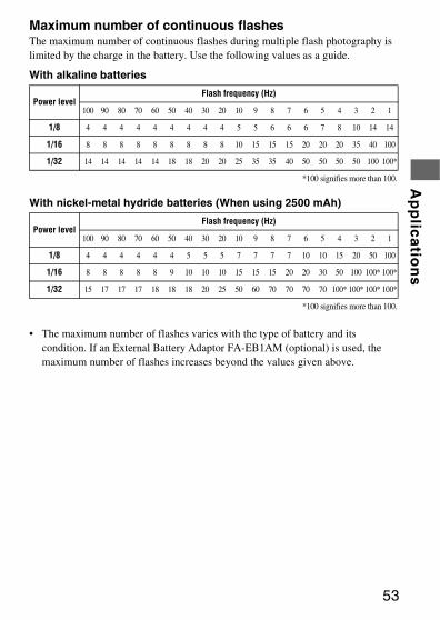
Maximum number of continuous flashesThe maximum number of continuous flashes during multiple flash photography is limited by the charge in the battery. Use the following values as a guide.
With alkaline batteries
With nickel-metal hydride batteries (When using 2500 mAh)
• The maximum number of flashes varies with the type of battery and its condition. If an External Battery Adaptor FA-EB1AM (optional) is used, the maximum number of flashes increases beyond the values given above.
Power levelFlash frequency (Hz)
100 90 80 70 60 50 40 30 20 10 9 8 7 6 5 4 3 2 1
1/8 4 4 4 4 4 4 4 4 4 5 5 6 6 6 7 8 10 14 14
1/16 8 8 8 8 8 8 8 8 8 10 15 15 15 20 20 20 35 40 100
1/32 14 14 14 14 14 18 18 20 20 25 35 35 40 50 50 50 50 100 100*
*100 signifies more than 100.
Power levelFlash frequency (Hz)
100 90 80 70 60 50 40 30 20 10 9 8 7 6 5 4 3 2 1
1/8 4 4 4 4 4 4 5 5 5 7 7 7 7 10 10 15 20 50 100
1/16 8 8 8 8 8 9 10 10 10 15 15 15 20 20 30 50 100 100* 100*
1/32 15 17 17 17 18 18 18 20 25 50 60 70 70 70 70 100* 100* 100* 100*
*100 signifies more than 100.
54
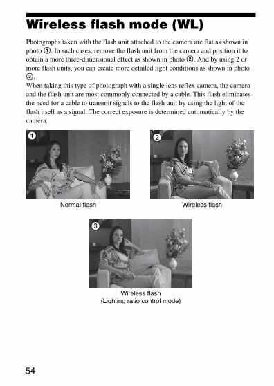
Wireless flash mode (WL)Photographs taken with the flash unit attached to the camera are flat as shown in photo 1. In such cases, remove the flash unit from the camera and position it to obtain a more three-dimensional effect as shown in photo 2. And by using 2 or more flash units, you can create more detailed light conditions as shown in photo 3.When taking this type of photograph with a single lens reflex camera, the camera and the flash unit are most commonly connected by a cable. This flash eliminates the need for a cable to transmit signals to the flash unit by using the light of the flash itself as a signal. The correct exposure is determined automatically by the camera.
Normal flash Wireless flash
Wireless flash(Lighting ratio control mode)
Ap
plic
atio
ns
55
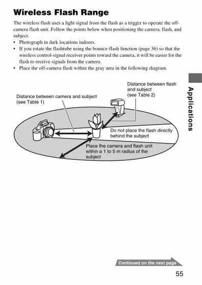
Wireless Flash RangeThe wireless flash uses a light signal from the flash as a trigger to operate the off-camera flash unit. Follow the points below when positioning the camera, flash, and subject.• Photograph in dark locations indoors.• If you rotate the flashtube using the bounce-flash function (page 36) so that the
wireless control-signal receiver points toward the camera, it will be easier for the flash to receive signals from the camera.
• Place the off-camera flash within the gray area in the following diagram.
Distance between camera and subject (see Table 1)
Distance between flash and subject(see Table 2)
Do not place the flash directly behind the subject
Place the camera and flash unit within a 1 to 5 m radius of the subject
56
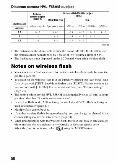
Distance camera-HVL-F58AM-subject
• The distances in the above table assume the use of ISO 100. If ISO 400 is used the distances must be multiplied by a factor of two (assume a limit of 5 m).
• The flash range is not displayed on the LCD panel when using wireless flash.
Notes on wireless flash• You cannot use a flash meter or color meter in wireless flash mode because the
pre-flash goes off.• Test flash for the wireless flash is in the currently selected test flash mode. One
flash occurs with [TEST1] and three flashes with [TEST3]. Flashes continue for four seconds with [TESTM]. For details of test flash, See “Custom setting” (page 74).
• The zoom position for the HVL-F58AM is automatically set to 24 mm. A zoom position other than 24 mm is not recommended.
• In wireless flash mode, ADI metering is canceled and P-TTL flash metering is used automatically (page 43).
• Multiple flash cannot be used.• If another wireless flash is being used nearby, you can change the channel in the
custom settings to prevent interference (page 74).• When photographing with the wireless flash, the flash unit may in rare cases go
off by mistake due to ambient static electricity or electromagnetic noise.When the flash is not in use, select [ ] using the MODE button.
Distance camera-subject
(Table 1)
Distance HVL-F58AM - subject(Table 2)
Other than HSS HSS
Shutter speedAll shutter speeds Sync speed or slower 1/250 sec 1/500 sec 1/1000 sec 1/2000 sec
Aperture
2.8 1.4 - 5 1.4 - 5 1 - 3.5 1 - 2.5 1 - 1.7 1 - 1.2
4 1 - 5 1 - 5 1 - 2.5 1 - 1.7 1 - 1.2 –
5.6 1 - 5 1 - 5 1 - 1.7 1 - 1.2 – –
Units: m
Ap
plic
atio
ns
57
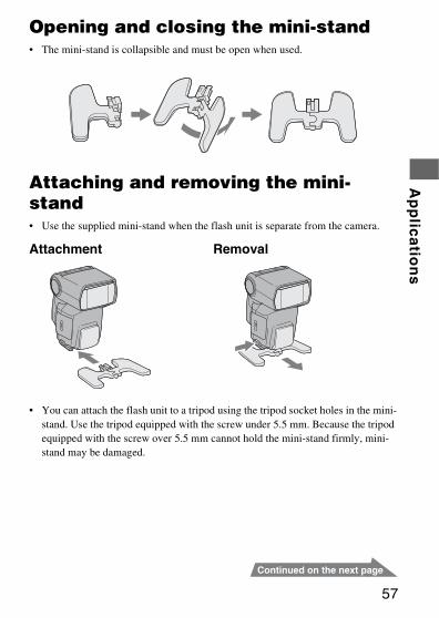
Opening and closing the mini-stand• The mini-stand is collapsible and must be open when used.
Attaching and removing the mini-stand• Use the supplied mini-stand when the flash unit is separate from the camera.
Attachment Removal
• You can attach the flash unit to a tripod using the tripod socket holes in the mini-stand. Use the tripod equipped with the screw under 5.5 mm. Because the tripod equipped with the screw over 5.5 mm cannot hold the mini-stand firmly, mini-stand may be damaged.
58
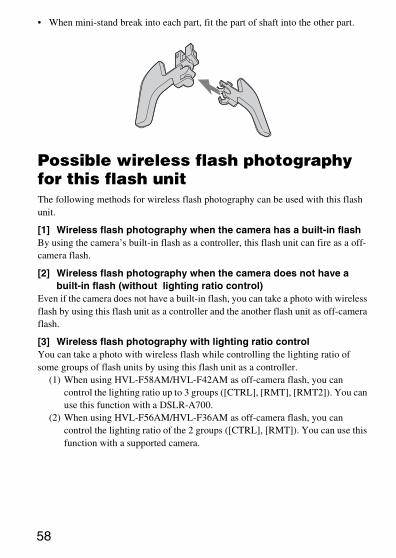
• When mini-stand break into each part, fit the part of shaft into the other part.
Possible wireless flash photography for this flash unitThe following methods for wireless flash photography can be used with this flash unit.
[1] Wireless flash photography when the camera has a built-in flashBy using the camera’s built-in flash as a controller, this flash unit can fire as a off-camera flash.
[2] Wireless flash photography when the camera does not have a built-in flash (without lighting ratio control)
Even if the camera does not have a built-in flash, you can take a photo with wireless flash by using this flash unit as a controller and the another flash unit as off-camera flash.
[3] Wireless flash photography with lighting ratio controlYou can take a photo with wireless flash while controlling the lighting ratio of some groups of flash units by using this flash unit as a controller.
(1) When using HVL-F58AM/HVL-F42AM as off-camera flash, you can control the lighting ratio up to 3 groups ([CTRL], [RMT], [RMT2]). You can use this function with a DSLR-A700.
(2) When using HVL-F56AM/HVL-F36AM as off-camera flash, you can control the lighting ratio of the 2 groups ([CTRL], [RMT]). You can use this function with a supported camera.
Ap
plic
atio
ns
59
• For details, see “Combination of camera, off-camera flash and controller.”• You can use several off-camera flashes at the same time.• In this manual, “controller” means the flash unit attached to a camera, and “off-
camera flash” means the flash unit removed from a camera for use.
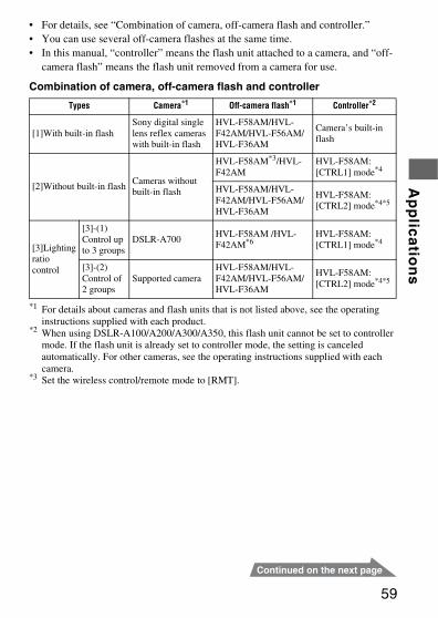
Combination of camera, off-camera flash and controller
*1 For details about cameras and flash units that is not listed above, see the operating instructions supplied with each product.
*2 When using DSLR-A100/A200/A300/A350, this flash unit cannot be set to controller mode. If the flash unit is already set to controller mode, the setting is canceled automatically. For other cameras, see the operating instructions supplied with each camera.
*3 Set the wireless control/remote mode to [RMT].
Types Camera*1 Off-camera flash*1 Controller*2
[1]With built-in flashSony digital single lens reflex cameras with built-in flash
HVL-F58AM/HVL-F42AM/HVL-F56AM/HVL-F36AM
Camera’s built-in flash
[2]Without built-in flashCameras without built-in flash
HVL-F58AM*3/HVL-F42AM
HVL-F58AM: [CTRL1] mode*4
HVL-F58AM/HVL-F42AM/HVL-F56AM/HVL-F36AM
HVL-F58AM: [CTRL2] mode*4*5
[3]Lightingratio control
[3]-(1) Control up to 3 groups
DSLR-A700HVL-F58AM /HVL-F42AM*6
HVL-F58AM: [CTRL1] mode*4
[3]-(2) Control of 2 groups
Supported cameraHVL-F58AM/HVL-F42AM/HVL-F56AM/HVL-F36AM
HVL-F58AM: [CTRL2] mode*4*5

60
*4 This flash unit has two wireless control modes, [CTRL1] and [CTRL2]. The wireless controller indicator on the LCD panel is displayed as follows.[CTRL1] mode: [CTRL+]When using HVL-F58AM/HVL-F42AM as off-camera flash, select this mode.[CTRL2] mode: [CTRL]When using HVL-F56AM/HVL-F36AM as off-camera flash, select this mode.When you change the controller mode, set [C03] in the custom setting (page 74).
*5 When using DSLR-A700, this flash unit cannot be set to [CTRL](CTRL2). If the flash unit is already set to [CTRL], the setting is canceled automatically. For other cameras, see the operating instructions supplied with each camera.
*6 HVL-F42AM used as off-camera flash is included in the [RMT] group.
Ap
plic
atio
ns
61
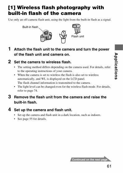
[1] Wireless flash photography with built-in flash of the cameraUse only an off-camera flash unit, using the light from the built-in flash as a signal.
1 Attach the flash unit to the camera and turn the power of the flash unit and camera on.
2 Set the camera to wireless flash.• The setting method differs depending on the camera used. For details, refer
to the operating instructions of your camera.• When the camera is set to wireless the flash is also set to wireless
automatically, and WL is displayed on the LCD panel.The flash channel information is transmitted to the camera.
• The light level can be changed even for the wireless flash mode. For details, refer to page 74.
3 Remove the flash unit from the camera and raise the built-in flash.
4 Set up the camera and flash unit.• Set up the camera and flash unit in a dark location, such as indoors.• See page 55 for details.
Built-in flash
Flash unit
62
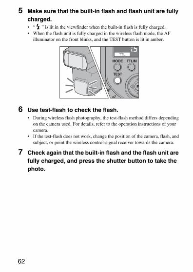
5 Make sure that the built-in flash and flash unit are fully charged.• “ ” is lit in the viewfinder when the built-in flash is fully charged.• When the flash unit is fully charged in the wireless flash mode, the AF
illuminator on the front blinks, and the TEST button is lit in amber.
6 Use test-flash to check the flash.• During wireless flash photography, the test-flash method differs depending
on the camera used. For details, refer to the operation instructions of your camera.
• If the test-flash does not work, change the position of the camera, flash, and subject, or point the wireless control-signal receiver towards the camera.
7 Check again that the built-in flash and the flash unit are fully charged, and press the shutter button to take the photo.
Ap
plic
atio
ns
63
Setting wireless flash by flash onlyOnce you have performed the wireless flash setup in step [1], if you continue to use the same camera and flash combination without changing the wireless channel then you can also set the flash and camera separately to wireless.
Camera setting:Set the camera to the wireless flash mode.For details, refer to the operating instructions supplied with your camera.
Flash setting:
1 Press the TTL/M button to display or .• When selecting , the flash unit fires with the power level to be
set.
2 Press the MODE button repeatedly to display [ WL].
3 Press the Fn button.
4 Press the g or G button to make [RMT] or [RMT2] blink.
5 Press the Fn button.• Make sure that the wireless channel of the off-camera flash is set to the
same channel as the controller. For details on setting the wireless channel, see “Custom setting” (page 74).
64
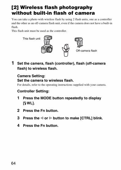
[2] Wireless flash photography without built-in flash of cameraYou can take a photo with wireless flash by using 2 flash units, one as a controller and the other as an off-camera flash unit, even if the camera does not have a built-in flash.This flash unit must be used as the controller.
1 Set the camera, flash (controller), flash (off-camera flash) to wireless flash.
Camera Setting:Set the camera to wireless flash.For details, refer to the operating instructions supplied with your camera.
Controller Setting:
1 Press the MODE button repeatedly to display [ WL].
2 Press the Fn button.
3 Press the g or G button to make [CTRL] blink.
4 Press the Fn button.
This flash unit
Off-camera flash
Ap
plic
atio
ns
65
5 Press the g or G button to make RATIO [OFF] blink.
6 Press the Fn button.• [CTRL+] or [CTRL] is displayed.
Off-camera flash setting:Set the wireless flash while the flash unit is attached to the camera, and then remove it from the camera. For details, refer to the operating instructions supplied with the external flash. When the HVL-F58AM is used as the off-camera flash, see page 63, and set the remote mode to [RMT].
2 Attach the controller to the camera, and turn on the power of the camera, controller, off-camera flash.
3 Set up the camera with the controller and the off-camera flash.• See page 55 for details.
4 Make sure that the controller and the flash unit are fully charged.• When the flash unit is fully charged in the wireless flash mode, the AF
illuminator on the front blinks, and the TEST button is lit in amber.
5 Use test-flash to check the flash.• The test-flash method differs depending on the camera used. For details,
refer to the operating instructions of your camera.• If the test-flash does not work, change the position of the camera, flash, and
subject, or point the wireless control-signal receiver towards the camera. Moreover, make sure that wireless channel of the off-camera flash is set to the same channel as the controller.
66
6 Check again that the controller and the flash unit are fully charged, and press the shutter button to take the photo.• Even if RATIO is set to [OFF], the controller flashes to transmit a signal.
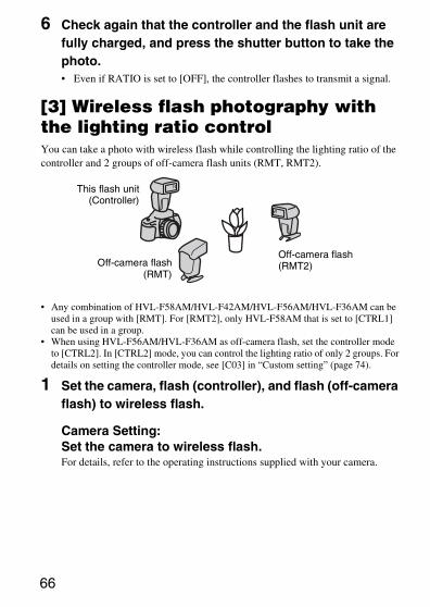
[3] Wireless flash photography with the lighting ratio controlYou can take a photo with wireless flash while controlling the lighting ratio of the controller and 2 groups of off-camera flash units (RMT, RMT2).
• Any combination of HVL-F58AM/HVL-F42AM/HVL-F56AM/HVL-F36AM can be used in a group with [RMT]. For [RMT2], only HVL-F58AM that is set to [CTRL1] can be used in a group.
• When using HVL-F56AM/HVL-F36AM as off-camera flash, set the controller mode to [CTRL2]. In [CTRL2] mode, you can control the lighting ratio of only 2 groups. For details on setting the controller mode, see [C03] in “Custom setting” (page 74).
1 Set the camera, flash (controller), and flash (off-camera flash) to wireless flash.
Camera Setting:Set the camera to wireless flash.For details, refer to the operating instructions supplied with your camera.
This flash unit(Controller)
Off-camera flash(RMT2)Off-camera flash
(RMT)
Ap
plic
atio
ns
67
Controller Setting:
1 Press the MODE button repeatedly to display [ WL].
2 Press the Fn button.
3 Press the g or G button to make [CTRL] blink.
4 Press the Fn button.
5 Press the g or G button to make RATIO [ON] blink.
6 Press the Fn button.
7 Press the f or F button to select the lighting ratio.• The lighting ratio may be set to the following.
1, 2, 4, 8, 16, --** The flash unit cannot flash when the lighting ratio is set to [--].
8 Press the g or G button to select the lighting ratio of the controller and off-camera flash units (RMT, RMT2).
9 Press the Fn button.
10 Press the TTL/M button to display .• When is selected, manual setting flash is used with the
lighting ratio control.
68
Off-camera flash setting:Set the wireless flash while the flash unit is attached to the camera, and then remove it from the camera. For details, refer to the operating instructions supplied with the external flash. When the HVL-F58AM is used as the off-camera flash, see page 63.
2 Attach the controller to the camera, and turn on the power of the camera, controller, and off-camera flash.
3 Set up the camera with the controller and the off-camera flash.• See page 55 for details.
4 Make sure that the controller and the flash unit are fully charged.• When the flash unit is fully charged in the wireless flash mode, the AF
illuminator on the front blinks, and the TEST button is lit in amber.
5 Use test-flash to check the flash.• The test-flash method differs depending on the camera used. For details,
refer the operating instructions of your camera.• If the test-flash does not work, change the position of the camera, flash and
subject, or point the wireless control-signal receiver towards the camera. Moreover, make sure that the wireless channel of the off-camera flash is set to the same channel as the controller.
6 Check again that the controller and the flash unit are fully charged, and press the shutter button to take the photo.
Ap
plic
atio
ns
69
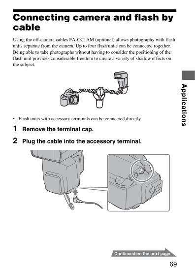
Connecting camera and flash by cableUsing the off-camera cables FA-CC1AM (optional) allows photography with flash units separate from the camera. Up to four flash units can be connected together. Being able to take photographs without having to consider the positioning of the flash unit provides considerable freedom to create a variety of shadow effects on the subject.
• Flash units with accessory terminals can be connected directly.
1 Remove the terminal cap.
2 Plug the cable into the accessory terminal.
70
• In this mode, ADI metering will be canceled and Pre-flash TTL metering will be used automatically (page 43).
• High-speed sync in the P mode cannot be used when the flash is connected with the off-camera cable FA-CC1AM (optional).
• All the flash units are at the same power level.• During photography with off-camera cable, the wireless controller mode is
canceled automatically and you cannot use the flash photography with lighting ratio control.
Ap
plic
atio
ns
71
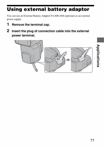
Using external battery adaptorYou can use an External Battery Adaptor FA-EB1AM (optional) as an external power supply.
1 Remove the terminal cap.
2 Insert the plug of connection cable into the external power terminal.
72
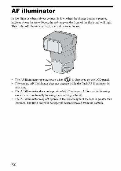
AF illuminatorIn low-light or when subject contrast is low, when the shutter button is pressed halfway down for Auto Focus, the red lamp on the front of the flash unit will light. This is the AF illuminator used as an aid in Auto Focus.
• The AF illuminator operates even when [ ] is displayed on the LCD panel.• The camera AF illuminator does not operate while the flash AF illuminator is
operating.• The AF illuminator does not operate while Continuous AF is used in focusing
mode (when continually focusing on a moving subject).• The AF illuminator may not operate if the focal length of the lens is greater than
300 mm. The flash unit will not operate when removed from the camera.
Ap
plic
atio
ns
73
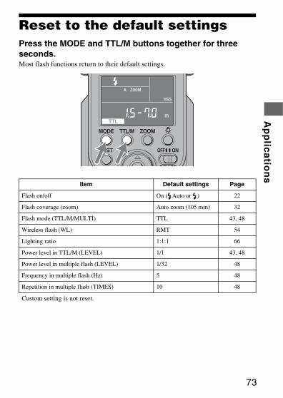
Reset to the default settingsPress the MODE and TTL/M buttons together for three seconds.Most flash functions return to their default settings.
Item Default settings Page
Flash on/off On ( Auto or ) 22
Flash coverage (zoom) Auto zoom (105 mm) 32
Flash mode (TTL/M/MULTI) TTL 43, 48
Wireless flash (WL) RMT 54
Lighting ratio 1:1:1 66
Power level in TTL/M (LEVEL) 1/1 43, 48
Power level in multiple flash (LEVEL) 1/32 48
Frequency in multiple flash (Hz) 5 48
Repetition in multiple flash (TIMES) 10 48
Custom setting is not reset.
74
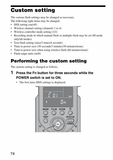
Custom settingThe various flash settings may be changed as necessary.The following eight items may be changed.• HSS setting (on/off)• Wireless channel setting (channels 1 to 4)• Wireless controller mode setting (1/2)• Recording mode in which manual flash or multiple-flash may be set (M mode
only/all modes)• Test-flash setting (once/3 times/4 seconds)• Time to power save (30 seconds/3 minutes/30 minutes/none)• Time to power save when using wireless flash (60 minutes/none)• Flash range units (m/ft)
Performing the custom settingThe custom setting is changed as follows.
1 Press the Fn button for three seconds while the POWER switch is set to ON.• The first item (HSS setting) is displayed.
Ap
plic
atio
ns
75
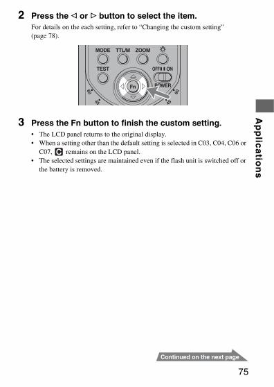
2 Press the g or G button to select the item.For details on the each setting, refer to “Changing the custom setting” (page 78).
3 Press the Fn button to finish the custom setting.• The LCD panel returns to the original display.• When a setting other than the default setting is selected in C03, C04, C06 or
C07, remains on the LCD panel.• The selected settings are maintained even if the flash unit is switched off or
the battery is removed.
76
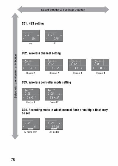
Select with the f button or F button
Sel
ect w
ith th
e g
but
ton
or G
but
ton
C01. HSS setting
on off
C02. Wireless channel setting
Channel 1 Channel 2 Channel 3 Channel 4
C03. Wireless controller mode setting
Control 1 Control 2
C04. Recording mode in which manual flash or multiple-flash may be set
M mode only All modes
Ap
plic
atio
ns
77
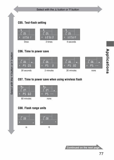
Select with the f button or F buttonS
elec
t with
the
g b
utto
n or
G b
utto
n
C05. Test-flash setting
Once 3 times
C06. Time to power save
30 seconds 3 minutes 30 minutes none
4 seconds
C07. Time to power save when using wireless flash
60 minutes none
C08. Flash range units
m ft
78
Changing the custom settingThis is an explanation of how to change each custom setting is given below.
To set the high-speed sync (C01)You can set the high-speed sync.
Press the f or F button to select [ON].• The display switches between [ON] and [OFF].• This flash unit is set to high-speed sync automatically when the shutter speed is
set faster than flash sync speed. Flash sync speed may differ depending on the camera. For further details of flash sync speed, refer to operating instructions supplied with your camera.
• Taking photos in bright locations is recommended.• High-speed sync cannot be used with bounce flash.• Using a flash meter or color meter with high-speed sync is not recommended
because it interferes with achieving the proper exposure and color.• The flash range becomes shorter than that of normal flash photography when the
high speed sync is used. Make sure that the subject is in the flash range.• You can also use the high speed sync with when using wireless flash
photography.• If you select [OFF], high-speed sync is cancelled. When high-speed sync is
cancelled, the shutter speed cannot be set faster than the sync speed.
To change the channel setting of the wireless flash (C02)You can change the wireless channel to prevent interference when another flash is used nearby.
Press the f or F button to select the desired setting.• The display is changed in the following order.
[CH-1] y [CH-2] y [CH-3] y [CH-4] y . . .• Attach the flash unit to the camera and press the shutter button partway down
after changing the channel.
Ap
plic
atio
ns
79
To select wireless control mode (C03)You can change the wireless control mode. This flash unit has two controller modes, [CTRL1] and [CTRL2]. The wireless controller indicator on the LCD panel is displayed as follows.[CTRL1] mode: [CTRL+]When using HVL-F58AM/HVL-F42AM as off-camera flash, select this mode.[CTRL2] mode: [CTRL]When using HVL-F56AM/HVL-F36AM as off-camera flash, select this mode.
Press the f or F button to select the wireless control mode.• The display switches between [CTRL1] and [CTRL2].
To change the recording mode that can use the manual flash mode (M) and multiple flash mode (C04)You can change the recording mode that can use the manual flash mode (M) and multiple flash mode.
Press the f or F button to select the recording mode that can use the manual flash mode and multiple flash mode.
• The display is changed as following.M: (corresponds M mode of the camera only)PASM: (corresponds all modes of the camera)
• When [PASM] is selected, manual flash photography and multiple flash photography may be used in all recording modes of your camera. The proper exposure may not be obtained with photography in modes other than the M mode of your camera, therefore we recommend the M mode of your camera.
80
To change the test-flash mode (C05)You can change the flashing method when using test-flash.
Press the f or F button to select the test-flash setting.• The display is changed in the following order.
[TEST1] y [TEST3] y [TESTM] y . . .[TEST1] : flashes once at the set light level.[TEST3] : flashes three times at a specific rate.[TESTM] : flashes for four seconds at a specific rate.
To change the time to power save (C06)You can change the time to power save.
Press the f or F button to select the desired time until power save.• The display is changed in the following order.
[PS 0.5] y [PS 3] y [PS 30] y [PS --] y [PS 0.5] y . . .[PS 0.5] : changes to power save mode after 30 seconds.[PS 3] : changes to power save mode after 3 minutes.[PS 30] : changes to power save mode after 30 minutes.[PS --] : disables power save mode.
To change the time to power save when using wireless flash (C07)You can change the time to power save when using wireless flash.
Press the f or F button to select the time until power save when using wireless flash.
• The display switches between [PS 60] and [PS --].[PS 60] : changes to power save mode after 60 minutes.[PS --] : disables power save mode.
To change the flash range units (C08)You can change the flash range units displayed.
Press the f or F button to select the units.• The display switches between [m] and [ft].
Ad
ditio
na
l Info
rma
tion
81
Additional Information
Notes on useWhile shooting• This flash unit generates strong light, so it should not be used directly in front of
the eyes.• Do not use the flash 20 times in a row or in quick succession in order to prevent
heating and degradation of the camera and flash unit. (when the power level is 1/32, 40 times in a row.)Stop using the flash unit and cool it for 10 minutes or more, if the flash is triggered up to the limit for the number of times in quick succession.
• Attach the camera while the flash unit is turned off.If you do not do so, you may cause a malfunction of the flash unit or the use of an incorrect luminescence, and the powerful light may damage your eyes.
• Do not use the flash near people when rotating the flashtube during bounce photography. The flash light may damage the eyes, or the hot flashtube may cause a burn.
Batteries• The battery level displayed on the LCD panel may be lower than the actual
battery capacity, due to temperature and storage conditions. The displayed battery level is restored to the correct value after the flash has been used a few times.
• Nickel-metal hydride batteries can lose power suddenly. If the low-battery indicator starts blinking or the flash can no longer be used while taking pictures, change or recharge the batteries.
• The flash frequency and number of flashes provided by new batteries may vary from the values shown in the table, depending on the time elapsed since manufacture of the batteries.
82
• Remove the batteries only after turning the power off and waiting several minutes, when changing the batteries. The batteries may be hot, depending on the battery type. Remove them carefully.
• Remove and store the batteries when you do not intend to use the camera for a long time.
Temperature• The flash unit may be used over a temperature range of 0 °C to 40 °C.• Do not expose the flash unit to extremely high temperatures (e.g. in direct
sunlight inside a vehicle) or high humidity.• To prevent condensation forming on the flash, place it in a sealed plastic bag
when bringing it from a cold environment into a warm environment. Allow it to reach room temperature before removing it from the bag.
• Battery capacity decreases at colder temperatures. Keep your camera and spare batteries in a warm inside pocket when shooting in cold weather. The low-battery indicator may blink even when there is some power left in the batteries in cold weather. Batteries will regain some of their capacity when warmed to normal operating temperature.
• This flash unit is not waterproof. Be careful not to bring it into contact with water or sand when using it at the seashore, for example. Contact with water, sand, dust, or salt may result in a malfunction.
Ad
ditio
na
l Info
rma
tion
83
MaintenanceRemove this unit from the camera. Clean the flash with a dry soft cloth. If the flash has been in contact with sand, wiping will damage the surface, and it should therefore be cleaned gently using a blower. In the event of stubborn stains, use a cloth lightly dampened with a mild detergent solution, and then wipe the unit clean with a dry soft cloth. Never use strong solvents, such as thinner or benzine, as these damage the surface finish.
84
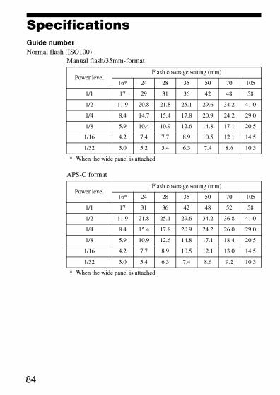
SpecificationsGuide numberNormal flash (ISO100)
Manual flash/35mm-format
APS-C format
Power levelFlash coverage setting (mm)
16* 24 28 35 50 70 105
1/1 17 29 31 36 42 48 58
1/2 11.9 20.8 21.8 25.1 29.6 34.2 41.0
1/4 8.4 14.7 15.4 17.8 20.9 24.2 29.0
1/8 5.9 10.4 10.9 12.6 14.8 17.1 20.5
1/16 4.2 7.4 7.7 8.9 10.5 12.1 14.5
1/32 3.0 5.2 5.4 6.3 7.4 8.6 10.3
* When the wide panel is attached.
Power levelFlash coverage setting (mm)
16* 24 28 35 50 70 105
1/1 17 31 36 42 48 52 58
1/2 11.9 21.8 25.1 29.6 34.2 36.8 41.0
1/4 8.4 15.4 17.8 20.9 24.2 26.0 29.0
1/8 5.9 10.9 12.6 14.8 17.1 18.4 20.5
1/16 4.2 7.7 8.9 10.5 12.1 13.0 14.5
1/32 3.0 5.4 6.3 7.4 8.6 9.2 10.3
* When the wide panel is attached.
Ad
ditio
na
l Info
rma
tion
85
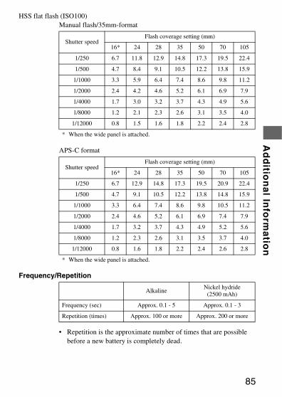
HSS flat flash (ISO100)Manual flash/35mm-format
APS-C format
Frequency/Repetition
• Repetition is the approximate number of times that are possible before a new battery is completely dead.
Shutter speedFlash coverage setting (mm)
16* 24 28 35 50 70 105
1/250 6.7 11.8 12.9 14.8 17.3 19.5 22.4
1/500 4.7 8.4 9.1 10.5 12.2 13.8 15.9
1/1000 3.3 5.9 6.4 7.4 8.6 9.8 11.2
1/2000 2.4 4.2 4.6 5.2 6.1 6.9 7.9
1/4000 1.7 3.0 3.2 3.7 4.3 4.9 5.6
1/8000 1.2 2.1 2.3 2.6 3.1 3.5 4.0
1/12000 0.8 1.5 1.6 1.8 2.2 2.4 2.8
* When the wide panel is attached.
Shutter speedFlash coverage setting (mm)
16* 24 28 35 50 70 105
1/250 6.7 12.9 14.8 17.3 19.5 20.9 22.4
1/500 4.7 9.1 10.5 12.2 13.8 14.8 15.9
1/1000 3.3 6.4 7.4 8.6 9.8 10.5 11.2
1/2000 2.4 4.6 5.2 6.1 6.9 7.4 7.9
1/4000 1.7 3.2 3.7 4.3 4.9 5.2 5.6
1/8000 1.2 2.3 2.6 3.1 3.5 3.7 4.0
1/12000 0.8 1.6 1.8 2.2 2.4 2.6 2.8
* When the wide panel is attached.
AlkalineNickel hydride
(2500 mAh)
Frequency (sec) Approx. 0.1 - 5 Approx. 0.1 - 3
Repetition (times) Approx. 100 or more Approx. 200 or more
86
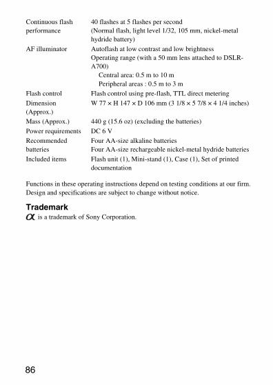
Functions in these operating instructions depend on testing conditions at our firm.Design and specifications are subject to change without notice.
Trademark is a trademark of Sony Corporation.
Continuous flash performance
40 flashes at 5 flashes per second(Normal flash, light level 1/32, 105 mm, nickel-metal hydride battery)
AF illuminator Autoflash at low contrast and low brightnessOperating range (with a 50 mm lens attached to DSLR-A700)
Central area: 0.5 m to 10 mPeripheral areas : 0.5 m to 3 m
Flash control Flash control using pre-flash, TTL direct metering
Dimension(Approx.)
W 77 × H 147 × D 106 mm (3 1/8 × 5 7/8 × 4 1/4 inches)
Mass (Approx.) 440 g (15.6 oz) (excluding the batteries)
Power requirements DC 6 V
Recommended batteries
Four AA-size alkaline batteriesFour AA-size rechargeable nickel-metal hydride batteries
Included items Flash unit (1), Mini-stand (1), Case (1), Set of printed documentation

Ad
ditio
na
l Info
rma
tion
87

Printed in Japan
Printed on 70% or more recycled paper using VOC (Volatile Organic Compound)-free vegetable oil based ink.