Embed Size (px)
Citation preview
SC-Poly-DT-O-Kit rev3 10.25.2018 © 2018. All Rights Reserved
SureCall Flare™ with Omni AntennaQuick Setup Guide
This is a CONSUMER device.
BEFORE USE, you MUST REGISTER THIS DEVICE with your wireless provider and have your provider’s consent. Most wireless providers consent to the use of signal boosters. Some providers may not consent to the use of this device on their network. If you are unsure, contact your provider.
You MUST operate this device with approved antennas and cables as specified by the manufacturer. Antennas MUST be installed at least 20 cm (8 inches) from any person.
You MUST cease operating this device immediately if requested by the FCC or licensed wireless service provider.
WARNING: E911 location information may not be provided or may be inaccurate for calls served by using this device.
This device may operate in a fixed location only, for in-building use.
This device complies with Part 15 of the FCC Rules. Operation is subject to the following two conditions: (1) this device may not cause harmful interference, and (2) this device must accept any interference received, including interference that may cause undesired operation.
3-Year Warranty Activate your three-year manufacturer warranty at www.surecall.com/activate.
SureCall warranties its products for three years from the date of purchase against defects in workmanship and/or materials.
Products returned by customers must be in their original, un-modified condition, shipped at the customer’s expense in the original or protective packaging with proof-of-purchase documentation enclosed and a Return Merchandise Authorization (RMA) number printed clearly on the outside of the shipping container. RMA numbers are obtained by contacting Customer Support.
This warranty does not apply to any product determined by SureCall to have been subjected to misuse, abuse, neglect, or mishandling that alters or damages the product’s physical or electronic properties.
For complete warranty text, including limitations and liability, see the Flare full user manual, available online at surecall.com/support
Specifications
Uplink Frequency Range (MHz): 698-716 / 776-787 / 824-849 / 1850-1915 / 1710-1755
Downlink Frequency Range (MHz): 728-746 / 746-757 / 869-894 / 1930-1995 / 2110-2155
Maximum Gain: 72 dB
Supported Standards: CDMA, WCDMA, GSM, EDGE, HSPA+, EVDO, LTE & all cellular standards`
Impedance: 75Ω / 50 Ω
Noise Figure: 7 dB
AC Input: Input: AC 110 – 240 V, 60 Hz ; Output: DC 5V / 3A
Maximum Output Power: 1 Watt EIRP
Cable: RG6
RF Connectors: Donor: F Female; Server: Integral
Power Consumption: <12W
Certifications (Flare 3.0) FCC ID: RSNFLARE-3
Best
Ant
enna
Sep
arat
ion
Best
Ant
enna
Sep
arat
ion
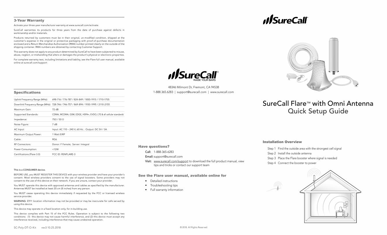
Step 1 Find the outside area with the strongest cell signal
Step 2 Install the outside antenna
Step 3 Place the Flare booster where signal is needed
Step 4 Connect the booster to power
Installation OverviewHave questions?
Call: 1-888-365-6283
Email: [email protected]
Visit: www.surecall.com/support to download the full product manual, view tips and tricks or contact our support team
See the Flare user manual, available online for • Detailed instructions • Troubleshooting tips• Full warranty information
48346 Milmont Dr, Fremont, CA 94538
1-888.365.6283 | [email protected] | www.surecall.com
SC-Poly-DT-O-Kit rev3 10.15.2018
SureCall Flare™ with Omni Antenna
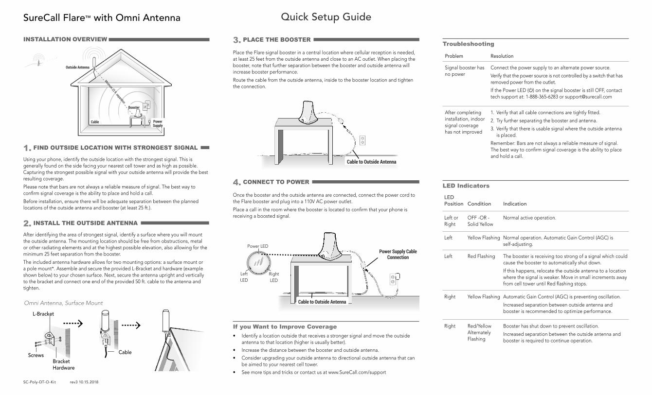
4. CONNECT TO POWER
Quick Setup Guide
Once the booster and the outside antenna are connected, connect the power cord to the Flare booster and plug into a 110V AC power outlet.
Place a call in the room where the booster is located to confirm that your phone is receiving a boosted signal.
LED Indicators
LED Position Condition Indication
Left or Right
OFF -OR - Solid Yellow
Normal active operation.
Left Yellow Flashing Normal operation. Automatic Gain Control (AGC) is self-adjusting.
Left Red Flashing The booster is receiving too strong of a signal which could cause the booster to automatically shut down.
If this happens, relocate the outside antenna to a location where the signal is weaker. Move in small increments away from cell tower until Red flashing stops.
Right Yellow Flashing Automatic Gain Control (AGC) is preventing oscillation.
Increased separation between outside antenna and booster is recommended to optimize performance.
Right Red/Yellow Alternately Flashing
Booster has shut down to prevent oscillation.
Increased separation between the outside antenna and booster is required to continue operation.
Troubleshooting
Problem Resolution
Signal booster has no power
Connect the power supply to an alternate power source.
Verify that the power source is not controlled by a switch that has removed power from the outlet.
If the Power LED (�) on the signal booster is still OFF, contact tech support at: 1-888-365-6283 or [email protected]
After completing installation, indoor signal coverage has not improved
1. Verify that all cable connections are tightly fitted.
2. Try further separating the booster and antenna.
3. Verify that there is usable signal where the outside antenna is placed.
Remember: Bars are not always a reliable measure of signal. The best way to confirm signal coverage is the ability to place and hold a call.
Omni Antenna, Surface Mount
ScrewsBracket Hardware
Cable
L-Bracket
Best
Ant
enna
Sep
arat
ion
Best
Ant
enna
Sep
arat
ion
Booster
Power Supply
Cable
Outside Antenna
Minimum 25 ft. separation
Using your phone, identify the outside location with the strongest signal. This is generally found on the side facing your nearest cell tower and as high as possible. Capturing the strongest possible signal with your outside antenna will provide the best resulting coverage.
Please note that bars are not always a reliable measure of signal. The best way to confirm signal coverage is the ability to place and hold a call.
Before installation, ensure there will be adequate separation between the planned locations of the outside antenna and booster (at least 25 ft.).
1. FIND OUTSIDE LOCATION WITH STRONGEST SIGNAL
After identifying the area of strongest signal, identify a surface where you will mount the outside antenna. The mounting location should be free from obstructions, metal or other radiating elements and at the highest possible elevation, also allowing for the minimum 25 feet separation from the booster.
The included antenna hardware allows for two mounting options: a surface mount or a pole mount*. Assemble and secure the provided L-Bracket and hardware (example shown below) to your chosen surface. Next, secure the antenna upright and vertically to the bracket and connect one end of the provided 50 ft. cable to the antenna and tighten.
2. INSTALL THE OUTSIDE ANTENNA
INSTALLATION OVERVIEW
If you Want to Improve Coverage• Identify a location outside that receives a stronger signal and move the outside
antenna to that location (higher is usually better).
• Increase the distance between the booster and outside antenna.
• Consider upgrading your outside antenna to directional outside antenna that can be aimed to your nearest cell tower.
• See more tips and tricks or contact us at www.SureCall.com/support
Best
Ant
enna
Sep
arat
ion
Best
Ant
enna
Sep
arat
ion
Cable to Outside Antenna
Power Supply Cable Connection
Left LED
Right LED
Power LED
Best
Ant
enna
Sep
arat
ion
Best
Ant
enna
Sep
arat
ion
Cable to Outside Antenna
Place the Flare signal booster in a central location where cellular reception is needed, at least 25 feet from the outside antenna and close to an AC outlet. When placing the booster, note that further separation between the booster and outside antenna will increase booster performance.
Route the cable from the outside antenna, inside to the booster location and tighten the connection.
3. PLACE THE BOOSTER