Embed Size (px)
Citation preview

FLANGED SERIES Y-STRAINERS

PPaarrttss LLiisstt aanndd SSttaannddaarrdd MMaatteerriiaallss
Y-Strainers
2
IRON PIPE FLANGED Y-STRAINERS
APOLLO® SERIES 125YF AND 250YF
Y-Strainers
FEATURES
• Iron strainers are complete with Flat Face(Series 125YF) or Raised Face (Series 250YF)flanges in accordance with ASME B16.1.
• Strainer body meets applicable ASMEStandard.
• One piece cast body.• Strainers equipped with bolted cover
flange that utilize a flat gasket seal.• Low pressure drop.
• Upper and lower machined seats.• 304 SS perforated screens are standard.• Drain/Blow-off connection furnished with
plug as standard.• Generous screen area and properly
proportioned straining chamber to minimize initial pressure drop while maximizing time between cleanings.
• Compact end to end dimension.
PPaarrtt CCaasstt IIrroonn DDuuccttiillee IIrroonnAAppoolllloo MMooddeell 112255YYFF 225500YYFFBody A126-B A395Cover A126-B A395Screen 1 304 SS 304 SSPlug 2 A126-B A126-BGasket 1 Graphite GraphiteBolt/Stud 2 A307-B A307-BNut 2 A563 A563
NNootteess:1. Recommended Spares.2. Materials of equivalent strength may be substituted at
manufacturer’s option.
UUppppeerr PPrreessssuurree LLiimmiittss ((NNoonn--SShhoocckk))AAppoolllloo MMooddeell BBooddyy MM..AA..WW..PP.. EEnnddss
MMaatteerriiaall PPSSIIGG ((BBaarrss))125YF A126-B 200 (13.79) FF(up to 12" size) Cast iron125YF A126-B 150 (10.34) FFSizes 14" and up) Cast iron250YF A395 500 (34.47) RF(Sizes 2" - 12") Ductile ironBBooddyy MMaatteerriiaall LLoowweerr LLiimmiitt °°FF ((°°CC))A126-B, A395 -20 (-28.9)
DDiimmeennssiioonnaall DDaattaa ((IIrroonn CCllaasssseess 112255,, 225500)) **uussee ccoolluummnnss ffrroomm cchhaarrtt aabboovveeAA BB CC DD EE WWeeiigghhtt
112255YYFF 225500YYFF 112255YYFF 225500YYFF 112255YYFF 225500YYFF 11225500YYFF 225500YYFF 112255YYFF 225500YYFF YY112255 YY2255002" 2.00 2.00 8.88 8.88 6.00 6.50 8.50 9.13 1/2 1/2 22 2850 51 51 226 226 152 165 216 232 15 15 10 13
21/2" 2.50 2.50 10.75 11.25 8.00 7.00 11.25 9.88 1 1 35 3865 64 64 273 289 203 178 286 251 25 25 16 173" 3.00 3.00 11.50 11.63 8.75 8.00 12.25 11.25 1 1 43 5480 76 76 292 295 222 203 311 286 25 25 20 244" 4.00 4.00 13.88 14.50 9.50 10.75 13.38 15.00 11/4 1 75 110
100 102 102 353 368 241 273 340 381 32 25 34 505" 5.00 5.00 16.38 17.38 11.50 13.50 16.13 19.00 11/4 11/4 115 160
125 127 127 416 441 292 343 410 483 32 32 52 736" 6.00 6.00 18.50 18.75 12.63 16.25 17.69 22.75 11/2 11/2 154 224
150 152 152 470 476 321 413 449 578 40 40 70 1028" 8.00 8.00 21.38 21.88 16.38 19.50 23.00 27.75 11/2 11/2 243 468
200 203 203 543 556 416 495 584 692 40 40 110 21210” 10.00 10.00 26.00 27.25 19.00 21.25 26.70 29.75 2 2 390 590250 254 254 660 692 483 540 678 756 50 50 177 26812" 12.00 12.00 30.00 31.38 22.00 25.00 31.00 35.00 2 2 650 890300 305 305 762 797 559 635 787 889 50 50 295 40414" 14.00 - 37.38 - 29.00 - 41.00 - 2 - 815 -350 356 - 949 - 737 - 1041 - 50 - 370 -16" 16.00 - 42.50 - 33.00 - 46.00 - 2 - 1224 -400 406 - 1080 - 838 - 1168 - 50 - 555 -
Customer Service 1-704-841-6000

Customer Service 1-704-841-6000 3
Engineering DataScreen Openingsfor Y-Strainers
1 /4"
Dia
. - 4
0% O
.A.
3 /16
" D
ia. -
50%
O.A
.
5 /32
" D
ia. -
58%
O.A
1 /8"
Dia
. - 4
0% O
.A.
3 /32
" D
ia. -
39%
O.A
1 /16
" D
ia. -
37%
O.A
.
3 /64
" D
ia. -
36%
O.A
.
1 /32
" D
ia. -
40%
O.A
.
0.02
7" D
ia. -
23%
O.A
.
20 M
esh
- 49
% O
.A.
0.03
5" O
peni
ngs
30 M
esh
- 45
% O
.A.
0.02
2" O
peni
ngs
40 M
esh
- 41
% O
.A.
0.01
6" O
peni
ngs
60 M
esh
- 38
% O
.A.
0.01
0" O
peni
ngs
80 M
esh
- 36
% O
.A.
0.00
8" O
peni
ngs
100
Mes
h -
30%
O.A
.0.
006"
Ope
ning
s
NNootteess::1. Screen openings other than those shown above are available.2. Screens are available in a wide range of materials, CS, SST, Alloy 20, Monel 400, Hastalloy C and Titanium GR2.3. Custom manufactured screens are available upon request. Please consult factory.4. All mesh screens include liner;
.045 Perf 3" and smaller
.125 Perf 4" and larger.
FACTORS TO CONSIDER
SCREEN TYPES/DIMENSIONS
PURPOSE
If the basket strainer is being used for protection rather than direct filtration, Apollo’s standard screens will suffice in most applications.
SERVICE
With services that require extremely sturdy screens, such as high pressure/ temperatureapplications or services with high viscosities, Apollo® recommends that perforated screenswithout mesh liners be used. If mesh is required to obtain a certain level of filtration, thenApollo recommends a trapped perf./mesh/perf. combination.
FILTRATION LEVEL
When choosing a perf. or a mesh/perf. combination attention should be given to ensureoverstraining does not occur. As a general rule the specified level of filtration should be nosmaller than half the size of the particle to be removed. If too fine a filtration is specifiedthe pressure drop through the strainer will increase very rapidly, possibly causing damageto the basket.
SSttaannddaarrdd SSccrreeeennssSSiizzee RRaannggee OOppeenniinngg2" - 3" 0.045 in.50mm - 80mm 1.2mm4" and larger 0.125 in.100mm and larger 3.2mm
Y-Strainers
Y-Strainers
Customer Service 1-704-841-60004
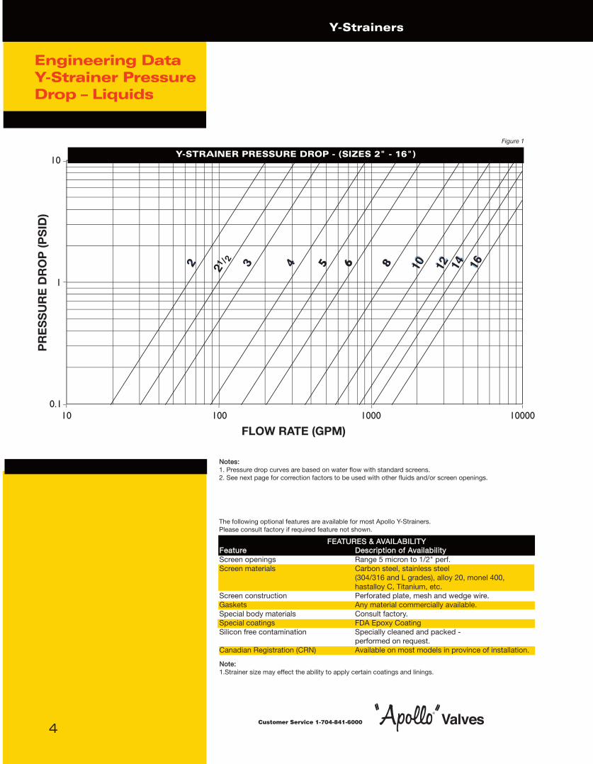
Engineering DataY-Strainer PressureDrop – Liquids
Figure 1
Y-STRAINER PRESSURE DROP - (SIZES 2" - 16")
NNootteess::1. Pressure drop curves are based on water flow with standard screens.2. See next page for correction factors to be used with other fluids and/or screen openings.
The following optional features are available for most Apollo Y-Strainers. Please consult factory if required feature not shown.
FFEEAATTUURREESS && AAVVAAIILLAABBIILLIITTYYFFeeaattuurree DDeessccrriippttiioonn ooff AAvvaaiillaabbiilliittyyScreen openings Range 5 micron to 1/2" perf.Screen materials Carbon steel, stainless steel
(304/316 and L grades), alloy 20, monel 400, hastalloy C, Titanium, etc.
Screen construction Perforated plate, mesh and wedge wire.Gaskets Any material commercially available.Special body materials Consult factory.Special coatings FDA Epoxy CoatingSilicon free contamination Specially cleaned and packed -
performed on request.Canadian Registration (CRN) Available on most models in province of installation.
NNoottee:: 1.Strainer size may effect the ability to apply certain coatings and linings.

Customer Service 1-704-841-6000 5
*Multiply values obtained from figure 1 thru 4 by the appropriate values shown below Chart #1
A) Using Figure 1 the pressure drop is determined to be 1.0 psid with Apollo’s standard screen.
B) Looking at page 3 we find that the % open area of 100 mesh is 30%.
C) Using Chart #1 we read the correction factor to be 1.2 for 100 mesh lined .045" perf.
D) Total pressure drop equals 1.0 x 1.2 = 1.2 psid clean.
EXAMPLE
Strainer Size: 2"Filtration: 100 Mesh lined
Flow rate: 65 GPMService: Water
SSiizzee SSCCRREEEENN OOPPEENNIINNGGSSRRaannggee PPeerrffoorraatteedd PPllaattee MMeesshh lliinneedd ssttaannddaarrdd ssccrreeeennss
%% SSccrreeeenn MMaatteerriiaall OOppeenn AArreeaa %% SSccrreeeenn MMaatteerriiaall OOppeenn AArreeaa6600%% 5500%% 4400%% 3300%% 2200%% 5500%% 4400%% 3300%%
2" - 16" 0.65 0.8 1 1.4 2.15 1.05 1.05 1.2
NNootteess:: 1. See page 3 for % Open Area’s of Apollo inventoried perforated plate.2. Standard screens for sizes 2” and larger is approximately a 40% open area screen media.3. All mesh screens include liner;
.045 Perf 3" and smaller
.125 Perf 4" and larger.
Engineering DataScreen Correction Factor Chart
FOR NON-STANDARD AND MESH LINED SCREENS
HOW TO USE
1. Using Figure 1 see page 4 determine the pressure drop (P1) through the strainer with water flow and standard screens.
2. If non-standard screens (i.e. 40 mesh, etc.) are being used apply factors in Chart #1 to determine corrected pressure drop (P2).
3. Multiply P1 or P2 (is used) by the specific gravity of the fluid actually flowing through the strainer to get P3.
4. Using Chart #2 multiply P3 by the appropriate Component Factor (CF) to get P4.5. Let P5 = P3 - P4.6. Multiply P4 by the appropriate Body Loss Factor (BF) in Chart #3 to get P6.7. Multiply P5 by the appropriate Screen Loss factor (PF or MF) in Chart #3 to get P7.8. Total pressure drop P8 = P6 + P7.
A) As shown in the above example, the corrected pressure drop (P2) = 1.2 psid
B) Since S.G. = 1, P3 = P2 = 1.2 psidC) Using Chart #2 P4 = 0.35 x P3 = 0.42 psidD) P5 = 1.2 - 0.4 = 0.8 psidE) Using Chart #3 P6 = 0.4 x 1.2 = 0.48 psidF) Again using Chart #3 P7 = 0.8 x 2.5 = 2.0 psidG) Total pressure drop P8 = 0.48 + 2.0 = 2.48 psid
EXAMPLE
Strainer Size: 2"Filtration: 100 Mesh lined Flow rate: 65 GPMSpecific Gravity: 1Viscosity: 25 cP
Chart #2
VISCOSITY AND DENSITY CORRECTION FACTOR CHART
SSiizzee CCoommppoonneennttRRaannggee FFaaccttoorr
((CCFF))2" - 16” 0.35
VViissccoossiittyy BBooddyy LLoossss SSccrreeeenn LLoossss FFaaccttoorrCCpp FFaaccttoorr PPeerrff aalloonnee 2200 MMeesshh 3300,, 4400,, MMeesshh 6600 ttoo 330000 MMeesshh
((BBFF)) ((PPFF)) LLiinneedd ((MMFF)) LLiinneedd ((MMFF)) LLiinneedd ((MMFF))10 1 1.15 1.3 1.4 1.525 1.2 1.25 2 2.2 2.5100 1.6 1.4 3 4 6.5200 2.2 1.5 4.5 7 11.5500 4.4 1.6 10 15 251000 8 1.7 15 30 502000 15.2 1.9 30 60 100
Chart #3
Y-Strainers

Y-Strainers
Customer Service 1-704-841-60006
EXAMPLE
Service: Saturated Steam FlowPressure: 400 psigSteam Flow: 90,000 Lbs/hrSize: 8"
• Locate steam flow.• Follow horizontal line to required pressure.• Follow vertical line downwards to required strainer size.• Follow horizontal line to read pressure drop.• Pressure drop equals 2.0 psid.
Engineering DataY-Strainer Pressure Drop – Saturated Steam
WHERE
Qs = Equivalent Steam Flow, lbs./hr.
Qg = Air or gas flow, SCFM.
t = Temperature, °F.
s.g. = Specific gravity (s.g. = 1 for air.)
DP = Pressure Drop, psid
P2 = Outlet Pressure
NNootteess:: 1. Pressure drop curve is based on saturated steam flow with standard screens. See page 5 for correction
factors to be used with other screen openings.2. Chart can be used for air and gas by using the following formula:
SIZES 2" - 16"
Qs = 0.138 Qg

Customer Service 1-704-841-6000 7
The strainer shall be a Y-Type and have
(size) inlet/outlet connections. The end connections shall be
flanged and the body shall be complete with a bolted cover assembly.
The strainer shall be suitable for PSIG operating
pressure at °F operating temperature. The body shall
be constructed of (body material)
while the screen shall be constructed of
(screen material). A mesh lining
of (size of mesh) is required,
allowing a maximum pressure drop of psig.
The strainer shall be equipped with a (gasket material)
gasket and the strainer screen shall be able to withstand
psig differential pressure without
any deformation.
Strainers shall be Apollo Model #
or approved equivalent.
Name
Company
Address
City/Town
State Zip Code
Telephone ( )
Fax ( )
STRAINER CHECK LIST
When selecting a strainer, please take the factors listed below into account. This will assist us when recommending a strainer to suit your specific requirements. Please photocopy this page and fill out the pertinent information.
1. Fluid to be strained
2. Flow rate
3. Density of fluid
4. Viscosity of fluid
5. Fluid working pressure
Maximum pressure
6. Fluid working temp.
Maximum temp.
7. Preferred material of strainer construction
8. Present pipeline size & material
9. Nature of solids to be strained out
10. Size of solids to be strained out
Size of mesh or perf. req.
11. Clearance Limitation Above Below
Left side facing inlet Right side facing inlet
12. Maximum pressure drop with clean screen
13. Expected cleaning frequency
14. Any other information deemed relevant
SUGGESTED SPECIFICATIONS
Check List and Suggested Specifications
Y-Strainers

Y-Strainers
Customer Service 1-704-841-60008
Installation andMaintenanceInstructions
1.0 STRAINER INSTALLATION INSTRUCTIONS
A. Ensure all machined surfaces are free of defects and that the inside of thestrainer is free of foreign objects.
B. For horizontal pipelines, the strainer should be installed so that the drainconnection is pointed downwards.
C. For flanged end strainers, the flange bolting should be tightened gradually ina back and forth clockwise motion.
D. Once installed, increase line pressure gradually and check for leakage around joints.
E. If the strainer is supplied with a start-up screen, monitor pressure drop carefully.
NOTE: Flat face mating flanges and full face gaskets must be used with 125YF series strainers toavoid damage to the cast iron body.
IMPORTANT
Ultimate responsibility for strainer and material selection rests with thecustomer, as only the customer knows the particular use to which the strainerwill be put and the exact operating parameters to which it will be subjected.
2.0 STRAINER REMOVAL INSTRUCTIONS
A. Drain piping.
B. Vent line to relieve pressure.
C. Secure necessary lifting equipment to strainer assembly.
D. Loosen flange bolts (Pipe flanges only).
E. Remove inlet/outlet flange bolts and carefully remove strainer.
CCAAUUTTIIOONN SSHHOOUULLDD BBEE TTAAKKEENN DDUUEE TTOO PPOOSSSSIIBBLLEE EEMMIISSSSIIOONN OOFF PPRROOCCEESSSSMMAATTEERRIIAALL FFRROOMM PPIIPPIINNGG.. AALLWWAAYYSS EENNSSUURREE NNOO LLIINNEE PPRREESSSSUURREE EEXXIISSTTSSWWHHEENN OOPPEENNIINNGG CCOOVVEERR..
3.0 MAINTENANCE INSTRUCTIONS
For maximum efficiency, determine the length of time it takes for the pressure drop todouble that in the clean condition. Once the pressure drop reaches an unacceptablevalue, shut down line and follow the “Screen Replacement Instructions”. A pressuregauge installed before and after the strainer in-line will indicate pressure loss due toclogging and may be used to determine when cleaning is required.
4.0 SCREEN REPLACEMENT
It is recommend that the system and strainer be depressurized beforeattempting any repair work. After removing all pressure, the system should bedrained, any connections to the blow-off plug should be removed, and thefollowing procedure should be used to replace the screen.
A. Attach cable or chain to strainer cover (1) and apply sufficient tension toprevent cover from dropping.
B. Remove bolts from cover.
C. Remove cover, clean and inspect gasket surface of cover.
D. Remove and discard old gasket.
E. Remove and clean or discard old screen.

Customer Service 1-704-841-6000 9
Engineering DataY-Strainer EffectiveScreen Area
NNoommiinnaall GGrroossss RRaattiiooSSttdd.. AArreeaa ooff SSccrreeeenn FFrreeee FFrreeee AArreeaa
PPiippee OOppeenniinngg PPiippee FFiittttiinngg AArreeaa AArreeaa ttoo PPiippeeSSeerriieess SSiizzee ((IInn..)) ((iinn..)) ((SSqq.. IInn..)) ((SSqq.. IInn..)) ((SSqq.. IInn..)) AArreeaa
112255YYFF 2 0.045 3.14 30.07 10.82 3.45112255YYFF 21/2 0.045 4.91 44.33 15.96 3.25112255YYFF 3 0.045 7.07 56.45 20.32 2.88112255YYFF 4 0.125 12.57 98.91 39.56 3.15112255YYFF 5 0.125 19.63 147.11 58.85 3.00112255YYFF 6 0.125 28.27 179.19 71.68 2.54112255YYFF 8 0.125 50.27 334.38 133.75 2.66112255YYFF 10 0.125 78.54 505.21 202.08 2.57112255YYFF 12 0.125 113.10 665.77 266.31 2.35112255YYFF 14 0.125 137.89 1186.34 474.54 3.44112255YYFF 16 0.125 182.65 1446.85 578.74 3.17
225500YYFF 2 0.045 3.14 35.64 12.83 4.08225500YYFF 21/2 0.045 4.91 44.33 15.96 3.25225500YYFF 3 0.045 7.07 56.45 20.32 2.88225500YYFF 4 0.125 12.57 98.91 39.56 3.15225500YYFF 5 0.125 19.63 147.11 58.85 3.00225500YYFF 6 0.125 28.27 197.92 79.17 2.80225500YYFF 8 0.125 50.27 420.97 168.39 3.35225500YYFF 10 0.125 78.54 645.99 258.40 3.29225500YYFF 12 0.125 113.10 876.70 350.68 3.10225500YYFF 14 0.125 137.89 1186.34 474.54 3.44
NNootteess::1. Values shown are for strainers with standard screens.2. Ratio Free Area to Pipe Area may be increased by changing perf. stagger or by using mesh.3. In many cases the specified screen burst pressure limits the maximum value for the Ratio Free Area to Pipe Area.
PPrreessssuurree TTeemmppeerraattuurree CChhaarrtt ((iinn aaccccoorrddaannccee wwiitthh AASSMMEEBB1166..11 aanndd AASSMMEEBB1166..3344))
Installation andMaintenanceInstructions(continued)
F. Clean and inspect gasket surface of body. If gasket surface of cover or bodyis damaged, the damaged component must be replaced.
G.Push clean screen into position in body.
H. Position new gasket in place on body.
I. Line up screen and put cover in place on body.
J. Be sure gasket, bolt holes, and screen are properly aligned.
K. Put in bolts and nuts as required
L. Tighten bolts, using “star” pattern to prevent damaging parts. Alternatetightening 180° apart. Tighten bolts sufficiently to stop leakage under testand service conditions.
Y-Strainers

XXXXXXXXXX
How To Order
Customer Service 1-704-841-600010
Apollo Flanged Y-Strainer OrderSchematic
XMODEL125Y (Flat Face)250Y (Raised Face)
SCREEN TYPE20 Mesh = M2040 Mesh = M4060 Mesh = M6080 Mesh = M80100 Mesh = M100.045 Perf = P045.062 Perf = P062.125 Perf = P125.250 Perf = P250
Y - -VALVE TYPECONNECTION/SIZEFlanged 2" = F02Flanged 2.5" = F25Flanged 3" = F03Flanged 4" = F04Flanged 5" = F05Flanged 6" = F06Flanged 8" = F08Flanged 10" = F10Flanged 12" = F12Flanged 14" = F14Flanged 16" = F16
-COATINGBlank Standard No
CoatingE Epoxy Coating,
FDA Approved
NNootteess:: *All mesh screens are reinforced with a perforated liner.2" - 3": .045 Perf4" - Larger: .125 Perf
Customer Service 1-704-841-6000 11
Terms and Condition of SalePayment: 2% 10th prox. Net 30 days. All prices F.O.B. Matthews, N.C., or Pageland, S.C.,with freight allowed on shipments of 750 pounds or $4,000 net and over to all shippingpoints within the United States excluding Alaska and Hawaii. No freight allowed on AirFreight or Parcel Post shipments. Claims for shortages must be made within 10 days ofreceipt of material. Our responsibility ends when a receipt is furnished us by the carrier.
No Invoice Rendered For Less Than $50.00. No freight will be allowed on Air Freight, AirExpress, Parcel Post or U.P.S. shipments.Other Conbraco Products may be combined tomake sufficient weight for full freight allowance. Phone order quoted prices are subject tocorrection. Prices and designs are subject to change without notice. Orders for materialor special design or specification are made to customer’s order and are not subject tocancellation or return. Goods returned to us will not be accepted unless a full explanationhas been made and our written authorized permission obtained. All goods returned – ifaccepted – will be credited at invoice price, less 30% for service and rehandling charges,plus shipping expenses.We reserve the right to adjust orders to box quantities.
Warranty and Limitations of LiabilityConbraco Industries, Inc. warrants, to its initial purchaser only, that its products which aredelivered to this initial purchaser will be of the kind described in the order or price list andwill be free of defects in workmanship or material for a period of one year from the date of delivery to you, our initial purchaser.
Should any failure to conform to this warranty appear within one year after the date of theinitial delivery to our initial purchaser, Conbraco will, upon written notification thereof andsubstantiation that the goods have been stored, installed, maintained and operated inaccordance with Conbraco's recommendations and standard industry practice, correctsuch defects by suitable repair or replacement at Conbraco's own expense.
THIS WARRANTY IS EXCLUSIVE AND IS IN LIEU OF ANY IMPLIED WARRANTY OF MER-CHANTABILITY, FITNESS FOR A PARTICULAR PURPOSE OR OTHER WARRANTY,WHETHER EXPRESS OR IMPLIED, EXCEPT THE WARRANTY OF TITLE AND AGAINSTPATENT INFRINGEMENT. Correction of non-conformities, in the manner and for the periodof time provided above, shall constitute fulfillment of all liabilities of Conbraco to our initialpurchaser, with respect to the goods, whether based on contract, negligence, strict tortor otherwise. It is the intention of Conbraco Industries, Inc. that no warranty of anykind, whether express or implied shall pass through our initial purchaser to any otherperson or corporation.
LIMITATION OF LIABILITY: Conbraco Industries, Inc. SHALL NOT UNDER ANY CIRCUM-STANCES BE LIABLE FOR SPECIAL OR CONSEQUENTIAL DAMAGES SUCH AS, BUTNOT LIMITED TO, DAMAGE TO LOSS OF OTHER PROPERTY OR EQUIPMENT, LOSS OFPROFITS OR REVENUE, COST OF CAPITAL, COST OF PURCHASED OR REPLACE-MENT GOODS, OR CLAIMS OF CUSTOMERS OF OUR INITIAL PURCHASER. THEREMEDIES OF OUR INITIAL PURCHASER, AND ALL OTHERS, SET FORTH HEREIN,ARE EXCLUSIVE, AND THE LIABILITY OF CONBRACO WITH RESPECT TO SAME SHALLNOT, EXCEPT AS EXPRESSLY PROVIDED HEREIN, EXCEED THE PRICE OF THE CON-BRACO GOODS UPON WHICH SUCH LIABILITY IS BASED.
Terms andConditions
Terms and Conditions

Conway, SC • Matthews, NC • Pageland, SC • Customer Service 1-704-841-6000 • www.conbraco.com
Printed in USA • Copyright 2006
FFoorr RReepprreesseennttaattiivveess AAnndd DDiissttrriibbuuttoorrss IInn YYoouurr IInntteerrnnaattiioonnaall AArreeaaPPlleeaassee CCoonnttaacctt TThhee CClloosseesstt CCoonnbbrraaccoo IInndduussttrriieess IInntteerrnnaattiioonnaall OOffffiiccee..
SALES AND SERVICE DEPARTMENTPO Box 247 • Matthews, NC 28106
Phone: 704-841-6000 • Fax: 704-841-6020
Sout
heas
tRe
gion
Mid
wes
tern
Reg
ion
Wes
tern
Reg
ion
North
east
Re
gion
South
ern
Regio
nCa
nada
Int’l
./
E-Mail Address Phone Fax
B. Lynch & Associates Florida [email protected] 813-792-5060 813-792-5213Spotswood Associates Georgia/Alabama [email protected] 770-447-1227 770-263-6899Pro Marketing, Inc. North Carolina/South Carolina/Tennessee-East [email protected] 864-578-4334 864-578-4889Mid South Marketing, Inc. Virginia/Maryland/Washington, D.C./WV-East [email protected] 804-213-3801 804-213-3802
Southern Marketing Group MS/TN-West/AR/Bowie Cty.-TX [email protected] 901-547-0042 901-547-0035AVC Mechanical Sales, Inc. Oklahoma/Texas-North [email protected] 214-201-0100 214-201-0104Armstrong/Weatherly Associates Texas-South/Louisiana [email protected] 713-692-5566 713-692-6021
HEBCO, Inc. Kansas/Missouri-West [email protected] 913-491-0797 913-491-5126New Tech Marketing IL/WI-East/IN-North/MI-Upper Peninsula/IA-/River Counties [email protected] 630-378-4300 630-378-0343New Tech Marketing Eastern Missouri/Southern Illinois [email protected] 618-394-0329 618-394-0427
Kentucky/Indiana-South/Ohio-South [email protected] 502-459-4545 502-459-9944V.E. Sales Co., Inc. Michigan (Except Upper Peninsula) [email protected] 586-774-7760 586-774-1490Northstar Valve & Fitting, Inc. Minnesota/North & South Dakota/Wisconisn-West [email protected] 952-937-0108 952-937-0803WilIco, Inc. Nebraska/Iowa (Except River Counties) [email protected] 402-573-7000 402-573-7371Midwest Spec Ohio-North/Pennsylvania-West/West Virginia-West [email protected] 330-538-0406 330-538-0410
Specified Process Equipment California-North [email protected] 707-553-1077 707-553-1194Cisco Speciality Products, Inc. California-South [email protected] 714-921-9228 714-921-0442SPEC Management Hawaii (S. California; Irrigation only) [email protected] 949-481-4225 949-487-0990Marshall-Rodeno Associated [email protected] 303-575-6701 303-575-6706Braley-Gray & Associates Oregon/SW Washington/Western Idaho [email protected] 503-249-6972 503-288-4464Commercial Application Sales Alaska/Washington [email protected] 206-405-4370 206-405-4390Southwestern Industrial Sales Co. Arizona/Nevada-SW [email protected] 480-458-5838 480-458-5843
Urell, Inc. Massachusetts/New England States [email protected] 617-923-9500 617-926-9414McMahon Marketing, Inc. New York-Upstate/New York-West [email protected] 518-792-3350 518-792-3351Continuous Sales Corporation New York-East/New Jersey-North [email protected] 516-575-6800 516-349-8411
[email protected] 610-485-2828 610-485-7171Keith Engle & Associates OEM accounts [email protected] 610-827-9560 610-827-9561
Conbraco Industries, Canada 160 Pennsylvania Ave., Unit 3, Concord, Ontario L4K 4A9 [email protected] 905-761-6161 905-761-6666Barclay Sales Ltd. British Columbia [email protected] 604-945-1010 604-945-3030Dynamic Agencies, Ltd. Saskatchewan [email protected] 306-343-1901 306-343-1901Tom Beggs Agencies Ltd. Manitoba/NW Ontario [email protected] 204-953-1900 204-774-6915Task Controls, Inc. Ontario [email protected] 416-291-3004 416-754-3481Agences J. Pierre Sylvain, Inc. Quebec [email protected] 450-655-9588 450-641-2737Kern Industries, Ltd. Alberta-North [email protected] 780-451-2056 780-454-6687Kern Industries Calgary, Ltd. Alberta-South [email protected] 403-730-7791 403-239-8179J. Levandier Sales, Inc. Nova Scotia, New Brunswick, Prince Edward Island [email protected] 506-858-1615 506-858-1084Smith Agencies Newfoundland [email protected] 709-364-8856 709-747-9414Key to the North Sales Agency, Inc. Ontario-North [email protected] 705-524-6714 705-566-0148Steam and Industrial Equipment Ottawa [email protected] 1-800-363-8482 514-457-7111
Rafael Rodriguez Barril, Inc. Puerto Rico [email protected] 787-982-1550 787-982-1570Conbraco International Limited Manchester, England [email protected] 44-161-212-3745 +44-161-212-3747
DKG 5M
L.J. Whitfill & Associates, Inc.
FSCA9000 • 11/06
CO/WY/MT/ID-SE/UT/NV-NE/NM/El Paso-TX
Pennsylvania-East/Delaware/New Jersey-SouthCope-Wardell-Ammon Associates
Puer
to R
ico