Embed Size (px)
Citation preview
FLAME STRAIGHTENING QUENCHED .AND -TEMPERED STEELS IN SHIP CONSTRUCTION
This document has been approvedfor public release and sale; its
distribution is unlimited.
SHIP STRUCTURE COMMITTEE
1974
—.
MEMBER AGENCIES:
LJNITED STATES COAST GUARDNAVAL stilp SYSTEMS COMMAND
Mll ITARY SEALIFT COMMAND
MARITIME ADMINISTRATION
AMERICAN BUREAU OF SHIPPING
SHIP STRUCTURE COMMI~EEAN INTERAGENCY ADVISORY
COMMITTEE DEDICATED TO IMPROVINGTHE STRUCTURE OF SHIPS
ADDRESS CORRESPONDENCE TO:
SECRETARY
SHIP STRUCTURE COMMITTEEU.S. COAST GUARD HEADQUARTERSWASHINGTON. D.C. 20590
sR-212
~ rim1974
From a previous Ship Structure Committee sponsored laboratoryinvestigation, guidelines evolved for flame straightening distortedweldments in shipyards. Validating these guidelines required thecooperation and some financial support from a shipyard to reproduce andrevise the procedures for shipyard use.
The Ship Structure Committee was fortunate to be able to joinwith Avondale Shipyards, Incorporated, to undertake this task and toreport the results in this document.
Comments on this report and suggestions for additionalresearch topics will be most welcome.
W; M. BenkertRear Admiral, U.S. Coas’cGuardChairman, Ship Structure Committee
SSC-247
FINAL TECHNICAL REPORT
on
Project SR-212, “Shipyard FormingParameter Study”
FLAME STRAIGHTENING QUENCHED-AND-
TEMPERED STEELS IN SHIP CONSTRUCTION
by
R. L. Rothman
Battelle Memorial Institute
under
Department of the PiavyNaval Ship Engineering CenterContract No. NOO(124-73-C-5173
This doewnent has been approved for public release andsale; its distribution is un2imited.
U. S. Coast Guard HeadquartersWashington, D.C.
1973
——— ... ,_ —. - -——-. -- - .—--—- ._i-—.-r- - - . . .. Lz,—
Conclusions From Shipyard Work. . . . . . . . , . . . . . . . . . 13
ACKNOWLEDGEMENTS. . . . . . . . . . . . . . . . . . . . . . . . . . . . . . 13
ABSTRACT
Flame straightening quenched–and-tempered steel procedureswere successfully employed by trained shipyard personnel on portionsof a LASH (Lighter _Woard ship) ship under construction with minimalacceptable loss in mechanical properties and with considerable savingsin time and money. Test checks were conducted in the laboratory with
simulated experiments on steel panels 150 inches by 48 inches by 5/16inch and stiffened by angles at 30-inch intervals. As much as 2 inches
of unfairness of the plating were effectively removed. A recommended
procedure is presented.
TABLE OF CONTENTS
EsiE
.. —-- ------ -..lN’LJSUIJUC’.L’IU N.... . . . . . . . . . . . . .
RECOMMENDED PROCEDURE FOR FLAME STRAIGHTENING
Thickness. . . . . . . .Equipment. . . . . . . .Temperature Measurement.Preparation. . .Straightening. .Sequence . . . .
BACKGROUND. . . . . . . . . . .
SIMULATION EXPERIMENTS. . . . .
Simulation Procedures
Simulation Results. .
.
.
.
.
.
.
.
.
.
.
.
.
.
.
.
.
.
.
.
.
.
.
.
.
.
.
.
.
.
.
.
.
.
.
.
.
.
.
.
.
.
.
.
.
.
.
.
.
.
.
.
.
.
.
.
.
.
.
. . . . . . . . . . .
QUENCHED-AND-TEMPERED
.
.
.
.
.
.
.
.
.
.
.
.
.
.
.
.
.
.
.
.
Simulation Conclusions and SignificanceSubsequent Work . . . . . . .
LABORATORY PANEL EXPERIMENTS. . . . . . .
Laboratory Panel Procedures . .
Conclusions of Laboratory Panel
SHIPYARD STRAIGHTENING. . . . . . . . . .
Properties. . . . . . . . . . .
Cost Savings. . . . . . . . . .
Conclusions From Shipyard Work.
ACKNOWLEDGEMENTS. . . . . . . . . . . . .
. . . .
. . . .
. . . .
Work. .
. . . .
. . . .
. . . .
. . . .
. . . .
.
.
.
.
.
.
.
.
.
.
.
.
.
.
.
.
.
.
.
.
to. .
. .
. .
. .
. .
. .
. .
. .
. .
.
.
.
.
.
.
.
.
.
.
.
.
.
.
.
.
.
.
.
.
.
.
.
.
.
.
.
.
.
.
.
.
.
.
.
.
.
.
.
.
.
.
.
.
.
.
.
.
.
.
.
.
.
.
.
.
.
.
.
.
.
.
.
.
.
.
.
.
.
.
.
.
.
.
.
.
.
.
.
.
.
.
.
.
.
.
.
.
.
.
.
.
.
.
.
.
.
.
.
.
.
.
.
.
.
.
.
.
.
.
.
.
.
.
.
.
.
.
.
.
.
.
.
.
.
.
.
.
.
.
.
.
.
. . .
STEEL
.
.
.
.
.
.
.
.
.
.
.
.
.
.
.
.
.
.
.
.
.
.
.
.
.
.
.
.
.
.
.
.
.
.
.
.
.
.
.
.
.
.
.
.
.
.
.
.
.
.
.
.
.
.
.
.
.
.
.
.
.
.
.
.
.
.
.
.
.
.
.
.
.
.
.
.
.
.
1
1
122222
3
4
4
5
5
5
7
10
10
11
11
13
13
-iii-
NO.—
1
2
3
NO.
LIST OF FIGURES
TEST PANEL
PANEL CONTOUR SHOWING EFFECTS OF FLAME STRAIGHTENING
FLAME STRAIGHTENING THE LASH PANEL AT AVONDALE
LIST OF TABLES
I RESULTS OF FLAME STRAIGHTENING SIMULATIONS ON QTCMODIFIED STEEL
II. PROPERTIES OF STEEL STRAIGHTENED IN THE SHIPYARD
PAGE
6
9
9
PAGE
6
12
-iv-
SHIP STRUCTURE COMMITTEE
The SHIP STRUCTURE COMMITTEE is constituted to prosecute.a researchprogram to improve the hull structures of ships by an extension of knowledgepertaining to design, materials and methods of fabrication,
RADM W. M. Benkert, USCGChief, Office of Merchant Marine Safety
U.S. Coast Guard Headquarters
CAPT J. E. Rasmussen, USN Mr. M. PitkinHead, Ship Systems Engineering Asst. Administrator for
and Design Department Commercial DevelopmentNaval Ship Engineering Center Maritime AdministrationNaval Ship Systems Command
Mr. K. Morland CAPT L. L. Jackson, USNVice President Maintenance and Repair OfficerAmerican Bureau of Shipping Military Sealift Command
SHIP STRUCTURE SUBCOMMITTEE
The SHIP STRUCTURE SUBCOMMITTEEon technical matters by providing technicalof goals and objectives of the program, andresults in terms of ship structural design,
NAVAL SHIP SYSTEMS COMMAND
Mr. P. M. Palermo - MemberMr. J. B. O’Brien - Contract AdininistratorMr. G. Sorkin - Member
U.S. COAST GUARD
LCDR E. A, Chazal - SecretaryCAPT D. J. Linde - MemberLCDR D. L, Folsom - MemberCDR W. M. Devlin - Member
MARITIME ADMINISTRATION
Mr. J. L!achtsheim - ChairmanMr. F. Dashnaw - MemberMr. F. Seibold - MemberMr. R. K. Kiss - Member
MILITARY SEALIFT COMMAND
Mr. T. W. Chapman - MemberMr. A. B. Stavovy - )lemberMr. J. G, Tuttle - Member
NATIONAL ACADEMY OF SCIENCESSHIP RESEARCH COMMITTEE
Mr. R. W. Rumke - LiaisonProf. J. E. Goldberg - Liaison
-v-
acts for the Ship Structure Committeecoordination for the determinationby evaluating and interpreting theconstruction and operation.
AMERICAN BUREAU OF SHIPPING
Mr. S. G. Stiansen - MemberNW. I. L. Stern - Member
SOCIETY OF NAVAL ARCHITECTS & MARINEENGINEERS
Mr. A. B. Stavovy - Liaison
WELDING RESEARCH COUNCIL
Mr. K. H, Koopman - Liaison
INTERNATIONAL SHIP STRUCTURES CONGRESS
Prof. J. H. Evans - Liaison
Us.
CAPT
U.S.
CAPT
Us.
COAST GUARD ACADEMY
C. R. Thompson - Liaison
MERCHANT MARINE
W. M. Maclean -
NAVAL ACADEMY
Dr. R. Bhattacharyya
ACADEMY
Liaison
- Liaison
—.-—. —...—.- — —.— . -. —- “—

NOTES
INTRODUCTION
Traditionally, shipyards have relied on flame straightening
to remove weld distortion in the case of hot-rolled steels. These steelsare very forgiving in that accidental overheating does not damage thematerial easily. The more recent interest in the use of quenched-and-
tempered steels for ship structures has posed new questions on whetherflame straightening may still be used. The basis for these questions
lies in the fact that the quenched-and-tempered steels derive theirsuperior mechanical properties from heat treatment, and further heatingcan cause deleterious effects in strength and toughness.
Investigations have been sponsored by the Ship Structure Committeeto evaluate the effect of flame straightening on the mechanical propertiesof quenched-and-tempered steel and a tentative procedure has been drawn up.By controlling the heating conditions to limit the surface temperature toa maximum of 1050 F, no significant reduction in strength and toughness isto be expected. Within this temperature limitation considerable straighten-
ing can be achieved. The following recommended procedure has been used in
the shipyard on portions of a LASH ship under construction to remove distor-tions of up to 3/8-inch bow in a portion of the structure consisting of5/16-inch stiffened panels 150 inches by 48 inches.
RECOMMENDED PROCEDURE FOR FLAME STRAIGHTENINGQUENCHED-AND-TEMPERED STEEL
Heating should be done on the high side of the plate and at
the location of maximum height. In the case of stiffened panels, this
most frequently corresponds to the reverse side of the plate from thestiffener weld.
Since the principal cause of distortion is welding, the generaloutline of the distorted regions tends to be parallel to welds. Line
heating is most effective in flame straightening this distortion. spot
heating is also useful in certain situations and is conducted under thesame general conditions as line heating.
Thickness
Flame straightening of quenched-and-tempered steels has beenconducted on 5/16-inch and l/2-inch plate. In principle, it can be
performed on any thickness plate althougha problem for very thin plates, and platefactor for thick ones.
Equipment
temperature control will bestiffness will become a major
The heating torch can vary depending on operator preferenceas can the fuel gas. The water quench should be coupled to the torchfor ease of handling. Either an annular or single stream quench canbe used.
Temperature Measurement
Temperature-indicating crayons melting at 900 F and 1050 Fshould be mounted in a single holder so that bothtaneously to the heated surface. The temperatureimmediately after removal of the flame and in theheating after
Preparation
Thestraightening
approximately 12 inches of travel.
can be applied simul-should be checkedlocation of last
preparation required is identical to that followed in flamehot-rolled steels. Initially, make an estimate of the un-
fairness and decide which panels have the greatest distortion and whichare acceptable as is. Select the high regions and mark lines along themaxima so they can be followed easily by the torch operator.
Straightening
Heat the lines marked previously maintaining a continuousquench behind the torch. Torch speed should typically be 24 to 30inches per minute; however, this will vary with such factors as the
torch, gas flow, and plate thickness. The important criterion is
temperature, and this should be checked periodically by removing thetorch and applying the temperature-indicating crayons simultaneouslyand quickly. The 900 F crayon should melt, but the 1050 F one should
not. As an additional check on temperature, no obvious color shouldbe visible immediately after removing the torch. Such choices as
whether to work upwards or downwards on a bulkhead will depend onthe particular equipment being used and should be made by the operator.
Sequence
Heat the lines with greatest distortion first using onepass per line. Then, check the unfairness and proceed to the less
-2-
distorted lineslif necessarY. If further straightening is required
after completing one pass per line, heat additional lines approximately
one inch to the side of the initial lines.
BACKGROUND
This program was undertaken to complete the laboratory develop-
ment of flame-straightening techniques for quenched-and-tempered steelsand to demonstrate its success in the shipyard.
For years, shipyards have relied on flame straightening to
remove the welding distortion introduced during fabrication in thecase of hot-rolled steels. These steels are relatively forgiving with
regard to flame-straightening temperatures and consequently the processcan be applied to them at the discretion of the yard. Quenched-and-
tempered steels, on the other hand, develop their mechanical properties*
through controlled heat treatments, and consequently these properties
can be impaired by exposure to high temperatures during fabrication.Flame straightening of quenched-and-tempered steels is carrently for-
bidden for this reason. Alternatives to flame straightening for dis-
tortion removal are the use of mechanical force and panel removal followedby rewelding. In rare cases, the application of extra bead-on-plate welds
has been permitted.
Consequently, programs have been conducted to determine underwhat limitations flame straightening could be applied to quenched-and-
tempered steels. The results of the program preceding this one** showed
that quenched-and-tempered steels could withstand, without deleteriouseffects, temperatures as high as 1300 F for the short time periods re-quired for flame straightening. Techniques were then developed for flamestraightening heavily restrained plates 48 inches by 48 inches by 1/2 inch,and it was demonstrated that flame straightening could be used successfully
on these steels with no loss in mechanical properties. The panels used in
the present program were thinner (5/16 inch) , larger (150 inches by 48inches) , and were stiffened by angles at 30-inch intervals.
With the ultimate objective of this program being the applica-
tion of flame-straightening procedures in a shipyard, the developmentallaboratory work was planned to be as relevant as possible to shipyardpractice. Accordingly, laboratory procedure development was conducted
on panels essentially the same as those being used on a LASH (LighterAboard Ship) ship now under construction with regard to steelr—panel~ize, t~ickness, and stiffener spacing. First, simulation experiments
*
**
The particular properties of interest in this program are strengthand toughness.
“Effect of Temperature and Strain Upon Ship Steels”, SSC Report 235,by R. L. Rothman and R. E. Monroe, 1973.
-3-
proved that the steels under study could be given the thermal cyclesrequired for flame straightening with no loss in properties. Then,once the procedures had been developed in the laboratory in conjunctionwith Avondale Shipyard personnel, flame straightening was conductedsuccessfully in the yard, and the economic advantages over alternativestraightening processes were documented.
The steel used through both the laboratory and shipyard phasesof the program was Armco QTC and it was purchased directly from theshipyard. The heat treatment was to austenitize at 1650 F, quench, and
temper at 1120 F. Different heats of material were used in the laboratoryand the shipyard. The chemical analysis of the laboratory material wasgiven by the mill test report as
c Mn P s Si Cr Ni Mo Cu— — — — . . . . .
0.17 1.47 0.011 0.028 0.43 0.19 0.22 0.07 0.23
SIMULATION EXPERIMENTS
Experiments were performed in which heating cycles repre-sentative of flame straightening were given to the steel under com-pletely controlled conditions. If the steel showed any loss inproperties as a result of these simulations then the effect of flamestraightening would have to be at least as great. On the other hand,if no loss in properties resulted from the simulation experiments,then it would be known that the steel could be given a time-temperaturecycle representative of flame straightening with confidace and, shouldany degradation occur due to flame straightening, it would have to becaused by overheating.
Simulation Procedures
The simulation experiments were conducted on the Gleeblewhich has the capability to reproduce the desired time-temperaturecycle accurately. It uses resistance heating so that the temperatureis uniform through the thickness. The procedures followed are des-
cribed in detail in SSC-235 and are summarized in this report.
The thermal cycle used consisted of a 15-second linear riseto the peak temperature, a 15-second hold at temperature, and finallya water quench for cooling. Peak temperatures of 900 F, 1100 F, and1300 F were used. No load was applied to simulate restraint. A totalof two tensile samples and twenty-four Charpy V-notch samples were
-4-
prepared at each of the three peak temperatures for subsequent testing.Because of the thickness of the steel (5/16), two-thirds size Charpy V-notch samples were used throughout the program. All samples were taken
parallel to the rolling direction of the plate.
Simulation Results
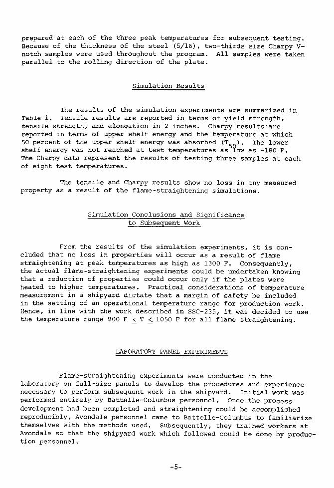
The results of the simulation experiments are summarized inTable 1. Tensile results are reported in terms of yield strength,
tensile strength, and elongation in 2 inches. Charpy results’are
reported in te~s of upper shelf energy and the temperature at which50 percent of the upper shelf energy was absorbed (T5 ). The lowershelf energy was not reached at test temperatures as $!OWas -180 F.The Charpy data represent the results of testing three samples at eachof eight test temperatures.
The tensile and Charpy results show no loss in any measuredproperty as a result of the flame-straightening simulations.
Simulation Conclusions and Significanceto Subsequent Work
From the results of the simulation experiments, it is con-cluded that no loss in properties will occur as a result of flamestraightening at peak temperatures as high as 1300 F. Consequently,the actual flane-straightening experiments could be undertaken knowing
that a reduction of properties could occur only if the plates wereheated to hiqher temperatures. Practical considerations of temperaturemeasurement in a shipyard dictate that a margin of safety be includedin the setting of an operational temperature range for production work.Hence, in line with the work described in SSC-235, it was decided to usethe temperature range 900 F < T ~ 1050 F for all flame straightening.
Flame-straightening experiments were conducted in thelaboratory on full-size panels to develop the procedures and experiencenecessary to perform subsequent work in the shipyard. Initial work wasperformed entirely by Battelle-Columbus personnel. Once the process
development had been completed and straightening could be accomplishedreproducibly, Avondale personnel came to Battelle-Columbus to familiarizethemselves with the methods used. Subsequently, they trained workers atAvondale so that the shipyard work which followed could be done by produc-
tion personnel.
-5-
.- —. —— —.——. —— ., .~— ,—
TABLE 1. RESULTS OF FLAME STRAIGHTENINGSIMULATIONS ON QTC MODIFIED STEEL
z
Treatment 2/3 Size CharpyResults Tensile Results
Temperature(F), Upper Shelf T50 Elongation
Time (Sec.) (ft-lb) (F} Oy (ksi) (% in 2 in] GT(ksi)
As-Received 29.0 -161 94.8 20.0 108.0
900, 15, Quench 28.5 -169 96.3 22.0 107.5
1100, 15, Quench 29.0 -175 95.6 21.5 107.5
1300, 15, Quench 30.0 <-182 98.7’ 20.5 108.5
I
I
I
II
I
It
-1
— —
+g”
—
FIGURE 1 - TEST PANEL
-6-
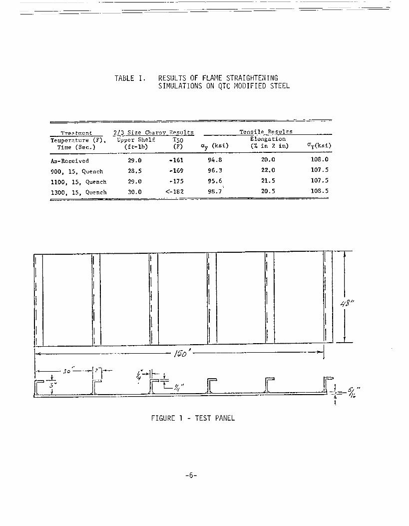
Laboratory Panel Procedures
The panel used for the laboratory phase of tie program isshown in Figure 1. The steel, plate thickness, angle size, and anglespacing are identical to that on the LASH ship structure. The onlydifference was that the experimental panel was not restrained aroundthe periphery as an actual structure would be.
The angles were welded using E1OO18M electrodes. Althoughone pass on each side would be normal fabrication practice, two passesper side were used in this program in order to increase the distortion.The as-welded panels contained an end-to-end bowing distortion of approxi-mately 2 inches over the 150–inch length and a stiffener–to-stiffener “oil-can” distortion of 0.2 to 0.4 inch.
A reference frame constructed of I-beams and bar stock wasused for all measurements which were made by dial gage. They were madeon the reverse side of the plate from the stiffeners at the stiffener
locations and midway between them over the middle 10 feet of the panel.
The flame heating was done using an oxyacetylene torch withan Oxweld 100 A3 tip. In accordance with the results of SSC-235, theplate was heated to an operating temperature range of greater than 900 Fand less than 1050 F as measured by temperature-indicating crayons. The900 F and 1050 F crayons were mounted in a single fixture so that bothcould be applied simultaneously. The temperature was measured every12 inches immediately after the flame had been removed. The water-quenchline was coupled to the torch so that both could be applied with one handby the operator. The quench was applied approximately two inches behindthe flame. Since the heating process was controlled on the basis of steelsurface temperature the specification of torch and flame characteristicssuch as standoff distance, gas-flow rates, and travel speed was unnecessary.
Previous direct experience with flame straightening, reported
in SSC-235, had involved work on heavily restrained panels 48 inches by48 inches by l/2 inch. It was determined that spot heating provided the
best control as a method of heat application for that panel and it wastherefore used to do the flame straightening. In addition to the plate
size and restraint, the 48–inch panels differed from those studied inthis program (Figure 1) in that butt welds for the previous panels weremade around the panel periphery so that the high area occurred in thepanel center. Since it was recognized that flame straightening shouldbegin at the convex surfaces, no heating was done around the welds sincethey were low points. In contrast, the panels used in this program con-tained six dotile-fillet welds and, since the reverse side of each was aconvex (or high) area, straightening was begun at the stiffener locations.Furthermore, since the convex regions ran parallel to the welds, line
-7-
heating matched the general outline of the distorted regions and wasapplied to the panels. It worked so well that, except for isolatedexperimentation with spot heating for comparative purposes, all straight-
ening was done by line heating.
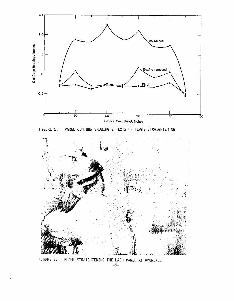
A typical example of the results obtained by flame straighteningin this program is shown in Figure 2. This is a plot of panel height as afunction of distance along the panel measured along the midpoint 124 inchesfrom the ends). The as–welded profile shows both the bowing distortion andthe localized oil-canning distortion with maxima at the stiffeners. Theoverall bowing distortion was removed by heating three lines over eachstiffener -- one line centered at the stiffener and one an inch to either
side. Three lines were required because the panel had been overwelded toincrease the distortion.
The results of subsequent line heating for removal of the oil-candistortion are also shown in Figure 2. The lines heated were both somerepeats of lines heated in removing bowing distortion and some additionallines placed closely to previous ones. The rule followed in selecting line
placement was to heat where the plate was high. The lines were done one at
a time so that the effect of each could be observed before proceeding.Referring to Figure 2, the following lines were required to remove the oil-can distortion after the bowing distortion had been removed:
TWO along the stiffener at 30 inchesone along the stiffener at 60 inchesThree along the stiffener at 90 inchesThree along the stiffener at 120 inches.
The final profile had a total variation in height of 0.15 inch over the150-inch panel length. This level of flatness far exceeds any required
in construction, and the effort to obtain this flatness was made only to
learn the capabilities of flame straightening.
Straightening was done by the same techniques both when thepanel was lying on the floor and when it was hanging vertically as heldby a crane.
spot-heating was used in addition to line heating on selectedpanels to compare the two processes. Spot heating was not used exclusively
on any panel but was only applied in a localized region. The distortion
was such that the convex area always occurred between the stiffeners onthe opposite plate side from the stiffener to plate welds. Distortion
removal is usually more conveniently done on this side rather than onthe side of the stiffeners. When spot heating was used, it was done on
the stiffener side of the panel. Line heating was both much faster and
gave greater distortion removal.
-8-
2.5
2.0
1.5
1.0
0.5
I I I I I I I 1 I
*
1 I I I t I I0
I !30 60 90 120 150
DistanceAlongPanel,inches
FIGURE 2. PANEL CONTOUR SHOWING EFFECTS OF FLAME STRAIGHTENING
::,$,. ~: “ ,,,! ,.
“ I
,,,,..., ,,, .,,,‘, ,,)!’,,‘)
,* ‘. ;:’%%i’ ~,& .:,! >’ .’,
,,’!,,, .,
FIGURE 3. FLAME STRAIGliTENING THE LASH PANEL AT AVONDALE
-9-
The laboratory panel work showed that line heating could beused effectively in distortion removal. The principal features of the
technique were to use a working temperature between 900 and 1050 F andto apply the quench continuously at a point approximately 2 inchesbehind the flame. All lines were at the high points which occurredin the region of the stiffener–to-plate welds on the opposite side fromthe stiffener.
The laboratory panel work also resulted in the training ofAvondale personnel in the techniques ~or flame s’craightening quenched-and-tempered steel. This training was performed on panels of comparable
size, thickness, stiffener spacing, and steel to those of the LASH shipto be straightened at Avondale by Avondale personnel in the subsequentphase.
SHIPYARD STRAIGHTENING
The shipyard straightening was done at Avondale on a IASH ship
panel by Avondale production workers. The Battelle-Columbus investigator
was present as an observer only.
The panel was essentially the same as that used in the labora-tory experiments with respect to steel chemistry, plate thickness, andstiffener spacing. The principal difference is that the LASH panel waswelded into the structure; whereas the laboratory panel had been free onthe ends.
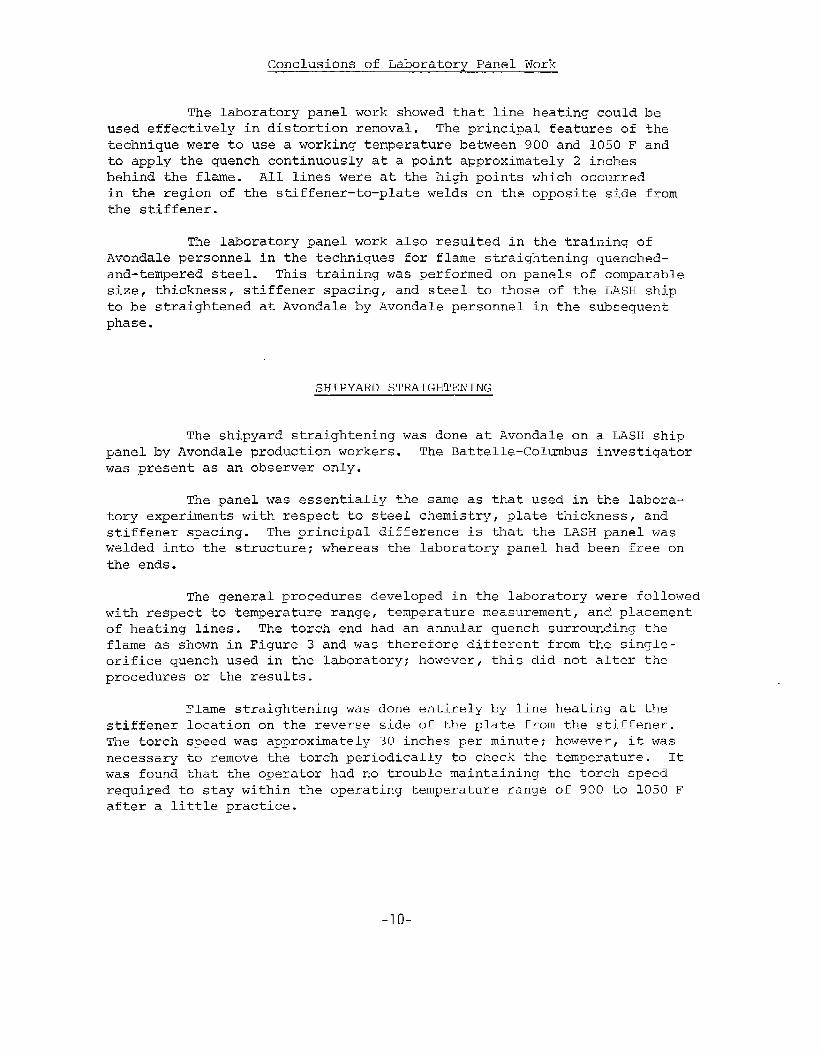
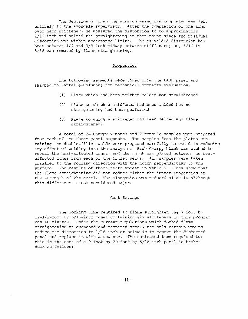
The general procedures developed in the laboratory were followedwith respect to temperature range, temperature measurement, and placement
of heating lines. The torch end had an annular quench surrounding the
flame as shown in Figure 3 and was therefore different from the single-orifice quench used in the laboratory; however, this did not alter the
procedures or the results.
Flame straightening was done entirely by line heating at thestiffener location on the reverse side of the plate from the stiffener.The torch speed was approximately 30 inches per minute; however, it wasnecessary to remove the torch periodically to check the temperature. Itwas found that the operator had no trouble maintaining the torch speedrequired to stay within the operating temperature ranqe of 900 to 1050 Fafter a little practice.
-1o-
The decision of when the straightening was completed was left
entirely to the Avondale supervisor. After the completion of one line
over each stiffener, he measured the distortion to be approximatelyl/15 inch and halted the straightening at that point since the residualdistortion was within acceptance limits. The as-welded distortion had
been between l/4 and 3/8 inch midway between stiffeners; so, 3/16 to5/16 was removed by flame straightening.
Properties
The following segments were taken from the LASH panel andshipped to Battelle-Columbus for mechanical property evaluation:
(1) Plate which had been neither welded nor straightened
(2) plate to which a stiffener had been welded but nostraightening had been performed
(3) Plate to which a stiffener had been welded and flamestraightened.
A total of 24 Charpy V–notch and 2 tensile samples were preparedfrom each of the three panel segments. The samples from the plates con-
taining the double-fillet welds were prepared carefully to avoid introducingany effect of welding into the analysis. Each Charpy blank was etched ko
reveal the heat-affected zonesj and the notch was placed between the heat-affected zones from each of the fillet welds. All samples were taken
parallel to the rolling direction with the notch perpendicular to thesurface. The results of these tests appear in Table 2. They show thatthe flame straightening did not reduce either the impact properties orthe strength of the steel. The elongation was reduced slightly although
this difference is not considered major.
Cost Savings
The working time required to flame straighten the 7-foot by12–1/2-foot by 5/16-inch panel containing six stiffeners in this programwas 40 minutes. Under the current regulations which forbid flamestraightening of quenched-and-tempered steel, the only certain way toreduce the distortion to 1/16 inch or below is to remove the distortedpanel and replace it with a new one. The estimated time required for
this in the case of a 9–foot by 20–foot by 5/16–inch panel is brokendown as follows:
-11-
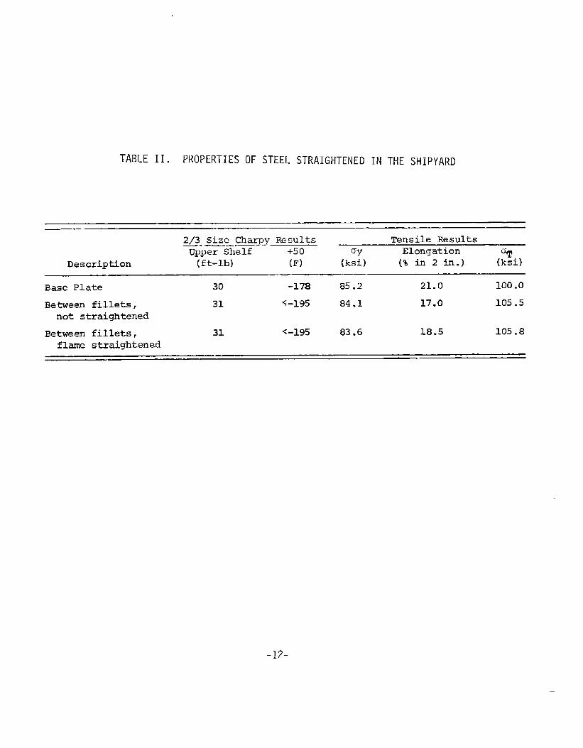
TABLE II. PROPERTIES OF STEEL STRAIGHTENED IN THE SHIPYARD
2/3 Size Charpy Results Tensile ResultsUpper Shelf +50 Elongation ~~
Description (ft-lb) (F) (k:) (% in 2 in.)
Base Plate 30 -17s 85.2 21.0 100.0
Between fillets, 31 6-195 84.1 17.0 105.5not straightened
Between fillets, 31 <-195 83.6 18.5 105.8
flame straightened
-12-
—
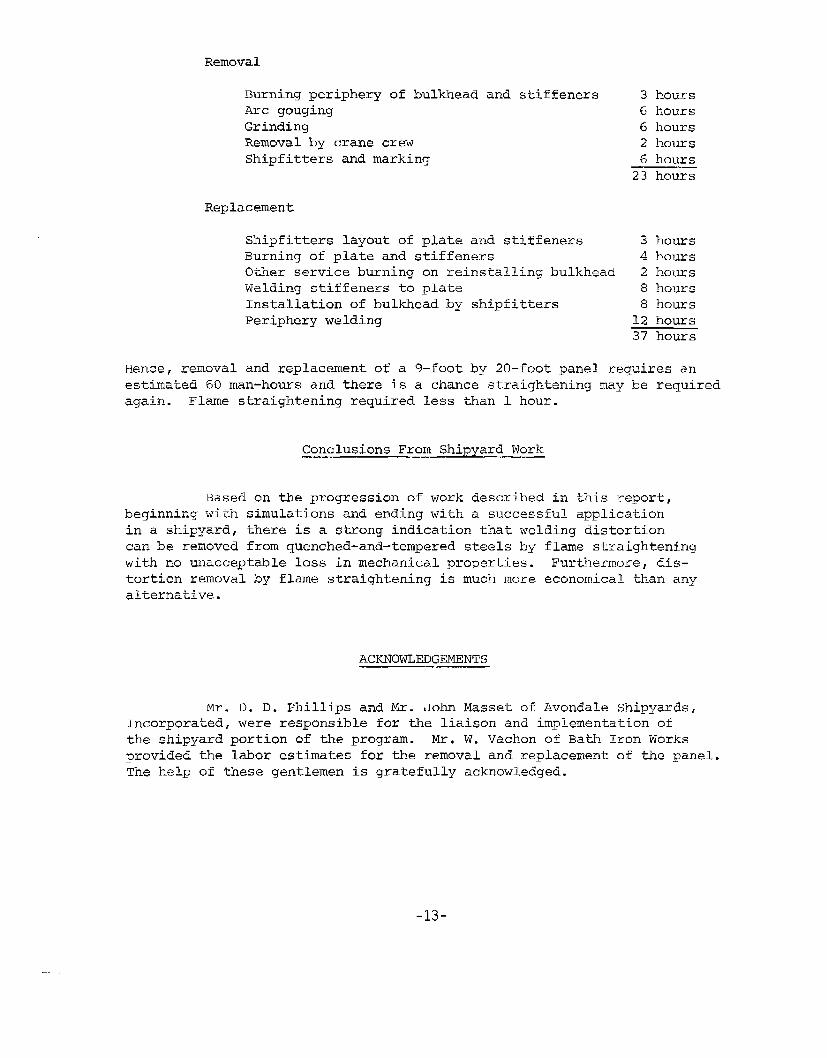
Removal
Burning periphery of bulkhead and stiffeners 3 hoursArc gouging 6 hoursGrinding 6 hoursRemoval by crane crew 2 hoursShipfitters and marking 6 hours
23 hours
Replacement
Shipfitters layout of plate and stiffeners 3 hoursBurning of plate and stiffeners 4 hoursOther service burning on reinstalling bulkhead 2 hoursWelding stiffeners to plate 8 hoursInstallation of bulkhead by shipfittiers 8 hoursPeriphery welding 12 hours
37 hours
Hence, removal and replacement of a 9-foot by 20-foot panel requires anestimated 60 man-hems and there is a chance straightening may be requiredagain. Flame straightening required less than 1 hour.
Based on the progression of work described inbeginning with simulations and ending with a successful
this report,application
in a shipyard, there is a strong indication that welding distortioncan be removed from quenched-and-tempe~ed steels by flame straighteningwith no unacceptable loss in mechanical properties. Furthermore, dis-tortion removal by flame straightening is much more economical than anyalternative.
ACKNOWLEDGEMENTS
m. D. D. Phillips and Mr. John Masset of Avondale Shipyards,Incorporated, were responsible for the liaison and implementation ofthe shipyard portion of the program. Mr. W. Vachon of Bath Iron Worksprovided the labor estimates for the removal and replacement of the panel.The help of these gentlemen is gratefully acknowledged.
-13-
Unclassified-----------,.+..-,,..-,-.,-r.,-,,,..-.--.,.1-—m-..V—,L-..J,SELURI 1 T ~~n>anri~finiuw u. B n,> r--i= (.. ZZO8, “ata S, E:. r-u,
REPORT DOCUMENTATION ?AGEREAD INSTRUCTIONS
BEFORE CC)hfPLETING FORM
REPORT NUMBER 2. GOVT ACCES510N NO. 3. REclplENT’$cATALoG NuMBER
7~c-?47,.TITLE (md Subtitle) 5. TYPE OF REPORT h PERIOD COVERED
Final ReportFLAME STRAIGHTENING QUENCHED-AND-TEMPEREDSTEELS IN SHIP CONSTRUCTION 5.PERFORMING• RG. REPoRT NuMBER
‘. AUTHOR(*) 8. CONTRACTOR GRANT NUMBER(S)
R. L. Rothman Contract NOO024-73-C-5173
1.PERFORMING ORGANIZATION NAME AND ADDRESS 10. PROGRAM ELEMENT, PROJECT, TASKAREA& WORK UNIT NUMBERS
Battelle-Coltius Laboratories505 King Avenue, ColtiUs, Ohio 43201
1.CONTROLLING OFFICE NAME AND ADDRESS 12. REPORT DATE
Department of the NavyNaval Ship Systems Command, Washington, D.C. 13. NUMBEROF PAGES
7i-136n 1314. MONITORING AGENCY NAME & ADD RESS(ii different from Controlling offjte) 15. SECURITY CLASS. (of fhi. ,ep~,t)
Unclassified15a. DECLAS51FlCAT10N/DOWNGRAIXNG
SCHEDULE
16. DISTRIBUTION STATEMENT (offhi*R6POr~)
DISTRIBUTION OF THIS DOCUMENT IS UNLIPIITEII
17. DISTRIBUTION STATEMENT (ef iha abstract entered in BIoek 20, if diffdrefit from i?ePorf)
UNLIMITED
18,SUPPLEMENTARY NOTES
lg. KEY WORDS (Continue on fevetae a{de if necaaew ~d ~d-ntify by block number)
Flame straightening, quenched and tempered steels, shipbuilding, welddistortion.
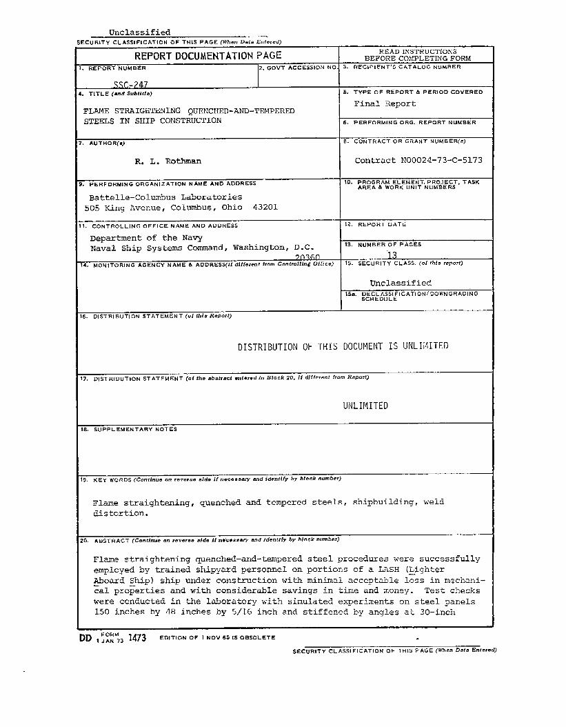
m. ABSTRACT (continue O.-I r***rBe Bide If ne”cm=-w nnd Idcntffy @ block -Umber)
Flame straightening quenched-and-temperedsteel procedures were successfullyemployed by trained shipyard personnel on portions of a LASH (Lighter~oard Ship) ship under construction with minimal acceptable l~ss in mechani-cal pro~erties and with considerable savings in time and money. Test checkswere conducted in the laboratory with simulated experiments on steel panels150 inches by 48 inches by 5/16 inch and stiffened by angles at 30-inch
-L-..DD lj~~~3 1473 EDITION OF 1NOV651SOBSOLETE .
SECURITY CLASSIFICATION OF THIS PAGE (Wh.n Data Entermd)
20. ABSTRACT (Cont.)
intervals. As much as two inches of unfairness of the plating waseffectively removed. A recommended procedure is presented.
43793
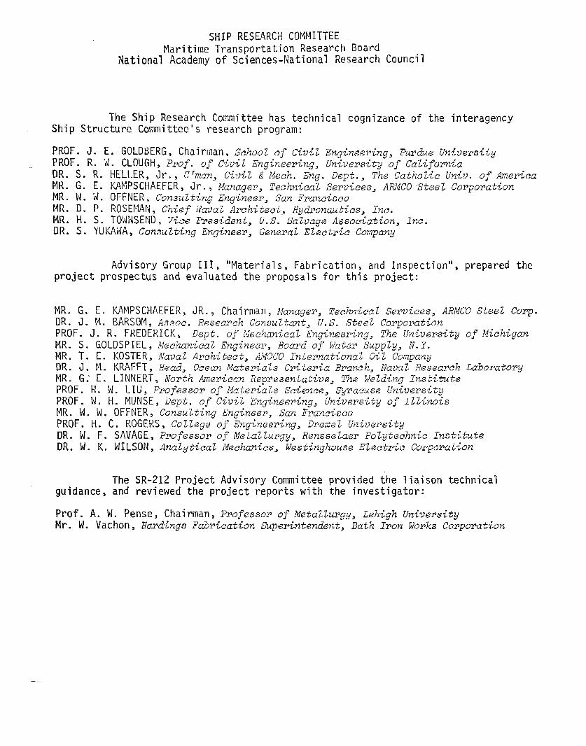
SHIP RESEARCH COMMITTEEMaritime Transportation Research Board
National Academy of Sciences-National Research Council
The Ship Research Committee has technShip Structure Committee’s research program:
PROF. J. E. GOLDBERG, Chairman, WZOOZ ofciviZPROF. R. ‘d. CLOUGH, Prof. o.f Civil Ewineerinu.
cal cognizance of the interagency
Engineering, Purdue UniversityUniverwit3 of California
DR. S. R. HELLER, Jr., ktma~, Cioil &“Meeh. E&. Dept., T~EZ~atho~~c Univ. of AmericaMR. G. E. ICAMPSCHAEFER, Jr., ~anage~, ~eehnic~l seYv~ces, ARMco~~ee~ c~rpopa~~onMR. N. ii.OFFNER, Consulting Engineer, San FranciscoMR. D. P. ROSEMAN, Chief ilavulArc.hite,ct,Hydponautics, Inc.MR. H. S. TOWNSEND, Vice President, U.S. SaZvage Association, Inc.DR. S. YUKAW, Consult-ingEnginee~, General Electric Company
Advisory Group III, “Materials, Fabrication, and Inspection”, prepared theproject prospectus and evaluated the proposals for this project:
MR. G. E. KAMPSCHAEFER, JR. , Chairman, Manage?, Technical Services, ARMCO Steel Corp.DR. J. !4.BARSOM, Assoc. Research Consultant, U.S. Steel CorporationPROF. J. R. FREDERICK, Dept. of i,ieehaniealEngineming, The University of MichiganMR. S. GOLDSPIEL, Mechanica2 Enginee~, Board of Water SuppZy, N.Y.MR. T. E. KOSTER, flava~Architect, AMOCO International Oil CompanyDR. J. M. KRAFFT, Head, Ocean MateriaZs Critwia ~ra=h, Naval Research tiborato~yMR. G.’E. LINNERT, North Ame~iean Representative, Th@ Welding InstitutePROF. 1-1.N. LIU, Professor of Materials Science, Syracuse UniversityPROF. Id.H. MIJNSE, Dept. of Civil Engineering, University of IllinoisMR. N. ‘d.OFFNER, Consulting Engineer, San FranciscoPROF. 1-1.C. ROGERS, Coll~ge of Zngkering, itreze~UniversityDR. 1. F. SAVAGE, Professo~ of MetaZZurgy, RensseZae~ Polytechnic InstituteDR. W. K. NILSON, Analytical Mechanics, Westinghouse Electric Corporation
The SIR-212 Project Advisory Committee provided the liaison technicalguidance, and reviewed the project reports with the investigator:
Prof. A. U. pense, Chairman, Professor of Meta22urgy, Lehigh UniversityMr. W. Uacbn, Hardings Fabrication Superintendent, Bath Iron WoxJksCorpo~ation
SHIP STRUCTURE COMMITTEE PUBLICATIONS
SSC-238,
SSC-239,
SSC-240,
SSC-241,
SSC-242,
SSC-243,
SSC-244>
SSC-245,
SSC-246,
SL-7-1,
SL-7-2,
SL-7-3,
SL-7-4,
(
(
These docwmntis are distributed by tha NationaZ TachnicaLInformationService, Sp~ingfield, Vu. 22151. These doe-wwnts ha-w been announcad in the Clec&nghouse journa~U.S. Govawwnt Research & Development Reports (USGRDR)unde~ tha indicatedAD numbem.
Design and Installationof a Ship Response InstrumentationSystemAboard the SL-7 Class ContainershipS.S. SEA-LAND McLEAflbyR. A. Fain. 1973. AD 780090
Wave Loads in a Model of -theSL-7 ContainershipRunning at ObliqueHeadings in Regular Waves by J. F. Dalzell and M. J. Chiocco. 1973.AD 780065
Load C~itw<a for Ship Struehwal Design by E. V. Lewis, R. van Hooff,D. Hoffman, R. B. Zubaly, and W. M. Maclean. 1973. AD 767389
ThmmoeZastie Model Studies of C~yogenicTankw Stxwetwws byH. Becker and A. Colao. 1973. AD 771217
Fast Fraetwe Resistance and C~aek Amest in Structural Steels byG. T. Hahn, R. G. Hoagland, M. F. Kanninen, A. R. Rosenfield andR. Sejnoha. 1973. AD 775018
StzweturalAnalysis of SL-7 ContainershipUnder Combined Loading ofVwtieaZ, Late?al and Torsional Moments Using Finite Element Techniquesby A. M. Elbatouti, D. Liu and H. Y. Jan. 1974.
Fracture-Cont~olGuidelinesfor Welded Steel Ship HuLLs by S. T. Rolfe,D. M. Rhea, and B. O. Kuzmanovic. 1974.
A Gu<de Fop Inspection of High-StrwzgthSt~e’LWeZdments by The WeldFlaw Evaluation Committee. (To be published)
TheoreticalEstimates of-Wave Loads On the SL-7 ContainershipInReguZa~ and Irregular Seas by P. Kaplan, T. P. Sargent and J. Cilmi.1974.
SL-7 PUBLICATIONS TO DATE
$SC-238) - Design and Installationof a Ship Response InstrumentationSystem Abocwd the SL-7 Class Containers@ S.S. SEA-LAND McLEAN byR. A. Fain. ‘1973. AD 780090
SSC-239) - Wave Loads in a Model of the SL-7 ContainerskipRunning atOblique Headings in Regular Waves by J. F. Dalzell and M. J. Chiocco.1973. AD 780065
SSC-243) - Structwal Analysis of SL-7 Con-tainershipUnder CombinedLoading of Ve~tieal,Lateral and To?sionalMoments Using Finit@ ElementTechniques by A. M. Elbatouti, D. Liu and H. Y. Jan” 1974.
:SSC-246) - Theo?etiealEstimatesin Regular and Imegular Seas by1974.
of wave Loads onP. Kaplan, T. P.
the SL-7 ContainershipSargent and J. Cilmi.