Embed Size (px)
Citation preview

Flame Photometer
FP-640Operation Manual
PLEASE READ THIS MANUAL CAREFULLY BEFORE OPERATIONHagavish st. Israel 58817 Tel: 972 3 5595252, Fax: 972 3 5594529 [email protected]
MRC.9.16

Note
This manual only applies to FP-640 flame photometer.
Without the prior written permission of our company, part or all of this manual are
not allowed to copy, reproduce or translate into its languages. The contents of this
manual are subject to change.

Contents
1 Principles, Applications and Features.........................1
1.1 Principles..........................................................1
1.2 Applications..................................................... 2
1.3 Features........................................................... 3
2 Technical Indicators and Specifications...................... 4
2.1 Technical Indicators......................................... 4
2.2 Specifications................................................. 10
3 Installation Instructions............................................ 11
3.1 Conditions...................................................... 11
3.2 Unpacking...................................................... 12
4 Instrument Appearance and Structure.....................13
4.1 Instrument Appearance.................................13
4.2 Instrument Structure..................................... 14
5 Installation Debugging.............................................. 20
5.1 Installation..................................................... 20
5.2 Debugging...................................................... 21
5.3 Keypad Operations........................................ 23
6 Operations.................................................................24
6.1 Curve calibration............................................24
6.2 Sample Test.................................................... 28
6.3 System Configuration.....................................32
6.4 Direct Reading of Proportional Value............ 34
7 Mother Liquor........................................................... 36
7.1 Potassium and Sodium..................................... 36
7.2 Potassium Oxide and Sodium Oxide.................37
7.3 Potassium and Sodium..................................... 38
7.4 Conversion between mmol/L and μg/mL.........39
8 Maintenance and Troubleshooting.......................... 40
8.1 Notes.............................................................. 40
8.2 Maintenance.................................................. 42
8.3 Troubleshooting............................................. 43
9 Warranty................................................................... 45

Flame Photometer Series Manual
1
1 Principles, Applications and Features
1.1 Principles
Flame Photometer applies the emission spectrum as the basic principle, which uses the flame heat and excites part of
the atoms in alkaline earth metal. The atoms absorb energy and transit to the previous energy level; when it drops to the
normal energy level, it has to release energy. The released energy has only the spectral characteristics, namely, a certain
wavelength range. For example, place salt in the flame, and it will display yellow color, due to the sodium atoms in flames
falling back to the normal energy level and displaying yellow spectrum. It is often called “flame reaction”. Different alkali
metals or alkaline earth metals in the flame display different colors. Qualitative tests can be carried out together with
different filters. The flame color is proportional to the concentration of atoms contained in the solution, which constitutes a
quantitative test basis. This method is typically referred to as flame photometry, and this type of equipment is known as
flame photometer.
As the flame temperature is not high, measured atoms release limited energy. At the same time of the combustion
process, self-absorption and self-erosion exist; therefore, the test is linear only in low concentrations. As the flame

Flame Photometer Series Manual
2
temperature is not high, measured atoms release limited energy. At the same time of the combustion process,
self-absorption and self-erosion exist; therefore, the test is linear only in low concentrations. Flame photometer is a relative
measuring appliance, and the concentration values of tested samples are relative values of standard solution concentration
under the same test condition. Therefore, before the test a group of the corresponding standard solutions must be prepared,
then the calibration operation starts, standard curves are drawn artificially or through mapping equipments, finally test
samples can be tested and their concentration or other necessary calculation data are obtained.
The instrument is small in size, simple in structure, and easy to operate. It is also stable and reliable, and apply liquefied
petroleum gas as fuel.
1.2 Applications
Testing cement, glass, ceramics, refractory materials and other construction materials;
Testing fertilizers and soil;
Testing products of mining, petroleum, metallurgy, and chemical products;
Testing pharmaceutical, beverages and other food;
Testing Municipal solid waste (MSW);
Various laboratory tests for scientific research, health, education and other fields.

Flame Photometer Series Manual
3
1.3 Features
Direct reading of the element concentrations;
7-inch color LCD touch screen;
An automatic calculation of correlation coefficient and pre-selection of flame sizes;
A flameout protection device for safety;
Direct printing devices; (To be equipped with a printer)
An USB interface to connect with computer, with software to do data processing.

Flame Photometer Series Manual
4
2 Technical Indicators and Specifications
2.1 Technical Indicators
6400A FP-640 FP6410 FP6430 FP6431 FP6432 FP6440 FP6450
stability Continuous sampling of standard solution, the biggest change in the relative volume
in 15s is less than 3%. Test once every minute, and test 6 times in total, the biggest
change in the relative volume is less than 15%.
Reproducibility ≤3%
Response Time <8 s
Suction & Spray
Volume of Sample
<6mL/min
Print Function — — Optional USB Data Output —
Automatic
Calculation
— —

Flame Photometer Series Manual
5
6400A
K:
≤0.005
K:
≤0.005
K:
≤0.005
K:
≤0.005
K:
≤0.005
K:
≤0.005
K:
≤0.005
K:
≤0.005
Na:
≤0.03
Na:
≤0.03
Na:
≤0.03
Na:
≤0.03
Na:
≤0.03
Na:
≤0.03
Na:
≤0.03
Na:
≤0.03
— — — Li:
≤0.021
— — Li:
≤0.021
Li:
≤0.021
— — — — Ca:
≤0.075
— Ca:
≤0.075
Ca:
≤0.075
Linear Error
mmol/L
— — — — — Ba:
≤0.066
— Ba:
≤0.066
FP-640 FP6410 FP6430 FP6431 FP6432 FP6440 FP6450

Flame Photometer Series Manual
6
6400A
K:
≤0.004
K:
≤0.004
K:
≤0.004
K:
≤0.004
K:
≤0.004
K:
≤0.004
K:
≤0.004
K:
≤0.004
Na:
≤0.008
Na:
≤0.008
Na:
≤0.008
Na:
≤0.008
Na:
≤0.008
Na:
≤0.008
Na:
≤0.008
Na:
≤0.008
— — — Li:
≤0.015
— — Li:
≤0.015
Li:
≤0.015
— — — — Ca:
≤0.050
— Ca:
≤0.050
Ca:
≤0.050
Detection limit
mmol/L
— — — — — Ba:
≤0.044
— Ba:
≤0.044
FP-640 FP6410 FP6430 FP6431 FP6432 FP6440 FP6450
Flame Photometer Series Manual
7
6400A
K:
≤7nm
K:
≤7nm
K:
≤7nm
K:
≤7nm
K:
≤7nm
K:
≤7nm
K:
≤7nm
K:
≤7nm
Na:
≤5nm
Na:
≤5nm
Na:
≤5nm
Na:
≤5nm
Na:
≤5nm
Na:
≤5nm
Na:
≤5nm
Na:
≤5nm
— — — Li:
≤7nm
— — Li:
≤7nm
Li:
≤7nm
— — — — Ca:
≤7nm
— Ca:
≤7nm
Ca:
≤7nm
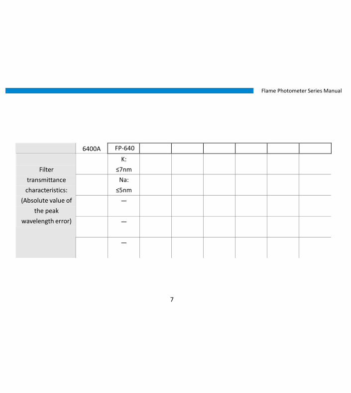
Filter
transmittance
characteristics:
(Absolute value of
the peak
wavelength error)
— — — — — Ba:
≤7nm
— Ba:
≤7nm
FP-640 FP6410 FP6430 FP6431 FP6432 FP6440 FP6450

Flame Photometer Series Manual
8
6400A
K:
≤15nm
K:
≤15nm
K:
≤15nm
K:
≤15nm
K:
≤15nm
K:
≤15nm
K:
≤15nm
K:
≤15nm
Na:
≤15nm
Na:
≤15nm
Na:
≤15nm
Na:
≤15nm
Na:
≤15nm
Na:
≤15nm
Na:
≤15nm
Na:
≤15nm
— — — Li:
≤15nm
— — Li:
≤15nm
Li:
≤15nm
— — — — Ca:
≤15nm
— Ca:
≤15nm
Ca:
≤15nm
Filter
transmittance
characteristics:
(half-width)
— — — — — Ba:
≤15nm
— Ba:
≤15nm
FP-640 FP6410 FP6430 FP6431 FP6432 FP6440 FP6450

Flame Photometer Series Manual
9
6400A
K:
≤0.5%
K:
≤0.5%
K:
≤0.5%
K:
≤0.5%
K:
≤0.5%
K:
≤0.5%
K:
≤0.5%
K:
≤0.5%
Na:
≤0.5%
Na:
≤0.5%
Na:
≤0.5%
Na:
≤0.5%
Na:
≤0.5%
Na:
≤0.5%
Na:
≤0.5%
Na:
≤0.5%
— — — Li:
≤0.5%
— — Li:
≤0.5%
Li:
≤0.5%
— — — — Ca:
≤0.5%
— Ca:
≤0.5%
Ca:
≤0.5%
Filter
transmittance
characteristics:
(background
transmittance)
— — — — — Ba:
≤0.5%
— Ba:
≤0.5%
FP-640 FP6410 FP6430 FP6431 FP6432 FP6440 FP6450

Flame Photometer Series Manual
10
2.2 Specifications
FP640
Display 7-inch color LCD touch screen
Spectroscopic
methods
Photoelectric
conversion
component
Interference filters Silicon photocell
Dimensions l×b×h 400mm×250mm×500mm
Weight 8.0Kg

Flame Photometer Series Manual
11
3 Installation Instructions
3.1 Conditions
The instrument should be placed on a solid stable work station which meets the requirements for laboratory
environment, keeps the indoor environment clean, and avoids serious dust pollution.
A working environment to protect the instrument requirements are as follows:
The ambient temperature of laboratory remains between 10 ℃�to 35 ℃, with relative humidity less than 85%.
Avoid sunlight, free of vibration and strong airflow and erosion of corrosive substances, and equipped with fire
extinguishers.
Power supply voltage is AC220V ± 22V, frequency of 50Hz ± 1Hz, and must be equipped with a good grounding.
Away from high-intensity magnetic field, electric field, and the occurrence of high-frequency waves of electrical
equipment. Avoid sharing the same power outlet with other devices.
Note: If the power supply voltage fluctuates dramatically, it is recommended to use more than 500W AC
electronic power supply.

Flame Photometer Series Manual
12
3.2 Unpacking
Open along with the sealing (please save package box, prepare for the moving needs), in accordance with
accessories and spare parts list to check the host machine and spare parts. If there is anything missing, please contact
the local sales representative or directly contact our company.

Flame Photometer Series Manual
13
4 Instrument Appearance and Structure
4.1 Instrument Appearance

Flame Photometer Series Manual
14
4.2 Instrument Structure
4.2.1 Atomizing System
The system consists of air compressor, air filtration valve, sprayer, and atomizing chamber.
◆�Air Compressor:
The air compressor (see the right figure) is oil free. The max. output pressure is 0.20MPa, and the max. air flow is
0.9m3/min. The input power shall not be greater than 200W. The power supply voltage is 220V±22V. It's better to have
an independent outlet with a switch.
◆�Air Filter Valve: Air released by the air compressor flows through air filter valves, and becomes cleaner, drier, with more stable
pressure. The air filter valve (see the left figure) has two functions: one is to stabilize pressure, and the other is to filter.
The way to adjust the air pressure is as following: pull out the control valve at the top of air filter. Rotate clockwise to
increase output pressure, and counterclockwise rotation reduces output pressure. After working for a period of time,
the air filter valves have some water. The water should be excluded on a regular basis. (For drainage method, please
refer to "maintenance")

Flame Photometer Series Manual
15
◆�Atomizing Chamber:
Passing the filter valve, the air flows into the atomizing chamber and is sprayed out by the sprayer in high speed.
Since it is equipped with intake pipe, the negative pressure is formed at the open end of the pipe, which makes the
sample solution spray out through the intake pipe. At this time, high-speed water flow collides on the atomizing
chamber walls, and then some of the solution becomes minor water drops. And the relative bigger drops which fall
down on the bottom of the chamber are drained through latex tube and collected into the waste liquid container.

Flame Photometer Series Manual
16
4.2.2 Gas System
◆�LPG:
The instrument uses liquefied gas as fuel, which is liquefied petroleum gas, briefly LPG. If an odorant is smelled
in the work place, make sure to double check if there is any leak of LPG.
Users themselves need to prepare the LPG cylinder. When buying cylinders, users must check the quality of
suppliers, namely, cylinder safety must be approved by the local technical supervision department. The workplace must
be well-ventilated. When cylinders are placed in a box, the lower part of the box must have several ventilation holes.
Cylinders cannot be placed horizontally instead of vertically, or exposed to direct sunlight; besides, flammable materials
must not be placed near them. Rubber tubes cannot be used for more than a year.
If unknown leakage of LPG occurs, users must immediately switch off cylinders, and open doors and windows. Do not
switch on/off electrical appliances. Do not let objects collide. If it is necessary to evacuate staff, don't panic and act
calmly. Report to relevant department, if necessary.

Flame Photometer Series Manual
17
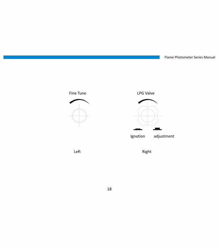
◆�Gas Valve:
The gas valve consists of three parts: ignition device, adjusting device, and flameout protection device.
1) Ignition device: Users start from right, press the gas adjustment knob, and turn left 90°. Now the ignition device
automatically is powered on, and pulse generator generates a high-voltage electric spark on the verge of the
burning head. Now liquefied petroleum gas has overflowed from the head. When it meets electric spark, it
automatically induces ignition. Hold on the adjustment knob for a few seconds, and then release it. The flame is
burning normally. Then turn the adjustment knob to the left, the flame gets smaller and smaller as it goes far left.
2) Flameout protection device: without igniting, if users turn on the switch of the cylinder, LNG will not overflow from
the burning head even if the adjustment knob is at the working position. When the ignition is successful, the
thermocouple installed in the head starts working and triggers electromagnetic valve to work. Since the magnetic
valve is open and the flame will not extinguish even if letting go of hand. If the flame is off accidentally,
thermocouple cools and triggers electromagnetic valve to shut off the cylinder.
◆�Fine Tuning Knob: The stability of testing is closely related with the stability of flame. The instrument is equipped with a fine tuning
knob to make sure the stability of burning. After ignition, the gas valve is placed on the left, and the fine tuning knob can
be used to control the flame until it meets the user ’s requirement.
Flame Photometer Series Manual
18
Fine Tune LPG Valve
Ignation adjustment
Left Right

Flame Photometer Series Manual
19
4.2.3 Measuring Device
Measuring device is a set of optical and electrical appliances, the optical part of which consists of protecting glass
and interference filters. The protecting glass prevents dust from contaminating the interference filter and the flame
burning, so as to extend the service life of interference filters. Users should use interference filters with corresponding
wavelengths to test different metal atoms. If the user needs to test other metal atoms, the filter shall be changed to
meet the testing requirement. Electrical appliances transfer the solar energy into electric energy, which is displayed on
the screen after signal magnification and being processed into analog quantity by CUP data processor. The CUP data
processor can also perform piecewise or linear regression testing, which saves a lot of efforts. The testing results can be
stored or printed out.
Flame Photometer Series Manual
20
5 Installation Debugging
5.1 Installation
1) Install JYT-0.6 valve at the exit of liquefied petroleum gas cylinders. The valve joint is L-thread, namely L is
tight, D is loose, and it must be tightened. Exit of the valve and the entrance of the equipment have tapered
connectors, connecting with rubber tubes (which can be found in the spare parts) and the fixed chuck must
be installed at the link. Use wrenches or screwdrivers to tighten the fixed chuck. After installation, users must
check the quality of the installation. Open cylinder switches, blow with hands the air at the joint, and smell to
see if it smells, or put soapy water at the joints, and observe whether there are air bubbles out.
2) Connect the exit of air compressor and the air valves of the air filtration with a 6 × 4PU pipe. Insert the pipe to the
mouth, and it has to reach the bottom. If users can pull out PU pipe only by the hand, it must be re-installed.
When it is necessary to remove the tube, users can press and hold down the joint and pull out the tube.
3) Insert one end of the latex tube (waste water) into the outlet of waste water cup, the other focuses to the
container of the waste liquid.

Flame Photometer Series Manual
21
4) Insert the other end into the socket of the power grid; air compressor outlet of the power grids should be
connected to switching devices. Power grid must be well grounded.
5) If the equipment is connected with a computer, a USB cable can be used and the related software must be
installed on the computer.
5.2 Debugging
5.2.1 Sprayer
1) Turn on the air compressor. Move the knob of the air filter valves to make pressure gauge display 0.15MPa.
2) Put the capillary into distilled water, after removing the cover from the chimney, vapor will be seen only when
ignition has not been done, i.e. the combustion head is cool. Otherwise, vapor cannot be seen.
3) Check whether there is water draining from the waste liquid container. If it doesn’t work, pinch the latex tube
under the atomizing chamber.

Flame Photometer Series Manual
22
5.2.2 Cautions when switching on/off
1) Switch on the host and the air compressor, and put the sampling capillary into distilled water.
2) Switch on the cylinder, and implement the ignition.
3) Before shutdown, wash with distilled water for 5min, switch off the cylinder and turn off the gas valve knob (the fine
tuning knob shall remain on, and the flame will remain the same when the instrument is switched on and ignition is
on). Finally, shut down the power of the instrument and air compressor.
5.2.3 Ignition Preheating
1) Switch on the power from the back of the panel.
2) Press the adjustment knob of gas valve on the panel, "da, da, da" Will be heard, at the same time, ELECTRIC SPARK
will be seen between in the ignition electrode and burning head.
3) Switch on the air compressor, and insert the plastic capillary into distilled water.
4) If the machine is new or not used for a long time, it should spray for a few minutes before ignition until the liquid
discharge pipe of the waste water cup overflows. If water accumulates in the atomizing chamber, squeeze the latex
repeatedly with fingers, until the liquid discharge pipe naturally overflows.

Flame Photometer Series Manual
23
5) Switch on the gas cylinder (counterclockwise).
6) Press and hold down the knob of the gas valve, turn left 90 ° from the closing position. Hold the knob and it will
ignite. After ignition, press the knob before release.
7) After ignition, turn the gas valve knob to the left (don’t press it down) until it couldn’t move. Then the fine tuning
knob can be used to control the flame.
8) After ignition, the device should be preheated 30min in the state of putting in distilled water before performing
testing work. (Note: after ignition, the instrument shall burn only when capillary is inserted into water to inject
sample and the liquid is draining from waste liquid container.
5.3 Keypad Operations
The series of instrument is operated through the pop-up touch keypad. There are number and letter keys.
Number keys: 【� CE 】� is to clear data; 【� Cancel 】� is to cancel the current input; 【� Enter 】� is to confirm
the input data.
Letter keys:【� CE 】is to clear data;【� Cancel 】�is to cancel the current input; 【� Enter 】is to confirm the input
data.
【� ← 】is to clear last character or backspace.

Flame Photometer Series Manual
24
6 Operations
When turned on, the instrument will automatically perform the series of system self-test.
After the self-test, it enters the main menu interface.
6.1 Curve calibration
Click the [Menu] button on the top right corner of the screen to return to the main menu interface.
6.1.1 Interface Introduction
Curve calibration interface consists of an analog value display field, calibration area and functional operation
components.
The upper end of the table shows the current analog value of corresponding elements. Different elements are all

Flame Photometer Series Manual
25
tested simultaneously.
The central of the table is test operation area, which can perform curve calibration. The series of instruments can
calibrate 12 curve points for each element, display 6 lines per page, which can be flipped with the right side of the
screen buttons [↑] and [↓]. Numbering is only served as reference mark and each line can be clicked to perform
calibration. C column data represents concentration values (which need to be entered manually), and A column
data indicates an analog value.
Form the lower functional operating area. Each button corresponds to a different operation content.
[curve] after completion of the calibration, click on the button to automatically generate the curve, and the
interface will switch to curve generation interface with the grid.
[Enter] is used to confirm the single-line calibration data, indicating that the line calibration is complete.
[Clear] is to clear all of the current calibration data.
[Print] is to print this calibration data.
[Storage] is to store the current calibration data. Click it to enter calibration dedicated file list interface. (See 6.1.3)
[Call] is to bring up once a stored calibration data. Click it to enter calibration dedicated file list interface. (See
6.1.3)

Flame Photometer Series Manual
26
6.1.2 Calibration Example
1) Get the calibration solution ready (at least 2 kinds of solution with different concentrations). Otherwise it is
impossible to form two different calibration points, and unable to form curves.
2) Put the injection pipette into the vessel containing the calibration solution.
3) Click on any cell of the C column (better in numerical order), it will display inverted color, and pop up numeric
keypad, you can type in the desired concentration of the calibration solution. Press [ENTER] to confirm from
the numeric keypad.
4) Click on the row corresponding blank cell in column A, it will display inverted color.
5) Wait for the stabilization of analog value display in the analog value area. Click [OK] from the lower end
of the operating table and the measured analog value will be displayed in column A of the row.
6) To replace the calibration solution, directly put the injection pipette into calibration solution, which contains
the next container. Repeat the above steps 3, 4, and 5.
7) If you need to re-calibrate a certain point, you can directly click the recalibration cell in column C. If you need
to clear all calibration data, click [Clear] from the operating area.
8) When the calibration is complete, click [curve] to view the generated curve, and the element button to the
calibration curve corresponding to the element. Click [Back] to return the calibration interface.
If you need to print the current calibration data, you can click [Print] from the operating area.

Flame Photometer Series Manual
27
If you need to store the current calibration data, you can click [Save] from the operating area. (See 6.1.3)
If you need to call the previous calibration data, you can click [call] from the operating area. (See 6.1.3)
6.1.3 Save/recall
Save:
Only when calibration data shows on the current screen, click [storage] to enter the file list screen. The series
instrument can store 20 calibration curves.
1) Select the desired location where the file is to be saved, click a blank cell, and show inverted color. (if a storage
already exists, a pop-up will ask whether to overwrite)
2) Click [OK] on the screen part of the operating area, storage is complete.
Call:
1) Select the desired location of the calibration curve file and display inverted color.
2) Click [OK] from the lower part of the screen in the operating area, the interface will automatically jump back to
curve calibration and data retrieval is successful.

Flame Photometer Series Manual
28
6.2 Sample Test
Click [Menu] from the top right corner of the screen to return to the main menu interface.
6.2.1 Interface Introduction
Sample test screen consists of concentration value column, test area and functional operation.
The upper part of the table shows the current concentration value corresponding to the element. Different
elements are all tested simultaneously.
The central area of the table is calibration data are, which can perform curve calibration . The series of instrument
can test 100 rows of data results, with displaying 10 lines per page, and can flip to view with buttons [↑] and [↓] from
the right side of the screen. Table data represents the confirmed concentration values which have been tested .
The lower part of the table is functional operating area. Each button corresponds to a different operation.

Flame Photometer Series Manual
29
[Calibration] is to perform curve calibration before testing sample. (See 6.2.3)
[OK] is to confirm the concentration is needed to scroll the data and recorded in the table.
[Clear] is to clear all of the current test data.
[Print] is to print test data.
[Save] is to save the current test data. Click to enter the dedicated test file list. (See 6.2.4)
[Call] is to call test data which was save before. Click to enter the dedicated test file list. (See 6.2.4)
6.2.2 Test Example
1) If you need to perform calibration before the test, click [calibration] from the operating area (see 6.2.3). Or
skip the step, depending on the specific test conditions.
2) Get the test solution to be used ready, put the injection pipette into the test vessel with solution to be
tested.
3) Observe the concentration value change from the top of the display column until the data is stable, click
[OK] in the operating area, and the current density values measured will be automatically recorded in
the table.
4) When the testing page is full, it will automatically jump to the next page, you can use the page button to view
data back and forth.

Flame Photometer Series Manual
30
If you need to remove all the test data, click [Clear] in the operating area.
If you need to print the current test data, click [print] in the operating area.
If you need to save the current test data, click[save] in the operating area. (See 6.2.4)
If you need to call before test data, click [call] in the operating area. (See 6.2.4)
6.2.3 Test Calibration
To perform calibration, this function can be used.
1) Prepare a standard solution with known concentration for calibration, put the injection pipette into the
container with the standard solution.
2) Click [calibration] on the bottom of the table, and a calibration dialog box pops up.
3) Click the blank cell which is on the left of the column C for the corresponding element, and the selected one
shows inverted color.
4) With the pop-up numeric keypad, type the concentration of standard solution, click [ENTER] and the input is
successful. Click [OK] to confirm the concentration of calibration.
5) The calibration is complete, click [×] to close the calibration dialog.
6) The calibration of different elements should be performed separately. It's necessary to be individually
calibrated.

Flame Photometer Series Manual
31
6.2.4 Save/Call
Save:
1) Only when calibration data shows on the current screen, click [storage] to enter the file list screen. The series
instrument can store 20 calibration curves.
2) Select the desired location where the file is to be saved, click a blank cell, and show inverted color. (if a
storage already exists, a pop-up will ask whether to overwrite)
3) Click [OK] on the screen part of the operating area, storage is complete.
Call:
1) Select the desired location of the calibration curve file and display inverted color.
2) Click [OK] from the lower part of the screen in the operating area, the interface will automatically jump back
to curve calibration and data retrieval is successful.

Flame Photometer Series Manual
32
6.3 System Configuration
Click [Menu] from the top right corner of the screen to return to the main menu again.
After changing the settings, the modifications will take effect only after clicking [Save Settings]. Otherwise, click
[Menu] directly to exit without changing the settings.
6.3.1 Calculation methods
The series of products provides two calculation methods: Segmentation method and linear regression method.
The user can click the button t o select. When it flashes purple color, it indicates the method is chosen.
6.3.2 Concentration Unit
The series of products provide three concentration units: mmol/L, mg/100mL and ug/mL. The user can click the
button to select. When it flashes purple color, it indicates the unit is chosen.

Flame Photometer Series Manual
33
6.3.3 Language Options
The series of instruments currently offers two languages: Chinese and English. Users can click the button to select.
The purple color indicates the selected language. After clicking [Save Settings], the system will switch to the selected
language.
6.3.4 Test elements & Sensitivity
The corresponding elements provided by the series of instruments can adjust the sensitivity with three options: L (low),
M (middle) and H (high). Click the appropriate green color to select.
The series of instruments can choose whether to apply the element to test, click the element button, corresponding
purple indicates selected element. The later test will show the test information of the element. If the element buttons
which are not selected is white, and the test does not appear in the element.

Flame Photometer Series Manual
34
6.4 Direct Reading of Proportional Value
After the instrument is switched on and finished with self-test, model FP-640 directly enters the direct reading of
proportional value.
6.4.1 Interface Introduction
The interface is the direct reading mode of proportional value.
Digital display box shows current scale value.
Next to K and Na, [Open] and [Close] keys can control the channel switching of element, and decide whether to
test the element. When opened, the element is bright white letters, and dimmed when the element is closed.
K and Na both have [Set High Standard] and [Set Low Standard] key.
[Set High Standard] is to set the high concentration reference value of the solution with known concentration.
[Set Low Standard] is to set the low concentration reference value of the solution with known concentration.
Flame Photometer Series Manual
35
6.4.2 Test Example
1) Prepare the calibration standard solution (two or more) to establish a standard curve.
2) Put the injection pipette into the vessel with the calibration solution of lowest concentration (usually blank).
3) Click [Set Low Standard], pop up a numeric keypad, and type [0]. Click [ENTER] to confirm from the keypad.
4) Remove the pipette, and put the injection pipette into the vessel containing the calibration solution of
highest concentration.
5) Click [Set High Standard], pop up numeric keypad, type "100" (or larger numbers, any number less than 999.9,
such as 120, 150 and 180). Press [ENTER] to confirm from the numeric keypad.
6) Repeat step 2 and 3for several times until the concentration is adjusted to the lowest standard reading "0",
and the highest concentration standard reading is "100".
7) There are more than 2 points (i.e. with two or more standard solutions), it's necessary to follow the injection
sequence from low to high concentrations, and record the reading.
8) With the concentration value of each point of the standard curve established and the reading value of each
point on the instrument, the curve can be calculated automatically.
9) Start measuring the test solution, put the injection pipette into the container with the test solution. Observe
the screen value until it is stable, and record the reading. According to the curve, calculate the concentration
value of the sample.

Flame Photometer Series Manual
36
7 Mother Liquor
7.1 Potassium and Sodium
【2.5mmol/L Potassium Standard Mother Liquor】�
Put solid KCl reagent on weighing plate and place it in the oven, bake at 130℃�~ 150℃�for two hours, then take it
out and cool down to room temperature in the dryer. Precisely weigh 93.19 mg on the analysis balance, and then put it
in a 100mL beaker. Dissolve it with water and pour it into a 500mL volumetric flask. Wash the beaker three times, and
pour it into the volumetric flask, then add enough water to full scale and shake well.
【10mmol/L Standard Sodium Mother Liquor】�The same preparation method is as above. The amount of sodium chloride should be 1,168.8 mg and the solution
should be 2,000mL.
【Mixture of 0.04mmol/L Potassium and 1.40mmol/L Sodium】�Absorb 32mL potassium standard mother liquor and 280mL sodium standard mother liquor with a 50mL burette,
respectively. Inject the liquor into the same 2000mL volumetric flask. After each injection, wash the burette, and inject
the lotion into the volumetric flask. Then dilute it with water to full scale and shake it up.

Flame Photometer Series Manual
37
7.2 Potassium Oxide and Sodium Oxide
【0.5mg/mL Standard Potassium Oxide Mother Liquor】�
Same preparation method as above, the amount of potassium chloride weighs 792mg; the solution weighs
1000mL, the potassium in which is 0.5 mg per milliliter.
【0.5mg/mL Standard Sodium Oxide Mother Liquor】�Same preparation method as 7.1.1, the amount of sodium chloride should be 943 mg; the solution weighs 1000mL, the
sodium in which is 0.5 mg per milliliter.
【Standard Solution for Work Curve】�Work curve should be set by a group of standard solution, the number and spacing within the group should be
determined by actual work. If the test solution has lower concentration and less change, they only need to be set at one
lower and one higher end of this range. Otherwise, users should do more.
If preparing 0.5 mg/100mL standard solution, users need to transfer 5mL standard mother liquor with burette into
500mL volumetric flask. Dilute with water to full scale and shake it up. Other solutions with higher analogs can be
prepared in the similar way. To determine both content of potassium oxide and sodium oxide, users can prepare their
mixture. If the tested solution has less than 0.5mg/100mL, then the standard mother liquor should be diluted, but must
be diluted in a countable way, otherwise they will cause confusion in quantitative terms.

Flame Photometer Series Manual
38
7.3 Potassium and Sodium
【500μg/mL Standard Potassium Mother Liquor】�
Same preparation method as 7.1.1, the amount of potassium chloride weighs 477 mg, the solution weighs 500mL.
Potassium the solution has is equivalent to 500 μ g per milliliter, or 500PPm.
【500μg/mL Standard Sodium Mother Liquor】�
Same preparation method as 7.1.1, the amount of sodium chloride weighs 636 mg, the solution weighs 500mL. Sodium
contained in the solution is equivalent to 500 μ g per milliliter, or 500PPm.
【Standard Solution for Work Curve】�
Work curve should be set by a group of standard solution, the number and spacing within the group should be
determined by actual work. If the test solution has lower concentration and less change, they only need to be set at one
lower and one higher end of this range. Otherwise, users should do more.
If preparing 10μg/mL standard solution, users need to transfer 10mL standard mother liquor with burette into 500mL
volumetric flask. Dilute with water to full scale and shake well. Potassium (Sodium) contained in the solution is equivalent to
10 μ g per milliliter, or 100PPm.

Flame Photometer Series Manual
39
Other solutions with higher analogs can be prepared in the similar way. To determine both content of potassium oxide
and sodium oxide, users can prepare their mixture. If the tested solution has less than 10μg/mL, then the standard mother
liquor should be diluted, but must be diluted in a countable way, otherwise they will cause confusion in quantitative
terms.
7.4 Conversion between mmol/L and μg/mL
K: 1mmol/L≈39μg/mL 1μg/mL≈0.0256mmol/mL
Na:
1mmol/L≈23μg/mL
1μg/mL≈0.0435mmol/mL
Li:
1mmol/L≈6.9μg/mL
1μg/mL≈0.145 mmol/L
Ca:
1mmol/L≈ 40μg/mL
1μg/mL≈0.025 mmol/L
Ba:
1mmol/L≈137μg/mL
1μg/mL≈0.007 mmol/L

Flame Photometer Series Manual
40
8 Maintenance and Troubleshooting
8.1 Notes
1) Gas and assisting gas (air) must be dry, clean and not contaminated. Do not use the equipment in an environment of
high humidity and a lot of dust.
2) Inflammable and explosive materials cannot be placed around the equipment and the cylinder. Experimental
environment must be well-ventilated. Mandatory exhaust ventilation should be installed and the equipment can be set
in a cabinet if possible.
3) Stable 220 V voltage supply must be used. No powerful and frequently used electrical equipments near the working
environment. Grounding must be reliable, and zero line cannot be used to replace grounding line.
4) During operation, the combustion chamber and the chimney are hot. Do not get close to or touch them.
5) Collect the waste water from the cup, and treat them appropriately without arbitrary disposal.
6) The atomizing chamber and the burning head should keep clean and be maintained on a regular basis. If a high-salt
sample test is performed, appropriately prolong the burning time of sampling capillary with distilled water.
7) Some samples of larger surface tension need the appropriate amount of surfactant. Pay attention to add the same

Flame Photometer Series Manual
41
amount in sample, standard, and blank solution.
8) Prepare standard solution precisely. In order to store for a long time, pay attention to the storage conditions, and add
the appropriate antimicrobial agents. Samples cannot be stored in a sodium glass container.
9) Samples cannot contain particle materials. The best option is to use after filtering. During regular operation, pay
attention to the surface height, make sure the plastic capillary only injects the upper solution.

Flame Photometer Series Manual
42
8.2 Maintenance
8.2.1 Air Compressor
About every 100 hours' work, shut down the power, pull out the tubes, twist the joints, and dump the water in the two
drum-shaped cans. If the environment is damp, the maintenance shall be performed more frequently.
8.2.2 Draining Method of Air Filter Valve
Under pressure, use a clean liner to hold up the thimble below the air filtration and pressure reduction valve. Water will
discharge on the liner. Loose it after emissions, and it will be reset.
8.2.3 Cleaning
After each test, there should be about 5min washing time with distilled water, put the sampling capillary into distilled
water, as in normal working conditions, burning for 5min, and clean the atomizing chamber and the combustion head.

Flame Photometer Series Manual
43
8.3 Troubleshooting
Phenomena Causes Solutions
No discharge sound 1. 5V power no output
2. Pulse generator broken
1. Check 5V power
2. Replace pulse generator
There is discharge sound, but
no electric spark
No discharge circuit 1. Adjust the interval between ignition head and
burner head
2. Check grounding
3. Replace fire wire
Chamber not caught fire, but
smells foul
Ignition head not at the right place Adjust ignition head and burner head
Combustion chamber without
the foul smell, not on fire
No liquefied gas sent to the burner
head
1. Combustion head jammed, need to clean
2. Gas valve to be repaired or replaced
3. Liquefied gas has been exhausted, replace
cylinders
4. Gas valve failure in the end.

Flame Photometer Series Manual
44
Phenomena Causes Solutions
No discharge sound 1. 5V power no output
2. Pulse generator broken
1. Check 5V power
2. Replace pulse generator
Combustion Off after releasing
the adjustment knob
Cannot continuously supply gas; or
the capacity small
1. Appropriately extend pressing time
2. L-90 °then press to ignition
3. Reduce the air pressure for ignition
4. Replace thermocouple
There is discharge sound, but
no electric spark
No discharge circuit 1. Adjust the interval between ignition head and
burner head
2. Check grounding
3. Replace fire wire
Chamber not caught fire, but
smells foul
Ignition head not at the right place Adjust ignition head and burner head

Flame Photometer Series Manual
45
9 Warranty Within 12 months after the user purchased the instrument, if it doesn't work properly without any physical
damages, the factory is responsible for repair free of charge (not including the consumable parts ).
Hagavish st. Israel 58817 Tel: 972 3 5595252, Fax: 972 3 5594529 [email protected]