Embed Size (px)
Citation preview
Pro
du
kte
D-U
G 6
60
D- L
E6
03
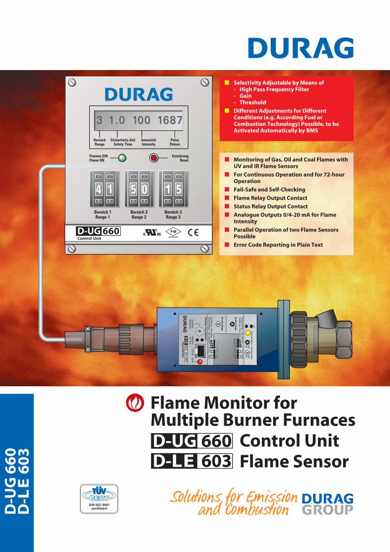
Flame Monitor forMultiple Burner Furnaces
Control UnitFlame Sensor
D-UG 660D-LE 603
■ Monitoring of Gas, Oil and Coal Flames withUV and IR Flame Sensors
■ For Continuous Operation and for 72-hourOperation
■ Fail-Safe and Self-Checking
■ Flame Relay Output Contact
■ Status Relay Output Contact
■ Analogue Outputs 0/4-20 mA for FlameIntensity
■ Parallel Operation of two Flame SensorsPossible
■ Error Code Reporting in Plain Text
■ Selectivity Adjustable by Means of- High Pass Frequency Filter- Gain - Threshold
■ Different Adjustments for DifferentConditions (e.g. According Fuel orCombustion Technology) Possible, to beActivated Automatically by BMS
D-UG 660 / D-LE 603
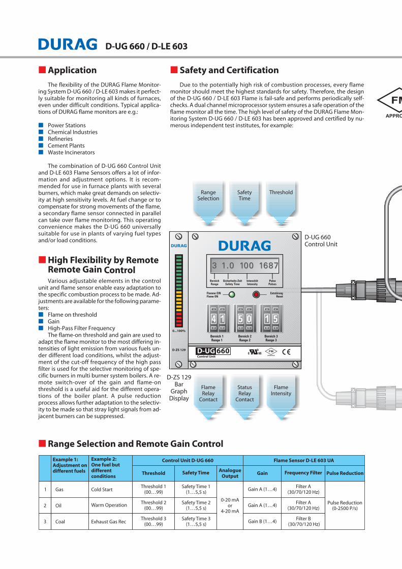
■ Application
The flexibility of the DURAG Flame Monitor-ing System D-UG 660 / D-LE 603 makes it perfect-ly suitable for monitoring all kinds of furnaces,even under difficult conditions. Typical applica-tions of DURAG flame monitors are e.g.:
■ Power Stations■ Chemical Industries■ Refineries■ Cement Plants■ Waste Incinerators
The combination of D-UG 660 Control Unitand D-LE 603 Flame Sensors offers a lot of infor-mation and adjustment options. It is recom-mended for use in furnace plants with severalburners, which make great demands on selectiv-ity at high sensitivity levels. At fuel change or tocompensate for strong movements of the flame,a secondary flame sensor connected in parallelcan take over flame monitoring. This operatingconvenience makes the D-UG 660 universallysuitable for use in plants of varying fuel typesand/or load conditions.
■ High Flexibility by RemoteRemote Gain ControlVarious adjustable elements in the control
unit and flame sensor enable easy adaptation tothe specific combustion process to be made. Ad-justments are available for the following parame-ters:■ Flame on threshold■ Gain■ High-Pass Filter Frequency
The flame-on threshold and gain are used toadapt the flame monitor to the most differing in-tensities of light emission from various fuels un-der different load conditions, whilst the adjust-ment of the cut-off frequency of the high passfilter is used for the selective monitoring of spe-cific burners in multi burner system boilers. A re-mote switch-over of the gain and flame-onthreshold is a useful aid for the different opera-tions of the boiler plant. A pulse reductionprocess allows further adaptation to the selectiv-ity to be made so that stray light signals from ad-jacent burners can be suppressed.
■ Safety and Certification
Due to the potentially high risk of combustion processes, every flamemonitor should meet the highest standards for safety. Therefore, the designof the D-UG 660 / D-LE 603 Flame is fail-safe and performs periodically self-checks. A dual channel microprocessor system ensures a safe operation of theflame monitor all the time. The high level of safety of the DURAG Flame Mon-itoring System D-UG 660 / D-LE 603 has been approved and certified by nu-merous independent test institutes, for example:
■ Range Selection and Remote Gain Control
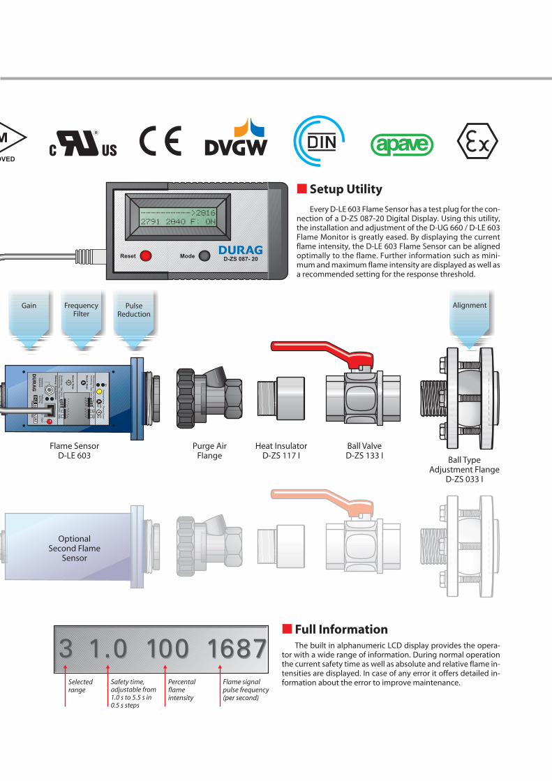
■ Setup Utility
Every D-LE 603 Flame Sensor has a test plug for the con-nection of a D-ZS 087-20 Digital Display. Using this utility,the installation and adjustment of the D-UG 660 / D-LE 603Flame Monitor is greatly eased. By displaying the currentflame intensity, the D-LE 603 Flame Sensor can be alignedoptimally to the flame. Further information such as mini-mum and maximum flame intensity are displayed as well asa recommended setting for the response threshold.
■ Full InformationThe built in alphanumeric LCD display provides the opera-
tor with a wide range of information. During normal operationthe current safety time as well as absolute and relative flame in-tensities are displayed. In case of any error it offers detailed in-formation about the error to improve maintenance.
D-UG 660 / D-LE 603
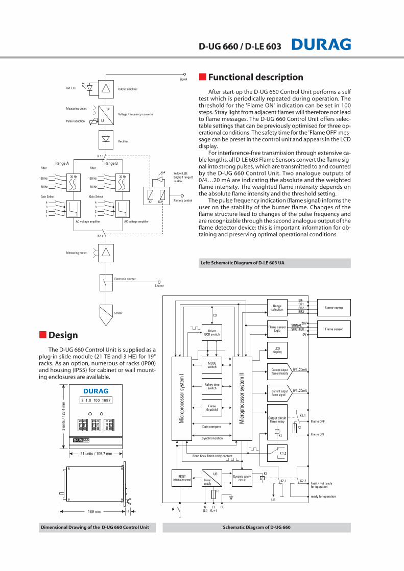
■ Functional description
After start-up the D-UG 660 Control Unit performs a selftest which is periodically repeated during operation. Thethreshold for the 'Flame ON' indication can be set in 100steps. Stray light from adjacent flames will therefore not leadto flame messages. The D-UG 660 Control Unit offers selec-table settings that can be previously optimised for three op-erational conditions. The safety time for the 'Flame OFF' mes-sage can be preset in the control unit and appears in the LCDdisplay.
For interference-free transmission through extensive ca-ble lengths, all D-LE 603 Flame Sensors convert the flame sig-nal into strong pulses, which are transmitted to and countedby the D-UG 660 Control Unit. Two analogue outputs of0/4…20 mA are indicating the absolute and the weightedflame intensity. The weighted flame intensity depends onthe absolute flame intensity and the threshold setting.
The pulse frequency indication (flame signal) informs theuser on the stability of the burner flame. Changes of theflame structure lead to changes of the pulse frequency andare recognizable through the second analogue output of theflame detector device: this is important information for ob-taining and preserving optimal operational conditions.
■ Design
The D-UG 660 Control Unit is supplied as aplug-in slide module (21 TE and 3 HE) for 19"racks. As an option, numerous of racks (IP00)and housing (IP55) for cabinet or wall mount-ing enclosures are available.
Dimensional Drawing of the D-UG 660 Control Unit Schematic Diagram of D-UG 660
Left: Schematic Diagram of D-LE 603 UA
D-UG 660 / D-LE 603
Photo Element
High voltage UV cell
Plate UV cell
GaP with UV-filter
GaP without UV-filter
Si
Ge
Si 4 quadrant
Si 4 quadrant
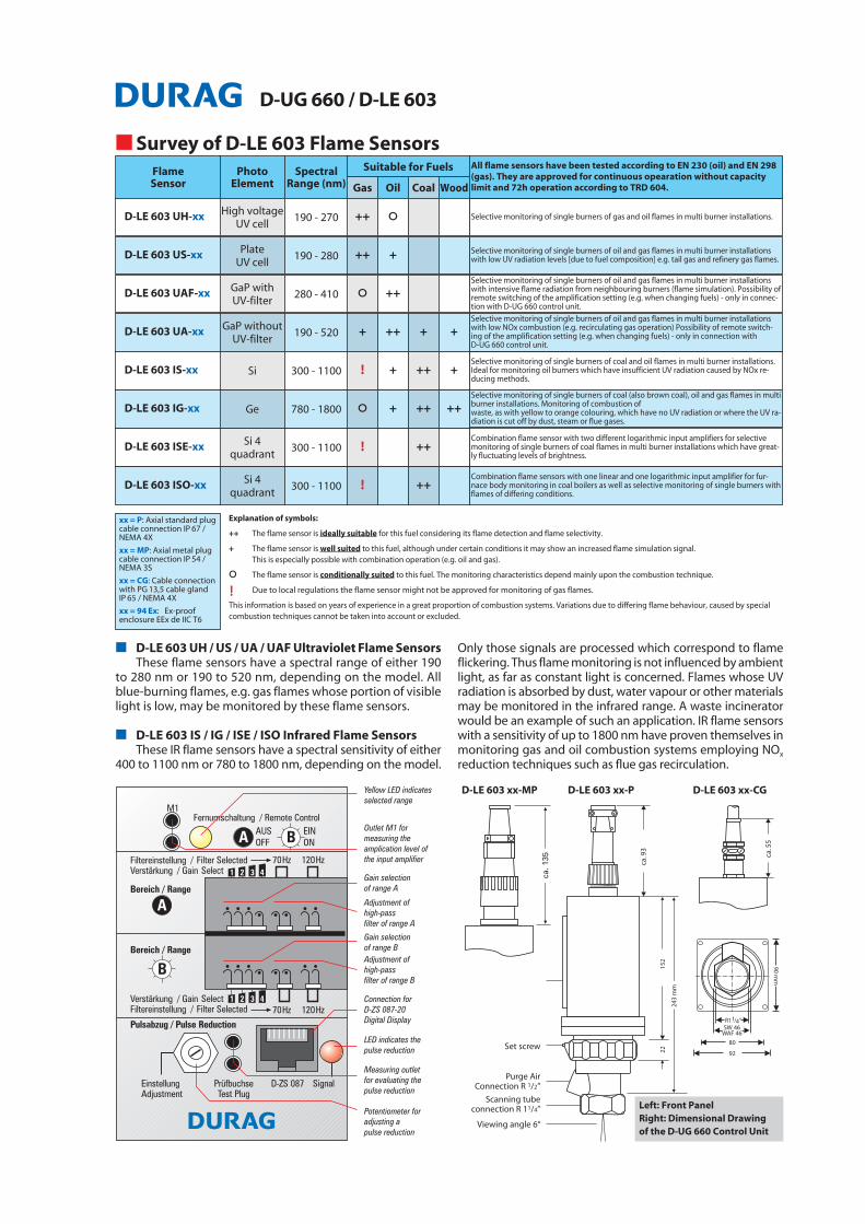
■■ D-LE 603 UH / US / UA / UAF Ultraviolet Flame Sensors These flame sensors have a spectral range of either 190
to 280 nm or 190 to 520 nm, depending on the model. Allblue-burning flames, e.g. gas flames whose portion of visiblelight is low, may be monitored by these flame sensors.
■■ D-LE 603 IS / IG / ISE / ISO Infrared Flame SensorsThese IR flame sensors have a spectral sensitivity of either
400 to 1100 nm or 780 to 1800 nm, depending on the model.
Only those signals are processed which correspond to flameflickering. Thus flame monitoring is not influenced by ambientlight, as far as constant light is concerned. Flames whose UVradiation is absorbed by dust, water vapour or other materialsmay be monitored in the infrared range. A waste incineratorwould be an example of such an application. IR flame sensorswith a sensitivity of up to 1800 nm have proven themselves inmonitoring gas and oil combustion systems employing NOx
reduction techniques such as flue gas recirculation.
Selective monitoring of single burners of gas and oil flames in multi burner installations.
Selective monitoring of single burners of oil and gas flames in multi burner installationswith low UV radiation levels [due to fuel composition] e.g. tail gas and refinery gas flames.
Selective monitoring of single burners of oil and gas flames in multi burner installationswith intensive flame radiation from neighbouring burners (flame simulation). Possibility ofremote switching of the amplification setting (e.g. when changing fuels) - only in connec-tion with D-UG 660 control unit.
Selective monitoring of single burners of coal and oil flames in multi burner installations.Ideal for monitoring oil burners which have insufficient UV radiation caused by NOx re-ducing methods.
Selective monitoring of single burners of coal (also brown coal), oil and gas flames in multiburner installations. Monitoring of combustion of waste, as with yellow to orange colouring, which have no UV radiation or where the UV ra-diation is cut off by dust, steam or flue gases.
Combination flame sensor with two different logarithmic input amplifiers for selectivemonitoring of single burners of coal flames in multi burner installations which have great-ly fluctuating levels of brightness.
Combination flame sensors with one linear and one logarithmic input amplifier for fur-nace body monitoring in coal boilers as well as selective monitoring of single burners withflames of differing conditions.
Selective monitoring of single burners of oil and gas flames in multi burner installationswith low NOx combustion (e.g. recirculating gas operation) Possibility of remote switch-ing of the amplification setting (e.g. when changing fuels) - only in connection withD-UG 660 control unit.
Spectral Range (nm)
190 - 270
190 - 280
280 - 410
190 - 520
300 - 1100
780 - 1800
300 - 1100
300 - 1100
Gas Oil Coal Wood
++ O
++ +
O ++
+ ++ + +
! + ++ +
O + ++ ++
! ++
! ++
Flame Sensor
D-LE 603 UH-xx
D-LE 603 US-xx
D-LE 603 UAF-xx
D-LE 603 UA-xx
D-LE 603 IS-xx
D-LE 603 IG-xx
D-LE 603 ISE-xx
D-LE 603 ISO-xx
Left: Front Panel Right: Dimensional Drawing of the D-UG 660 Control Unit
Suitable for Fuels All flame sensors have been tested according to EN 230 (oil) and EN 298(gas). They are approved for continuous opearation without capacitylimit and 72h operation according to TRD 604.
■■ Survey of D-LE 603 Flame Sensors
Explanation of symbols:
++ The flame sensor is ideally suitable for this fuel considering its flame detection and flame selectivity.
+ The flame sensor is well suited to this fuel, although under certain conditions it may show an increased flame simulation signal. This is especially possible with combination operation (e.g. oil and gas).
O The flame sensor is conditionally suited to this fuel. The monitoring characteristics depend mainly upon the combustion technique.
! Due to local regulations the flame sensor might not be approved for monitoring of gas flames.
This information is based on years of experience in a great proportion of combustion systems. Variations due to differing flame behaviour, caused by specialcombustion techniques cannot be taken into account or excluded.
xx = P: Axial standard plugcable connection IP 67 /NEMA 4X
xx = MP: Axial metal plugcable connection IP 54 /NEMA 3S
xx = CG: Cable connectionwith PG 13,5 cable gland IP 65 / NEMA 4X
xx = 94 Ex: Ex-proofenclosure EEx de IIC T6
D-U
G 6
60
D- L
E6
03
www.durag.de 05/2001 - All specifications subject to change without notice
DURAG Industrie Elektronik GmbH & Co KG
Kollaustr. 105D-22453 Hamburg, Germany
Tel. +49 40 55 42 18-0Fax +49 40 58 41 54
Georg Hegwein GmbH & Co. KGAm Boschwerk 7
D-70469 Stuttgart, GermanyTel. +49 711 13 57 88-0Fax+49 711 13 57 88-5
VEREWA Umwelt- und Prozessmesstechnik GmbH
Kollaustr. 105D-22453 Hamburg, Germany
Tel. +49 40 55 42 18-0Fax +49 40 58 41 54
ORFEUS Combustion Engineering GmbH
An der Pönt 53aD-40885 Ratingen, Germany
Tel. +49 2102 9974-0Fax +49 2102 9974-41
DURAG, Inc.1970 Christensen Ave.West St. Paul, MN 55118
USATel. +1 651 451-1710Fax +1 651 457-7684
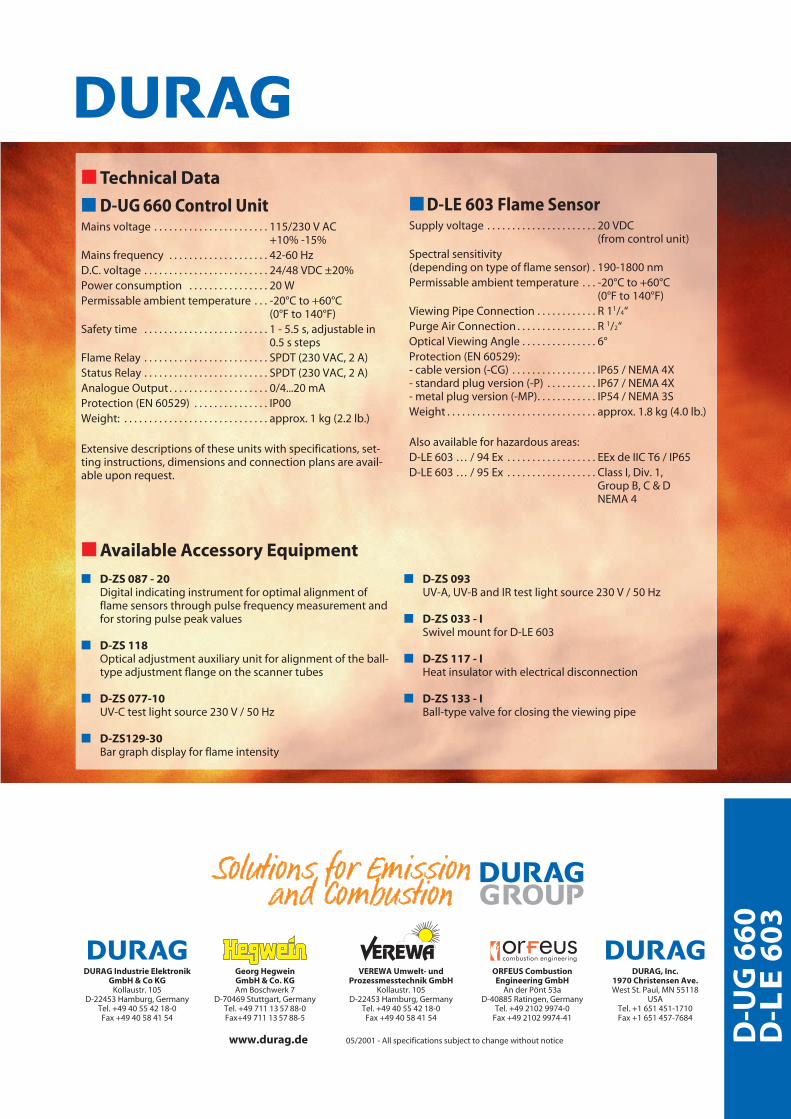
■■ Technical Data
■ D-UG 660 Control Unit Mains voltage . . . . . . . . . . . . . . . . . . . . . . . 115/230 V AC
+10% -15%Mains frequency . . . . . . . . . . . . . . . . . . . . 42-60 HzD.C. voltage . . . . . . . . . . . . . . . . . . . . . . . . . 24/48 VDC ±20%Power consumption . . . . . . . . . . . . . . . . 20 WPermissable ambient temperature . . . -20°C to +60°C
(0°F to 140°F)Safety time . . . . . . . . . . . . . . . . . . . . . . . . . 1 - 5.5 s, adjustable in
0.5 s stepsFlame Relay . . . . . . . . . . . . . . . . . . . . . . . . . SPDT (230 VAC, 2 A)Status Relay . . . . . . . . . . . . . . . . . . . . . . . . . SPDT (230 VAC, 2 A)Analogue Output . . . . . . . . . . . . . . . . . . . . 0/4...20 mAProtection (EN 60529) . . . . . . . . . . . . . . . IP00Weight: . . . . . . . . . . . . . . . . . . . . . . . . . . . . . approx. 1 kg (2.2 lb.)
Extensive descriptions of these units with specifications, set-ting instructions, dimensions and connection plans are avail-able upon request.
■ D-LE 603 Flame Sensor Supply voltage . . . . . . . . . . . . . . . . . . . . . . 20 VDC
(from control unit)Spectral sensitivity (depending on type of flame sensor) . 190-1800 nmPermissable ambient temperature . . . -20°C to +60°C
(0°F to 140°F)Viewing Pipe Connection . . . . . . . . . . . . R 11/4“Purge Air Connection . . . . . . . . . . . . . . . . R 1/2“Optical Viewing Angle . . . . . . . . . . . . . . . 6°Protection (EN 60529):- cable version (-CG) . . . . . . . . . . . . . . . . . IP65 / NEMA 4X- standard plug version (-P) . . . . . . . . . . IP67 / NEMA 4X- metal plug version (-MP). . . . . . . . . . . . IP54 / NEMA 3SWeight . . . . . . . . . . . . . . . . . . . . . . . . . . . . . . approx. 1.8 kg (4.0 lb.)
Also available for hazardous areas:D-LE 603 … / 94 Ex . . . . . . . . . . . . . . . . . . EEx de IIC T6 / IP65D-LE 603 … / 95 Ex . . . . . . . . . . . . . . . . . . Class I, Div. 1,
Group B, C & DNEMA 4
■■ Available Accessory Equipment
■ D-ZS 087 - 20Digital indicating instrument for optimal alignment offlame sensors through pulse frequency measurement andfor storing pulse peak values
■ D-ZS 118Optical adjustment auxiliary unit for alignment of the ball-type adjustment flange on the scanner tubes
■ D-ZS 077-10UV-C test light source 230 V / 50 Hz
■ D-ZS129-30Bar graph display for flame intensity
■ D-ZS 093UV-A, UV-B and IR test light source 230 V / 50 Hz
■ D-ZS 033 - ISwivel mount for D-LE 603
■ D-ZS 117 - IHeat insulator with electrical disconnection
■ D-ZS 133 - IBall-type valve for closing the viewing pipe