Embed Size (px)
Citation preview
FLAME ACCELERATION AND TRANSITION FROM DEFLAGRATION TO DETONATION IN HYDROGEN EXPLOSIONS
A. Heidari and J.X. Wen*
Centre for Fire and Explosion Studies, Faculty of Engineering, Kingston University Friars Avenue, London, SW15 3DW, UK
• Correspondence: j [email protected]
ABSTRACT Computational fluid dynamics based solvers have been developed for explosion modeling in hazards analysis. These include a numerical approach to simulate flame acceleration and deflagration to detonation transition in hydrogen-air mixture and two detonation solvers. The former solves fully compressible, multidimensional, transient, reactive Navier–Stokes equations with a chemical reaction mechanism for different stages of flame propagation and acceleration from a laminar flame to a highly turbulent flame and subsequent transition from deflagration to detonation. The model has been used to simulate flame acceleration (FA) and transition from deflagration to detonation (DDT) in a 2-D symmetric rectangular channel with 0.04 m height and 1 m length which is filled with obstacles. Comparison has been made between the predictions using a 21-step detailed chemistry as well as a single step reaction mechanism. The effect of initial temperature on the run-up distances to DDT has also been investigated.
Comparative study has also been carried out for two detonation solvers. One is based the reactive Euler equations while the other is based on the simpler programmed C-burn method. Comparison has shown that the relatively simple CJ burn approach is unable to capture some very important features of detonation when there are obstacles present in the cloud.
INTRODUCTION
Accidental release of hydrogen can result in a highly reactive mixture with air. Because of its low ignition energy and high laminar flame speed, even a weak ignition of hydrogen-air mixture can lead to rapid flame propagation and acceleration with possible transition to detonation, which is the most destructive type of combustion.
In order to address the related safety issues, the behaviour of accelerating hydrogen flames and the criteria of deflagration to detonation transition (DDT) need to be adequately quantified. The relatively high cost and requirement for specialist facilities have put constraint on the number and physical scale of the experimental tests that can be conducted. Validated predictive tools are increasingly regarded as an alternative for consequence analysis in the development of codes and standards, facility sitting as well as development of mitigation and protection measures.
Lee et al. [1] proposed the well-known SWACER (Sock Wave Amplification through Coherent Energy Release) mechanism. This bears close similarity to the induction time gradient theory developed by Zeldovich in 1970 [2] but offers more physical insight. According to the SWACER mechanism, the formation of detonation requires amplification of shock waves through several localised auto explosions. Based on the synchronisation of shock wave and chemical energy release applied to a single travelling pressure pulse, the SWACER mechanism implies that the time sequence of chemical energy release is coherent with the shock wave it generates and acts to strengthen the propagating shock.
Kratzel et al. [3] conducted 2-dimensional direct numerical simulation of DDT in hydrogen-air mixture in an obstructed tube. In their simulations, flame folding in the early phase of the process following ignition was modelled using large eddy simulation. The predictions were found to be in reasonably good agreement with the experimental data for the actual deflagration and detonation but failed to capture the transition process from deflagration and detonation. Smirnov et al. [4] simulated mixture ignition and flame acceleration in 1-D. They also carried out 2-D detonation modelling with two-step combustion chemistry. A modified Godonov numerical scheme was used to solve the governing equations. The predicted flow structures in the 1-D simulations were found to differ greatly with the change of activation energy (Ea). For high Ea, a region of constant flow was found to follow the combustion wave. For low Ea, a strong (over-driven) detonation wave was initiated following ignition and gradually slowed down to CJ detonation. For intermediate Ea, a turbulent combustion wave was initiated following ignition. This was followed by the gradual increase in the pressure in between the precursor waves and the flame front. The flame accelerated rapidly and underwent transition to detonation. It was postulated that the acceleration of the reaction zone preceded by several shock waves could be a result of the interaction of the contact surface with the flame zone overtaking it [4].
In a brief review of relevant experimental investigations of DDT, Khokhlov and Oran [5] commented that “exactly how DDT occurs is not clear from experiments, and seems to vary from event to event”. They further summarised the earlier experimental observations of other investigators as presenting two basic pictures: sometimes it happened inside the flame brush; sometimes it occurred in the preheated, compressed material between the leading shock wave and the flame brush. Subsequently, they reported a series of numerical simulations of detonation initiation in a flame brush, focusing on the role of hot spots and shock flame interactions [5-7]. Using an in-house physical and numerical model to simulate the shock–flame interaction in the conditions of the reflected shock-tube experiments, they found that the formation of hot spots led to DDT through the gradient mechanism in the region of unburned material between the flame brush and the high-speed shock. The characteristic time of DDT was predicted to be in the order of a microsecond and significantly shorter than the time-scale of the shock–flame interaction itself which is approximately a millisecond. DDT was predicted to appear as a sudden explosion. The appearance of DDT ahead of the flame brush was observed to be in qualitative agreement with what was observed in certain ranges of Mach numbers in the experiments [5]. On the basis of their 10-year theoretical and numerical effort to understand DDT, Oran and Gamezo [8] commented that to simulate DDT from first principles, it is necessary to resolve the relevant scales ranging from the size of the system to the flame thickness, a range that can cover up to 12 orders of magnitude in real systems. This computational challenge resulted in the development of numerical algorithms for solving coupled partial and ordinary differential equations and a new method for adaptive mesh refinement to deal with multi-scale phenomena. To gain insight into how, when, and where DDT occurs, they carried out a series of multidimensional numerical simulations of laboratory experiments designed to create a turbulent flame through a series of shock–flame interactions. It was found that these interactions are important for creating the conditions in which DDT could occur. The flames would enhance the strength of shocks passing through a turbulent flame brush and generate new shocks. In turn, shock interactions with the flames would create and drive the turbulence in the flames. Their analysis suggested that the turbulent flame itself does not undergo a transition, but it creates conditions in nearby un-reacted material that would lead to ignition centres, or “hot spots” which can then produce a detonation through the Zeldovich gradient mechanism involving gradients of reactivity. Obstacles and boundary layers, through their interactions with shocks and flames, were found to promote conditions in which hot spots could develop. Other scenarios producing reactivity gradients that can lead to DDT were found to include flame–flame interactions, turbulent mixing of hot products with reactant gases, and direct shock ignition. Vaagsaether et al. [9] simulated flame acceleration and DDT in a hydrogen air mixture with a code based on flux limiter centred method for hyperbolic partial differential equations. They calculated the energy source term by a Riemann solver for the inhomogeneous Euler equations for the turbulent
combustion and a two step reaction model for hydrogen-air reaction. However, it was unclear whether the physics of DDT was addressed in the numerical model or it simply used some “numerical switch” to trigger DDT in the simulations.
In the present study, numerical approaches have been developed to simulate flame acceleration and DDT in a hydrogen-air mixture as well as hydrogen detonation.
GOVERNING EQUATIONS FOR DDT SOLVER
Numerical simulations of the DDT process need to address a wide range of combustion regimes from laminar flame up to detonations. Hence a full Navier-Stokes equations solver is required. These equations show the conservation of mass, momentum and energy:
Mass conservation equation:
���� � ���ρ (1)
Momentum conservation equation:
���� � ���ρ � �P � �τ (2)
Energy conservation equation:
����� � ����E � P � ��τ � ��K��T� � ρqω� (3)
Spices conservation equation:
����� � ���ρY � ��ρD�Y � ��K��T� � ρω� (4)
where ρ is the mass density, V is the velocity, E is the energy density, P is the pressure, Y is the mass fraction of a reactant, K is the thermal conduction coefficient, D is the mass diffusion coefficient and ω� is the reaction source term, and τ is the viscous stress tensor which includes terms arising in compressible Navier-Stokes equations with zero bulk viscosity. The above equations should be solved along with a proper set of chemical reaction equations to model the consumption and production of each chemical element which is present during the detonation process. By using the rate of production and consumption of each element and the resulting change in the enthalpy it is possible to calculate the energy source term and the progress rate of the flame.
For the chemistry, Williams’ [13] 21-step hydrogen autoignition mechanism as well as a single step reaction mechanism are used. Details of the 21-step scheme can be found in reference [13] while the Arrhenius source term used for the single step reaction was taken from Gamezo et al. [10]:
ω� � 6.85 10#$ exp (� ##$)*# +, - (5)
The governing equations are solved using finite volume discretization. An implicit Euler time discretization as well as a total variation diminishing scheme are used for shock capturing. In order to handle the stiffness when using the detailed mechanism, a more stable implicit method is used while the time steps are kept very small with the Courant number being kept at around 0.01.
For model validations, Both one- and two-dimensional were carried out to verify that the model predicts the right laminar flame speed for laminar hydrogen-air flame and the predictions were found to compare favourably with the experimental measurements [16].
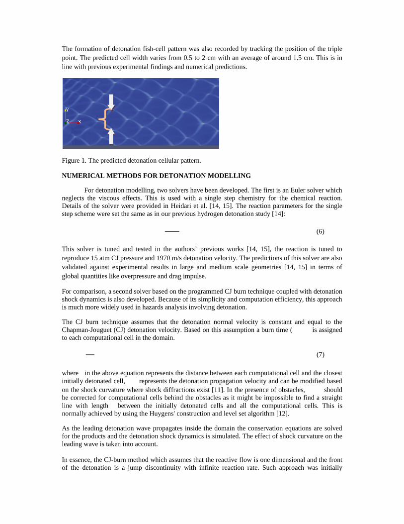
The formation of detonation fish-cell pattern was also recorded by tracking the position of the triple point. The predicted cell width varies from 0.5 to 2 cm with an average of around 1.5 cm. This is in line with previous experimental findings and numerical predictions.
Figure 1. The predicted detonation cellular pattern.
NUMERICAL METHODS FOR DETONATION MODELLING
For detonation modelling, two solvers have been developed. The first is an Euler solver which neglects the viscous effects. This is used with a single step chemistry for the chemical reaction. Details of the solver were provided in Heidari et al. [14, 15]. The reaction parameters for the single step scheme were set the same as in our previous hydrogen detonation study [14]:
(6)
This solver is tuned and tested in the authors’ previous works [14, 15], the reaction is tuned to reproduce 15 atm CJ pressure and 1970 m/s detonation velocity. The predictions of this solver are also validated against experimental results in large and medium scale geometries [14, 15] in terms of global quantities like overpressure and drag impulse.
For comparison, a second solver based on the programmed CJ burn technique coupled with detonation shock dynamics is also developed. Because of its simplicity and computation efficiency, this approach is much more widely used in hazards analysis involving detonation.
The CJ burn technique assumes that the detonation normal velocity is constant and equal to the Chapman-Jouguet (CJ) detonation velocity. Based on this assumption a burn time ( is assigned to each computational cell in the domain.
(7)
where in the above equation represents the distance between each computational cell and the closest initially detonated cell, represents the detonation propagation velocity and can be modified based on the shock curvature where shock diffractions exist [11]. In the presence of obstacles, should be corrected for computational cells behind the obstacles as it might be impossible to find a straight line with length between the initially detonated cells and all the computational cells. This is normally achieved by using the Huygens' construction and level set algorithm [12].
As the leading detonation wave propagates inside the domain the conservation equations are solved for the products and the detonation shock dynamics is simulated. The effect of shock curvature on the leading wave is taken into account. In essence, the CJ-burn method which assumes that the reactive flow is one dimensional and the front of the detonation is a jump discontinuity with infinite reaction rate. Such approach was initially
developed for simulating blast waves resulted from solid explosives. Even if the subsequent improvement of the method has allowed the 3-dimensional fluid dynamics to be imposed on the blast wave, it misses out important characteristics of the fully three–dimensional vapour cloud detonation. This approach will not be able to capture the deviation of detonation pressure and velocity in complex geometries and in the presence of obstacles where the reflected shocks need to be taken into consideration. Since the shortcomings of CJ-Burn method can be demonstrated better in the domains with obstacles, a sample vapour cloud with 6 obstacles of different size is chosen as the test case to compare the two detonation simulation method. Figure 6 shows the numerical domain for detonation simulations in which the obstacles are numbered for easy referencing.
NUMERICAL SIMULATIONS OF DDT IN A SMALL OBSTRUCTED TUBE
Preliminary numerical tests have been conducted to verify the accuracy of the predicted flame temperature and velocity as well as detonation pressure, velocity and cell size. On this basis, numerical simulations have been carried out for hydrogen DDT in a small obstructed tube which is essentially the same as that in the DDT simulations of Oran et al. [10]. It consists of a tube 2 cm high (half size of the actual domain is modelled because of symmetry) and 1 m long. The tube is filled with obstacles with the same height of 1 cm. The distance between two consecutive obstacles is 4 cm. A schematic of the computational domain is shown in Figure 2.
Figure 2. Schematic of the numerical domain
A structured grid with a minimum size of about 10-20 ./ is used. The left side of the tube is closed while the right side is open. No-slip reflecting boundary condition is used for the walls and a symmetry boundary condition is used so only half of the domain needs to be computed.
The reactive gas is stoichiometric hydrogen-air mixture at 1 atm. The ignition is triggered by an initial circular hot (2000 K) burned mixture region as shown in Figure 2.
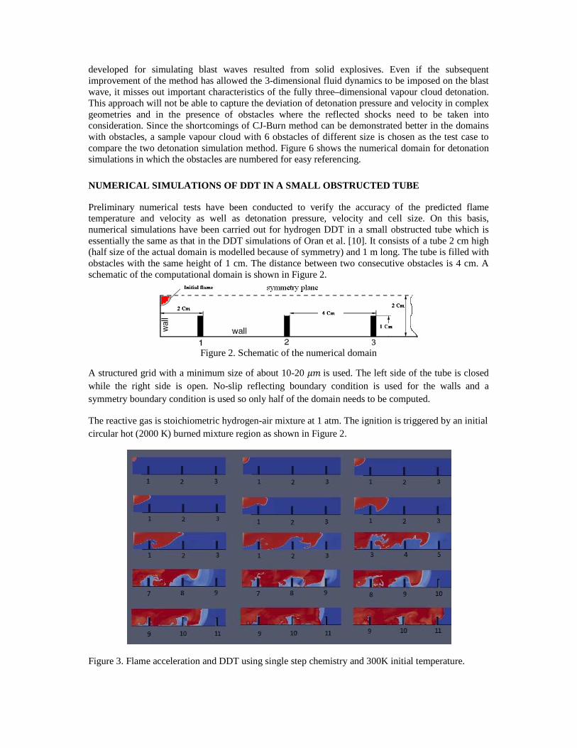
Figure 3. Flame acceleration and DDT using single step chemistry and 300K initial temperature.
Three set of simulations were conducted to compare the effect of chemistry and initial temperature. These include predictions for single step chemistry and 300 K initial temperature, 21-step chemistry and 300 K initial temperature as well as 21-step chemistry and 293 K initial temperature. Single Step Chemistry and 300 K Initial Temperature
The predicted flame propagation and acceleration are illustrated in 15 frames in Figure 3. Following ignition, a laminar flame starts to propagate from the initial ignition centre towards the first obstacle. Initially, the flame propagates at the hydrogen laminar burning velocity which is about 3 m/s.
Gradually, the flame front starts to accelerate as the expansion of hot gases behind the flame pushes the flame front further away from the left side of the tube. The flame starts to wrinkle and accelerate further after it passes over the first obstacle. In the 9th frame, the flame front, which is right after the 4th obstacle, appears to be highly distorted. The increase in the flame surface area increases the rate of energy release which leads to further acceleration of the flame. After the flame passes the 6th obstacle, the rate of energy release is so high that it generates several pressure waves ahead of the flame. The 10th frame shows the flame passing over the 8th obstacle and several clear pressure waves moving ahead of the flame. The 11th frame shows a reflected pressure wave from the 9th obstacle hitting the flame front. As the flame accelerates further, more pressure waves are generated ahead of the flame. These pressure waves catch up with the leading pressure wave and further amplify it. Finally, the reflection of a strong leading pressure wave from the 11th obstacle hits the flame front which is moving at high velocity in the vicinity of the leading wave. The flame-shock interaction generates a hot spot or a strong localised explosion slightly before the 11th obstacle. The high velocity deflagration wave undergoes transition to detonation right before the 11th obstacle. From this point onwards, the leading shock wave and the combustion region are coupled and moving together at a local velocity of about 1990 m/s.
21 Step Chemistry and 300K Initial Temperature
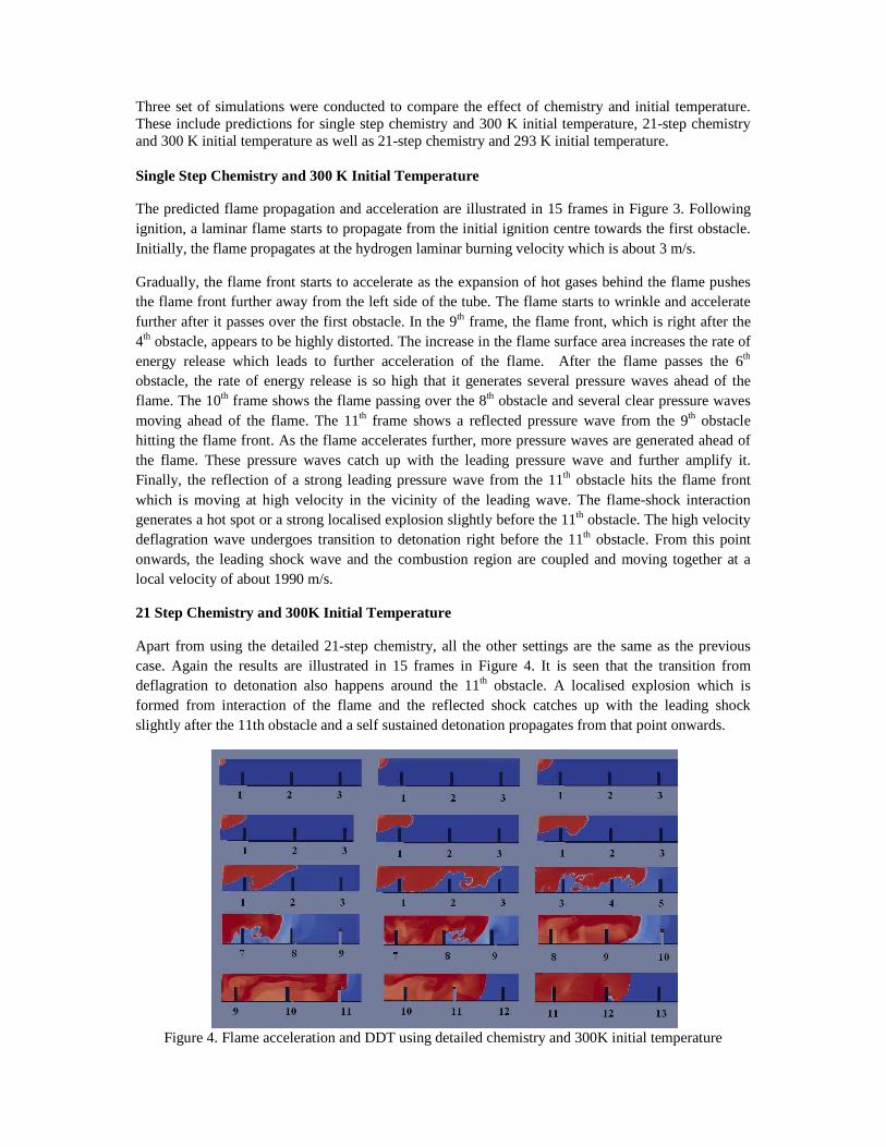
Apart from using the detailed 21-step chemistry, all the other settings are the same as the previous case. Again the results are illustrated in 15 frames in Figure 4. It is seen that the transition from deflagration to detonation also happens around the 11th obstacle. A localised explosion which is formed from interaction of the flame and the reflected shock catches up with the leading shock slightly after the 11th obstacle and a self sustained detonation propagates from that point onwards.
Figure 4. Flame acceleration and DDT using detailed chemistry and 300K initial temperature
21 Step Chemistry and 293 K Initial Temperature
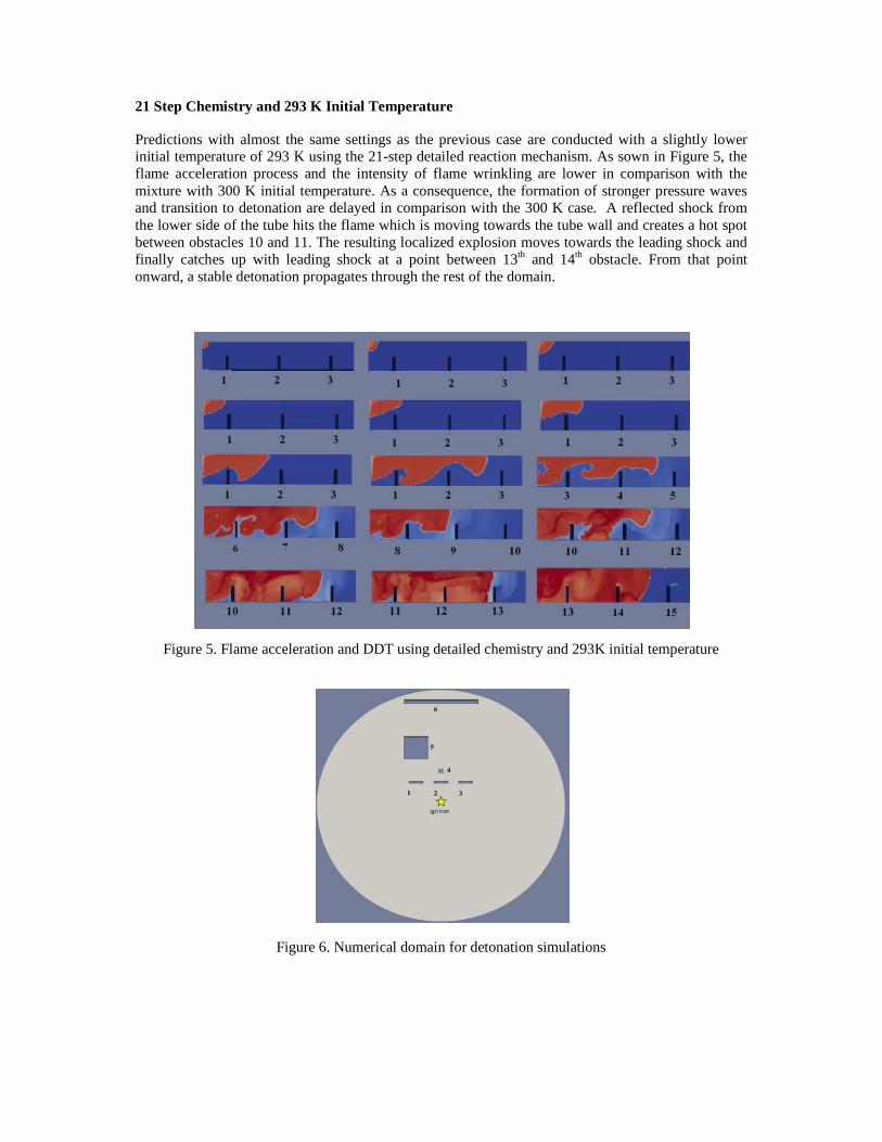
Predictions with almost the same settings as the previous case are conducted with a slightly lower initial temperature of 293 K using the 21-step detailed reaction mechanism. As sown in Figure 5, the flame acceleration process and the intensity of flame wrinkling are lower in comparison with the mixture with 300 K initial temperature. As a consequence, the formation of stronger pressure waves and transition to detonation are delayed in comparison with the 300 K case. A reflected shock from the lower side of the tube hits the flame which is moving towards the tube wall and creates a hot spot between obstacles 10 and 11. The resulting localized explosion moves towards the leading shock and finally catches up with leading shock at a point between 13th and 14th obstacle. From that point onward, a stable detonation propagates through the rest of the domain.
Figure 5. Flame acceleration and DDT using detailed chemistry and 293K initial temperature
Figure 6. Numerical domain for detonation simulations
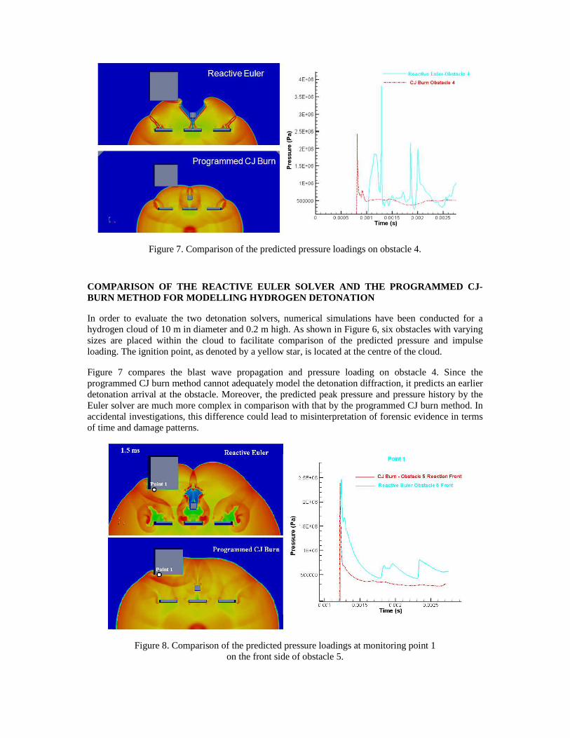
Figure 7. Comparison of the predicted pressure loadings on obstacle 4.
COMPARISON OF THE REACTIVE EULER SOLVER AND THE PRO GRAMMED CJ-BURN METHOD FOR MODELLING HYDROGEN DETONATION
In order to evaluate the two detonation solvers, numerical simulations have been conducted for a hydrogen cloud of 10 m in diameter and 0.2 m high. As shown in Figure 6, six obstacles with varying sizes are placed within the cloud to facilitate comparison of the predicted pressure and impulse loading. The ignition point, as denoted by a yellow star, is located at the centre of the cloud.
Figure 7 compares the blast wave propagation and pressure loading on obstacle 4. Since the programmed CJ burn method cannot adequately model the detonation diffraction, it predicts an earlier detonation arrival at the obstacle. Moreover, the predicted peak pressure and pressure history by the Euler solver are much more complex in comparison with that by the programmed CJ burn method. In accidental investigations, this difference could lead to misinterpretation of forensic evidence in terms of time and damage patterns.
Figure 8. Comparison of the predicted pressure loadings at monitoring point 1 on the front side of obstacle 5.
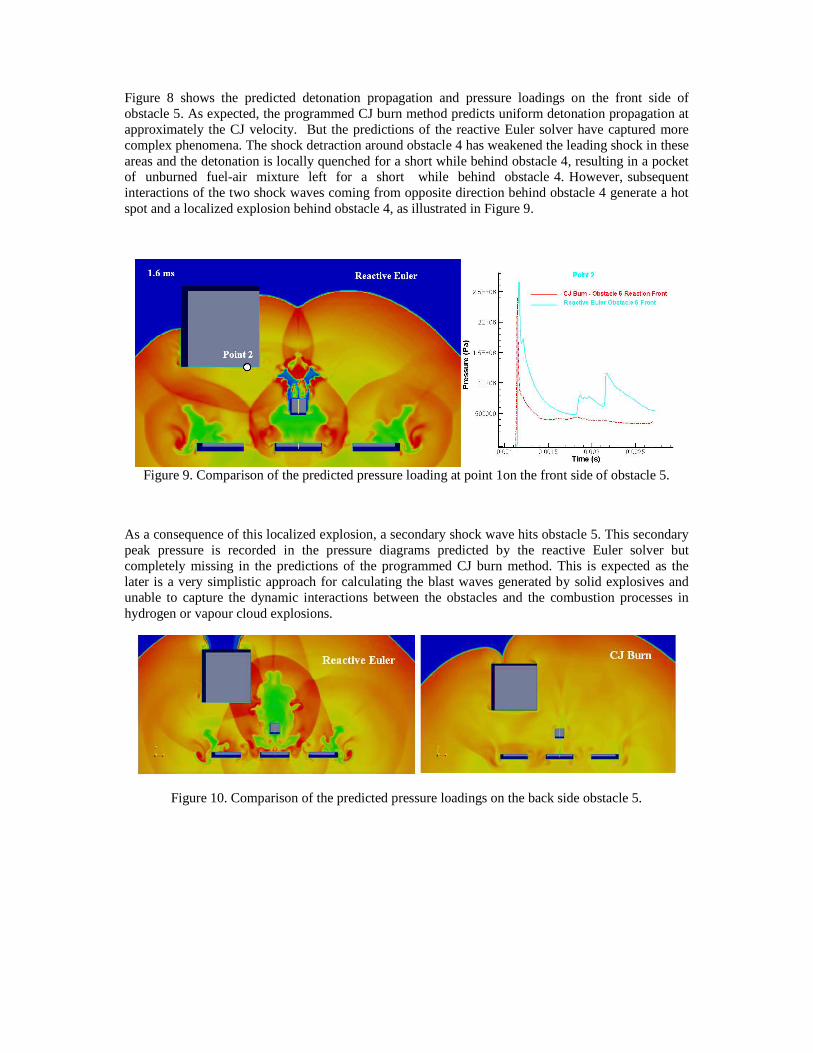
Figure 8 shows the predicted detonation propagation and pressure loadings on the front side of obstacle 5. As expected, the programmed CJ burn method predicts uniform detonation propagation at approximately the CJ velocity. But the predictions of the reactive Euler solver have captured more complex phenomena. The shock detraction around obstacle 4 has weakened the leading shock in these areas and the detonation is locally quenched for a short while behind obstacle 4, resulting in a pocket of unburned fuel-air mixture left for a short while behind obstacle 4. However, subsequent interactions of the two shock waves coming from opposite direction behind obstacle 4 generate a hot spot and a localized explosion behind obstacle 4, as illustrated in Figure 9.
Figure 9. Comparison of the predicted pressure loading at point 1on the front side of obstacle 5.
As a consequence of this localized explosion, a secondary shock wave hits obstacle 5. This secondary peak pressure is recorded in the pressure diagrams predicted by the reactive Euler solver but completely missing in the predictions of the programmed CJ burn method. This is expected as the later is a very simplistic approach for calculating the blast waves generated by solid explosives and unable to capture the dynamic interactions between the obstacles and the combustion processes in hydrogen or vapour cloud explosions.
Figure 10. Comparison of the predicted pressure loadings on the back side obstacle 5.
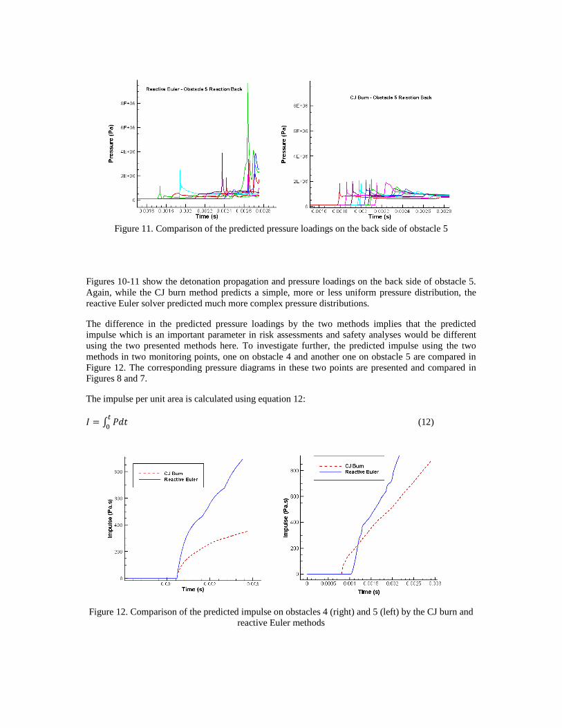
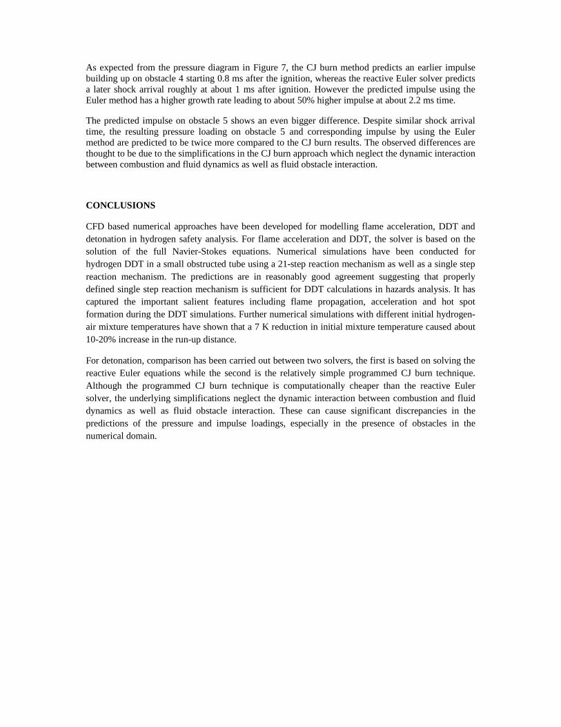
Figure 11. Comparison of the predicted pressure loadings on the back side of obstacle 5
Figures 10-11 show the detonation propagation and pressure loadings on the back side of obstacle 5. Again, while the CJ burn method predicts a simple, more or less uniform pressure distribution, the reactive Euler solver predicted much more complex pressure distributions.
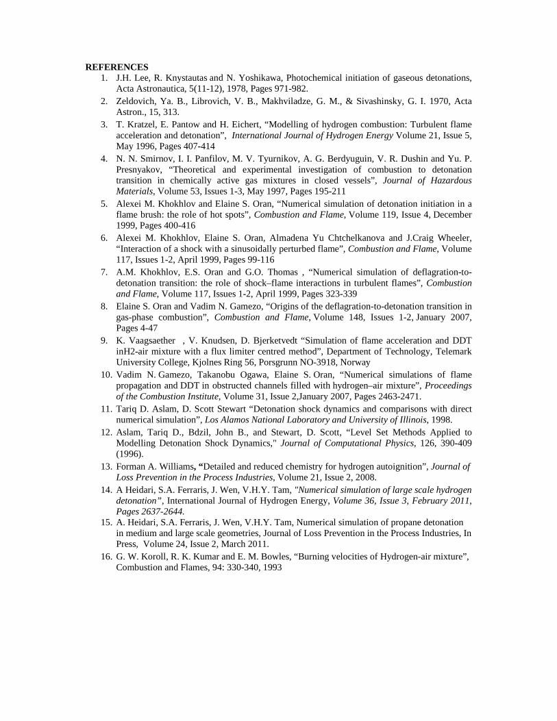
The difference in the predicted pressure loadings by the two methods implies that the predicted impulse which is an important parameter in risk assessments and safety analyses would be different using the two presented methods here. To investigate further, the predicted impulse using the two methods in two monitoring points, one on obstacle 4 and another one on obstacle 5 are compared in Figure 12. The corresponding pressure diagrams in these two points are presented and compared in Figures 8 and 7.
The impulse per unit area is calculated using equation 12:
0 � 1 23456 (12)
Figure 12. Comparison of the predicted impulse on obstacles 4 (right) and 5 (left) by the CJ burn and reactive Euler methods
As expected from the pressure diagram in Figure 7, the CJ burn method predicts an earlier impulse building up on obstacle 4 starting 0.8 ms after the ignition, whereas the reactive Euler solver predicts a later shock arrival roughly at about 1 ms after ignition. However the predicted impulse using the Euler method has a higher growth rate leading to about 50% higher impulse at about 2.2 ms time.
The predicted impulse on obstacle 5 shows an even bigger difference. Despite similar shock arrival time, the resulting pressure loading on obstacle 5 and corresponding impulse by using the Euler method are predicted to be twice more compared to the CJ burn results. The observed differences are thought to be due to the simplifications in the CJ burn approach which neglect the dynamic interaction between combustion and fluid dynamics as well as fluid obstacle interaction.
CONCLUSIONS
CFD based numerical approaches have been developed for modelling flame acceleration, DDT and detonation in hydrogen safety analysis. For flame acceleration and DDT, the solver is based on the solution of the full Navier-Stokes equations. Numerical simulations have been conducted for hydrogen DDT in a small obstructed tube using a 21-step reaction mechanism as well as a single step reaction mechanism. The predictions are in reasonably good agreement suggesting that properly defined single step reaction mechanism is sufficient for DDT calculations in hazards analysis. It has captured the important salient features including flame propagation, acceleration and hot spot formation during the DDT simulations. Further numerical simulations with different initial hydrogen-air mixture temperatures have shown that a 7 K reduction in initial mixture temperature caused about 10-20% increase in the run-up distance.
For detonation, comparison has been carried out between two solvers, the first is based on solving the reactive Euler equations while the second is the relatively simple programmed CJ burn technique. Although the programmed CJ burn technique is computationally cheaper than the reactive Euler solver, the underlying simplifications neglect the dynamic interaction between combustion and fluid dynamics as well as fluid obstacle interaction. These can cause significant discrepancies in the predictions of the pressure and impulse loadings, especially in the presence of obstacles in the numerical domain.
REFERENCES 1. J.H. Lee, R. Knystautas and N. Yoshikawa, Photochemical initiation of gaseous detonations,
Acta Astronautica, 5(11-12), 1978, Pages 971-982. 2. Zeldovich, Ya. B., Librovich, V. B., Makhviladze, G. M., & Sivashinsky, G. I. 1970, Acta
Astron., 15, 313. 3. T. Kratzel, E. Pantow and H. Eichert, “Modelling of hydrogen combustion: Turbulent flame
acceleration and detonation”, International Journal of Hydrogen Energy Volume 21, Issue 5, May 1996, Pages 407-414
4. N. N. Smirnov, I. I. Panfilov, M. V. Tyurnikov, A. G. Berdyuguin, V. R. Dushin and Yu. P. Presnyakov, “Theoretical and experimental investigation of combustion to detonation transition in chemically active gas mixtures in closed vessels”, Journal of Hazardous Materials, Volume 53, Issues 1-3, May 1997, Pages 195-211
5. Alexei M. Khokhlov and Elaine S. Oran, “Numerical simulation of detonation initiation in a flame brush: the role of hot spots”, Combustion and Flame, Volume 119, Issue 4, December 1999, Pages 400-416
6. Alexei M. Khokhlov, Elaine S. Oran, Almadena Yu Chtchelkanova and J.Craig Wheeler, “Interaction of a shock with a sinusoidally perturbed flame”, Combustion and Flame, Volume 117, Issues 1-2, April 1999, Pages 99-116
7. A.M. Khokhlov, E.S. Oran and G.O. Thomas , “Numerical simulation of deflagration-to-detonation transition: the role of shock–flame interactions in turbulent flames”, Combustion and Flame, Volume 117, Issues 1-2, April 1999, Pages 323-339
8. Elaine S. Oran and Vadim N. Gamezo, “Origins of the deflagration-to-detonation transition in gas-phase combustion”, Combustion and Flame, Volume 148, Issues 1-2, January 2007, Pages 4-47
9. K. Vaagsaether�, V. Knudsen, D. Bjerketvedt “Simulation of flame acceleration and DDT inH2-air mixture with a flux limiter centred method”, Department of Technology, Telemark University College, Kjolnes Ring 56, Porsgrunn NO-3918, Norway
10. Vadim N. Gamezo, Takanobu Ogawa, Elaine S. Oran, “Numerical simulations of flame propagation and DDT in obstructed channels filled with hydrogen–air mixture”, Proceedings of the Combustion Institute, Volume 31, Issue 2,January 2007, Pages 2463-2471.
11. Tariq D. Aslam, D. Scott Stewart “Detonation shock dynamics and comparisons with direct numerical simulation”, Los Alamos National Laboratory and University of Illinois, 1998.
12. Aslam, Tariq D., Bdzil, John B., and Stewart, D. Scott, “Level Set Methods Applied to Modelling Detonation Shock Dynamics," Journal of Computational Physics, 126, 390-409 (1996).
13. Forman A. Williams, “Detailed and reduced chemistry for hydrogen autoignition”, Journal of Loss Prevention in the Process Industries, Volume 21, Issue 2, 2008.
14. A Heidari, S.A. Ferraris, J. Wen, V.H.Y. Tam, "Numerical simulation of large scale hydrogen detonation”, International Journal of Hydrogen Energy, Volume 36, Issue 3, February 2011, Pages 2637-2644.
15. A. Heidari, S.A. Ferraris, J. Wen, V.H.Y. Tam, Numerical simulation of propane detonation in medium and large scale geometries, Journal of Loss Prevention in the Process Industries, In Press, Volume 24, Issue 2, March 2011.
16. G. W. Koroll, R. K. Kumar and E. M. Bowles, “Burning velocities of Hydrogen-air mixture”, Combustion and Flames, 94: 330-340, 1993