Embed Size (px)
Citation preview

\ '
~ &#~ ex., ('.sA .-7~ ~ -/'/.
COMMONWEALTH OF AUSTRALIA ~ ~ ~/ 2. 2.~-~.)t Il., IS .
'DEPARTMENT OF NATIONAL DEVELOPMENT
BUREAU OF MINERAL RESOURCES, GEOLOGY AND GEOPHYSICS
RECORD No. 196,31171
1 B FEB 1964
FLAGGY CREEK DAM SITE
GEOPHYSICAL SURVEY, KURANDA,
NORTHERN QUEENSLAND 1962
by
E.J. POLAK
, , ~I : ' I :
The information contained in this report has b~en obt~ined 'by the Department of National Development as part of' ihe 'policy of the Commonwealth Government to assist in the exploration and development of mineral resources. It may not be published in any form or used in a company prospectus or statement without the permission in writing of the Director, Bureau of Mineral Resources, Geology and Geophysics.
·IJ
..
•
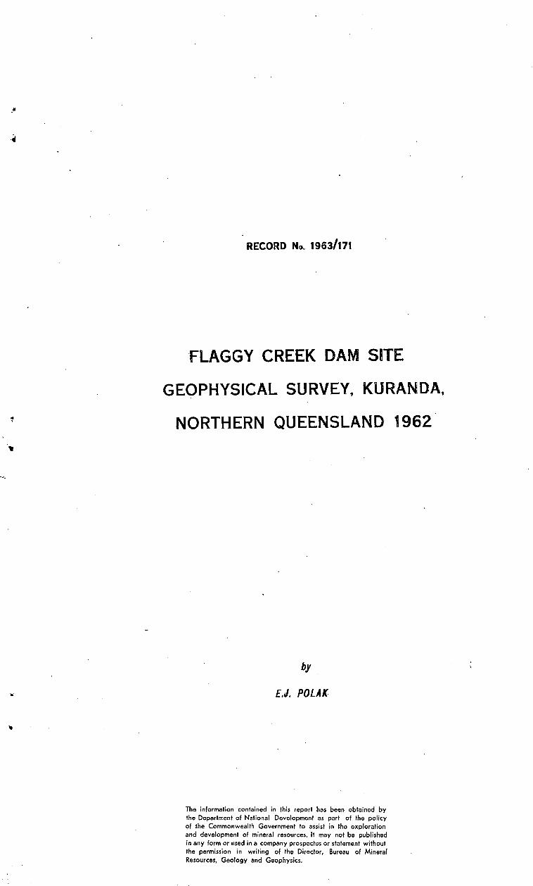
RECORD No. 19631171
FLAGGY CREEK DAM SITE
GEOPHYSICAL SURVEY, KURANDA,
NORTHERN QUEENSLAND 1962
by
E.J. POLAK
The information contained in this report has been obtained by the Department of National Development as part of the policy of the Commonwealth Government to assist in the exploration and development of mineral resources. It may not be published in any form or used in a company prospectus or statement without the permission in writing of the Director, Bureau of Mineral Resources, Geology and Geophysics.

..
'. ..
CONTENTS
;Page
SUMMARY
1 • INTRODUCTION 1
2. GIDLOGY 1
3. MErHODS AJ.lfD EQUIPMENT 2
4· RESULTS 2
5· CONCLUSIONS 6
6. REFERENCES 6
ILLUSTRATIONS
Plate 1. Layout of traverses and locality plan (Drawing lIo. E55/B5-1)
Plate 2. SeiSmic cross-sections and reSistivity profiles on Traverses A and B (E55/B5-2)
Plate 3. SeiSmic cross-sections and reSistivity profiles on Traverses C, D, and E (E55/B5-3)
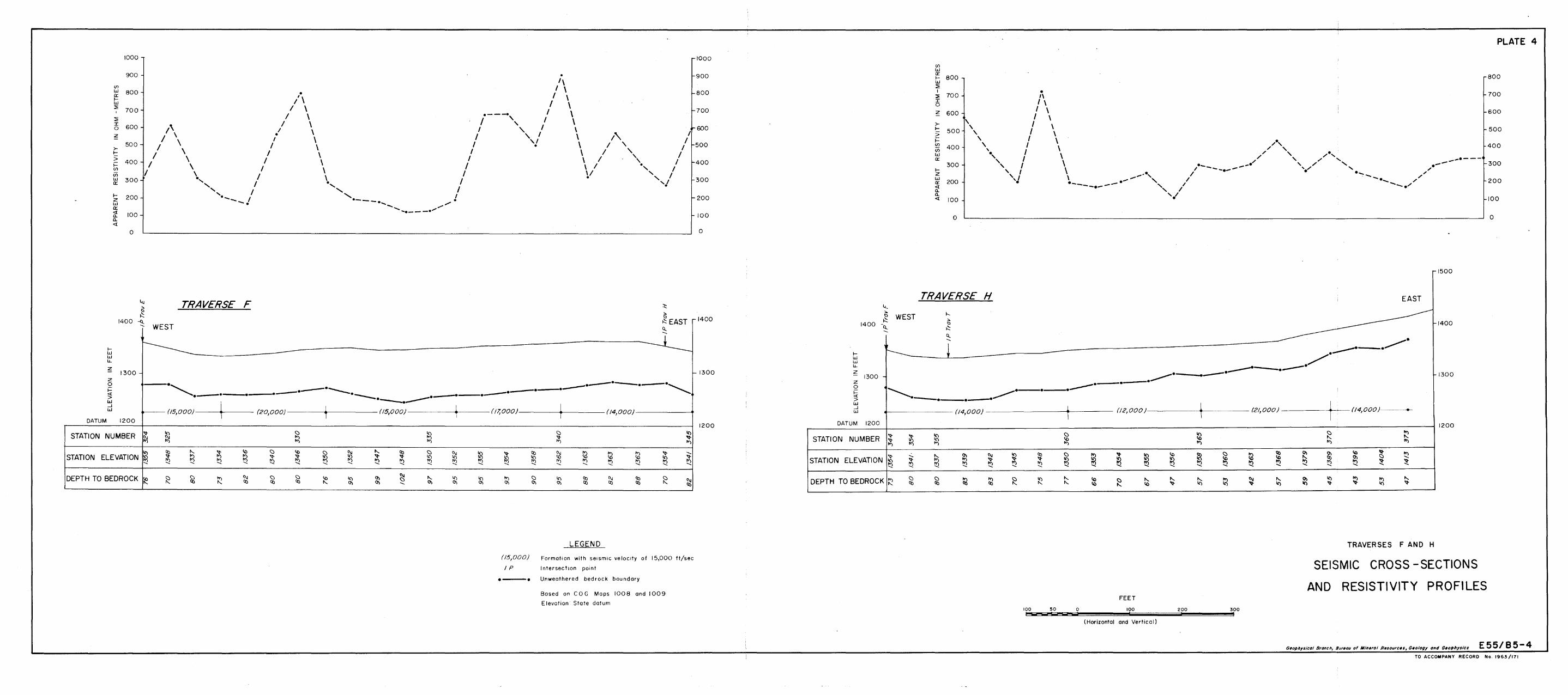
Plate 4. Seismic cross-sections and reSistivity profiles on Traverses F and H (E55/B5-4)
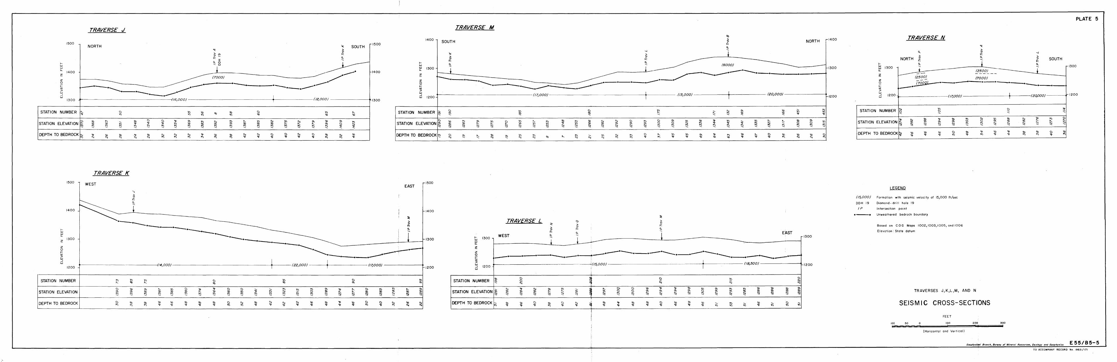
Plate 5. Seismic cross-sections on Traverses J, K, L, M,and N (E55/B5-5)
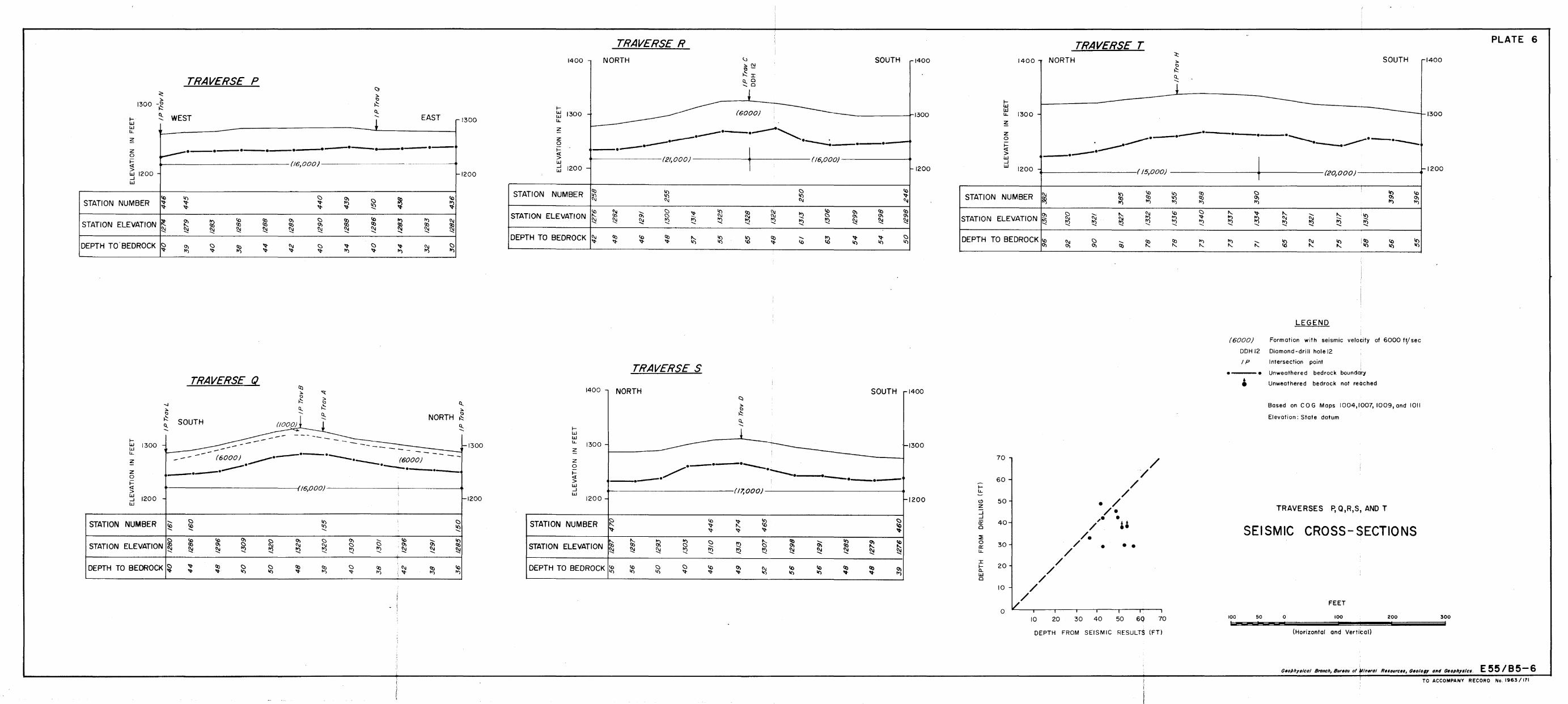
Plate 6. Seismic cross-sections on Traverses P, Q, R, S,and T.(E55/B5-6)
SUMJY[ARY
Details and ref-''J.lts are given of seismic refraction, resist:~ -vitys and mag:.letio surveys that ''lere fficde in response to a request from the GO·-(}l'd:~n.ator GenE;ra~.l s Department, Q;c:.e ensl and , to investigate a propo:o:ed 8i te ior a darn Ot!. Flaggy Creek, near Kuran1a, North l~ue8nsla1:').d.. IJ'he c1aill will be par"!; of the Barron Falls Hydro-Electric Scheme.
The maximum depth to the bedrock was found to be 83 ft .•. Seismic velocities of 8000 to 21,000 ft/sec were recorded in the bedroCk. Poisson's r~tio of 0.33 to 0.35 and Young's modulus of 6.5 x 10⁶ to 9.1 x 10⁶ lb/s~.in. were determined using longitudinal and tr~1sverse ..:aV8 velocities •

..
"
\
1 • INTRODUCTION
The Co-ordinator General's Department for Public Works, Queensland (COG) proposes to construct a dam on the Flaggy Creek, five miles above its junction with the Barron River. The dam is a part of a scheme to provide additional water supply for the Barron Falls Hydro-Electric Station at Kuranda (Polak and Mann, 1959a).
In response to an application from the COG, the. Bureau of Mineral Resources, Geology and Geophysics carried out a geophysicai survey to determine the nature of the overburden and the bedrock and the depth to the bedrock at the dam site and on the ridge separating the proposed reservoir from the lower reaches of the Flaggy Creek valley.
As used in this Record, the term 'bedrock' refers to unweathered, jointed to solid rock in which the velocity of the seismic wave exceeds 10,000 ft/sec. The term 'overburden' refers to river sand and gravels, scree and talus material, and completely to partly weathered rock, in which the seismic velocities are lass than 10,000 ft/sec.
The survey was made in August 1962 by a geophysical party conSisting of E.J. Polak (party leader), J .E.F. Gardener (geophysicist), and J.P. Pigott (geophysical assistant). COG provided additional assistants and carried out a topographical survey along the traverse lines •
2. GEPLOGY
The general geological survey of the area was made by Brooks (1957). Twenty diamond-drill holes and two exploratory shafts were ccmpleted.
The detailed stratigraphy of the area waS given by Polak and Mann (1959a); a short summary (after Brooks) will be given here.
The rocks of the dam site consist of meta-graywacke and slate. The met8,-greywacke is coarser in grain size and more felspathic than the gl'eYVTa~l:::,:) in the Kuranda area. Ifhe slates are better cleaved and the greywacke more noticeably foliated, indicating a higher graci.e of metamorphism tha;.1 in the KlU'anda area. The rocks are heavily jointed, the joints being filled with quartz.
The strike of the cleavage ranges from 315 degrees to 340 degrees,and the dips are usually vertical or 80 degrees to the southwest, or less commonly to the north-east.
The slate and greywacke are impermeable in the unweathered state and the main possible source of leakage would be the major jOints and fauJ.ts. Slightly weathered rock, included in bedrock, should pro'~de sound rock for foundation.
The rock is covered with alluvi urn in the creek valley and with scree and talus material on the ridge.
•
-2-
METHODS AND EQUIPMENT
Seismic refraction, resistivity constant-spacing profiling, and magnetic method~ were used. A detailed description of the methods has been given by Polak and Mann (1959a).
Seismic method
In the calculation of the depth to bedrock the "method of differences' was used (Heiland, 1946). The dy'riamic properties of rocks were calculated from longitudinal and transverse velocities by a similar method to that used at the Moogerah dam site (Polak and Mann, 1959b).
The equipment used was a 24-channel TIC seismograph, with TIC geophones of natural frequency of 20 cis to record longitudinal waves, and three-component Hall-Sears geophones to record longitudinal and transverse waves.
The total length of traverses surveyed waS 15,000 ft.
Resistivity method
The spacing of 50 ft between electrodes in Wenner configuration was used. A Megger Earth Tester with scale values 0-3, 0-30, 0-300, and 0-3000 ohm was used.
Magnetic method
The differences in the magnetic intensities along Traverses A to H were too small for positive conclusions to be reaohed from them. The use of the method was therefore disoontinued on the survey. An ABEM torsion magnetometer waS used.
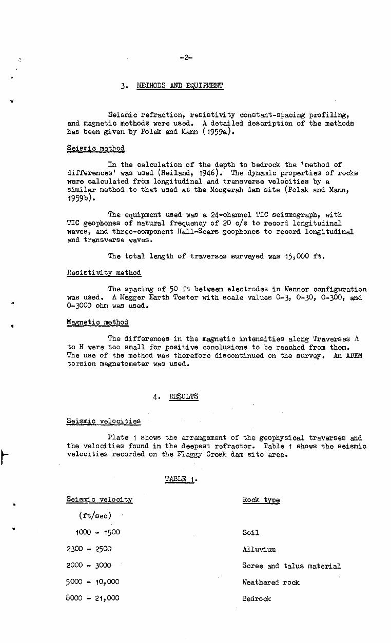
4. RESULTS
Seismic velocities
Plate 1 shows the arrangement of the geopbysical traverses and the velocities found in the deepest refractor. Table 1 shows the seismic velooities reoorded on the Flaggy Creek dam site 'area.
Seismic velocity
(ft/sec)
1000 - 1500
2300 - 2500
2000 - 3000
5000 - 10,000
8000 - 21,000
TABLE 1.
Rock tYpe
Soil
Alluvium
Soree and talus material
Weathered rock
Bedrock

-3-
The very wide range of velocities found in the bedrock m<.\Y' indicate that
( a)
( c)
the rocks at the lower limit of the range are jointed, possibly sheared, and weathered on jOints. Between stations 23 and 27 on Traverse A, near DDH 7, the iow velocity of 8000 ft/sec suggests the ],.lresence of sheared or fractured bedrock,
the rocks with the higher range of velocities are probably solid; if these rocks are jointed, the high velocity would indicate that joints are closed, either by high lateral pressure or recementing,
the seismic velocity in the meta-greYvTacke is higher than in slates; therefore cross-sections with low content of slate show higher velocities,
Plate 1 indicates the velocity anisotropy, ~E.. the velocity along Traverse A (western portion) is lower than that along Traverse J.
Depth determination
The depth to the highest-velocity refractor waS calculate"'. using apparent velocity values that were determined from normal spreads and weathering spreads (Polak and Mann, 1959a). The calculated depths are shown on Plates 2 to 6 with the seismic cross-sections.
Nine diamond-drill holes and two shafts were put down on the site close to the geophysical traverses. These can be used to compare the depth to bedrock obtained by drilling with the depth calculated from the seismic data. The comparison show"a in f}:'able 2, and plot"Ged ~n a graph on Plate 6, indicates that the bedrock depths from seismic~ determ:i .. nations average about 20 percent greater than those f~ul1d by drilling.
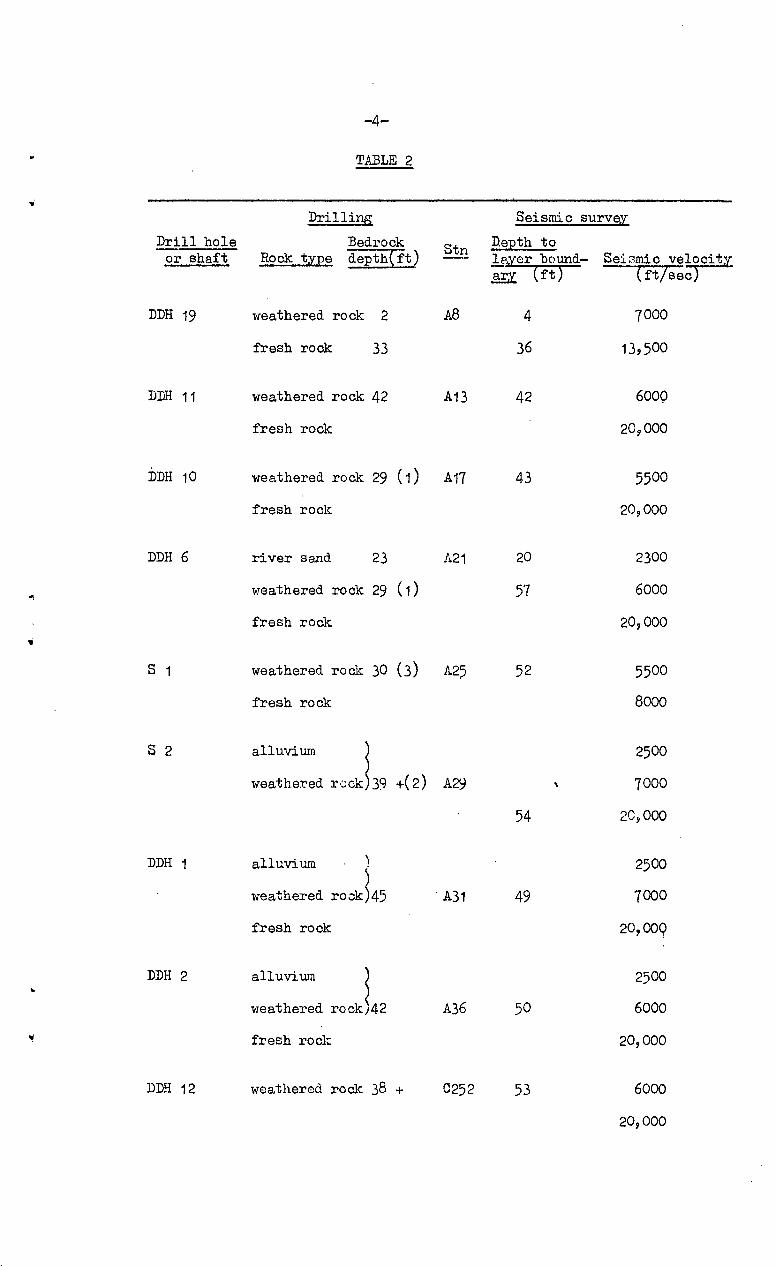
-4-
TABLE 2
,i
Drilli~ Seismic survey
Drill hole Bedrock Stn DeEth to or shaft Rock tJ!:Ee depth{ft) h,J!:sr bound- Sei3mic vel)CitJ!:
arJ!: (ft) -(ft/sec
DDH 19 weathered rock 2 A8 4 7000
fresh rock 33 36 13,500
DDH 11 weathered rock 42 An 42 6000
fresh rock 20,000
DDH 10 weathered rock 29 (1) A17 43 5500
fresh roclc 20,000
DDH 6 river sand 23 11.21 20 2300
weathered rock 29 (1) 57 6000 ..,
fresh rock 20,000
• S 1 weathered rock 30 (3) A25 52 5500
fresh rock 8000
S 2 alluvium l 2500
weathe:red r,~ck 39 +(2) A29 7000
54 2C~000
DDH 1 alluvium l 2500
weathered rO,:}k~45 A31 49 7000
fresh rock 20,009
DDH 2 alluvium l 2500 .. weathered rock 42 A36 50 6000
fresh rock 20,000
DDH 12 weathered rock 38 + 0252 53 6000
20,000

..
..
-5-
D:i.~:i.11ing Seismic survey
Drill hole Bedrock DeEth to Stn or shaft Rock t;y:ee deEth~ft) .l§,yer bo'H1:£.- Seismic velocity ary (ft) (f't/sec)
DDH 13 weathered rock. 49 D268 41 6000 ,
fresh rock 17 ,000
DDH 15 weathered rock. 63 E302 62 6000
fresh rock. 18~00Q
Note: Layer of soil (seismic velocity 1000 - 1500 ft/sec) has been omitted from the table.
Remarks on Tabl e 2:
(a) Possibly a slightly weathered to moderately weathered rock lvaS encountered at a depth of 29 ft in drilling. Such a thin layer could easily be missed in refraction seismic work.
(b) Shaft S2 went only 3 ft in umleathered slate. Weathering may still be present below 39 ft.
(c) No log was 8.vaila.ble for DDH 7; therefore~ shaft S1 was compared with seismic results at A25, although DDH'1 is nearer than S1.
PXnAffii£ Eroperties of rocks
Table 3 gives the results of the tests made at the Flaggy Cre\~k dam site to deternDne tha dynamic properties of the rock presun-(j. The illeas-.J.rements vlere maJ.e using three-compone.nt geophones placed 200 ft apart. Specific gravity of 2.7 i,as assumed for the calculation.
Traverse Station
A 15 - 19
D 274 -278
T.A:3LE 3
Seismic velocit~
Cft/seci
20,000
17 ,000
~sonls
ratio
0.33
0.35
Modulus
Young's
9.7
6.5
6 x 10 IbLsg. in.
Bulk Rigidity
9.3 3.8
7.3 2·5
Poisson's ratio calculated at Flaggy Cl'3ek is hit?her than that obtained at the Barron Falls survey (Polak and Mann, 1959a); it may be indicative of the jointed character of the rock.
.. ,
-6-
Resistivity results.
The variations in apparent resistivity show no correlation with either depth of bedrock or quality of bedrock as indicated by seismic velocities. Hence, they probably reflect near-surface variations in porosity and moisture content and are not significant for the results of the survey. To complete the presentation of the data, they are plotted on Plates 2 to 4 above the seismic profiles.
5. CONCLtruIONS
The overburden at the proposed darn site consists of a thin lqyer of scree material overlying about 50 ft of weathered rock near the creek and about 80 ft farther east. The seismic velocity in the bedrock ranges from 8000 to 21,000 ft/sec. '
BROOKS, J .K.
HEILAND, C.A.
POIIAK~ Eo J. and M.P..NN~ P.E.
PO!_,.ilK, E. J. a~ld
M.P.:NN, FoE.
6. REF'EIRENCES
1957
1946
1959a
1959b
Geological survey Lower Barron River and Flaggy Creek Areas. Geological Survey of Queensla~d (unpubl.)
GIIDPHYSICAL EXPLORl'l.'.i'ION. New York, Prentice-Hall Inc.
Geophysical survey at the Barx'ol1 Falls Hydro-Electric Sc}heme, Kuranda Qld. Bur. Mino Resour. ~ust. Rec. 1959793 (un~ubl.).
A seismic refrHction survey at t:ha M00gera.ll Darn Sj, te near Kal bar, Q",eensland. Bur. Min. Res~ur. ~ust. Ree. 1959762. T~~pub1.-r

o " o o •
. '.
CAIRNS
o
" o
~
17°00' L _____ -'
REFERENCE TO AUSTRALIA STANDARD MAP SERIES
, ' r---'-~-' ,
~---- .. ,.
Oak F., .. ,
I
* !
r ' >
'. , • • • • • J . . . " ' . .'
I •••••••
. ' . , " ..... __ .... _/"
Myo'"
LOCALITY
MILES
, 0 , ....
DOUBLE ISLAND '47
-0 fjlDOHZO
!- (j3~OOI- -
DOH 19
'67
MAP
I , ,
DoHl1
• OOHI4
TRAVERSE A (20,000) ____ .. __ ..
DOHIO
• DDH9 • DOHB
DOH6
.. DOH!!
-- (8000)
, DOH7 I
I f f
FI02
DOH I
\ \ \
' ..... Sha11 52 Shall S I I '
~ f ~ \ \ \ \ \ \
k f I I f f I
, -I
+ F 114
" g o •
/
" g o •
/ 00 o
~\'o'
/
4000 Ft
• DOH 16
• DOH 13
/1
---~ o o o
• DOH III
LeGEND
Onl~ length of fraverses shot ore shown
120.000) Seismic velocit~ In fI /sec
"OOHI
~
Seismic tl'Qverse
Oiomond - drill hole J
Shaft
Co'ordinates: Local Grid
FLAGGY CREEK GEOPHYSICAL SURVEY 1962
SEISMIC TRAVERSE PLAN
FEET
';o;o ..... ,o.o .. "".o .. __________ ~'.o~o ............ ~o.o __________ ... oo Mil __ ; 1
PLATE


a ~ < • ~ • m 8 • o 2 o • m • , " f >: , • r ~ i 1 , ~ , ~ - \ : - ~ o o ~ § , ~ ~ ~ ~.
rTl '" '" "- !II '" 1 VI
or
g " o , o o , ~ ;ii , o o
'"
CD
-c
~ ~
~ ~
o 0
, ,
'"
0 e
0 . "
~ '"
e c
o ~
3 "
o o • o o g N o o " o o
o o en
o , o o o ....
~ '" '" -< 1>
Z o ::0
fTI en
en
-l <
-l -<
"'U
::0
o "'TI r fTI en
, , " "
" S)
"
or
" " N
" ~
C
::!
0 .."
:I
_
C
a i:
~
3 "3
<Il
'"
0 0
9. <'I
l ::
! ~
;-g
c.
g ,
0 ~
:t ::::
I ~
:£
~
-~
c ~
~ ~
;-on
o
~
<II
o " 3
~ g- o , o c ~ en
fT
I en :s:
()
()
::0
o en
en , en
fTI
()
-l o Z en
N
0 < • c o .. N o o o o " " • o -< " l> <
m " I/) m
Ul
(") o l>
2 o m
I~ ,2
o
o m
~
I b CD
m
o " a n '" 5
/
53
58
58
53
48
48
53
62
48
46
48
48
46
40
44
o m
-u
-<
I -<
a CD
[j
;u
a () '"
40
42
55
42
40
40
40
38
40
4/
47
47
46
36
42
38
40
40
45
45
32
47
o '" -u -;
I d CD '" o ;u
a () '" 34
45
42
5/
48
59
55
62
62
5/
53
55
46
46
48
45
38
40
47
56
60
E
o 2 m
r m ~ (5
2 1
35
2
Ul S o Z
2 c '<:
CD
m "
22
4
13
56
12
25
13
43
I 2
21
13
35
I
14
2
1331
1
22
9
13
28
1
23
0
13
28
12
52
13
27
12
32
13
32
13
36
/33
/ 1
23
5
13
26
13
22
/32
1
1318
\2
39
I/) E
o 2 m
r m ; ~
13
23
1321
/3/7
/31
4
13
14
13
/2
13
13
13
15
1315
13
14
13
/4
13
/8
/32
5
13
29
13
29
13
24
13
20
13
20
1321
13
28
13
33
13
32
(f) E
o 2 2 c '<:
CD '" "
26
5
23
8
26
7
27
0
27
5
28
0
28
5
/33
/ I
28
7
Ul ;;j
:j a 2 '" r '" ~ -< o 2
13
29
/33
2
~ a 2 2 C '<:
CD '" ;u
29
4
29
5
13
33
12
96
13
32
12
86
13
31
1
29
8
13
29
/32
91
30
0
/32
7
13
26
13
24
13
25
/32
61
3
05
13
27
13
27
13
25
13
23
13
23
1 3
10
13
26
13
35
13
46
13
54
N '" o " c c 3 N
W
o
~
,," 2 " ~ E
LE
VA
TIO
N
IN
FE
ET
w
o o I i i f ~ '" ~J
, I ,
j;
o o --'
:Ii; m
I/)
-<
~/PTravB
'" g '2
+, I
DO
H 1
2
"
" '"
/P
Tra
, R
" "
" "
" '2
~
,~ \ g '\
'2 I I
i I
+,
I I
" , i I " ' ff
lP
Tro
v 0
fTI
1"'
,>
1>
2 J
g ~
.......
I ~
w
o o
EL
EV
AT
ION
IN
F
EE
T
'" o o
" o o .. o o
:Ii; m
Ul
I / ~
IPT
ravC
-i
i \
" " ~ i
, I '>'
I",
1
< " I
~ 0;-
I
, §' I \ r i ,
DD
H 1
3
I \
r---I P
T
rav
S
~
, ," " " " ~
\ I I I I , \
i \ 1 ' I
I;;;
I I
/P T
ra,
E m
'''I
I--
1>
C)
I U
l
" -<
~ '" o o
EL
EV
AT
ION
IN
F
EE
T
I w
o o ~
"I
C) 2'
~I I I I I
.. o o :;; o o :Ii; m
(f) -<
1 !~ , '" \ ~ l~/P T
mv
D
R;'-
--
'" -''' 2 '"
, ~ I I I I
• I
J :
I ' ~lm: DOH
"
\ ~
~
'" '
" "
" "
" "
I ~ ~
" ," " " '2
I \ , I i r i \ , I
I \ , I , I
w
o o
:ti l::I. ~ I~ ,."
C) :ti l::I. ~ ~ I'lj
t:l
:ti l::I. n; @
I'lj
,."
o o o o o o
AP
PA
RE
NT
R
ES
IST
IVIT
Y
IN OHM~
ME
TR
ES
o o N
o o
"
w
o o .. o o
'" o " '" o o
~
o o '" o o
'" o o
"""'"
........
........
........
........
.
,---
\ \ \ \
--'-
"
-----
'--"
---- '
-', ,
........
". / / / , -' , , ,
---_.
--
o o N
o o '" g
, " o o
---,--- , , '" o o
, , , , '" o o
'\ , , .... o o
'" o o
AP
PA
RE
NT
R
ES
IST
IVIT
Y
IN
OH
M-M
ET
RE
S
o o ... I , I I ,~ I I I I "
N o o
'" o o -- -- -- , , , " / / I \ \ \ \ ,
\ \ \ , ,,'
//
"/"
,,,
.. o o --" o o ---
'" o o .... o o
<
o o
... , "
N o o
" \ \ • '-
"-"':=
:~>
, " ,/
, " ....
........
........
..
, -- - """'"
--,--" -'
..........
. -
..........
,
'" o o
..........
........
" o o
, , , ,
'-,
,/
, / , , , , ,
--),
-' '" o o '" o o
.... o o
'" o o '" o o
AP
PA
RE
NT
R
ES
IST
IVIT
Y
IN
OH
M-M
ET
RE
S
o o N
'"
o
0 o
0
.. o o ~ o o
'" o o
//
..... -'
_/
/ i
/ /
\ \ \ , I I I ,
-r • / / , , I I \ \
/'
/
\ • \ , I , , , t
" .....
..........
.........
" " -'
,,"
, , I I I I , \ I \ I i \ \ \ , I I \ 1 ,
.( ..... "
,
\ \ \
///
/ \
o o
\ \ ~\ \
\ ,
N
'"
o 0
o 0
.. o o '" o o
'" o o
~
o o .... o o
'" o o
o o o o o o
" r !i rTl
VI
• i ~ ~ ~ , ~ r ~ , • • ~ I
" ~
~ {
n o •
! ~
z •
<
~ · ~
g ~.
• o ~ m
•
01
~
01
,
.... "
m
01
I 01
I Q
N
o ~
o o , o < • - n o
o o • o o g " g • g
~
~
~
-I
o (J
)
",
'-' ~
~
::!
~
I 0
-....
z
0 o
z ",
~
~
~
ELE
VA
TIO
N
IN
FE
ET
OJ3
,$
:
~ -
-::O~CD
N
~
.A
O-o
l'T
l
0 0
0 ~
~
0 0
0 A
Z
30
1
39
0
73
•
38
1
39
6
85
I
i_
/
-,.
--
I P r
rov
J
38
/3
89
7
5
,
46
1
38
1
d, I
~
" is
46
1
38
5
T
. 4
8
13
80
I
J 4
8
1374
I
I , 4
8
13
64
8
0
I , 5
0
13
60
/
52
1
35
0
I 4
8
1341
I
42
1
33
/ _ ~
I 4
2
/32
3
85
1
;; I
42
13
15
~I\) ~
/' 4
6
13
03
I.
48
/2
89
_~
/ 4
4
/21
4
f 4
6
/21
1
90
1
50
/2
80
I
'" \
.'<
40
12
83
~
~
o o 1ii
",
~
32
1
28
5
\
26
1
28
1
'\ _~ P Ti-a
, M
--
~ 2
2
12
89
9
5
\ ~
~ ~
I d tIl '" o ;0 is '"
I 51
48
46
40
38
40
42
.-1",,
,, 48
44
48
48
40
46
48
46
5/
53
5/
46
5/
50
(J)
(J)
~ ~
....
....
o 0
z z
'" r '" ~ .... (5
z 12
81
12
82
z c ;::
tIl
,."
;0
19
8
1284
1 2
00
/28
2
/27
8
12
75
/28
1
....J
.Oi'B
Q;".
j."'a
.t)5.
, ..••
.
12
97
13
09
13
00
12
96
1294
1 2
10
(29
4
!29
8
13
05
12
99
12
93
I 2
15
12
85
12
86
12
86
12
88
51
I /2
89
1 2
20
(J)
[Tl
(J) s::
n n ;:0
o (J
) (J
) I (J
) [T
l n -i o Z
(J)
.... :0 !:: '" '" '" rn '" ~ '" r '" "" z o Z
'" o o ~ g
" o o
EL
EV
AT
ION
IN
FE
ET
N o o
I '" .'" is 2
\ I I \ [ \ I I \ I I ,
\ --
+
' I / 1 I
so \
~ 2 N o o
/ \ ,
~
o o
1ii
",
~
.~
:to. ~ Bl rr;
r-
f-IP
Tra
v N
r--IP
T
rav
Q
~/PTravM
w o o
'" J> ~ ~
ro
-0
• •
<
• o
0
o 0
, ,
~
n o
0
;; "
~ '"
-0
o ~
3 • o o '" o o '" o o ~
o , ~ o o ~
, •
o '"
"
'" "
I " "
w
'"
~
c:
;;
2 ~
:::>
-+
C
"'"
'If
<l>
3 3
<l>
"'"
0 C
I C
I en
:::>
--;
. --
;. ~
0.
o· ~:-.
::J
-0
0 ~
::J
::::!.
!.
~ "
~
0 <l>
_
;::r
IJ>
~3.~~.
o ••
n 3
OJ<"
ill
0 ~
o o , o o ~
< " o O. .;;
Q.
p;
o o o s • o
, ~ 8 i
~ :to. ~ ~ i'1i
:>.;
0 ",
1J .... I d tIl '" 0 '" 0 () '"
32
24
26
28
24
28
32
32
32
34
36
38
42
42
40
40
42
40
38
32
46
~
1J .... I d tIl
",
0 '" 0 () " 15 2
0
/9
f1
28
19
25
23
8 1 23
21
25
32
33
40
31
45
45
49
64
63
46
47
40
36
26
26
30
0 '" -U .... I d tIl '" 0 ;0
0 CO '" 42
46
46
46
50
48
54
46
44
38
3B
40
36
(J)
(J)
'-' '-'
::j
.... 0
0 Z
Z
",
r Z
'" c
~
s:
.... tI
l (5
'" '"
Z
13
70
4
1
13
6B
1363
1351
5
0
13
48
13
40
13
40
13
54
13
69
5
5
/38
3
56
13
92
8
13
93
5
8
13
87
13
85
6
0
/38
2
13
75
13
72
13
79
/39
6
65
14
09
14
23
6
1
(J)
(J)
'-' j;!
.... (5
.... (5
z Z
'" r z
'" c
<
;::
!';
tIl
6 '"
z '"
/29
0
/9/
12
86
1
90
12
83
/21
9
12
15
/Z?O
/26
5
/85
12
57
/25
3
12
48
1253
,
/26
6
/BO
/28
2
/29
2
12
90
12
93
13
00
/1
5
13
09
/32
5
13
36
13
44
/1
/
/34
5
/32
1341
/6
9
13
35
13
27
1317
/6
6
/30
8
451
13
09
/3/5
4
53
Cf)
'-' (J
) ~ -i
0 z 0 2
'" r z
'" c
~ s:
.... tI
l (5
'" ;0
z 1
21
4
/02
/28
2
/28
8
12
94
/0
5
12
98
13
03
13
02
/29
5
/2B
B
110
12
82
/21
6
12
13
12
10
/1
4
EL
EV
AT
ION
IN
F
EE
T
0;
" 0
0 0
0
\ , I , / , I / , I , '\
.0,
,
'" \
'" '" ~ , \ \ ~
f4
-I/P
Tr
av A
, I C'
) D
DH
19
2
, I , I , i
\ t-
, I , i
I I
,
I \
, ,
;;,
\ '" '" '" ~
,
Z 0
~
o o
;0 .... I
\ \ IP
rro
v K
~
o o
, .. o o
.~
(J)
0 c .... I -
~
o o
EL
EV
AT
ION
IN
F
EE
T
N
0 0
, , :< '" " " ~ !
-r-- ~ " " ~
-r-- ;;;
.'" '" " ~
N o o
0;
0 0
I '--IP
r'a
, K
I , I , / , \ / , I , \ J I , \ \ , • I , I f+
-IP
Tra
v L
, \ , I , \ \ I
" o o
(J)
0 c .... I
\ ~ \ ~
f..-
IP T
rOl
/ , I , I , , I , ~
o o
Z 0 '" .... I .. o o
B
EL
EV
AT
ION
IN
F
EE
N
0 0 , '" is ~ I I T
, " ~ 1 N
0 0
0; 0 0
\ , ~'U'
-I
"'1"1
f~
• I , \ I~I~
" I '
" jill
il ~ I~
I
j I
, I I I--
/ , I , I
'" 0 0
z § I Trov
P
/PT
rov A
Tro
v L
(J) o c .... I
~ :t.. "" i~ ,v,
'1'tJ ~
, ~ l;;
~ ~ i'1i
1<... ~ l;; ~ ,~
,,~
~
" r ~
IT!
01
ILU LU U.
~
'" 1300 -'" ~ CI.. ....
TRAVERSE P
WEST EAST r 1300
~
Z o
, --_.---------.. ---.--------~.-.-.-.-.-I-:; +-----~~------------~~~-(16,000) ---~~~~~~-
w 1200 --' w
.., STATION NUMBER :j::
STATION ELEVATION I!: "::!
DEPTH TO -BEDROCK C> '<t
TRAVERSE Q
SOUTH
--
t-1200
CI..
'" " NORTH ~ CI.. ....
~~::~~~~~~----~~1300 . -------------.-----
I-
~ 1300 -t----- --(6000l • _____ .- • ______ .---!!.~OO) .--. ....,.,.,,--+----
z - --
"---0 z o t= :; t-~---------~~~-__1/~000)-~~~~~~-L~~~~~~~
'j 1200 -w
STATION NUMBER ~
C> STATION ELEVATION ~ ....
DEPTH TO BEDROCK ~ ~ '<t
TRAVERSE R
1400 NORTH SOUTH -1400
I-:::J 1300 u.
(6000) ---------+�300
z .--.--._--.--'-..... is _.__ .~, ___ .---.,--.-,
~ t--~~-·~~~--(2f,000) j (f6,000)~------; d 1200- 1200
STATION NUMBER ~
STATION ELEVATION :e "::!
DEPTH TO BEDROCK ~
TRAVERSE S
1400 - NORTH
Iw w "z
z o I-
'" >
1300 -
;---.-----.~.----.
SOUTH 1400
1 -----_________________ JrI300
.-----.--.,~--.- '------------,----, w
--' w
t--~~~---------(17,000)---------~~~~~~~
1200 -
STATION NUMBER
STATION ELEVATION ~ "::!
DEPTH TO BEDROCK :g '<>
'" CI) '<t
rl200
TRAVERSE T 1400 NORTH ..
'" ~ CI..
SOUTH rl400
Iw W u. 1300
1 ~----------------------------L-~-------------------------------------+------______ JLI300
~
z o ~
~ ~.--.----.'---.-.'---.~- ~.--.------> LU -' W 1200
.-----.-----.~ ------. I ______ ---;H 200 l------------( 15,000) ---------1t...------ (20,000)
STATION NUMBER ~
STATION ELEVATION ~
DEPTH TO BEDROCK '<>
'"
'" z -' -' i>: o ::E o Q: U.
70 .
60 -
50
40-
30
/ I ICL w o
20 /
10 /
~ o ' 10
/
20
/ . / /. .... .
/ U
/ /
/
/. /
/ • • •
, , 30 40 50 6<) 70
DEPTH FROM SEISMIC RESULTS (FT)
'<> 8
LEGEND
(6000) Formation with seismic velocity of 6000 fVsec
DOH 12 Diamond-drill hole 12
I P Intersection paint
• ___ • Unweathered bedrock bounda',,y
100 I
, Unweathered bedrock not reached
Based on COG Maps 1004,1007, 1009,and 1011
Elevation: State datum
TRAVERSES P, Q,R,S, AND T
SEISMIC CROSS- SECTIONS
FEET
50 o 100 200
(Horizontol and Vertical)
300
PLATE 6
TO ACCOMPANY RECORD No. 1963/111