Embed Size (px)
Citation preview
< S T A N D A R D S >
FK Series Butterfly ValvesProduct Data Sheet
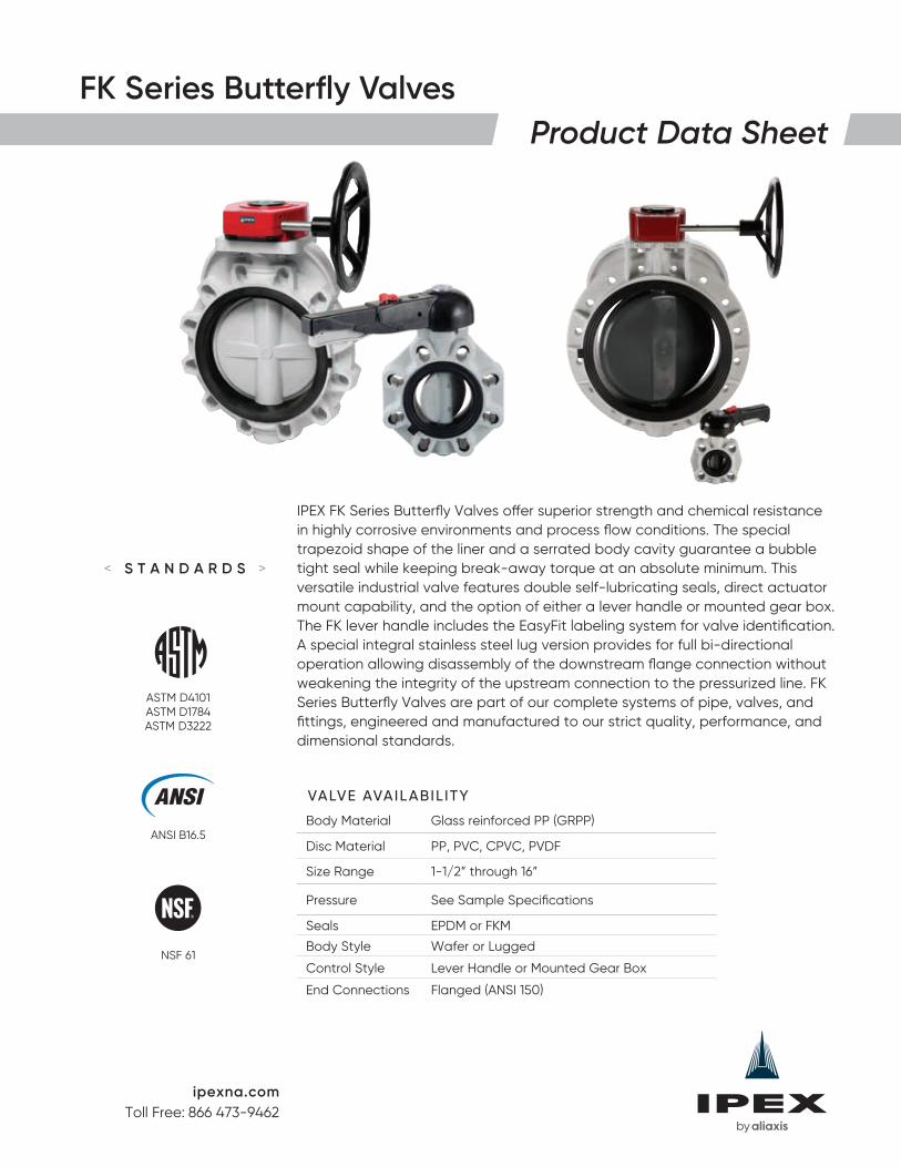
IPEX FK Series Butterfly Valves offer superior strength and chemical resistance in highly corrosive environments and process flow conditions. The special trapezoid shape of the liner and a serrated body cavity guarantee a bubble tight seal while keeping break-away torque at an absolute minimum. This versatile industrial valve features double self-lubricating seals, direct actuator mount capability, and the option of either a lever handle or mounted gear box. The FK lever handle includes the EasyFit labeling system for valve identification. A special integral stainless steel lug version provides for full bi-directional operation allowing disassembly of the downstream flange connection without weakening the integrity of the upstream connection to the pressurized line. FK Series Butterfly Valves are part of our complete systems of pipe, valves, and fittings, engineered and manufactured to our strict quality, performance, and dimensional standards.
VALVE AVAIL ABIL ITY
Body Material Glass reinforced PP (GRPP)
Disc Material PP, PVC, CPVC, PVDF
Size Range 1-1/2” through 16”
Pressure See Sample Specifications
Seals EPDM or FKM
Body Style Wafer or Lugged
Control Style Lever Handle or Mounted Gear Box
End Connections Flanged (ANSI 150)
ANSI B16.5
ASTM D4101ASTM D1784ASTM D3222
NSF 61
ipexna.comToll Free: 866 473-9462
2
FK Series Butterfly ValvesProduct Data Sheet
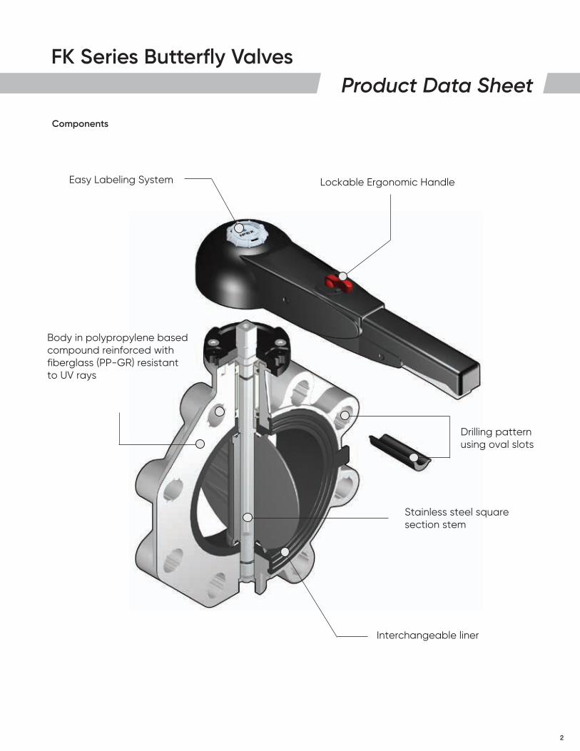
Components
Easy Labeling System
Body in polypropylene based compound reinforced with fiberglass (PP-GR) resistant to UV rays
Lockable Ergonomic Handle
Drilling pattern using oval slots
Stainless steel square section stem
Interchangeable liner
3
FK Series Butterfly ValvesProduct Data Sheet
Sample Specifications
1.0 Butterfly Valves – FK
1.1 Material
• The valve body shall be made of glass reinforced polypropylene (GRPP) obtained from homopolymer polypropylene (PPH).
• The valve disc shall be made of stabilized PP homopolymer compound, also containing a RAL 7032 pigment, which shall meet or exceed the requirements of Type I Polypropylene according to ASTM D4101.
or The valve disc shall be made of PVC compound which shall meet or exceed the requirements of cell classification 12454 according to ASTM D1784.
or The valve disc shall be made of Corzan® CPVC compound which shall meet or exceed the requirements of 23447 according to ASTM D1784.
or The valve disc shall be made of virgin, non-regrind PVDF compound which shall meet or exceed the requirements of Table 1 according to ASTM D3222.
• These compounds shall be listed with NSF to Standard 61 for potable water.
• The valve shaft shall be made of 316 stainless steel.
1.2 Seats
• The disc liner shall be made of EPDM.
or The disc liner shall be made of FKM.
1.3 Seals
• The o-ring seals shall be made of EPDM.
or The o-ring seals shall be made of FKM.
2.0 Connections
2.1 Flanged style
• The ANSI 150 flanged connections shall conform to the dimensional standard ANSI B16.5.
3.0 Design Features
• The valve shall be of either wafer or lugged design (specifier must select one).
• The lugged style shall feature permanently integrated stainless steel lugs.
• Manual control of the valve shall be achieved through the use of either a lever handle or mounted gear box (specifier must select one).
• The shaft shall have standard ISO square dimensions for direct mounting of actuators.
• The disc seat shall be a trapezoidal elastomeric liner and provide a bubble tight seal.
• The liner shall completely isolate the valve body from the process flow.
• The liner shall function as a flange gasket on both sides of the valve.
• The body cavity shall feature special channeling to prevent liner slippage and compression.
• The disc, seats, and seals shall be the only wetted parts.
• Teflon® seated o-ring seals shall prevent the stainless steel shaft from becoming wetted.
• The handle shall incorporate a transparent PVC plug and tag holder for valve identification.
4
FK Series Butterfly ValvesProduct Data Sheet
3.1 Pressure Rating
PP Disc, Wafer Style
• 1-1/2" to 10" shall be rated at 150 psi at 73°F
• 12" shall be rated at 120 psi at 73°F
• 14" shall be rated at 100 psi at 73°F
• 16" shall be rated at 85 psi at 73°F
PVC Disc, Wafer Style
• 14" shall be rated at 100 psi at 73°F
• 16" shall be rated at 85 psi at 73°F
CPVC Disc, Wafer Style
• 1-1/2" and 2" shall be rated at 232 psi at 73°F
• 2-1/2" to 10" shall be rated at 150 psi at 73°F
• 12" shall be rated at 120 psi at 73°F
PVDF Disc, Wafer Style
• 1-1/2" and 2" shall be rated at 232 psi at 73°F
• 2-1/2" to 10" shall be rated at 150 psi at 73°F
• 12" shall be rated at 120 psi at 73°F
PP Disc, Lugged Style
• 2-1/2" to 8" shall be rated at 150 psi at 73°F
• 10" and 12" shall be rated at 85 psi at 73°F
CPVC Disc, Lugged Style
• 2-1/2" to 8" shall be rated at 150 psi at 73°F
• 12" shall be rated at 85 psi at 73°F
PVDF Disc, Lugged Style
• 2-1/2" to 8" shall be rated at 150 psi at 73°F
• 12" shall be rated at 85 psi at 73°F
3.2 Markings
• All valves shall be marked to indicate size, material designation, and manufacturers name or trade mark.
3.3 Color Coding
• All valve bodies shall be color-coded beige gray.
• PP valve discs shall be color-coded beige gray
• PVC valve discs shall be color-coded dark gray
• CPVC valve discs shall be color-coded light gray
• PVDF valve discs shall not be color-coded and be white in appearnce
4.0 All valves shall be listed to NSF Standard 61 for potable water.
5.0 All valves shall be by IPEX or approved equal.
5
FK Series Butterfly ValvesProduct Data Sheet
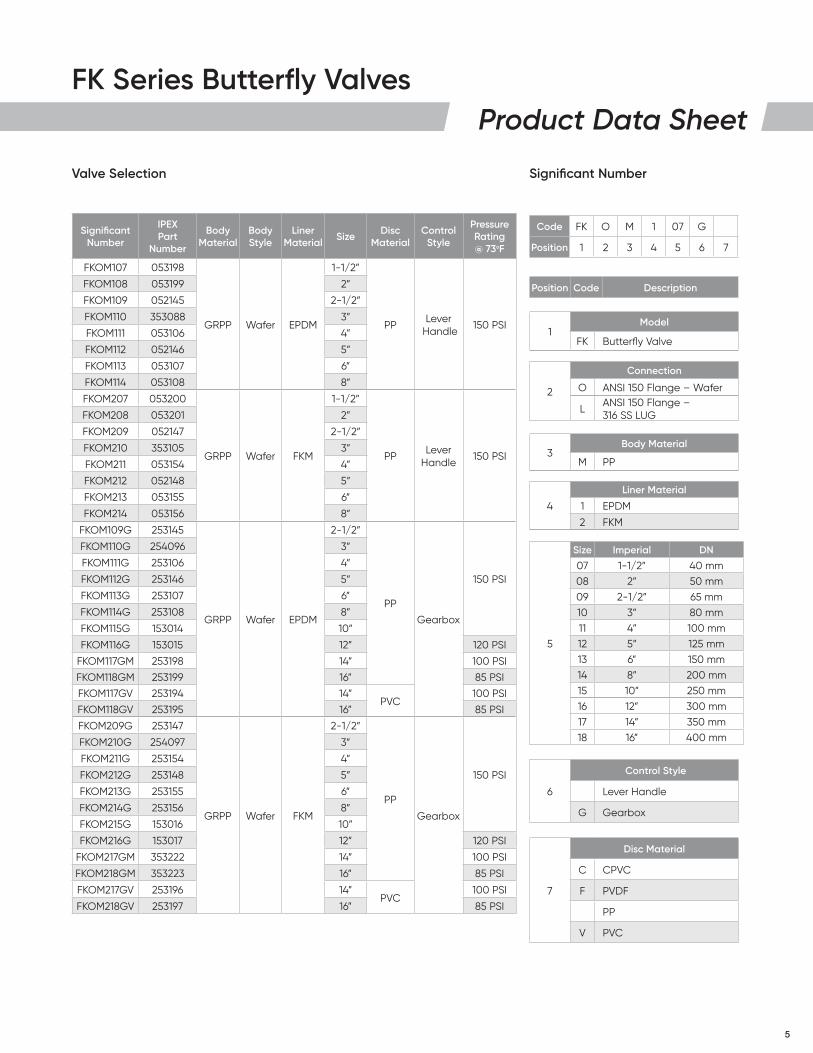
Valve Selection Significant Number
Code FK O M 1 07 G
Position 1 2 3 4 5 6 7
Position Code Description
1Model
FK Butterfly Valve
2
Connection
O ANSI 150 Flange – Wafer
L ANSI 150 Flange – 316 SS LUG
3Body Material
M PP
4
Liner Material
1 EPDM
2 FKM
5
Size Imperial DN
07 1-1/2” 40 mm08 2” 50 mm09 2-1/2” 65 mm10 3” 80 mm11 4” 100 mm12 5” 125 mm13 6” 150 mm14 8” 200 mm15 10” 250 mm16 12” 300 mm17 14” 350 mm18 16” 400 mm
6
Control Style
Lever Handle
G Gearbox
7
Disc Material
C CPVC
F PVDF
PP
V PVC
Significant Number
IPEX Part
Number
Body Material
Body Style
Liner Material Size Disc
MaterialControl
Style
Pressure Rating @ 73oF
FKOM107 053198
GRPP Wafer EPDM
1-1/2”
PP Lever Handle 150 PSI
FKOM108 053199 2”
FKOM109 052145 2-1/2”
FKOM110 353088 3”
FKOM111 053106 4”
FKOM112 052146 5”
FKOM113 053107 6”
FKOM114 053108 8”
FKOM207 053200
GRPP Wafer FKM
1-1/2”
PP Lever Handle 150 PSI
FKOM208 053201 2”
FKOM209 052147 2-1/2”
FKOM210 353105 3”
FKOM211 053154 4”
FKOM212 052148 5”
FKOM213 053155 6”
FKOM214 053156 8”
FKOM109G 253145
GRPP Wafer EPDM
2-1/2”
PP
Gearbox
150 PSI
FKOM110G 254096 3”
FKOM111G 253106 4”
FKOM112G 253146 5”
FKOM113G 253107 6”
FKOM114G 253108 8”
FKOM115G 153014 10”
FKOM116G 153015 12” 120 PSI
FKOM117GM 253198 14” 100 PSI
FKOM118GM 253199 16” 85 PSI
FKOM117GV 253194 14”PVC
100 PSI
FKOM118GV 253195 16” 85 PSI
FKOM209G 253147
GRPP Wafer FKM
2-1/2”
PP
Gearbox
150 PSI
FKOM210G 254097 3”
FKOM211G 253154 4”
FKOM212G 253148 5”
FKOM213G 253155 6”
FKOM214G 253156 8”
FKOM215G 153016 10”
FKOM216G 153017 12” 120 PSI
FKOM217GM 353222 14” 100 PSI
FKOM218GM 353223 16” 85 PSI
FKOM217GV 253196 14”PVC
100 PSI
FKOM218GV 253197 16” 85 PSI
6
FK Series Butterfly ValvesProduct Data Sheet
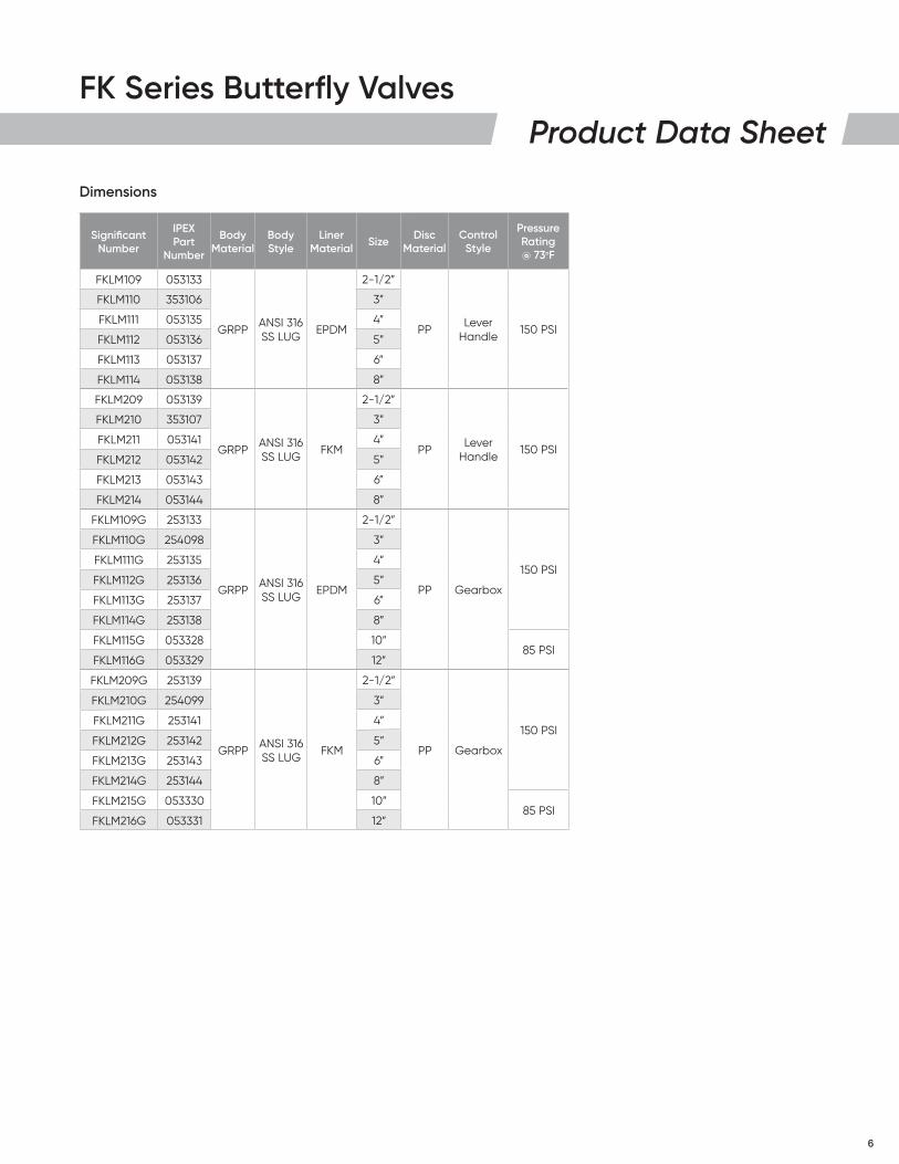
Dimensions
Significant Number
IPEX Part
Number
Body Material
Body Style
Liner Material Size Disc
MaterialControl
Style
Pressure Rating @ 73oF
FKLM109 053133
GRPPANSI 316 SS LUG
EPDM
2-1/2”
PPLever
Handle150 PSI
FKLM110 353106 3”
FKLM111 053135 4”
FKLM112 053136 5”
FKLM113 053137 6”
FKLM114 053138 8”
FKLM209 053139
GRPPANSI 316 SS LUG
FKM
2-1/2”
PPLever
Handle150 PSI
FKLM210 353107 3”
FKLM211 053141 4”
FKLM212 053142 5”
FKLM213 053143 6”
FKLM214 053144 8”
FKLM109G 253133
GRPPANSI 316 SS LUG
EPDM
2-1/2”
PP Gearbox
150 PSI
FKLM110G 254098 3”
FKLM111G 253135 4”
FKLM112G 253136 5”
FKLM113G 253137 6”
FKLM114G 253138 8”
FKLM115G 053328 10”85 PSI
FKLM116G 053329 12”
FKLM209G 253139
GRPPANSI 316 SS LUG
FKM
2-1/2”
PP Gearbox
150 PSI
FKLM210G 254099 3”
FKLM211G 253141 4”
FKLM212G 253142 5”
FKLM213G 253143 6”
FKLM214G 253144 8”
FKLM215G 053330 10”85 PSI
FKLM216G 053331 12”
7
FK Series Butterfly ValvesProduct Data Sheet
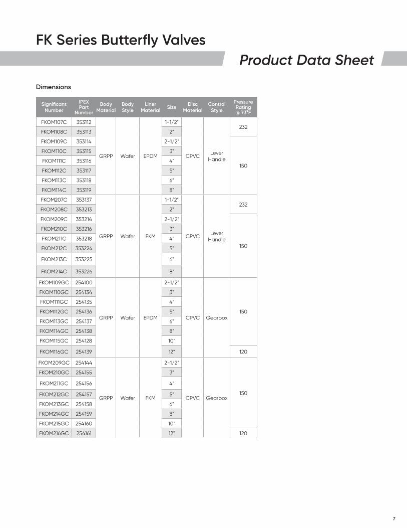
Significant Number
IPEX Part
Number
Body Material
Body Style
Liner Material Size Disc
MaterialControl
Style
Pressure Rating @ 73°F
FKOM107C 353112
GRPP Wafer EPDM
1-1/2"
CPVC Lever Handle
232FKOM108C 353113 2"
FKOM109C 353114 2-1/2"
150
FKOM110C 353115 3"
FKOM111C 353116 4"
FKOM112C 353117 5"
FKOM113C 353118 6"
FKOM114C 353119 8"
FKOM207C 353137
GRPP Wafer FKM
1-1/2"
CPVC Lever Handle
232FKOM208C 353213 2"
FKOM209C 353214 2-1/2"
150
FKOM210C 353216 3"
FKOM211C 353218 4"
FKOM212C 353224 5"
FKOM213C 353225 6"
FKOM214C 353226 8"
FKOM109GC 254100
GRPP Wafer EPDM
2-1/2"
CPVC Gearbox150
FKOM110GC 254134 3"
FKOM111GC 254135 4"
FKOM112GC 254136 5"
FKOM113GC 254137 6"
FKOM114GC 254138 8"
FKOM115GC 254128 10"
FKOM116GC 254139 12" 120
FKOM209GC 254144
GRPP Wafer FKM
2-1/2"
CPVC Gearbox150
FKOM210GC 254155 3"
FKOM211GC 254156 4"
FKOM212GC 254157 5"
FKOM213GC 254158 6"
FKOM214GC 254159 8"
FKOM215GC 254160 10"
FKOM216GC 254161 12" 120
Dimensions

8
FK Series Butterfly ValvesProduct Data Sheet
Significant Number
IPEX Part
Number
Body Material
Body Style
Liner Material Size Disc
MaterialControl
Style
Pressure Rating @ 73°F
FKLM109C 353120
GRPP ANSI 316 SS LUG EPDM
2-1/2"
CPVC Lever Handle 150
FKLM110C 353121 3"
FKLM111C 353122 4"
FKLM112C 353123 5"
FKLM113C 353129 6"
FKLM114C 353130 8"
FKLM209C 353159
GRPP ANSI 316 SS LUG FKM
2-1/2"
CPVC Lever Handle 150
FKLM210C 353167 3"
FKLM211C 353168 4"
FKLM212C 353169 5"
FKLM213C 353170 6"
FKLM214C 353171 8"
FKLM109GC 254171
GRPP ANSI 316 SS LUG EPDM
2-1/2"
CPVC Gearbox
150
FKLM110GC 254172 3"
FKLM111GC 254173 4"
FKLM112GC 254174 5"
FKLM113GC 254175 6"
FKLM114GC 254176 8"
FKLM115GC 254142 10"85
FKLM116GC 254143 12"
FKLM209GC 254165
GRPP ANSI 316 SS LUG FKM
2-1/2"
CPVC Gearbox
150
FKLM210GC 254166 3"
FKLM211GC 254167 4"
FKLM212GC 254168 5"
FKLM213GC 254169 6"
FKLM214GC 254170 8"
FKLM215GC 254119 10"85
FKLM216GC 254164 12"
Dimensions
9
FK Series Butterfly ValvesProduct Data Sheet
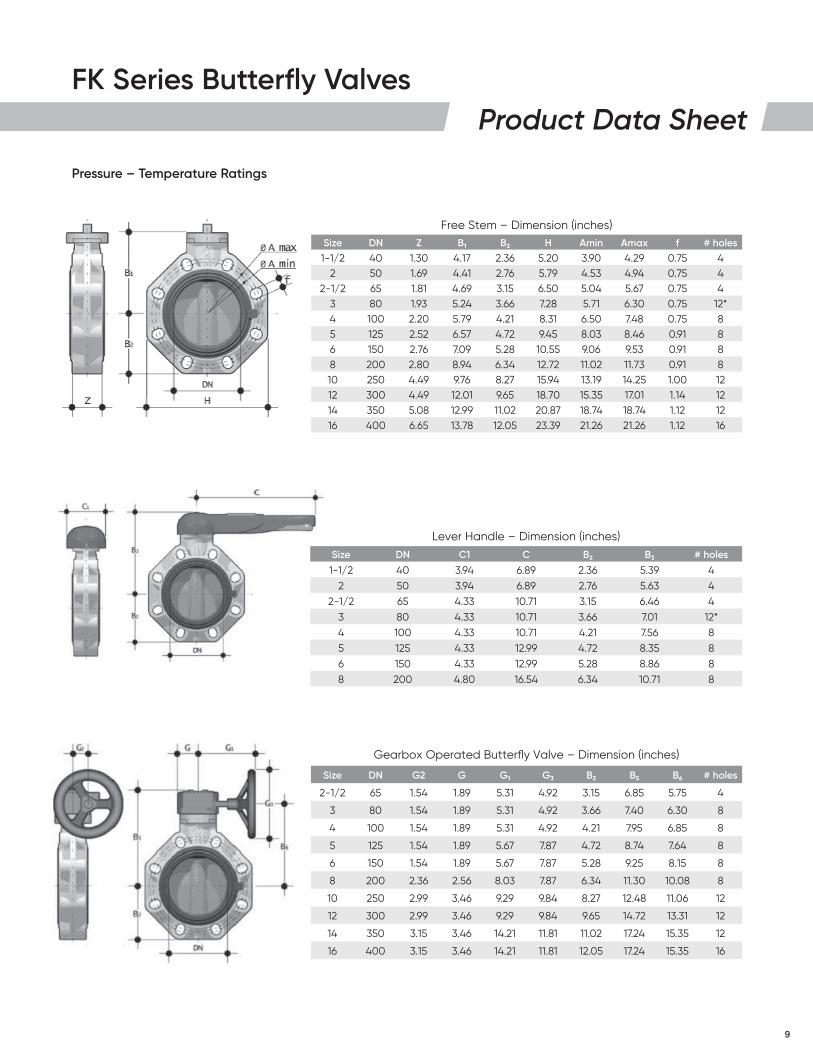
Pressure – Temperature Ratings
Free Stem – Dimension (inches)Size DN Z B1 B2 H Amin Amax f # holes1-1/2 40 1.30 4.17 2.36 5.20 3.90 4.29 0.75 4
2 50 1.69 4.41 2.76 5.79 4.53 4.94 0.75 42-1/2 65 1.81 4.69 3.15 6.50 5.04 5.67 0.75 4
3 80 1.93 5.24 3.66 7.28 5.71 6.30 0.75 12*4 100 2.20 5.79 4.21 8.31 6.50 7.48 0.75 85 125 2.52 6.57 4.72 9.45 8.03 8.46 0.91 86 150 2.76 7.09 5.28 10.55 9.06 9.53 0.91 88 200 2.80 8.94 6.34 12.72 11.02 11.73 0.91 810 250 4.49 9.76 8.27 15.94 13.19 14.25 1.00 1212 300 4.49 12.01 9.65 18.70 15.35 17.01 1.14 1214 350 5.08 12.99 11.02 20.87 18.74 18.74 1.12 1216 400 6.65 13.78 12.05 23.39 21.26 21.26 1.12 16
Lever Handle – Dimension (inches)Size DN C1 C B2 B3 # holes
1-1/2 40 3.94 6.89 2.36 5.39 42 50 3.94 6.89 2.76 5.63 4
2-1/2 65 4.33 10.71 3.15 6.46 43 80 4.33 10.71 3.66 7.01 12*4 100 4.33 10.71 4.21 7.56 85 125 4.33 12.99 4.72 8.35 86 150 4.33 12.99 5.28 8.86 88 200 4.80 16.54 6.34 10.71 8
Gearbox Operated Butterfly Valve – Dimension (inches)
Size DN G2 G G1 G3 B2 B5 B6 # holes
2-1/2 65 1.54 1.89 5.31 4.92 3.15 6.85 5.75 4
3 80 1.54 1.89 5.31 4.92 3.66 7.40 6.30 8
4 100 1.54 1.89 5.31 4.92 4.21 7.95 6.85 8
5 125 1.54 1.89 5.67 7.87 4.72 8.74 7.64 8
6 150 1.54 1.89 5.67 7.87 5.28 9.25 8.15 8
8 200 2.36 2.56 8.03 7.87 6.34 11.30 10.08 8
10 250 2.99 3.46 9.29 9.84 8.27 12.48 11.06 12
12 300 2.99 3.46 9.29 9.84 9.65 14.72 13.31 12
14 350 3.15 3.46 14.21 11.81 11.02 17.24 15.35 12
16 400 3.15 3.46 14.21 11.81 12.05 17.24 15.35 16
10
FK Series Butterfly ValvesProduct Data Sheet
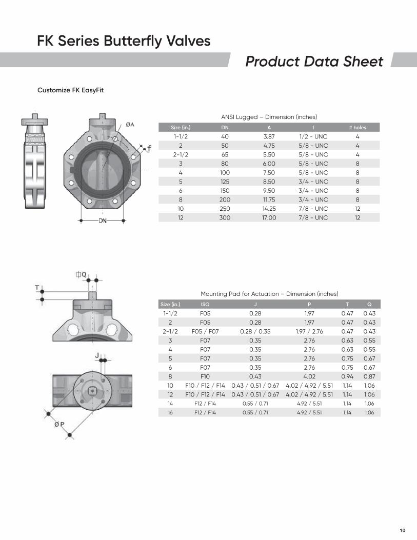
ANSI Lugged – Dimension (inches)
Size (in.) DN A f # holes
1-1/2 40 3.87 1/2 - UNC 42 50 4.75 5/8 - UNC 4
2-1/2 65 5.50 5/8 - UNC 43 80 6.00 5/8 - UNC 84 100 7.50 5/8 - UNC 85 125 8.50 3/4 - UNC 86 150 9.50 3/4 - UNC 88 200 11.75 3/4 - UNC 810 250 14.25 7/8 - UNC 1212 300 17.00 7/8 - UNC 12
Mounting Pad for Actuation – Dimension (inches)
Size (in.) ISO J P T Q
1-1/2 F05 0.28 1.97 0.47 0.432 F05 0.28 1.97 0.47 0.43
2-1/2 F05 / F07 0.28 / 0.35 1.97 / 2.76 0.47 0.433 F07 0.35 2.76 0.63 0.554 F07 0.35 2.76 0.63 0.555 F07 0.35 2.76 0.75 0.676 F07 0.35 2.76 0.75 0.678 F10 0.43 4.02 0.94 0.8710 F10 / F12 / F14 0.43 / 0.51 / 0.67 4.02 / 4.92 / 5.51 1.14 1.0612 F10 / F12 / F14 0.43 / 0.51 / 0.67 4.02 / 4.92 / 5.51 1.14 1.0614 F12 / F14 0.55 / 0.71 4.92 / 5.51 1.14 1.06
16 F12 / F14 0.55 / 0.71 4.92 / 5.51 1.14 1.06
Customize FK EasyFit
11
FK Series Butterfly ValvesProduct Data Sheet
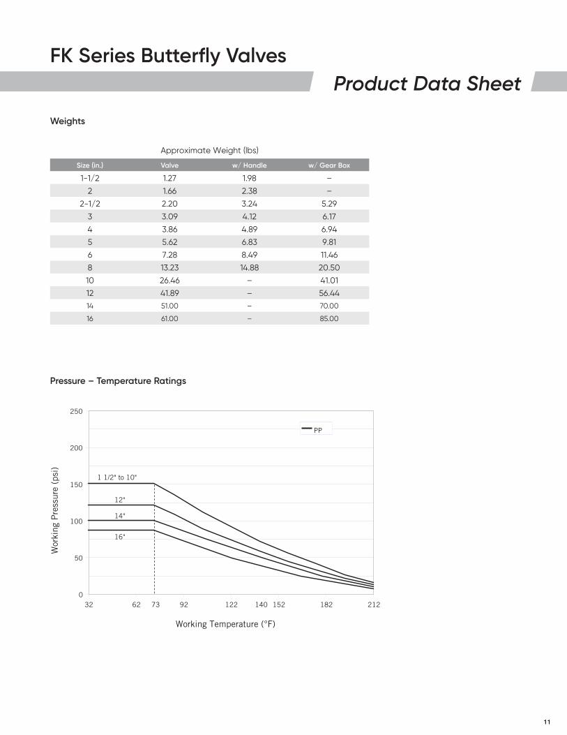
Pressure – Temperature Ratings
Weights
0
50
100
150
200
250
32 62 92 122 152 182 212
Working Temperature (°F)
Wor
king
Pre
ssur
e (p
si)
73 140
PP
1 1/2" to 10"
12"
14"
16"
Approximate Weight (lbs)
Size (in.) Valve w/ Handle w/ Gear Box
1-1/2 1.27 1.98 –
2 1.66 2.38 –
2-1/2 2.20 3.24 5.29
3 3.09 4.12 6.17
4 3.86 4.89 6.94
5 5.62 6.83 9.81
6 7.28 8.49 11.46
8 13.23 14.88 20.50
10 26.46 – 41.01
12 41.89 – 56.4414 51.00 – 70.00
16 61.00 – 85.00
12
FK Series Butterfly ValvesProduct Data Sheet
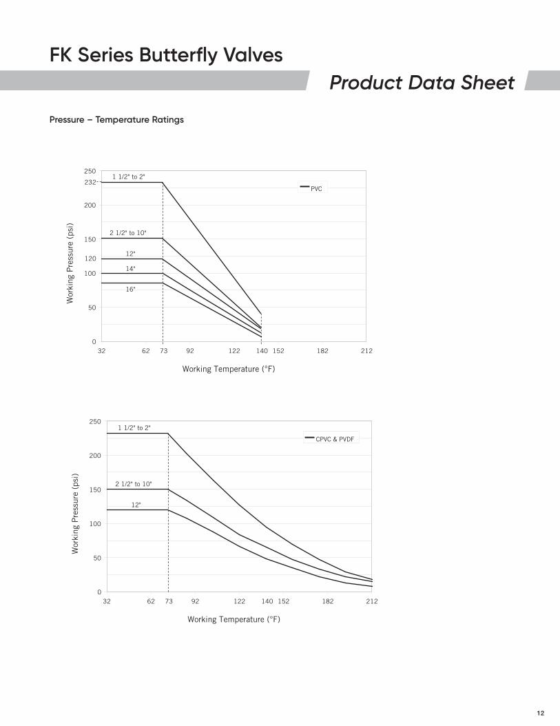
Pressure – Temperature Ratings
0
50
100
150
200
250
32 62 92 122 152 182 212
Working Temperature (°F)
Wor
king
Pre
ssur
e (p
si)
73 140
PVC
2 1/2" to 10"
12"
14"
16"
120
1 1/2" to 2"232
0
50
100
150
200
250
32 62 92 122 152 182 212
Working Temperature (°F)
Wor
king
Pre
ssur
e (p
si)
73 140
CPVC & PVDF
2 1/2" to 10"
12"
1 1/2" to 2"
13
FK Series Butterfly ValvesProduct Data Sheet
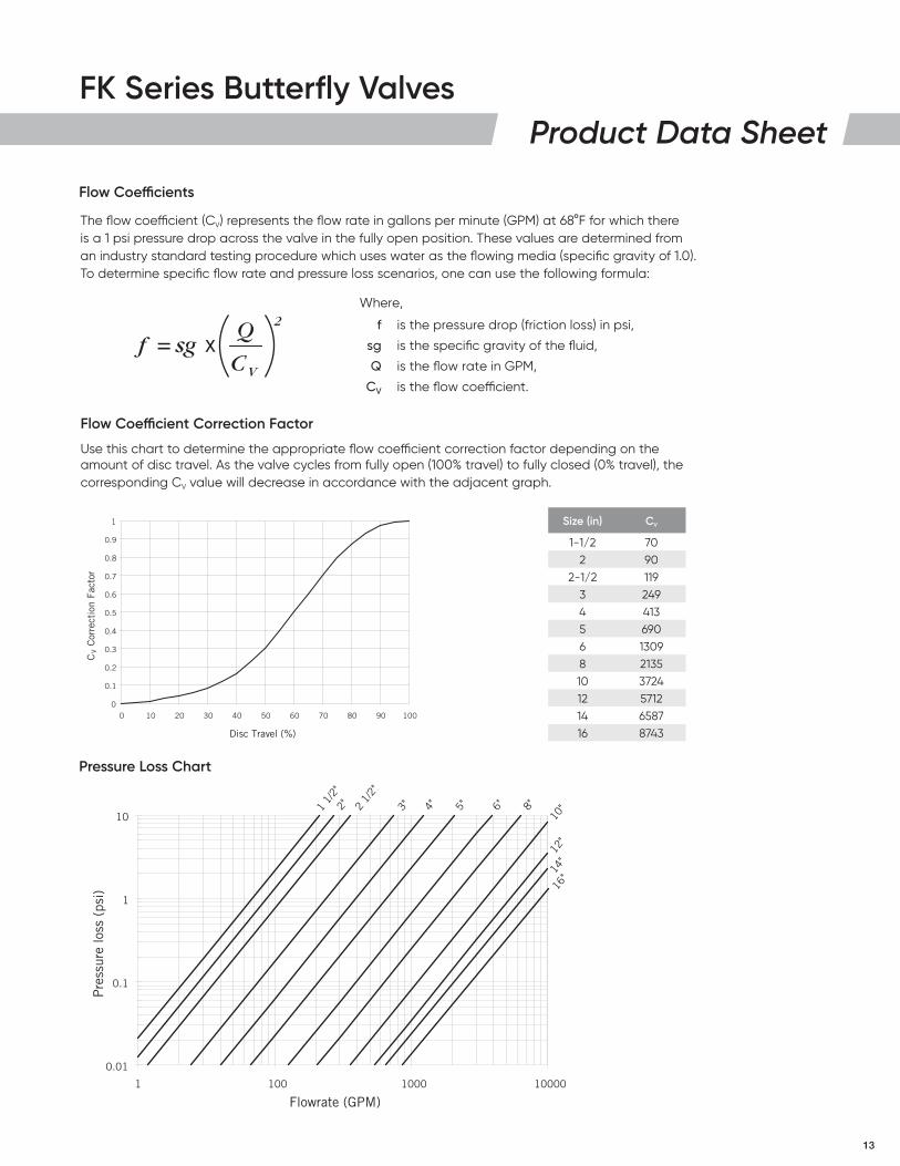
The flow coefficient (CV) represents the flow rate in gallons per minute (GPM) at 68°F for which there is a 1 psi pressure drop across the valve in the fully open position. These values are determined from an industry standard testing procedure which uses water as the flowing media (specific gravity of 1.0). To determine specific flow rate and pressure loss scenarios, one can use the following formula:
Flow Coefficient Correction Factor
Use this chart to determine the appropriate flow coefficient correction factor depending on the amount of disc travel. As the valve cycles from fully open (100% travel) to fully closed (0% travel), the corresponding CV value will decrease in accordance with the adjacent graph.
Flow Coefficients
0.01
0.1
1
10
1 100 1000 10000
Pre
ssur
e lo
ss (
psi)
Flowrate (GPM)
1 1/
2"2" 2
1/2"
3" 4" 5" 6" 8"
10"
12"
14"
16"
0
0.1
0.2
0.3
0.4
0.5
0.6
0.7
0.8
0.9
1
0 10 20 30 40 50 60 70 80 90 100
Disc Travel (%)
CV C
orre
ctio
n Fa
ctor
Pressure Loss Chart
Where,
f is the pressure drop (friction loss) in psi,
sg is the specific gravity of the fluid,
Q is the flow rate in GPM,
CV is the flow coefficient.
2
VC
Qx= sgf
Size (in) CV
1-1/2 702 90
2-1/2 1193 2494 4135 6906 13098 213510 372412 571214 658716 8743
14
FK Series Butterfly ValvesProduct Data Sheet
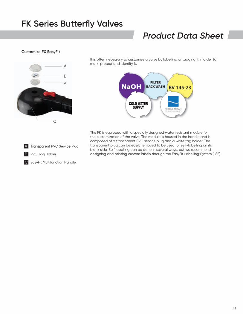
It is often necessary to customize a valve by labelling or tagging it in order to mark, protect and identify it.
The FK is equipped with a specially designed water resistant module for the customization of the valve. The module is housed in the handle and is composed of a transparent PVC service plug and a white tag holder. The transparent plug can be easily removed to be used for self-labelling on its blank side. Self labelling can be done in several ways, but we recommend designing and printing custom labels through the EasyFit Labelling System (LSE).
Customize FX EasyFit
A Transparent PVC Service Plug
B PVC Tag Holder
C EasyFit Multifunction Handle
A
B
A
C
15
FK Series Butterfly ValvesProduct Data Sheet
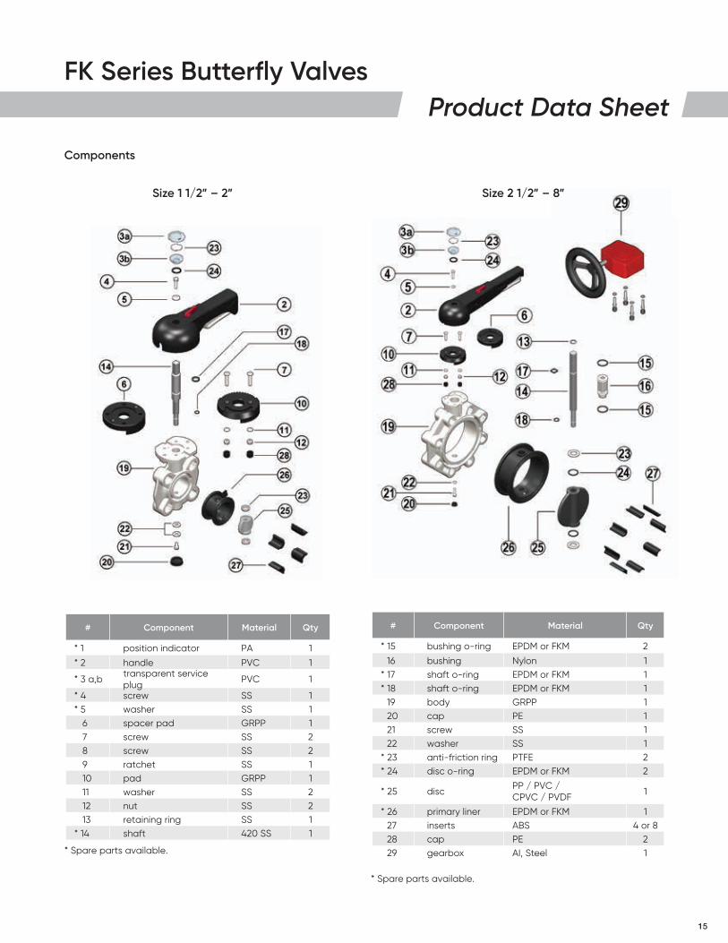
Components
Size 1 1/2” – 2”
# Component Material Qty
* 1 position indicator PA 1
* 2 handle PVC 1
* 3 a,b transparent service plug
PVC 1
* 4 screw SS 1* 5 washer SS 1
6 spacer pad GRPP 17 screw SS 28 screw SS 29 ratchet SS 110 pad GRPP 111 washer SS 212 nut SS 213 retaining ring SS 1
* 14 shaft 420 SS 1
# Component Material Qty
* 15 bushing o-ring EPDM or FKM 2
16 bushing Nylon 1* 17 shaft o-ring EPDM or FKM 1* 18 shaft o-ring EPDM or FKM 1
19 body GRPP 120 cap PE 121 screw SS 122 washer SS 1
* 23 anti-friction ring PTFE 2* 24 disc o-ring EPDM or FKM 2
* 25 discPP / PVC / CPVC / PVDF
1
* 26 primary liner EPDM or FKM 127 inserts ABS 4 or 828 cap PE 229 gearbox AI, Steel 1
Size 2 1/2” – 8”
* Spare parts available.
* Spare parts available.
16
FK Series Butterfly ValvesProduct Data Sheet
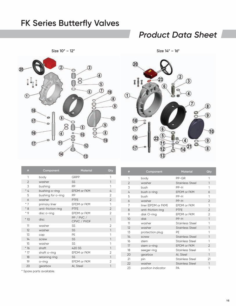
Size 10” – 12” Size 14” – 16”
# Component Material Qty
1 body PP-GR 1
2 washer Stainless Steel 13 bush PP-H 14 bush o-ring EPDM or FKM 65 bush PP-H 16 washer PP-H 27 liner (EPDM or FKM) EPDM or FKM 18 anti-friction ring PTFE 29 disk O-ring EPDM or FKM 210 disk PP-H 111 washer Stainless Steel 112 washer Stainless Steel 113 protection plug PE 114 screw Stainless Steel 116 stem Stainless Steel 117 stem o-ring EPDM or FKM 218 seeger ring Stainless Steel 120 gearbox AI, Steel 121 pin Stainless Steel 2122 washer Stainless Steel 123 position indicator PA 1
# Component Material Qty
1 body GRPP 1
2 washer SS 13 bushing PP 1
* 4 bushing o-ring EPDM or FKM 45 bushing for o-ring PP 26 washer PTFE 2
* 7 primary liner EPDM or FKM 1* 8 anti-friction ring PTFE 2* 9 disc o-ring EPDM or FKM 2
* 10 disc PP / PVC / CPVC / PVDF
1
11 washer SS 212 washer SS 113 cap PE 114 screw SS 115 washer SS 1
* 16 shaft 420 SS 1* 17 shaft o-ring EPDM or FKM 2
18 retaining ring SS 119 o-ring EPDM or FKM 220 gearbox AI, Steel 1
* Spare parts available.
17
FK Series Butterfly ValvesProduct Data Sheet
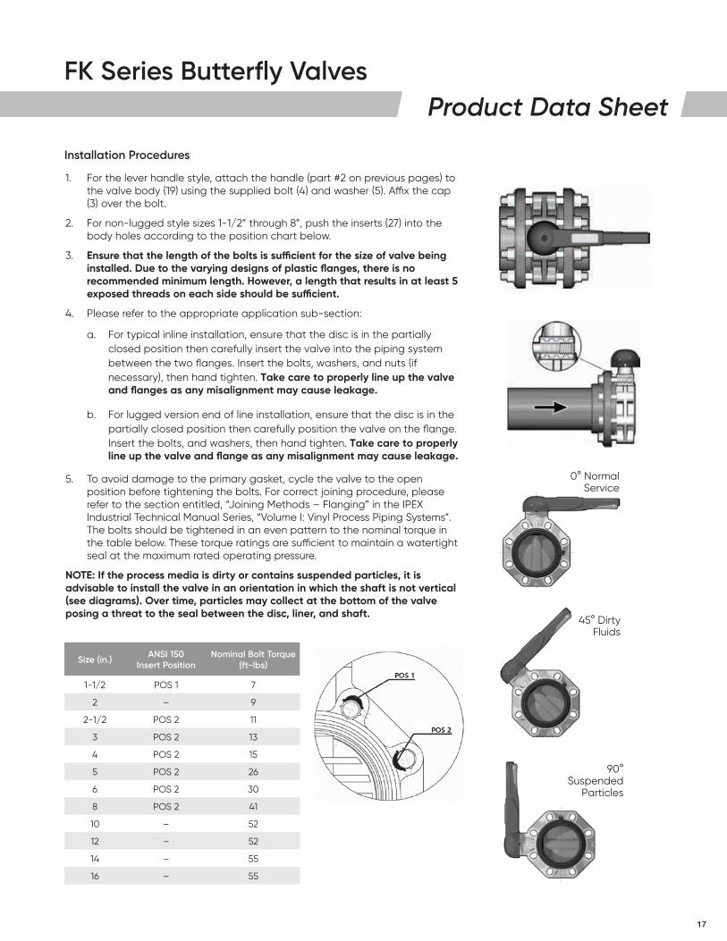
1. For the lever handle style, attach the handle (part #2 on previous pages) to the valve body (19) using the supplied bolt (4) and washer (5). Affix the cap (3) over the bolt.
2. For non-lugged style sizes 1-1/2” through 8”, push the inserts (27) into the body holes according to the position chart below.
3. Ensure that the length of the bolts is sufficient for the size of valve being installed. Due to the varying designs of plastic flanges, there is no recommended minimum length. However, a length that results in at least 5 exposed threads on each side should be sufficient.
4. Please refer to the appropriate application sub-section:
a. For typical inline installation, ensure that the disc is in the partially closed position then carefully insert the valve into the piping system between the two flanges. Insert the bolts, washers, and nuts (if necessary), then hand tighten. Take care to properly line up the valve and flanges as any misalignment may cause leakage.
b. For lugged version end of line installation, ensure that the disc is in the partially closed position then carefully position the valve on the flange. Insert the bolts, and washers, then hand tighten. Take care to properly line up the valve and flange as any misalignment may cause leakage.
5. To avoid damage to the primary gasket, cycle the valve to the open position before tightening the bolts. For correct joining procedure, please refer to the section entitled, “Joining Methods – Flanging” in the IPEX Industrial Technical Manual Series, “Volume I: Vinyl Process Piping Systems”. The bolts should be tightened in an even pattern to the nominal torque in the table below. These torque ratings are sufficient to maintain a watertight seal at the maximum rated operating pressure.
NOTE: If the process media is dirty or contains suspended particles, it is advisable to install the valve in an orientation in which the shaft is not vertical (see diagrams). Over time, particles may collect at the bottom of the valve posing a threat to the seal between the disc, liner, and shaft.
Installation Procedures
0° Normal Service
45° Dirty Fluids
90° Suspended
Particles
Size (in.) ANSI 150 Insert Position
Nominal Bolt Torque (ft-lbs)
1-1/2 POS 1 7
2 – 9
2-1/2 POS 2 11
3 POS 2 13
4 POS 2 15
5 POS 2 26
6 POS 2 30
8 POS 2 41
10 – 52
12 – 52
14 – 55
16 – 55
18
FK Series Butterfly ValvesProduct Data Sheet
The purpose of system testing is to assess the quality of all joints and fittings to ensure that they will withstand the design working pressure, plus a safety margin, without loss of pressure or fluid. Typically, the system will be tested and assessed in sub-sections as this allows for improved isolation and remediation of potential problems. With this in mind, the testing of a specific installed valve is achieved while carrying out a test of the overall system.
An onsite pressure test procedure is outlined in the IPEX Industrial Technical Manual Series, “Volume I: Vinyl Process Piping Systems” under the section entitled, “Testing”. The use of this procedure should be sufficient to assess the quality of a valve installation. In any test or operating condition, it is important to never exceed the pressure rating of the lowest rated appurtenance in the system.
Important points:
• Never test thermoplastic piping systems with compressed air or other gases including air-over-water boosters.
• When testing, do not exceed the rated maximum operating pressure of the valve.
• Avoid the rapid closure of valves to eliminate the possibility of water hammer which may cause damage to the pipeline or the valve.
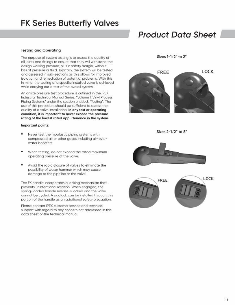
The FK handle incorporates a locking mechanism that prevents unintentional rotation. When engaged, the spring-loaded handle release is locked and the valve cannot be cycled. A padlock can be installed through this portion of the handle as an additional safety precaution.
Please contact IPEX customer service and technical support with regard to any concern not addressed in this data sheet or the technical manual.
Testing and Operating
Sizes 1-1/2” to 2”
Sizes 2-1/2” to 8”
19
About IPEX
This literature is published in good faith and is believed to be reliable. However, it does not represent and/or warrant in any manner the information and suggestions contained in this brochure. Data presented is the result of laboratory tests and field experience.
A policy of ongoing product improvement is maintained. This may result in modifications of features and/or specifications without notice.
FK Series Butterfly Valves
About the IPEX Group of CompaniesAs leading suppliers of thermoplastic piping systems, the IPEX Group of Companies provides our customers with some of the world’s largest and most comprehensive product lines. All IPEX products are backed by more than 50 years of experience. With state-of-the-art manufacturing facilities and distribution centers across North America, we have established a reputation for product innovation, quality, end-user focus and performance.
Markets served by IPEX group products are:
• Electrical systems• Telecommunications and utility piping systems• Industrial process piping systems• Municipal pressure and gravity piping systems• Plumbing and mechanical piping systems• Electrofusion systems for gas and water• Industrial, plumbing and electrical cements• Irrigation systems• PVC, CPVC, PP, PVDF, PE, ABS, and PEX pipe and fittings
ipexna.comToll Free: 866 473-9462
PRO
DSF
K112
020
C