Embed Size (px)
Citation preview
A P T A S T A N D A R D S D E V E L O P M E N T P R O G R A M
STANDARD
American Public Transportation Association
1666 K Street, NW, Washington, DC, 20006-1215
APTA PR-CS-S-018-13, Rev. 1
First Published March 26, 2013
First Revision October 30, 2015
PRESS Construction & Structural Working
Group
This Standard represents a common viewpoint of those parties concerned with its provisions, namely, rail operating/planning agencies, manufacturers, consultants, engineers, and general interest groups. In some cases, federal and/or state regulations govern portions of a transit system’s operations. In those cases, the government regulations take precedence over this standard. .
© 2015 NATSA and its parent organization. No part of this publication may be reproduced in any form, in an electronic retrieval system or otherwise, without the prior written permission of NATSA.
Fixed Workstation Tables in Passenger Rail Cars
Abstract: This Rail Standard defines crashworthiness requirements for fixed workstation tables installed in
passenger rail coach cars that are part of the general railroad system of transportation.
Keywords: crashworthiness, fixed workstation tables, passenger rail, safety
Summary: In passenger rail coach seating configurations with fixed workstation tables, there is a risk of
serious thoracic and abdominal injury when passengers impact a table during a rail accident. Tables designed
to absorb energy and limit contact forces can significantly reduce the risk of injury. Additionally, tables
positioned between facing rows of seats can serve to compartmentalize occupants during a collision, which
can limit secondary impact velocity and prevent tertiary impacts with other objects or passengers.
Scope and purpose: This standard, which improves passenger collision safety, applies to new railcar
procurements and is intended to provide guidance for the design and testing of fixed workstation tables used
in passenger rail cars. This standard applies to fixed workstation tables that are positioned at revenue seats in
any type of passenger car but does not apply to fold-down seatback tables nor to tables in sleeping car rooms.
Portions of this standard are intended to provide details on how to demonstrate compliance with the
requirements of 49 CFR Part 238.233, Interior Fittings and Surfaces. The purpose of this standard is to define
requirements for workstation tables that result in reduced injuries and fatalities due to table impacts during
passenger rail accidents.

© 2015 American Public Transportation Association | ii
Participants The American Public Transportation Association greatly appreciates the contributions of the PRESS Construction & Structural Working Group and its Workstation Table Sub-Working Group, which provided the primary effort in the drafting of this Rail Standard.
At the time this standard was completed, the sub working group included the following members:
Kristine Severson, Chair
Allen C. Bieber Gordon Campbell Dominique LeCorre Gene Germaine Jeffrey Gordon Daniel Gornstein Virgilo Hilario Ritch Hollingsworth Tom Hunt C. Hunter Paul Jamieson T. Kakaris Kevin Kesler William Luebke Frank Maldari Eloy Martinez Peter Matthews Michelle Muhlanger Anand Prabhakaran Steven Roman David Tyrell Christopher Wasilewski Gary Widell Project Team Martin Schroeder American Public Transportation Association
Contents
1. Overview .............................................................................................. 1
2. Table attachment requirements ........................................................ 1 2.1 Attachment strength ..................................................................... 1 2.2 Mounting hardware ...................................................................... 2
3. Table geometry requirements ........................................................... 2
4. Operational testing ............................................................................. 3
5. Crashworthiness testing ................................................................... 3 5.1 Option A: Dynamic sled test with Hybrid IIIRS or THOR ATD 4 5.2 Option B: Dynamic sled test with standard HIII ATD coupled
with quasi-static testing ..................................................................... 7
6. Test implementation plan, procedures and report ....................... 11 6.1 Test implementation plan .......................................................... 12 6.2 Test procedures .......................................................................... 12 6.3 Test reports ................................................................................ 12
7. Flammability and smoke emission ................................................. 13
8. Engineering drawings ...................................................................... 13
9. Submittals for approval ................................................................... 13
10. Procurement specifications .......................................................... 14
Other related APTA Standards ............................................................ 14
References ............................................................................................ 14
Bibliography .......................................................................................... 14
Definitions ............................................................................................. 15
Abbreviations and acronyms .............................................................. 17
Summary of changes ......................................................................... 188
Document history ................................................................................. 18

APTA PR-CS-S-018-13, Rev. 1 Fixed Workstation Tables in Passenger Rail Cars
© 2015 American Public Transportation Association 1
Fixed Workstation Tables in Passenger Rail Cars
1. Overview In passenger rail seating configurations with fixed workstation tables, there is a risk of serious thoracic and
abdominal injury when passengers impact a table during a rail accident [1, 2]. Tables designed to absorb
energy and limit contact forces can significantly reduce the risk of injury. Additionally, tables positioned
between facing rows of passenger seats can serve to compartmentalize occupants during a collision, which
can limit secondary impact velocity and prevent tertiary impacts with other objects or passengers.
This standard defines crashworthiness requirements for fixed workstation tables installed in passenger rail
cars that are part of the general railroad system of transportation. This standard applies to fixed workstation
tables that are positioned at revenue seats in any type of passenger car but does not apply to fold-down
seatback tables nor tables in sleeping car rooms. This safety standard applies to the procurement of
workstation tables for new passenger rail cars and describes the tests and table performance requirements
necessary to demonstrate compliance with this standard. This standard becomes effective on the date of
authorization stated on the title page.
The requirements listed here are derived in part from industry and federal requirements. These requirements
are contained in the Code of Federal Regulations, Title 49, Part 238, Section 233; and the United Kingdom
Railway Group Standard GM/RT2100 Issue 4. Maximum allowable injury criteria values are derived from the
Code of Federal Regulations, Title 49, Part 571, Section 208; GM/RT2100 Issue 4; and research results
sponsored by the Federal Railroad Administration Office of Research and Development [3, 4].
2. Table attachment requirements
2.1 Attachment strength
A workstation table is considered to be an interior fitting and is subject to the attachment strength
requirements in the Code of Federal Regulations, Title 49, Part 238, Section 233 Article (c). This section is
intended to provide additional guidance in satisfying these CFR requirements.
The Code of Federal Regulations, Title 49, Part 238, Section 233 Article (c) specifies the following:
Other interior fittings within a passenger car shall be attached to the carbody with sufficient strength to
withstand the following individually applied accelerations acting on the mass of the fitting:
Longitudinal: 8g;
Vertical: 4g; and
Lateral: 4g.
The equivalent loads in Article (c) may be applied quasi-statically or dynamically. If the load is applied
dynamically, then the acceleration time history shall have a duration of 250 ms and a peak of 4g in the lateral
and vertical direction, and 8g in the longitudinal direction, with the peaks occurring at 125 ms; an example of
the 8g crash pulse is shown in Figure 3.

APTA PR-CS-S-018-13, Rev. 1 Fixed Workstation Tables in Passenger Rail Cars
© 2015 American Public Transportation Association 2
2.2 Mounting hardware
The hardware used to attach the table to the carbody shall conform to the Code of Federal Regulations, Title
49, Part 238, Section 233 Article (d), as appropriate: To the extent possible, all interior fittings in a passenger
car, except seats, shall be recessed or flush-mounted.
3. Table geometry requirements The table design geometry shall minimize points of entrapment and concentrated loading points (associated
with sharp radii) during a rail vehicle accident. The table shall compartmentalize occupants between the
occupied seat and the table in the event of an accident.
The inboard corners of the table edge shall be rounded to a minimum radius of 1 in. (2.54 cm). The edges of
the table’s top and bottom shall be rounded to a minimum radius of 3⁄16 in. (0.5 cm) around the entire
perimeter. Laterally, the table shall begin at the wall or no more than 2 in. (5.08 cm) inboard of the outboard
edge of the window seat base and extend to the inboard edge of the aisle seat base, or no more than 2 in.
(5.08 cm) from the inboard edge of the aisle seat. See Figure 1 for a schematic of the geometry
measurements. While Figure 1 depicts tables at one- and two-passenger seats, the same geometry
requirements apply to tables located at three-passenger seats, or tables installed between a single seat and a
double seat, or between a double and a triple seat. In the latter two cases, the table must extend to within 2 in.
of the wider seat, per the schematic below. A tapered tabletop is permissible if it meets all the testing
requirements in this standard.
If Option B is used in Section 5.2 to demonstrate compliance with the crashworthiness requirements, then the
edge of the tabletop must be at least 2.0 in. thick. This additional requirement is intended to minimize
concentrated abdominal loads in the event of a collision. This table thickness requirement is applied to Option
B only because neither the dynamic sled test with standard 50th percentile anthropomorphic test device
(ATD), nor the quasi-static loading test, is capable of assessing abdominal injury associated with overly
concentrated loads.
FIGURE 1 Geometry Measurements, Top View

APTA PR-CS-S-018-13, Rev. 1 Fixed Workstation Tables in Passenger Rail Cars
© 2015 American Public Transportation Association 3
4. Operational testing The objective of the operational testing is to demonstrate that the operational loads do not cause damage to
the table that would prevent it from functioning as intended in a collision.
The table and its support structure shall be designed and tested to meet the individually applied quasi-static
load requirements given below with no permanent yielding of structural materials, or loss of function, or
change in appearance of the table or support structure. A small amount of yielding due to relieving of trapped
manufacturing stresses (welding, forming, etc.) shall be permissible; however, there shall be no visible
indication of permanent deformation.
The table shall be mounted on a rigid test fixture or simulated car structure using the same fasteners or
attachment mechanism used in service — bolts, screws, seat track, tapping plate, etc. The tabletop shall not
experience permanent deformation under the following individually applied load conditions:
a. Minimum 225 lbf (1000 N) load applied on a 5 × 5 in. area (±0.25 in.) in a vertical downward
direction at a location on the top of the table that represents the worst-case loading condition,
generally at a point farthest away from the table support structure. The load shall be applied for a
minimum of 5 s.
b. Minimum 337 lbf (1500 N) load applied on an 8 in.(±0.25 in.) length across the full thickness of the
tabletop in a longitudinal direction at a location on the table edge that represents the worst-case
condition, generally at a point farthest away from the table support structure. The load shall be
applied for a minimum of 5 s.
5. Crashworthiness testing The objectives of crashworthiness testing are to demonstrate the following:
The table effectively absorbs kinetic energy, while limiting the contact force between the occupants
and the table.
The table remains attached to the test sled or fixture.
The table effectively compartmentalizes the occupants.
The table effectively limits human injury of the head, chest, neck, abdomen and femurs.
Table deformation does not expose occupants to sharp edges or spaces capable of entrapping an
occupant during a rail accident.
Table components that exceed the material yield strength shall display post-yield plasticity.
Two options are provided below to demonstrate that a particular table design complies with these
crashworthiness objectives. The test(s) shall be conducted in accordance with the requirements given in
Section 5.1 for Option A or Section 5.2 for Option B.
If a structurally identical table installed in a similar physical arrangement (see Section 6 for maximum
variances allowed) has been tested in accordance with the requirements of this standard, then at the discretion
of the purchaser and in lieu of added testing, the manufacturer may provide test data in accordance with
Section 6 of this document to demonstrate that the table is in compliance with all the requirements of this
standard.

APTA PR-CS-S-018-13, Rev. 1 Fixed Workstation Tables in Passenger Rail Cars
© 2015 American Public Transportation Association 4
5.1 Option A: Dynamic sled test with Hybrid IIIRS or THOR ATD
A dynamic sled test shall be conducted in accordance with the conditions given in Section 5.1.1. The required
test measurements and documentation are given in Section 5.1.2. The workstation table shall comply with all
the performance requirements listed in Section 5.1.3.
5.1.1 Dynamic sled test conditions
A workstation table shall be mounted on a simulated car structure or rigid test fixture using the same fasteners
or attachment mechanism used in service — bolts, screws, track, tapping plate, etc. If the table is fastened
directly to a rigid test fixture, then tri-axial load cells shall be placed at the table mounting locations between
the table and the test fixture to measure reaction loads applicable to structural car design for the purpose of
confirming the adequacy of the carbody structure to accommodate these loads without failure. The application
of load cells must not, however, affect performance of the fastening device.
A passenger seat shall be mounted to the test sled at the nominal location relative to the table for the intended
rail service. A facing seat is not required to be mounted on the opposite side of the table; however, a means of
evaluating potential intrusion of the workstation table toward a facing seat must be provided. Instrumented
anthropomorphic test devices (ATDs), representative of 50th-percentile adult males, shall be positioned to
face the direction of travel, such that all seats are simultaneously occupied by ATDs. At least one ATD shall
be a Hybrid IIIRS [5], or Test device for Human Occupant Restraint (THOR) [6], that is capable of measuring
compression and rates of compression of the abdomen and chest, and for calculating the injury criteria listed
in Section 5.1.2 below.
If only one Hybrid IIIRS or THOR ATD is available, then that ATD shall be placed in the seat position
nearest the wall. A standard HIII 50th-percentile male ATD, in accordance with 49 CFR 572, Subpart E, may
be used in the other seat position(s). An ATD shall be positioned at the table in each available seat, facing the
direction of travel.
The adjustment, positioning and care of all ATDs used in the testing processes shall be in accordance with the
standards and requirements needed to comply with SAE standard AS8049, “Performance Standards for
Single-Occupant, Side-Facing Seats in Civil Rotorcraft, Transport Aircraft, and General Aviation Aircraft.”
Each ATD shall be clothed in a form-fitting cotton stretch garment with short sleeves and mid-thigh-length
bottoms. The ATDs shall also be fitted with shoes. Each ATD shall be centered in the seat, in as nearly
symmetrical a position as possible and in a uniform manner so as to obtain reproducible test results. The
following ATD components shall be positioned as follows:
Back shall be placed against the seat back without clearance.
Knees shall be separated by 4 in.
Hands shall be placed on the thighs, palms down, as shown in Figure 2.
Feet shall be placed flat on the floor so that the centerlines of the lower legs are approximately
parallel.
Lower legs shall be placed as close to vertical as possible.
The ATDs may be tethered to the sled; however, tethering shall not restrict ATDs such that evaluation of
compartmentalization is impeded.
If a test fixture is used instead of a carbody section, then the fixture shall act as a rigid mounting point for the
table and seats. See Figure 2 for a schematic of the sled configuration. The test sled shall be subjected to an
8g, 250 ms crash pulse, as shown in Figure 3. The measured crash pulse shall comply with the requirements

APTA PR-CS-S-018-13, Rev. 1 Fixed Workstation Tables in Passenger Rail Cars
© 2015 American Public Transportation Association 5
established in SAE AS8049 Revision A, Appendix A, to determine that the actual pulse is within accepted
tolerance parameters.
FIGURE 2 Schematic of Sled Configuration
FIGURE 3 Longitudinal Crash Pulse
5.1.2 Dynamic sled test measurement and documentation requirements
The following data shall be obtained for each ATD during the test in accordance with SAE J211/1:
triaxial head acceleration-time history
triaxial chest acceleration-time history
axial left and right femur force-time history
upper neck extension/flexion bending moment, My time history
upper neck axial force, Fz time history
upper neck shear force, Fx time history
chest compression-time history
abdominal compression-time history
longitudinal acceleration-time history of the test sled
triaxial load cell force-time history, if load cells are used to measure reaction loads
The following measurements, which are needed for information related to potential configuration
modification allowances provided in Section 6, shall be taken before the test (pre-test):
Longitudinal distance (in a horizontal plane) between the front edge of the tabletop and the seat back
on the side of the ATDs (depicted as measurement “A” in Figure 4).
Vertical distance between top of tabletop and the highest point on the seat bottom cushion (depicted
as measurement “B” in Figure 4). If a facing seat is not used, then the measurement may be taken on
the launch seat, before the ATD is placed in the seat.
The following measurement shall be taken after testing (post-test):
Test Sled AccelerationTest Sled Acceleration
0
2
4
6
8
10
0 125 250
Time (ms)
Accel
(g)

APTA PR-CS-S-018-13, Rev. 1 Fixed Workstation Tables in Passenger Rail Cars
© 2015 American Public Transportation Association 6
Longitudinal distance (in a horizontal plane) between the front edge of the tabletop and the seat back
on the side opposite the ATDs (depicted as measurement “C” in Figure 4). If a facing seat is not
used, then measurement “C” shall be calculated using the theoretical position of the facing seat.
The following injury criteria shall be computed for each ATD (per the definitions described at the end of this
document):
head injury criterion (HIC15)
3 ms chest g’s
axial femur load
upper neck axial tension/compression loads
neck injury criterion (Nij)
chest compression
chest viscous criterion (VC)
abdominal compression
abdominal viscous criterion (VC)
Unless otherwise indicated, instrumentation for data acquisition, data channel frequency class and moment
calculations are the same as those given for the 49 CFR Part 572, Subpart E, Hybrid III Anthropomorphic
Test Device.
The test shall be captured using high-speed video cameras providing an overhead view (plan view) and a side
view (elevation view). Lighting shall be sufficient for high-quality analysis of the recording. Pre- and post-
test still digital photographs of the test configuration shall be taken. At a minimum, photographs of the test
sled should be taken from all four sides, as well as close-up photographs of the seats and tables to document
any damage.
5.1.3 Dynamic sled test performance requirements
For a successful test, the following requirements must be met:
1. The table and any table components must remain attached to the test fixture or simulated rail car
structure, with the exception of superficial, nonstructural components of negligible weight.
2. The table shall not penetrate the survival space reserved for occupants in the facing seat, where
applicable, so as not to entrap the facing passengers or prevent egress. The survival space, as depicted
by measurement “C” in Figure 4 and Figure 5, shall not be less than 15 in., as measured post-test
(theoretical location if facing seat is not used in actual test) using predominant seat pitch for seats
surrounding tables.
3. The ATDs shall be compartmentalized, as defined in the definitions at the end of this document.
4. All injury measurements computed in Section 5.1.2 must meet the following criteria, which are
defined at the end of this standard:
• Head injury criterion, HIC15, shall be less than 700*.
• Neck injury criterion, Nij, shall be less than 1.0*.
• Neck axial tension, Fz, shall be less than 938 lbf (4170 N)*.
• Neck axial compression, Fz, shall be less than 899 lbf (4000 N)*.
• Chest deceleration shall be less than 60g over a 3 ms clip*.
• Chest compression shall be less than 2.5 in. (63 mm)*.
• Chest viscous criterion shall be less than 1.0 m/s+.
• Abdominal compression shall be less than 2.6 in. (67 mm)+
• Abdominal viscous criterion shall be less than 1.98 m/s+.
• Axial femur load shall be less than 2250 lbf (10,000 N)*.

APTA PR-CS-S-018-13, Rev. 1 Fixed Workstation Tables in Passenger Rail Cars
© 2015 American Public Transportation Association 7
NOTE: Items marked with * were originally derived from 49 CFR 571.208. Items marked with + were
originally derived from GM/RT2100, Issue 4.
FIGURE 4 Schematic Depicting Pre- and Post-Test Measurements
FIGURE 5 Schematic Depicting Measurement Locations
5.2 Option B: Dynamic sled test with standard HIII ATD coupled with quasi-static testing
Option B may not be used to demonstrate compliance for tables with an edge thickness less than 2.0 in.
(50 mm). Thinner tables must conform to the requirements in Option A. Option B may not be used to
demonstrate compliance for adjustable tables. Adjustable tables must conform to the requirements in
Option A.
1
C
B
A

APTA PR-CS-S-018-13, Rev. 1 Fixed Workstation Tables in Passenger Rail Cars
© 2015 American Public Transportation Association 8
If Option B is selected to demonstrate table crashworthiness, then the following two tests shall be conducted:
a dynamic sled test with standard HIII 50th percentile male ATDs; and
a quasi-static destructive loading test.
The purpose of the dynamic sled test is to demonstrate that:
the table remains attached to the test sled;
the table effectively compartmentalizes the occupants; and
the table effectively limits human injury for the head, chest, neck and femurs.
The purpose of the quasi-static test is to demonstrate that:
the table effectively absorbs kinetic energy, while limiting the contact force between the occupants
and the table. The performance requirements for this test were chosen to limit human injury to the
abdomen.
5.2.1 Dynamic sled test
The test conditions, measurement and documentation requirements, and performance requirements for the
Option B dynamic sled test are described in this section.
5.2.1.1 Dynamic sled test conditions
The dynamic sled test for Option B shall be conducted according to the test conditions in Section 5.1.1,
except that the ATDs shall all be standard HIII 50th percentile male ATDs, in accordance with 49CFR572,
Subpart E.
5.2.1.2 Dynamic sled test measurements and documentation requirements
The measurement and documentation requirements for Option B shall follow the instructions provided for
Option A in Section 5.1.2, with the exception of abdominal compression time history and injury criteria for
abdominal compression and the abdominal viscous criterion.
5.2.1.3 Dynamic sled test performance requirements
The performance requirements for Option B shall follow the instructions provided for Option A in Section
5.1.3, with the exception of injury criteria requirements for abdominal compression and the abdominal
viscous criterion.
5.2.2 Quasi-static test
The test conditions, measurement and documentation requirements, and performance requirements for the
Option B quasi-static test are described in this section.
5.2.2.1 Quasi-static test conditions
The quasi-static loading test is subject to the following conditions. A workstation table shall be mounted on a
rigid test fixture or simulated car structure using the same fasteners or attachment mechanism used in service
— bolts, screws, track, tapping plate, etc. The workstation table shall be destructively tested under quasi-static
loading conditions.
The quasi-static test shall be conducted with the loads applied to the table simultaneously via rigid body
blocks (depicted in Figure 6), one at each seat position, to which hydraulic cylinders shall be attached (see
Figure 7 for a schematic of the test setup). The body blocks shall be aligned laterally at the center of each seat

APTA PR-CS-S-018-13, Rev. 1 Fixed Workstation Tables in Passenger Rail Cars
© 2015 American Public Transportation Association 9
position for the intended service. The body blocks shall be centered vertically on the table edge. The
displacement rate of the cylinders shall be approximately 2 in./min. The motion of each hydraulic cylinder
shall be stopped independently when the individually applied load at a single seat position exceeds 2250 lbf,
or when the maximum table crush has been achieved, whichever comes first.
FIGURE 6 Body Block (dimensions are in inches)
FIGURE 7 Schematic of Test Setup

APTA PR-CS-S-018-13, Rev. 1 Fixed Workstation Tables in Passenger Rail Cars
© 2015 American Public Transportation Association 10
5.2.2.2 Quasi-static test measurements and documentation requirements
The force-time history and displacement-time history of each loading ram shall be measured. The longitudinal
displacement of the tabletop shall be measured on the side opposite the load applications in line with the
applied loads using string potentiometers (see Figure 7).
The table penetration into the passenger space on the opposite side of the table shall be calculated by
subtracting the longitudinal deflection of the table (measured by string potentiometers) from the initial
theoretical longitudinal distance between the table edge and the seat back.
The energy absorbed by table deformation at each table position shall be calculated as follows:
Plot the table deflection vs. time, where deflection is equal to the displacement of the loading ram,
from t0 to tf, where:
- t0 = time that ram contacts the table; and
- tf = time that force returns to zero.
Cross-plot the force vs. deflection time history from t0 to tf.
Integrate the force vs. deflection time history from t0 to tf to calculate the energy absorbed by plastic
(permanent) table deformation at each seat position.
Still photographs of the table shall be taken pre- and post-test. The progress of the test shall also be recorded
using a digital video camera at two locations (top and side views).
5.2.2.3 Quasi-static test performance requirements
For a successful test, the following requirements must be met:
1. The table and any table components must remain attached to the test fixture or simulated rail car
structure, with the exception of superficial, nonstructural components of negligible weight.
2. The table shall not penetrate the survival space reserved for occupants in the facing seat, where appli-
cable, so as not to entrap the facing passengers or prevent egress. The survival space, as depicted by
measurement “C” in Figure 4 and Figure 5, shall not be less than 15 in., as measured post-test (theo-
retical location if facing seat is not used in actual test) using predominant seat pitch for seats sur-
rounding tables.
3. The energy absorbed by plastic (permanent) deformation at each seat position, as calculated above,
must be at least 6250 in.-lbf when the applied load reaches 2250 lbf, or when the maximum table
crush has been achieved, whichever comes first.

APTA PR-CS-S-018-13, Rev. 1 Fixed Workstation Tables in Passenger Rail Cars
© 2015 American Public Transportation Association 11
FIGURE 8 Schematic Depicting Minimum Space Requirement
6. Test implementation plan, procedures and report All testing performed by the table manufacturer shall be documented with a test plan, test procedures and test
report. The test implementation plan and test procedures should be submitted and approved by the purchaser
prior to actual testing. Tests should be scheduled to allow the purchaser to witness the testing. The purchaser
may elect to accept existing test reports and procedures, provided that the table to be purchased is
demonstrated to be structurally identical to that tested and that the test reports and procedures meet the
requirements listed below.
If a structurally identical table design had been tested in a specific configuration and met all the requirements
of this standard, then it does not need to be retested for a different installation configuration if all the
parameter modifications are within the defined acceptable tolerance range below:
1. Longitudinal distance (in a horizontal plane) between the front edge of the tabletop and the seat back
(depicted as measurement “A” in Figure 4): +1/-3 in.
2. Vertical distance between top of tabletop and the highest point on seat bottom cushion (depicted as
measurement “B” in Figure 4): ±1 in.
It may be desirable to manufacture a table with slightly different tabletop geometry for different applications.
If minor geometrical changes are made to an otherwise structurally identical table design that had been tested
and met all the requirements of this standard, then it does not need to be retested if geometry changes are
within the defined acceptable tolerance range below:
1. Tabletop length: +1/-3 in.
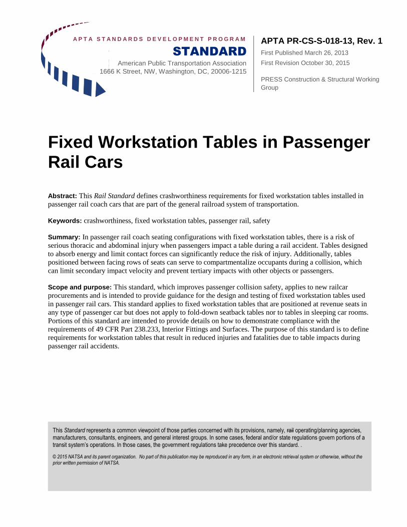
2. Tabletop width: +3/-0 in. (see schematic in Figure 9).
>15”>15”
APTA PR-CS-S-018-13, Rev. 1 Fixed Workstation Tables in Passenger Rail Cars
© 2015 American Public Transportation Association 12
FIGURE 9 Schematic of Tabletop Geometry Definitions
6.1 Test implementation plan
The test implementation plan shall describe how the tests will be conducted, including a description of the test
fixtures, instrumentation and data acquisition system. Prior to table testing, a test plan shall be submitted by
the table manufacturer to the purchaser. The final test plan shall be reviewed and approved by the purchaser.
6.2 Test procedures
A set of test procedures for each test shall be prepared by the table manufacturer and submitted for approval
to the purchaser. The test procedures shall as a minimum include the following:
test objective
complete description of test article
pass/fail criteria
list of test equipment
schematic illustration(s) of test setup
description of the attachment of the table to the text fixture/load cells
time and location of tests
sequential, step-by-step test procedure
test data sheets (for recording data during testing)
drawing of the assembled seats depicting all dimensions of the assembly, with references to the floor
and adjacent facing seats and table
6.3 Test reports
Test reports shall as a minimum include the following:
test requirements
text or cover letter that provides a summary of the test results, the date and location of the test, and
the signature of the person or people responsible for conducting the test and writing the report
calibration data for all test measuring equipment
pre- and post-test measurements (dimensions, etc.)
width
length
APTA PR-CS-S-018-13, Rev. 1 Fixed Workstation Tables in Passenger Rail Cars
© 2015 American Public Transportation Association 13
calculated injury criteria, per test requirements
graphical output of all data channels
test videos
pre- and post-test photos
7. Flammability and smoke emission Materials used in table construction shall meet the requirements given in 49 CFR Part 238, Appendix B.
8. Engineering drawings As part of its work and prior to the supply of tables, the table manufacturer shall submit engineering drawings
for approval. The drawings shall, at a minimum, include the following:
overall dimensions and tolerances of the table assembly
weight and location of the center of gravity of the table assembly
mounting requirements including hole sizes, recommended bolt sizes and torque requirements, and
recommended grade of bolts to be used for mounting
description of materials
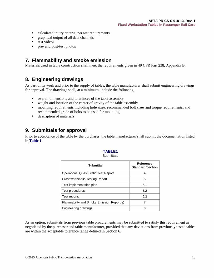
9. Submittals for approval Prior to acceptance of the table by the purchaser, the table manufacturer shall submit the documentation listed
in Table 1.
TABLE1 Submittals
Submittal Reference
Standard Section
Operational Quasi-Static Test Report 4
Crashworthiness Testing Report 5
Test implementation plan 6.1
Test procedures 6.2
Test reports 6.3
Flammability and Smoke Emission Report(s) 7
Engineering drawings 8
As an option, submittals from previous table procurements may be submitted to satisfy this requirement as
negotiated by the purchaser and table manufacturer, provided that any deviations from previously tested tables
are within the acceptable tolerance range defined in Section 6.

APTA PR-CS-S-018-13, Rev. 1 Fixed Workstation Tables in Passenger Rail Cars
© 2015 American Public Transportation Association 14
10. Procurement specifications This standard is intended to be supplemented by procurement specifications prepared by the purchaser and
directed to the table manufacturer.
Related APTA Standards APTA-PR-CS-S-006-98 Rev 1, Standard for Attachment Strength of Interior Fittings for Passenger
Rail Road Equipment
APTA PR-I&M-RP-002-98: “Development Model for Rail Car Technical Documentation”
References This standard shall be used in conjunction with the following publications. When the following standards are
superseded by an approved revision, the revision shall apply.
49 CFR Part 238, Section 103: Fire Safety
49 CFR Part 238, Section 233: Interior Fittings and Surfaces
49 CFR Part 571, Section 208: Federal Motor Vehicle Safety Standards
49 CFR Part 572: Anthropomorphic Test Devices
SAE J211-1, Instrumentation for Impact Test - Part 1 - Electronic Instrumentation
SAE AS8049, Performance Standard for Seats in Civil Rotorcraft, Transport Aircraft, and General
Aviation Aircraft
GM/RT2100, Issue Four, Requirements for Rail Vehicle Structures, Railway Group Standard , United
Kingdom, Rail Safety and Standards Board Ltd., December 2010
Bibliography 1. Parent, D., Tyrell, D., Perlman, A.B., “Evaluating Abdominal Injury in Workstation Table Impacts,”
Compendium of Papers, 84th Annual Meeting, Transportation Research Board, January 2005.
2. Parent, D., Tyrell, D., Perlman, A.B., “Crashworthiness Analysis of the Placentia, CA Rail Collision,”
Proceedings of ICrash 2004, International Crashworthiness Conference, San Francisco, California, July
14-16, 2004.
3. Severson, K., Perlman, A.B., Muhlanger, M., Stringfellow, R., “Evaluation of Testing Methods to
Develop Test Requirements for a Workstation Table Safety Standard,” American Society of Mechanical
Engineers, Paper No. RTDF2010-42032, October 2010.
4. Muhlanger, M., Parent, D., Severson, K., Perlman, A.B., “Development of Performance Requirements for
a Rail Passenger Workstation Table Safety Standard,” American Society of Mechanical Engineers, Paper
No. RTDF2010-42031, October 2010.
5. Rail Safety Standards Board, Hybrid III Rail Dummy Specification.
http://www.rssb.co.uk/pages/research-catalogue/pb009352.aspx.
6. Haffner, M., et al., “Foundations and Elements of the NHTSA THOR Alpha ATD Design,” Paper 458,
presented at the 17th International Technical Conference on the Enhanced Safety of Vehicles,
Amsterdam, Holland.

APTA PR-CS-S-018-13, Rev. 1 Fixed Workstation Tables in Passenger Rail Cars
© 2015 American Public Transportation Association 15
7. Parent, D., Tyrell, D., Rancatore, R., Perlman, A.B., “Design of a Workstation Table with Improved
Crashworthiness Performance,” American Society of Mechanical Engineers, Paper No. IMECE2005-
82779, November 2005.
8. Severson, K., Parent, D., “Train-to-Train Impact Test of Crash Energy Management Passenger Rail
Equipment: Occupant Experiments,” American Society of Mechanical Engineers, Paper No.
IMECE2006-14420, November 2006.
9. Tyrell, D.C., Severson, K.J., Marquis, B.J., “Analysis of Occupant Protection Strategies in Train
Collisions,” American Society of Mechanical Engineers, AMD-Vol. 210, BED-Vol. 30, pp. 539-557,
1995.
10. VanIngen-Dunn, C., “Commuter Rail Seat Testing and Analysis of Facing Seats,” U.S. Department of
Transportation, DOT/FRA/ORD-03/06, December 2003.
11. Stringfellow, R., Rancatore, R., “Workstation Table Engineering Model, Design, Development,
Fabrication, and Testing,” U.S. Department of Transportation, DOT/FRA/ORD-12-06, May, 2012.
12. Stringfellow, R., Nutting, J., “Workstation table Crashworthiness Tests,” U.S. Department of
Transportation, DOT/FRA/ORD-13/48, December, 2013.
Definitions abdominal compression criterion: Peak x-axis deflection measured at each abdominal sensor, filtered at
CFC600.
abdominal viscous criterion (VC): A value calculated according to the following formula, using the x-axis
data from each abdominal sensor, filtered at CFC600:
Abdominal VC = V(t) × C(t),
where
V(t) = instantaneous abdominal velocity (m/s)
C(t) = instantaneous abdominal compression ratio, C(t)=D(t)/DAB
D(t) = instantaneous abdominal compression (mm)
DAB = depth of the uncompressed abdomen test device (mm)
adjustable tables: Fixed tables that have moveable parts, such as a hinged or sliding portion of the tabletop,
designed for improved ingress/egress.
axial femur load criterion: Peak axial femur load (Fz), filtered at CFC600.
chest compression criterion: Peak x-axis deflection measured at the sternum, filtered at CFC600.
chest deceleration criterion: The resultant chest deceleration, filtered at CFC1000, shall not exceed 60g,
except for intervals whose cumulative duration is not more than 3 ms.
APTA PR-CS-S-018-13, Rev. 1 Fixed Workstation Tables in Passenger Rail Cars
© 2015 American Public Transportation Association 16
chest viscous criterion (VC): A value calculated according to the following formula, using the x-axis data
measured at the sternum, filtered at CFC600:
Chest VC = 1.3 × V(t) × C(t)
where
V(t) = instantaneous chest velocity (m/s)
C(t) = instantaneous chest compression ratio, C(t) = D(t) / 229
D(t) = instantaneous chest compression in mm.
coach seating: Revenue seats in rail passenger coach cars and cab cars, in all classes of service — business,
first, coach, economy, etc.
compartmentalization: An interior design strategy that aims to contain occupants between rows of seats or
between seats and tables during a collision, preventing occupants from traveling over seats or tables and
impacting other passengers and hostile objects. During sled testing, ATD compartmentalization is evaluated
up until the point of maximum forward progress of the ATD. The ATD must be confined between the
workstation table (potentially deformed) and the initially occupied seat until the ATD begins to rebound and
move away from the impacted table.
facing seats: Adjacent rows of passenger rail coach seats where one row of seats is facing forward and one
row of seats is facing backward. These seating configurations are referred to as face-to-face seats, or open-bay
seats when a workstation table is not present.
fixed tables: Tables that are permanently affixed to the rail car. Tray tables attached to seatbacks are not
considered to be fixed tables and are not subject to the requirements of this standard.
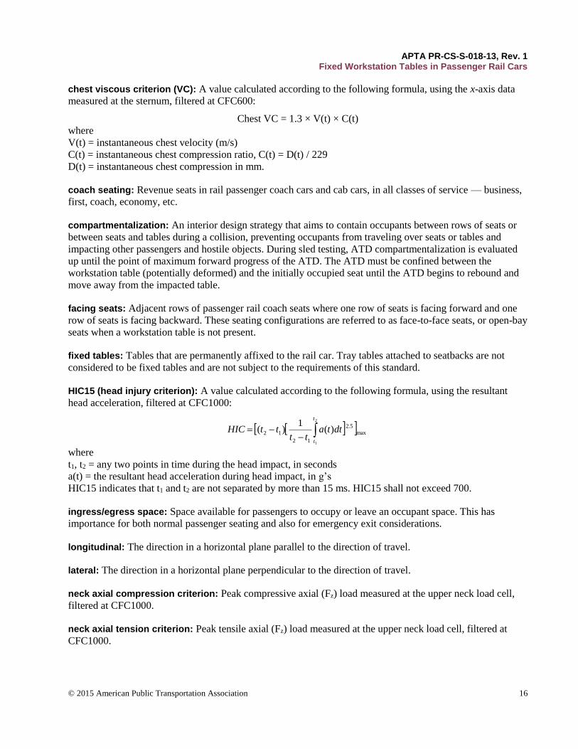
HIC15 (head injury criterion): A value calculated according to the following formula, using the resultant
head acceleration, filtered at CFC1000:
2
1
max
5.2
12
12 )(1
)(
t
t
dttatt
ttHIC
where
t1, t2 = any two points in time during the head impact, in seconds
a(t) = the resultant head acceleration during head impact, in g’s
HIC15 indicates that t1 and t2 are not separated by more than 15 ms. HIC15 shall not exceed 700.
ingress/egress space: Space available for passengers to occupy or leave an occupant space. This has
importance for both normal passenger seating and also for emergency exit considerations.
longitudinal: The direction in a horizontal plane parallel to the direction of travel.
lateral: The direction in a horizontal plane perpendicular to the direction of travel.
neck axial compression criterion: Peak compressive axial (Fz) load measured at the upper neck load cell,
filtered at CFC1000.
neck axial tension criterion: Peak tensile axial (Fz) load measured at the upper neck load cell, filtered at
CFC1000.
APTA PR-CS-S-018-13, Rev. 1 Fixed Workstation Tables in Passenger Rail Cars
© 2015 American Public Transportation Association 17
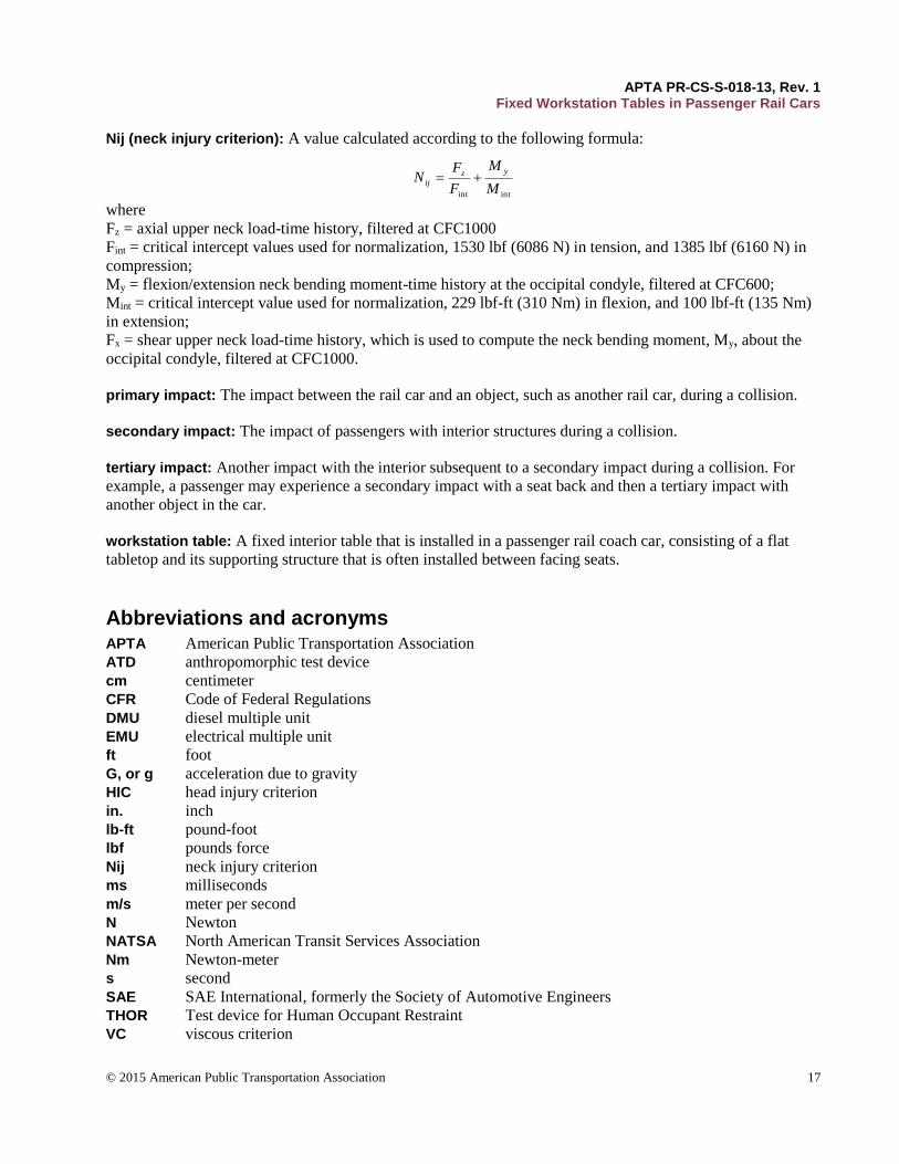
Nij (neck injury criterion): A value calculated according to the following formula:
intint M
M
F
FN
yzij
where
Fz = axial upper neck load-time history, filtered at CFC1000
Fint = critical intercept values used for normalization, 1530 lbf (6086 N) in tension, and 1385 lbf (6160 N) in
compression;
My = flexion/extension neck bending moment-time history at the occipital condyle, filtered at CFC600;
Mint = critical intercept value used for normalization, 229 lbf-ft (310 Nm) in flexion, and 100 lbf-ft (135 Nm)
in extension;
Fx = shear upper neck load-time history, which is used to compute the neck bending moment, My, about the
occipital condyle, filtered at CFC1000.
primary impact: The impact between the rail car and an object, such as another rail car, during a collision.
secondary impact: The impact of passengers with interior structures during a collision.
tertiary impact: Another impact with the interior subsequent to a secondary impact during a collision. For
example, a passenger may experience a secondary impact with a seat back and then a tertiary impact with
another object in the car.
workstation table: A fixed interior table that is installed in a passenger rail coach car, consisting of a flat
tabletop and its supporting structure that is often installed between facing seats.
Abbreviations and acronyms APTA American Public Transportation Association
ATD anthropomorphic test device
cm centimeter
CFR Code of Federal Regulations
DMU diesel multiple unit
EMU electrical multiple unit
ft foot
G, or g acceleration due to gravity
HIC head injury criterion
in. inch
lb-ft pound-foot
lbf pounds force
Nij neck injury criterion
ms milliseconds
m/s meter per second
N Newton
NATSA North American Transit Services Association
Nm Newton-meter
s second
SAE SAE International, formerly the Society of Automotive Engineers
THOR Test device for Human Occupant Restraint
VC viscous criterion

APTA PR-CS-S-018-13, Rev. 1 Fixed Workstation Tables in Passenger Rail Cars
© 2015 American Public Transportation Association 18
Summary of changes
Revision – 1. The original version of this workstation table safety standard specified the use of an advanced
test dummy capable of evaluating abdominal injury to demonstrate the crashworthiness of workstation tables
in Section 5. Due to the limited availability of these test dummies, this revision offers an alternative set of
crashworthiness requirements. An equivalent level of safety will be provided by tables that comply with either
crashworthiness option.
The first option is to conduct a dynamic 8g sled test using at least one advanced test dummy, as per the
original version of the standard. The second option is to conduct a dynamic 8g sled test using standard HIII
50th percentile male test dummies, combined with a separate quasi-static destructive loading test. The quasi-
static test is needed to assess the risk of abdominal injury, in lieu of testing with a test dummy that is
instrumented to evaluate abdominal injury. If Option B is used, then the edge of the tabletop must be at least
2.0 in. This additional requirement is to address the hazard of concentrated abdominal loading caused by thin
tables, which cannot be properly evaluated without the advanced test dummy.
It is presumed that once advanced test dummies become commercially available for testing in the United
States, the first option will be the preferred choice, as only one test will be required instead of two.
Revision-1 also contains general editorial improvements and clarifications.
Document history
Document Version
Working Group Vote
Public Comment/ Technical Oversight
Rail CEO Approval
Rail Policy & Planning Approval
Publish Date
First published November 2012 January 2013 February 2013 March 2013 March 26, 2013
Revision - 1 February 2015 July 14, 2015 August 28, 2015 September 24,
2015 October 30, 2015