Embed Size (px)
Citation preview
INST.No.INE-457-P1CE
IR-CA Series Single color radiation thermometer
fixed focus lens type [Hardware volume]
Model: IR-CAB, IR-CAE IR-CAM, IR-CAN
Always keep this instruction manual with this thermometer.
Please be sure to deliver this instruction manual to a person who uses this thermometer
INST No.INE-457-P1CE
-C1-
Request to the operator of the thermometer
This instruction manual describes the maintenance of the thermometer, too. Keep this instruction manual with the thermometer. If you have unclear points or need technical assistance, please contact your sales agent of CHINO Corporation.
Notices 1. The information in this manual is subject to change without notice and does not
represent a commitment on the part of CHINO Corporation. 2. No part of this manual may be reproduced or transmitted in any form or by any means,
electronic or mechanical, including photocopying and recording, for any purpose other than the purchaser's personal use without permission of CHINO Corporation.
3. CHINO Corporation shall not be liable for any operation results.
To use single color radiation thermometer fixed focus lens type (Model IR-CAB, IR-CAE, IR-CAM and IR-CAN) correctly and safely, please keep the following safety measures for the operation and storage of the thermometer. 1. Working conditions and environment ∙ The working temperature range of the thermometer is 0 to 50 °C. (No dew condensation) ∙ Do not use the thermometer in dusty places, etc. Remove the dust after using it. ∙ Be careful not to give vibration or impact to the thermometer. Install the thermometer as far as
possible from an inductive oscillator or electric power line.
2. Storage ∙ Do not store the thermometer in hot and humid places. ∙ For failures of the thermometer, don’t overhaul it by yourself, and contact your sales agent of
CHINO Corporation.
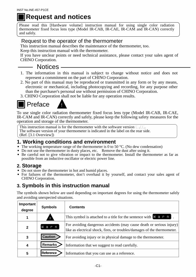
3. Symbols in this instruction manual The symbols shown below are used depending on important degrees for using the thermometer safely and avoiding unexpected situations.
Important degree
Symbols Contents
1 This symbol is attached to a title for the sentence with .
2 For avoiding dangerous accidents (may cause death or serious injury)
like as electrical shock, fires, or troubles/damages of the thermometer.
3 For avoiding injury or in physical damage to the thermometer.
4 Information that we suggest to read carefully.
5 Information that you can use as a reference.
Request and notices
Please read this [Hardware volume] instruction manual for using single color radiation thermometer fixed focus lens type (Model IR-CAB, IR-CAE, IR-CAM and IR-CAN) correctly and safely.
! Preface
This instruction manual is for the thermometer with the software version . . The software version of your thermometer is indicated in the label on the rear side. (Ref. [3.1 Overview])
! Warning
Warning
Caution
Remarks
Reference
INST No.INE-457-P1CE
-C2-
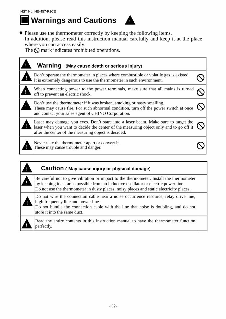
♦Please use the thermometer correctly by keeping the following items. In addition, please read this instruction manual carefully and keep it at the place where you can access easily.
The mark indicates prohibited operations. Warning (May cause death or serious injury) Don’t operate the thermometer in places where combustible or volatile gas is existed.
It is extremely dangerous to use the thermometer in such environment.
When connecting power to the power terminals, make sure that all mains is turned off to prevent an electric shock.
Don’t use the thermometer if it was broken, smoking or nasty smelling. These may cause fire. For such abnormal condition, turn off the power switch at once and contact your sales agent of CHINO Corporation.
Laser may damage you eyes. Don’t stare into a laser beam. Make sure to target the laser when you want to decide the center of the measuring object only and to go off it after the center of the measuring object is decided.
Never take the thermometer apart or convert it. These may cause trouble and danger.
Caution(May cause injury or physical damage)
Be careful not to give vibration or impact to the thermometer. Install the thermometer by keeping it as far as possible from an inductive oscillator or electric power line. Do not use the thermometer in dusty places, noisy places and static electricity places.
Do not wire the connection cable near a noise occurrence resource, relay drive line, high frequency line and power line. Do not bundle the connection cable with the line that noise is doubling, and do not store it into the same duct.
Read the entire contents in this instruction manual to have the thermometer function
perfectly.
! Warnings and Cautions
!
!
!
!
!
!
!
!
!
!
INST No.INE-457-P1CE
-C 3 -
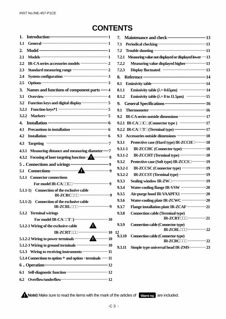
Note) Make sure to read the items with the mark of the articles of are included.
CONTENTS 1. Introduction··································································· 1 1.1 General·································································· 1 2 . Model ··············································································· 1 2.1 Models··································································· 1 2.2 IR-CA series accessories models ··························· 2 2.3 Standard measuring range ··································· 2 2.4 System configuration ············································ 3 2.5 Options·································································· 3
3. Names and functions of component parts ········ 4 3.1 Overview······························································· 4 3.2 Function keys and digital display·························· 5 3.2.1 Function keys*1 ················································· 5 3.2.2 Markers······························································ 5
4. Installation ····································································· 6 4.1 Precautions in installation····································· 6 4.2 Installation ···························································· 6
4.3 Targeting ······························································7
4.3.1 Measuring distance and measuring diameter······7 4.3.2 Focusing of laser targeting function······················· 8
5.Connections and wirings············································ 9 5.1 Connections···························································9 5.1.1 Connector connections
For model IR-CA C ··································· 9 5.1.1-1) Connection of the exclusive cable
IR-ZCRC ······························9 5.1.1-2) Connection of the exclusive cable
IR-ZCRL ·······························9 5.1.2 Terminal wirings
For model IR-CA T )································· 10 5.1.2-1 Wiring of the exclusive cable
IR-ZCRT ····························· 10 12 5.1.2-2 Wiring to power terminals································· 10 5.1.2-3 Wiring to ground terminals ······························· 10 5.1.3 Wiring to receiving instruments ························· 11 5.1.4 Connections to option + and option - terminals ······ 11
6.Operation········································································· 12
6.1 Self-diagnostic function········································· 12
6.2 Overflow/underflow·············································· 12
7. Maintenance and check············································ 13 7.1 Periodical checking················································13 7.2 Trouble shooting····················································13 7.2.1 Measuring value not displayed or displayed lower ····13 7.2.2 Measuring value displayed higher····················13 7.2.3 Display fluctuated ···········································13
8. Reference ········································································ 14 8.1 Emissivity table······················································14 8.1.1 Emissivity table (λ= 0.65µm) ··························14 8.1.2 Emissivity table (λ= 8 to 11.5µm) ···················15
9. General Specifications··············································· 16 9.1 Thermometer ························································16 9.2 IR-CA series outside dimensions ···························17 9.2.1 IR-CA C (Connector type ) ··························17 9.2.2 IR-CA T (Terminal type)···································· 17 9.3 Accessories outside dimensions ·····························18 9.3.1 Protective case (Hard type) IR-ZCCH ···········18 9.3.1-1 IR-ZCCHC (Connector type)························18 9.3.1-2 IR-ZCCHT (Terminal type) ··························18 9.3.2 Protective case (Soft type) IR-ZCCS ··············19 9.3.2-1 IR-ZCCSC (Connector type) ························19 9.3.2-2 IR-ZCCST (Terminal type)···························19 9.3.3 Sealing window IR-ZW ··································19 9.3.4 Water-cooling flange IR-VSW ·························20 9.3.5 Air-purge hood IR-VAAPFX1 ·························20 9.3.6 Water-cooling plate IR-ZCWC ························20 9.3.7 Flange installation plate IR-ZCAF···················21 9.3.8 Connection cable (Terminal type)
IR-ZCRT ··················21 9.3.9 Connection cable (Connector type)
IR-ZCRL ···················22 9.3.10 Connection cable (Connector type)
IR-ZCRC ··················22 9.3.11 Simple type universal head IR-ZMS·················· 23
!
!
!
!
Warni ng !
INST.No.INE-457-P1CE
- 1 -
IEC61326+A1+A2 Emission classA Immunity AnnexA
1.1 General
IR-CAB, IR-CAE, IR-CAM and IR-CAN are single color radiation thermometer. Converting functions enabling digital temperature display and parameter programming are built-in. This thermometer is the high accuracy fixed focus type that adopted the front chop method. And this thermometer has laser targeting function for targeting to the measuring objects. A low temperature/long wavelength type IR-CAB is suited to measure the low temperature area to high accuracy. A low temperature/short wavelength type IR-CAE is suited to measure the low temperature area to high speed. Also it is suited to measurement such as metal, by short measuring wavelength. IR-CAM for polyethylene film and IR-CAN for polyester film are able to measure film temperature well accuracy, with the thermometer that used the absorption wavelength of each film. The radiation energy collected through the objective lens is transmitted to the element is converted into an electrical signal. The element output is digitally converted and processed through emissivity compensation, linealizer and modulation. The standardized final output is 4 to 20mA DC. Functional keys make programming or selection of emissivity, signal modulation and alarm function easy. 2 types of connection by terminals or a connector are available in this thermometer depending on a connection cable. Various options and accessories are prepared for every kind of applications.
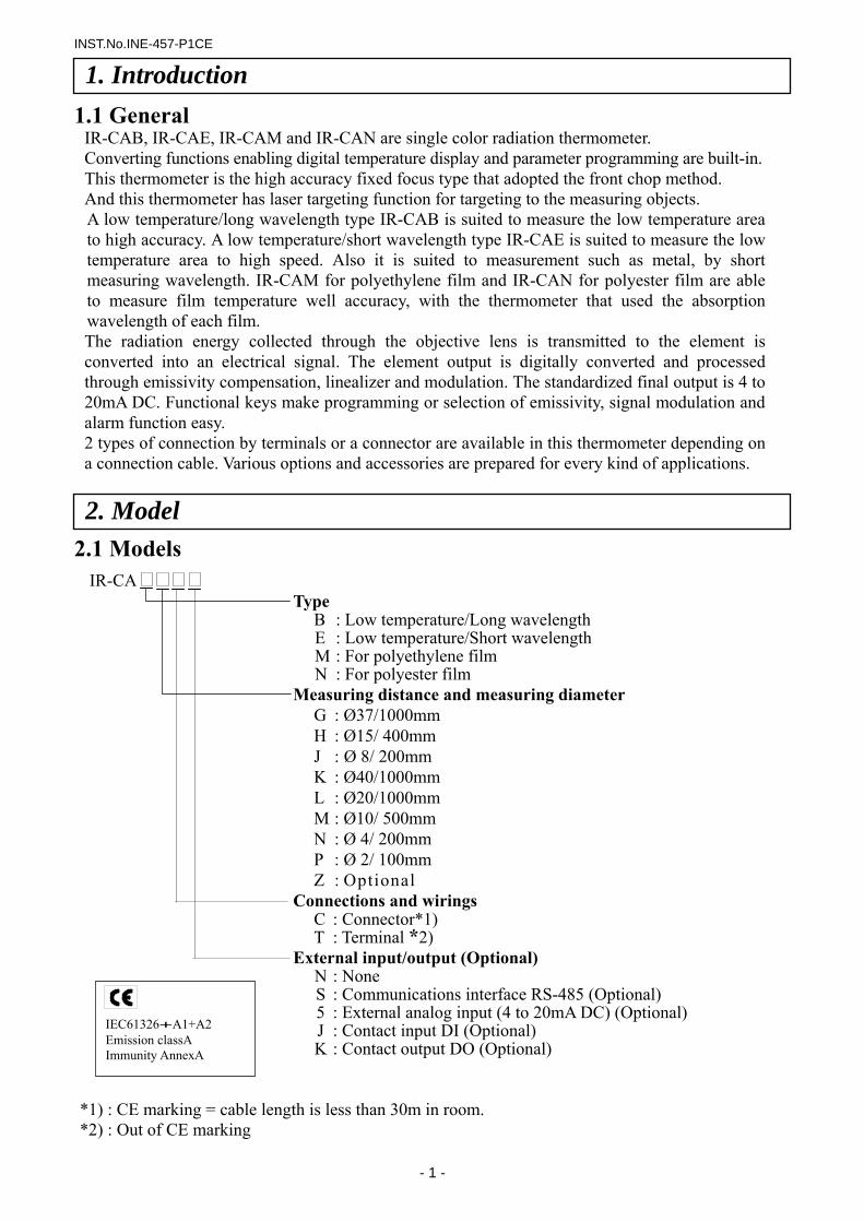
2.1 Models
IR-CA Type
B : Low temperature/Long wavelength E : Low temperature/Short wavelength M : For polyethylene film N : For polyester film
Measuring distance and measuring diameter G : Ø37/1000mm H : Ø15/ 400mm J : Ø 8/ 200mm K : Ø40/1000mm L : Ø20/1000mm M : Ø10/ 500mm N : Ø 4/ 200mm P : Ø 2/ 100mm Z : Optional
Connections and wirings C : Connector*1) T : Terminal *2)
External input/output (Optional) N : None S : Communications interface RS-485 (Optional) 5 : External analog input (4 to 20mA DC) (Optional) J : Contact input DI (Optional) K : Contact output DO (Optional)
1. Introduction
2. Model
*1) : CE marking = cable length is less than 30m in room. *2) : Out of CE marking
INST.No.INE-457-P1CE
- 2 -
2.2 IR-CA series accessories models
Accessories Model Remarks Protective case(Hard type) IR-ZCCH C: Connector type T: Terminal type Protective case(Soft type) IR-ZCCS C: Connector type T: Terminal type Sealing window IR-ZW 0: Quartz glass 1:CaF2 2:BaF2 Water-cooling flange IR-VSW Air-purge hood IR-VAAPFX1 Water-cooling plate IR-ZCWC Flange installation plate IR-ZCAF Connection cable (Connector type) IR-ZCRC : Length is as designated (m), Max200mConnection cable (Connector IR-ZCRL : Length is as designated (m), Max50m Connection cable (Terminal type) IR-ZCRT : Length is as designated (m), Max200mSimple type universal head IR-ZMS
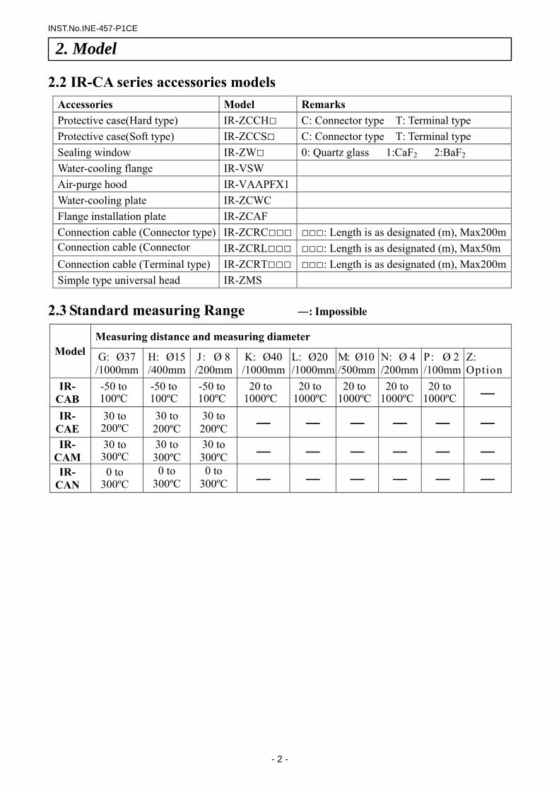
2.3 Standard measuring Range ―: Impossible
Measuring distance and measuring diameter
Model G: Ø37 /1000mm
H: Ø15 /400mm
J: Ø 8 /200mm
K: Ø40/1000mm
L: Ø20/1000mm
M: Ø10/500mm
N: Ø 4 /200mm
P: Ø 2 /100mm
Z: Option
IR- CAB
-50 to 100ºC
-50 to 100ºC
-50 to 100ºC
20 to 1000ºC
20 to 1000ºC
20 to 1000ºC
20 to 1000ºC
20 to 1000ºC ―
IR- CAE
30 to 200ºC
30 to 200ºC
30 to 200ºC ― ― ― ― ― ―
IR- CAM
30 to 300ºC
30 to 300ºC
30 to 300ºC ― ― ― ― ― ―
IR- CAN
0 to 300ºC
0 to 300ºC
0 to 300ºC ― ― ― ― ― ―
2. Model
INST.No.INE-457-P1CE
- 3 -
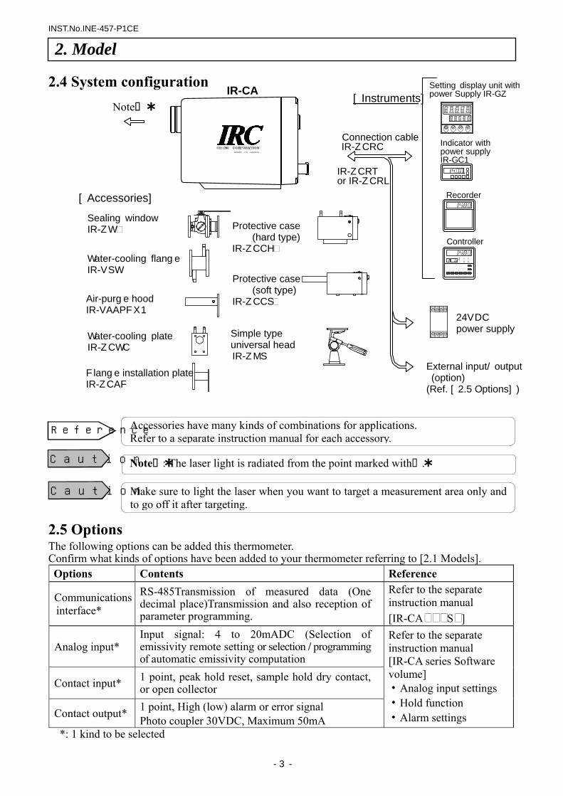
Accessories have many kinds of combinations for applications. Refer to a separate instruction manual for each accessory.
Note : The laser light is radiated from the point marked with .
Make sure to light the laser when you want to target a measurement area only and to go off it after targeting.
2.4 System configuration
2.5 Options The following options can be added this thermometer. Confirm what kinds of options have been added to your thermometer referring to [2.1 Models]. Options Contents Reference
Communications interface*
RS-485Transmission of measured data (One decimal place)Transmission and also reception of parameter programming.
Refer to the separate instruction manual [IR-CA S ]
Analog input* Input signal: 4 to 20mADC (Selection of emissivity remote setting or selection / programming of automatic emissivity computation
Contact input* 1 point, peak hold reset, sample hold dry contact, or open collector
Contact output* 1 point, High (low) alarm or error signal Photo coupler 30VDC, Maximum 50mA
Refer to the separate instruction manual [IR-CA series Software volume] ・Analog input settings ・Hold function ・Alarm settings
*: 1 kind to be selected
[Accessories]
Note
External input/output (option) (Ref. [2.5 Options])
Caution
Caution
2. Model
24VDC power supply
Controller
Recorder
Indicator with power supply IR-GC1
IR-CA
Reference
Sealing window IR-ZW
Water-cooling flange IR-VSW
Air-purge hood IR-VAAPFX1
Water-cooling plate IR-ZCWC
Flange installation plate IR-ZCAF
Protective case (hard type)
IR-ZCCH
Protective case (soft type)
IR-ZCCS
Simple type universal head IR-ZMS
Setting display unit with power Supply IR-GZ
Connection cable IR-ZCRC
[Instruments]
IR-ZCRTor IR-ZCRL
INST.No.INE-457-P1CE
- 4 -
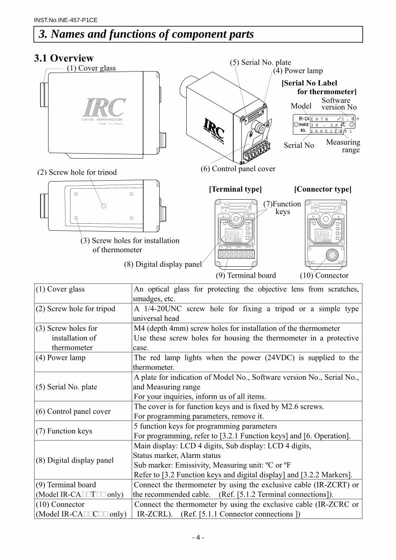
3.1 Overview
(1) Cover glass An optical glass for protecting the objective lens from scratches, smudges, etc.
(2) Screw hole for tripod A 1/4-20UNC screw hole for fixing a tripod or a simple type universal head
(3) Screw holes for installation of thermometer
M4 (depth 4mm) screw holes for installation of the thermometer Use these screw holes for housing the thermometer in a protective case.
(4) Power lamp The red lamp lights when the power (24VDC) is supplied to the thermometer.
(5) Serial No. plate A plate for indication of Model No., Software version No., Serial No., and Measuring range For your inquiries, inform us of all items.
(6) Control panel cover The cover is for function keys and is fixed by M2.6 screws. For programming parameters, remove it.
(7) Function keys 5 function keys for programming parameters For programming, refer to [3.2.1 Function keys] and [6. Operation].
(8) Digital display panel
Main display: LCD 4 digits, Sub display: LCD 4 digits, Status marker, Alarm status Sub marker: Emissivity, Measuring unit: ºC or ºF Refer to [3.2 Function keys and digital display] and [3.2.2 Markers].
(9) Terminal board (Model IR-CA T only)
Connect the thermometer by using the exclusive cable (IR-ZCRT) or the recommended cable. (Ref. [5.1.2 Terminal connections]).
(10) Connector (Model IR-CA C only)
Connect the thermometer by using the exclusive cable (IR-ZCRC or IR-ZCRL). (Ref. [5.1.1 Connector connections ])
/1.00EHTN
30 - 200
IA051E001
3. Names and functions of component parts
(2) Screw hole for tripod
[Serial No Labelfor thermometer]
Model Software version No
Serial No Measuring range
[Terminal type] [Connector type]
(7)Function keys
(9) Terminal board (10) Connector
(6) Control panel cover
(1) Cover glass (4) Power lamp (5) Serial No. plate
(3) Screw holes for installationof thermometer
(8) Digital display panel
INST.No.INE-457-P1CE
- 5 -
Sub display*3
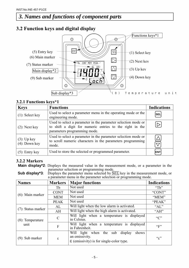
3.2 Function keys and digital display
3.2.1 Functions keys*1 Keys Functions Indications
(1): Select key Used to select a parameter menu in the operating mode or the engineering mode.
(2): Next key Used to select a parameter in the parameter selection mode or to shift a digit for numeric entries to the right in the parameters programming mode.
(3): Up key (4): Down key
Used to select a parameter in the parameter selection mode or to scroll numeric characters in the parameters programming mode.
(5): Entry key Used to store the selected or programmed parameter.
3.2.2 Markers Main display*2: Displays the measured value in the measurement mode, or a parameter in the
parameter selection or programming mode. Sub display*3: Displays the parameter menu selected by SEL key in the measurement mode, or
a parameter menu in the parameter selection or programming mode. Names Markers Major functions Indications
Tb Not used “Tb” CONT Not used “CONT” MEM Not used “MEM” (6): Main marker
PEAK Not used “PEAK” AL Will light when the low alarm is activated. “AL” (7): Status marker AH Will light when the high alarm is activated. “AH”
C Will light when a temperature is displayed in Celsius. “C” (8): Temperature
unit F Will light when a temperature is displayed in Fahrenheit. “F”
(9): Sub marker ε Will light when the sub display shows an emissivity. ε (emissivity) is for single-color type.
“ε”
SEL
ENT
3. Names and functions of component parts
(1) Select key
(2) Next key
(3) Up key
(4) Down key
(5) Entry key (6) Main marker
(7) Status marker
(8) Temperature unit
(9) Sub marker
Functions keys*1
Main display*2
INST.No.INE-457-P1CE
- 6 -
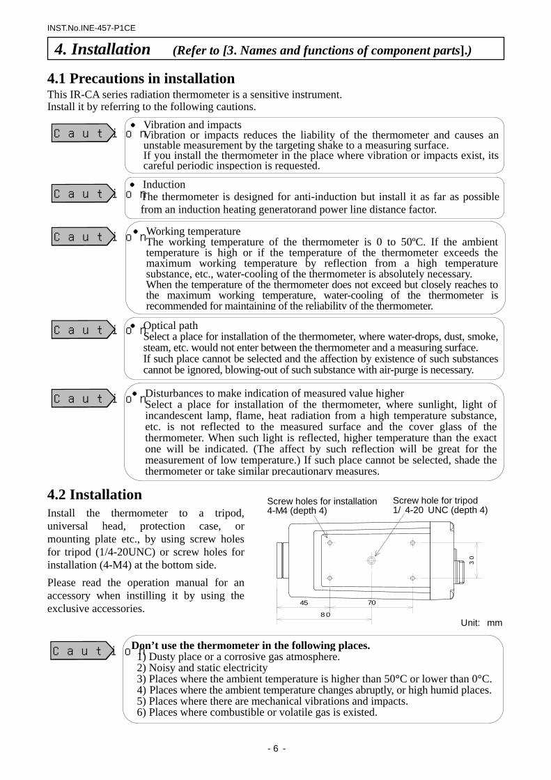
4.1 Precautions in installation This IR-CA series radiation thermometer is a sensitive instrument. Install it by referring to the following cautions.
4.2 Installation Install the thermometer to a tripod, universal head, protection case, or mounting plate etc., by using screw holes for tripod (1/4-20UNC) or screw holes for installation (4-M4) at the bottom side. Please read the operation manual for an accessory when instilling it by using the exclusive accessories.
4. Installation (Refer to [3. Names and functions of component parts].)
Vibration and impactsVibration or impacts reduces the liability of the thermometer and causes an unstable measurement by the targeting shake to a measuring surface. If you install the thermometer in the place where vibration or impacts exist, its careful periodic inspection is requested.
Caution
Induction The thermometer is designed for anti-induction but install it as far as possible from an induction heating generatorand power line distance factor.
Caution
Working temperatureThe working temperature of the thermometer is 0 to 50ºC. If the ambienttemperature is high or if the temperature of the thermometer exceeds the maximum working temperature by reflection from a high temperature substance, etc., water-cooling of the thermometer is absolutely necessary. When the temperature of the thermometer does not exceed but closely reaches tothe maximum working temperature, water-cooling of the thermometer is recommended for maintaining of the reliability of the thermometer.
Caution
Optical path Select a place for installation of the thermometer, where water-drops, dust, smoke, steam, etc. would not enter between the thermometer and a measuring surface. If such place cannot be selected and the affection by existence of such substances cannot be ignored, blowing-out of such substance with air-purge is necessary.
Caution
Disturbances to make indication of measured value higher Select a place for installation of the thermometer, where sunlight, light of incandescent lamp, flame, heat radiation from a high temperature substance,etc. is not reflected to the measured surface and the cover glass of the thermometer. When such light is reflected, higher temperature than the exact one will be indicated. (The affect by such reflection will be great for the measurement of low temperature.) If such place cannot be selected, shade the thermometer or take similar precautionary measures.
Caution
Don’t use the thermometer in the following places.1) Dusty place or a corrosive gas atmosphere. 2) Noisy and static electricity
3) Places where the ambient temperature is higher than 50°C or lower than 0°C.4) Places where the ambient temperature changes abruptly, or high humid places.5) Places where there are mechanical vibrations and impacts. 6) Places where combustible or volatile gas is existed.
Caution
Screw holes for installation4-M4 (depth 4)
Screw hole for tripod 1/4-20 UNC (depth 4)
45 70
80
30
Unit: mm
INST.No.INE-457-P1CE
- 7 -
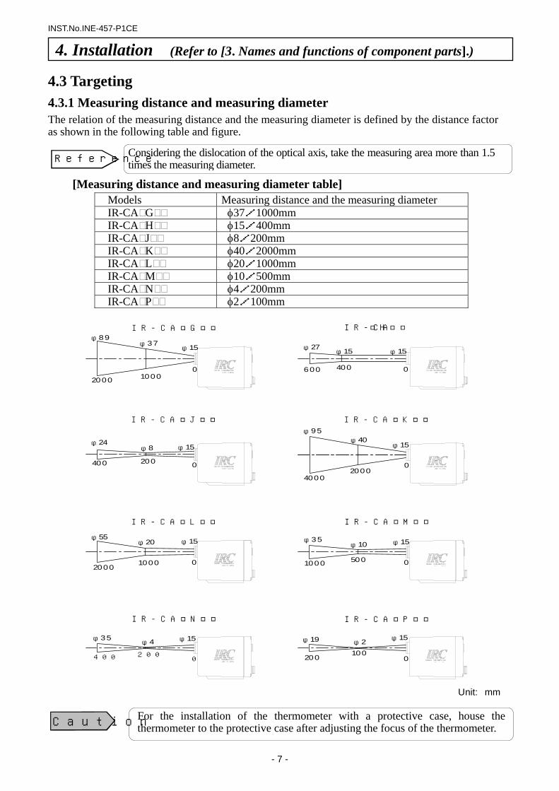
4.3 Targeting 4.3.1 Measuring distance and measuring diameter The relation of the measuring distance and the measuring diameter is defined by the distance factor as shown in the following table and figure.
[Measuring distance and measuring diameter table]
Models Measuring distance and the measuring diameter IR-CA G φ37/1000mm IR-CA H φ15/400mm IR-CA J φ8/200mm IR-CA K φ40/2000mm IR-CA L φ20/1000mm IR-CA M φ10/500mm IR-CA N φ4/200mm IR-CA P φ2/100mm
4. Installation (Refer to [3. Names and functions of component parts].)
Considering the dislocation of the optical axis, take the measuring area more than 1.5 times the measuring diameter.Reference
For the installation of the thermometer with a protective case, house the thermometer to the protective case after adjusting the focus of the thermometer. Caution
Unit: mm
IR-CAGφ89
φ37φ15
100020000
IR-CAH
φ27φ15
600 400 0
φ15
IR-CAJ
φ24φ8 φ15
200400 0
IR-CAK
φ40φ15
φ95
20004000
0
φ15φ20φ55
20001000 0
IR-CAL IR-CAM
φ15φ35φ10
1000 500 0
IR-CAN
φ15φ4
200400 0
φ35
IR-CAP
φ15φ19 φ2
200 1000
INST.No.INE-457-P1CE
- 8 -
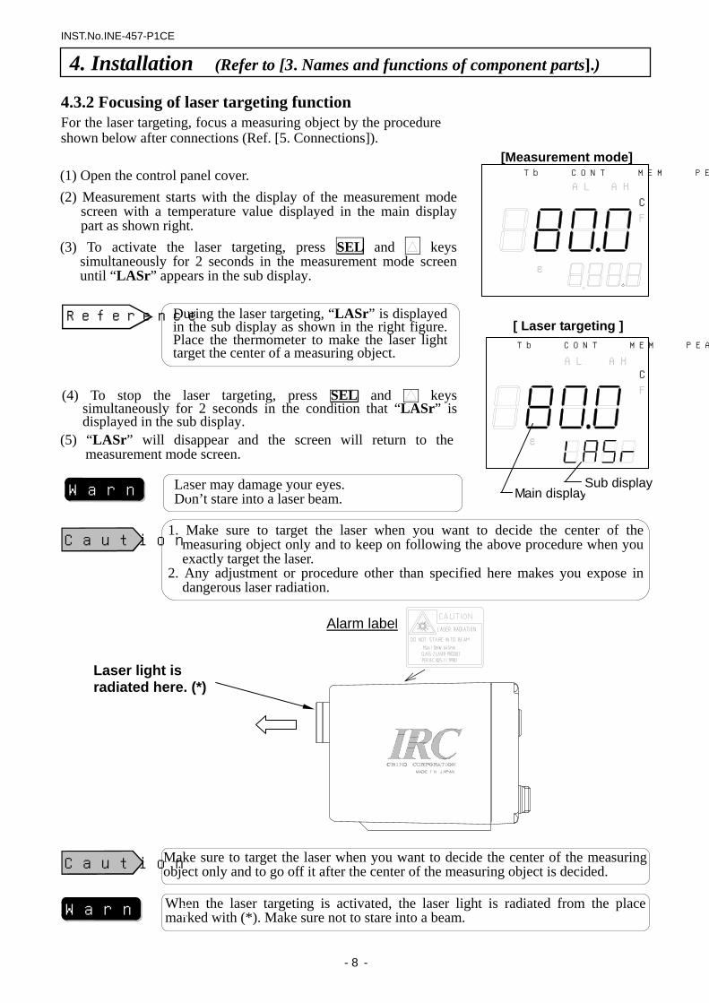
(1) Open the control panel cover. (2) Measurement starts with the display of the measurement mode
screen with a temperature value displayed in the main display part as shown right.
(3) To activate the laser targeting, press SEL and keys simultaneously for 2 seconds in the measurement mode screen until “LASr” appears in the sub display.
(4) To stop the laser targeting, press SEL and keys simultaneously for 2 seconds in the condition that “LASr” is displayed in the sub display.
(5) “LASr” will disappear and the screen will return to the measurement mode screen.
4.3.2 Focusing of laser targeting function For the laser targeting, focus a measuring object by the procedure shown below after connections (Ref. [5. Connections]).
4. Installation (Refer to [3. Names and functions of component parts].)
Tb CONT MEM PEAK
AL AH
C
F
ε
[Measurement mode]
During the laser targeting, “LASr” is displayed in the sub display as shown in the right figure. Place the thermometer to make the laser light target the center of a measuring object.
Reference
Tb CONT MEM PEAK
AL AHC
F
ε
[ Laser targeting ]
Main displaySub displayLaser may damage your eyes.
Don’t stare into a laser beam. Warning
1. Make sure to target the laser when you want to decide the center of the measuring object only and to keep on following the above procedure when you exactly target the laser.
2. Any adjustment or procedure other than specified here makes you expose in dangerous laser radiation.
Caution
Laser light is radiated here. (*)
Alarm label
Make sure to target the laser when you want to decide the center of the measuring object only and to go off it after the center of the measuring object is decided. Caution
When the laser targeting is activated, the laser light is radiated from the place marked with (*). Make sure not to stare into a beam. Warning
INST.No.INE-457-P1CE
- 9 -
24V DC power supply
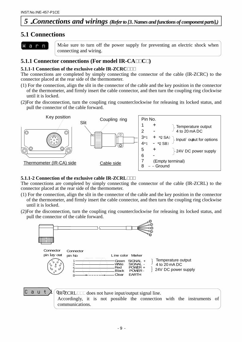
IR-ZCRL does not have input/output signal line. Accordingly, it is not possible the connection with the instruments of communications.
5.1 Connections
5.1.1 Connector connections (For model IR-CA C ) 5.1.1-1 Connection of the exclusive cable IR-ZCRC The connections are completed by simply connecting the connector of the cable (IR-ZCRC) to the connector placed at the rear side of the thermometer. (1) For the connection, align the slit in the connector of the cable and the key position in the connector
of the thermometer, and firmly insert the cable connector, and then turn the coupling ring clockwise until it is locked.
(2)For the disconnection, turn the coupling ring counterclockwise for releasing its locked status, and pull the connector of the cable forward.
5.1.1-2 Connection of the exclusive cable IR-ZCRL The connections are completed by simply connecting the connector of the cable (IR-ZCRL) to the connector placed at the rear side of the thermometer. (1) For the connection, align the slit in the connector of the cable and the key position in the connector
of the thermometer, and firmly insert the cable connector, and then turn the coupling ring clockwise until it is locked.
(2)For the disconnection, turn the coupling ring counterclockwise for releasing its locked status, and pull the connector of the cable forward.
5.Connections and wirings (Refer to [3. Names and functions of component parts].)
Make sure to turn off the power supply for preventing an electric shock when connecting and wiring.
Warning
Key position Coupling ring
Thermometer (IR-CA) side Cable side
Slit Pin No. 1 +
2 - 3*1 + (*2 SA)
4*1 - (*2 SB)
5 +
6 - 7 8 ―― Ground
Temperature output 4 to 20mA DC
Input/output for options
24V DC power supply
(Empty terminal)
12568
Connectorpin lay out Line color Marker
Green SIGNAL +White SIGNAL -Red POWER +Black POWER-Clear EARTH
Connectorpin No
Temperature output 4 to 20mA DC
Caution
INST.No.INE-457-P1CE
- 10 -
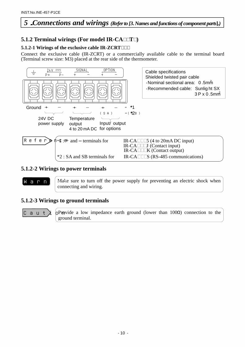
5.1.2 Terminal wirings (For model IR-CA T ) 5.1.2-1 Wirings of the exclusive cable IR-ZCRT Connect the exclusive cable (IR-ZCRT) or a commercially available cable to the terminal board (Terminal screw size: M3) placed at the rear side of the thermometer. 5.1.2-2 Wirings to power terminals 5.1.2-3 Wirings to ground terminals
Ground + -
Temperature output 4 to 20mA DC
+ -
24V DC power supply
+ -
Input/output for options
(SA) (SB)
→ *1
→ *2
Cable specifications Shielded twisted pair cable ・Nominal sectional area: 0.5mm2
・Recommended cable: Sunlight SX 3P x 0.5mm2
*1 : + and – terminals for IR-CA 5 (4 to 20mA DC input) IR-CA J (Contact input) IR-CA K (Contact output) *2 : SA and SB terminals for IR-CA S (RS-485 communications)
Reference
Make sure to turn off the power supply for preventing an electric shock when connecting and wiring.
Warning
Provide a low impedance earth ground (lower than 100Ω) connection to the ground terminal.
Caution
5.Connections and wirings (Refer to [3. Names and functions of component parts].)
INST.No.INE-457-P1CE
- 11 -
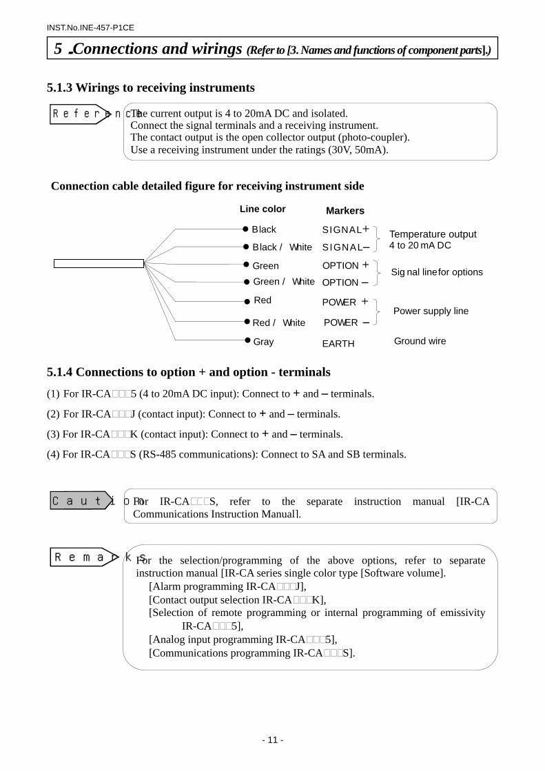
5.1.3 Wirings to receiving instruments 5.1.4 Connections to option + and option - terminals
(1) For IR-CA 5 (4 to 20mA DC input): Connect to + and – terminals.
(2) For IR-CA J (contact input): Connect to + and – terminals.
(3) For IR-CA K (contact input): Connect to + and – terminals.
(4) For IR-CA S (RS-485 communications): Connect to SA and SB terminals.
For IR-CA S, refer to the separate instruction manual [IR-CA Communications Instruction Manual].
For the selection/programming of the above options, refer to separate instruction manual [IR-CA series single color type [Software volume].
[Alarm programming IR-CA J], [Contact output selection IR-CA K], [Selection of remote programming or internal programming of emissivity
IR-CA 5], [Analog input programming IR-CA 5], [Communications programming IR-CA S].
Caution
Remarks
5.Connections and wirings (Refer to [3. Names and functions of component parts].)
The current output is 4 to 20mA DC and isolated.Connect the signal terminals and a receiving instrument. The contact output is the open collector output (photo-coupler). Use a receiving instrument under the ratings (30V, 50mA).
Reference
Black SIGNAL+SIGNAL–OPTION +OPTION –POWER +POWER –
Gray EARTH
Temperature output4 to 20mA DC
Signal line for options
Power supply line
Ground wire
Markers Line color
Connection cable detailed figure for receiving instrument side
Black / White
GreenGreen / White
Red
Red / White
INST.No.INE-457-P1CE
-12-
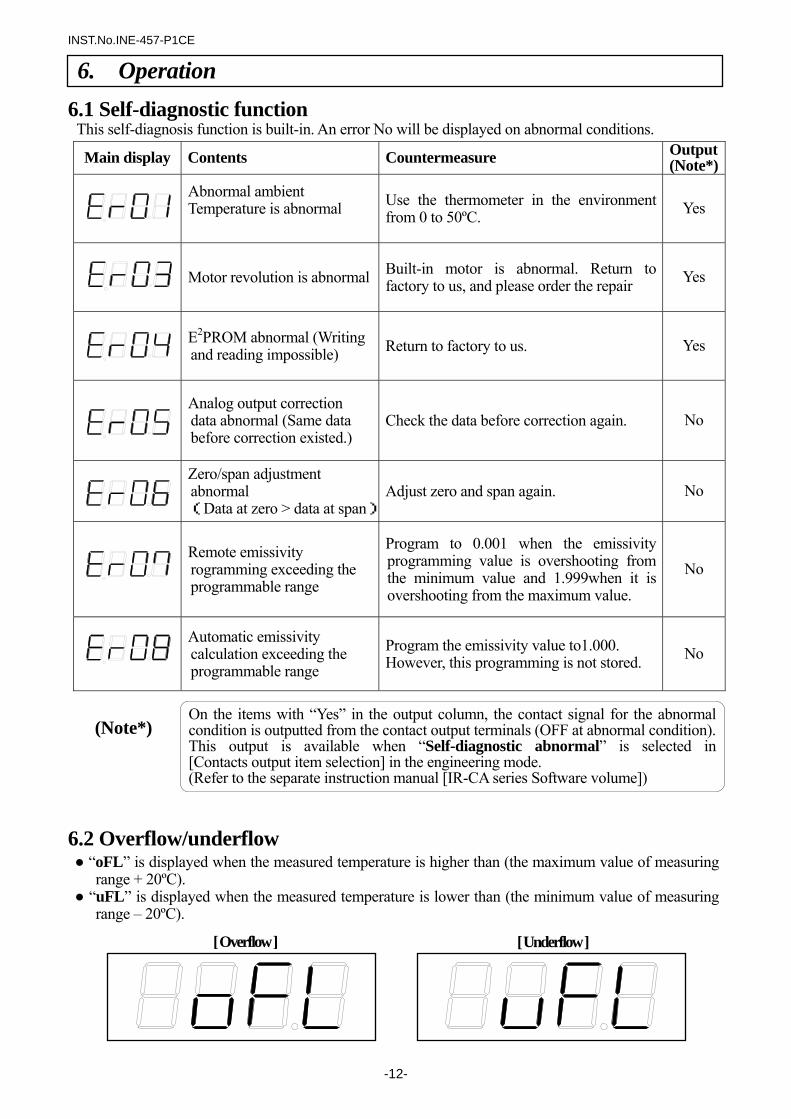
6.1 Self-diagnostic function
This self-diagnosis function is built-in. An error No will be displayed on abnormal conditions.
Main display Contents Countermeasure Output (Note*)
Abnormal ambient Temperature is abnormal
Use the thermometer in the environment from 0 to 50ºC. Yes
Motor revolution is abnormal Built-in motor is abnormal. Return to factory to us, and please order the repair Yes
E2PROM abnormal (Writing and reading impossible) Return to factory to us. Yes
Analog output correction data abnormal (Same data before correction existed.)
Check the data before correction again. No
Zero/span adjustment abnormal (Data at zero > data at span)
Adjust zero and span again. No
Remote emissivity
rogramming exceeding the programmable range
Program to 0.001 when the emissivity programming value is overshooting from the minimum value and 1.999when it is overshooting from the maximum value.
No
Automatic emissivity calculation exceeding the programmable range
Program the emissivity value to1.000. However, this programming is not stored. No
(Note*)
6.2 Overflow/underflow “oFL” is displayed when the measured temperature is higher than (the maximum value of measuring
range + 20ºC). “uFL” is displayed when the measured temperature is lower than (the minimum value of measuring
range – 20ºC).
On the items with “Yes” in the output column, the contact signal for the abnormal condition is outputted from the contact output terminals (OFF at abnormal condition).This output is available when “Self-diagnostic abnormal” is selected in [Contacts output item selection] in the engineering mode. (Refer to the separate instruction manual [IR-CA series Software volume])
[ Overflow ] [ Underflow ]
6. Operation
INST.No.INE-457-P1CE
-13-
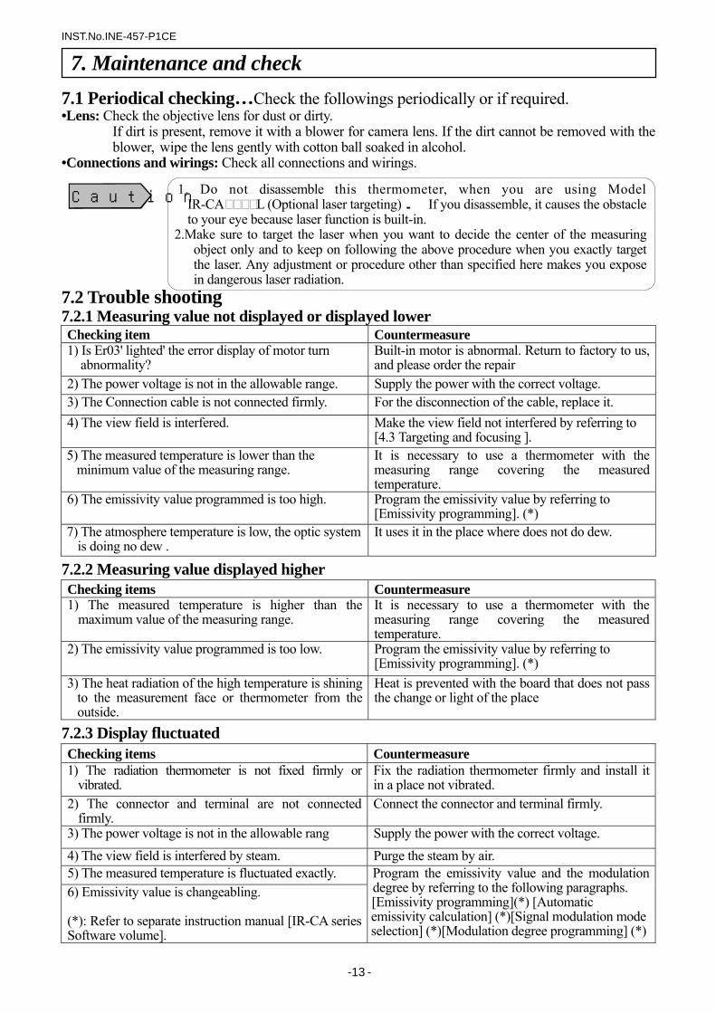
7.1 Periodical checking…Check the followings periodically or if required. •Lens: Check the objective lens for dust or dirty.
If dirt is present, remove it with a blower for camera lens. If the dirt cannot be removed with the blower, wipe the lens gently with cotton ball soaked in alcohol.
•Connections and wirings: Check all connections and wirings.
7.2 Trouble shooting 7.2.1 Measuring value not displayed or displayed lower Checking item Countermeasure 1) Is Er03' lighted' the error display of motor turn
abnormality? Built-in motor is abnormal. Return to factory to us, and please order the repair
2) The power voltage is not in the allowable range. Supply the power with the correct voltage. 3) The Connection cable is not connected firmly. For the disconnection of the cable, replace it. 4) The view field is interfered. Make the view field not interfered by referring to
[4.3 Targeting and focusing ]. 5) The measured temperature is lower than the
minimum value of the measuring range. It is necessary to use a thermometer with the measuring range covering the measured temperature.
6) The emissivity value programmed is too high. Program the emissivity value by referring to [Emissivity programming]. (*)
7) The atmosphere temperature is low, the optic system is doing no dew .
It uses it in the place where does not do dew.
7.2.2 Measuring value displayed higher Checking items Countermeasure 1) The measured temperature is higher than the
maximum value of the measuring range. It is necessary to use a thermometer with the measuring range covering the measured temperature.
2) The emissivity value programmed is too low. Program the emissivity value by referring to [Emissivity programming]. (*)
3) The heat radiation of the high temperature is shining to the measurement face or thermometer from the outside.
Heat is prevented with the board that does not pass the change or light of the place
7.2.3 Display fluctuated Checking items Countermeasure 1) The radiation thermometer is not fixed firmly or
vibrated. Fix the radiation thermometer firmly and install it in a place not vibrated.
2) The connector and terminal are not connected firmly.
Connect the connector and terminal firmly.
3) The power voltage is not in the allowable rang Supply the power with the correct voltage. 4) The view field is interfered by steam. Purge the steam by air. 5) The measured temperature is fluctuated exactly. 6) Emissivity value is changeabling. (*): Refer to separate instruction manual [IR-CA series Software volume].
Program the emissivity value and the modulation degree by referring to the following paragraphs. [Emissivity programming](*) [Automatic emissivity calculation] (*)[Signal modulation mode selection] (*)[Modulation degree programming] (*)
7. Maintenance and check
1. Do not disassemble this thermometer, when you are using Model IR-CA L (Optional laser targeting). If you disassemble, it causes the obstacle to your eye because laser function is built-in.
2.Make sure to target the laser when you want to decide the center of the measuring object only and to keep on following the above procedure when you exactly target the laser. Any adjustment or procedure other than specified here makes you expose in dangerous laser radiation.
Caution
INST.No.INE-457-P1CE
-14-
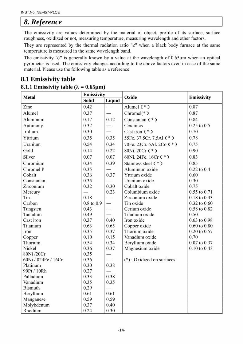
The emissivity are values determined by the material of object, profile of its surface, surface roughness, oxidized or not, measuring temperature, measuring wavelength and other factors. They are represented by the thermal radiation ratio "ε" when a black body furnace at the same temperature is measured in the same wavelength band. The emissivity "ε" is generally known by a value at the wavelength of 0.65µm when an optical pyrometer is used. The emissivity changes according to the above factors even in case of the same material. Please use the following table as a reference.
8.1 Emissivity table 8.1.1 Emissivity table (λ = 0.65µm)
Emissivity Metal Solid Liquid Oxide Emissivity
Zinc 0.42 ― Alumel(*) 0.87 Alumel 0.37 ― Chromel(*) 0.87 Aluminum 0.17 0.12 Constantan(*) 0.84 Antimony 0.32 ― Ceramics 0.25 to 0.5 Iridium 0.30 ― Cast iron(*) 0.70 Yttrium 0.35 0.35 55Fe. 37.5Cr. 7.5Al(*) 0.78 Uranium 0.54 0.34 70Fe. 23Cr. 5Al. 2Co(*) 0.75 Gold 0.14 0.22 80Ni. 20Cr(*) 0.90 Silver 0.07 0.07 60Ni. 24Fe. 16Cr(*) 0.83 Chromium 0.34 0.39 Stainless steel(*) 0.85 Chromel P 0.35 ― Aluminum oxide 0.22 to 0.4 Cobalt 0.36 0.37 Yttrium oxide 0.60 Constantan 0.35 ― Uranium oxide 0.30 Zirconium 0.32 0.30 Cobalt oxide 0.75 Mercury ― 0.23 Columbium oxide 0.55 to 0.71 Tin 0.18 ― Zirconium oxide 0.18 to 0.43 Carbon 0.8 to 0.9 ― Tin oxide 0.32 to 0.60 Tungsten 0.43 ― Cerium oxide 0.58 to 0.82 Tantalum 0.49 ― Titanium oxide 0.50 Cast iron 0.37 0.40 Iron oxide 0.63 to 0.98 Titanium 0.63 0.65 Copper oxide 0.60 to 0.80 Iron 0.35 0.37 Thorium oxide 0.20 to 0.57 Copper 0.10 0.15 Vanadium oxide 0.70 Thorium 0.54 0.34 Beryllium oxide 0.07 to 0.37 Nickel 0.36 0.37 Magnesium oxide 0.10 to 0.43 80Ni /20Cr 0.35 ― 60Ni / 024Fe / 16Cr 0.36 ― (*) : Oxidized on surfaces Platinum 0.30 0.38 90Pt / 10Rh 0.27 ― Palladium 0.33 0.38 Vanadium 0.35 0.35 Bismuth 0.29 ― Beryllium 0.61 0.61 Manganese 0.59 0.59 Molybdenum 0.37 0.40 Rhodium 0.24 0.30
8. Reference
INST.No.INE-457-P1CE
-15-
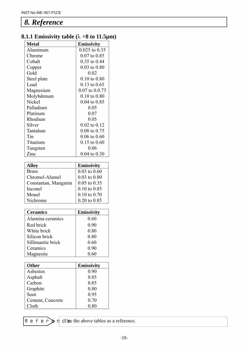
8.1.1 Emissivity table (λ =8 to 11.5µm)
Metal Emissivity Aluminum 0.025 to 0.35Chrome 0.07 to 0.85 Cobalt 0.35 to 0.44 Copper 0.03 to 0.80 Gold 0.02 Steel plate 0.10 to 0.80 Lead 0.13 to 0.65 Magnesium 0.07 to 0.0.75Molybdenum 0.10 to 0.80 Nickel 0.04 to 0.85 Palladium 0.05 Platinum 0.07 Rhodium 0.05 Silver 0.02 to 0.12 Tantalum 0.08 to 0.75 Tin 0.06 to 0.60 Titanium 0.15 to 0.60 Tungsten 0.06 Zinc 0.04 to 0.30
Alloy Emissivity Brass 0.03 to 0.60 Chromel-Alumel 0.03 to 0.80 Constantan, Manganin 0.05 to 0.35 Inconel 0.10 to 0.85 Monel 0.10 to 0.70 Nichrome 0.20 to 0.85
Ceramics Emissivity Alumina ceramics 0.60 Red brick 0.90 White brick 0.80 Silicon brick 0.80 Sillimanite brick 0.60 Ceramics 0.90 Magnesite 0.60
Other Emissivity Asbestos 0.90 Asphalt 0.85 Carbon 0.85 Graphite 0.80 Soot 0.95 Cement, Concrete 0.70 Cloth 0.80
8. Reference
Use the above tables as a reference. Reference
INST.No.INE-457-P1CE
-16-
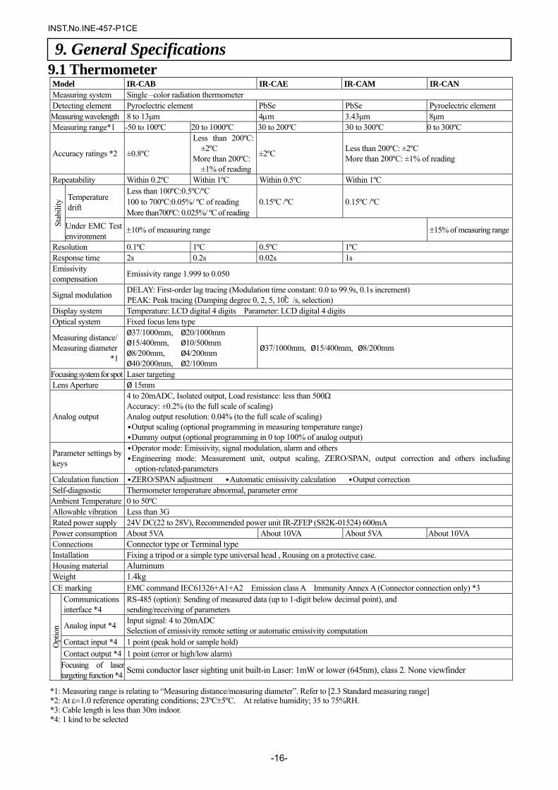
9.1 Thermometer Model IR-CAB IR-CAE IR-CAM IR-CAN Measuring system Single –color radiation thermometer Detecting element Pyroelectric element PbSe PbSe Pyroelectric element Measuring wavelength 8 to 13µm 4µm 3.43µm 8µm Measuring range*1 -50 to 100ºC 20 to 1000ºC 30 to 200ºC 30 to 300ºC 0 to 300ºC
Accuracy ratings *2 ±0.8ºC
Less than 200ºC: ±2ºC
More than 200ºC: ±1% of reading
±2ºC Less than 200ºC: ±2ºC More than 200ºC: ±1% of reading
Repeatability Within 0.2ºC Within 1ºC Within 0.5ºC Within 1ºC
Temperature drift
Less than 100ºC:0.5ºC/ºC 100 to 700ºC:0.05%/ ºC of reading More than700ºC: 0.025%/ ºC of reading
0.15ºC /ºC 0.15ºC /ºC
Stab
ility
Under EMC Test environment
±10% of measuring range ±15% of measuring range
Resolution 0.1ºC 1ºC 0.5ºC 1ºC Response time 2s 0.2s 0.02s 1s Emissivity compensation Emissivity range 1.999 to 0.050
Signal modulation DELAY: First-order lag tracing (Modulation time constant: 0.0 to 99.9s, 0.1s increment) PEAK: Peak tracing (Damping degree 0, 2, 5, 10/s, selection)
Display system Temperature: LCD digital 4 digits Parameter: LCD digital 4 digits Optical system Fixed focus lens type
Measuring distance/ Measuring diameter
*1
Ø37/1000mm, Ø20/1000mm Ø15/400mm, Ø10/500mm Ø8/200mm, Ø4/200mm Ø40/2000mm, Ø2/100mm
Ø37/1000mm, Ø15/400mm, Ø8/200mm
Focusing system for spot Laser targeting Lens Aperture Ø 15mm
Analog output
4 to 20mADC, Isolated output, Load resistance: less than 500Ω Accuracy: ±0.2% (to the full scale of scaling) Analog output resolution: 0.04% (to the full scale of scaling) ∙Output scaling (optional programming in measuring temperature range) ∙Dummy output (optional programming in 0 top 100% of analog output)
Parameter settings by keys
∙Operator mode: Emissivity, signal modulation, alarm and others ∙Engineering mode: Measurement unit, output scaling, ZERO/SPAN, output correction and others including
option-related-parameters Calculation function ∙ZERO/SPAN adjustment ∙Automatic emissivity calculation ∙Output correction Self-diagnostic Thermometer temperature abnormal, parameter error Ambient Temperature 0 to 50ºC Allowable vibration Less than 3G Rated power supply 24V DC(22 to 28V), Recommended power unit IR-ZFEP (S82K-01524) 600mA Power consumption About 5VA About 10VA About 5VA About 10VA Connections Connector type or Terminal type Installation Fixing a tripod or a simple type universal head , Rousing on a protective case. Housing material Aluminum Weight 1.4kg CE marking EMC command IEC61326+A1+A2 Emission class A Immunity Annex A (Connector connection only) *3
Communications interface *4
RS-485 (option): Sending of measured data (up to 1-digit below decimal point), and sending/receiving of parameters
Analog input *4 Input signal: 4 to 20mADC Selection of emissivity remote setting or automatic emissivity computation
Contact input *4 1 point (peak hold or sample hold) Contact output *4 1 point (error or high/low alarm)
Opt
ion
Focusing of laser targeting function *4 Semi conductor laser sighting unit built-in Laser: 1mW or lower (645nm), class 2. None viewfinder
9. General Specifications
*1: Measuring range is relating to “Measuring distance/measuring diameter”. Refer to [2.3 Standard measuring range] *2: At ε=1.0 reference operating conditions; 23ºC±5ºC. At relative humidity; 35 to 75%RH. *3: Cable length is less than 30m indoor. *4: 1 kind to be selected
INST.No.INE-457-P1CE
-17-
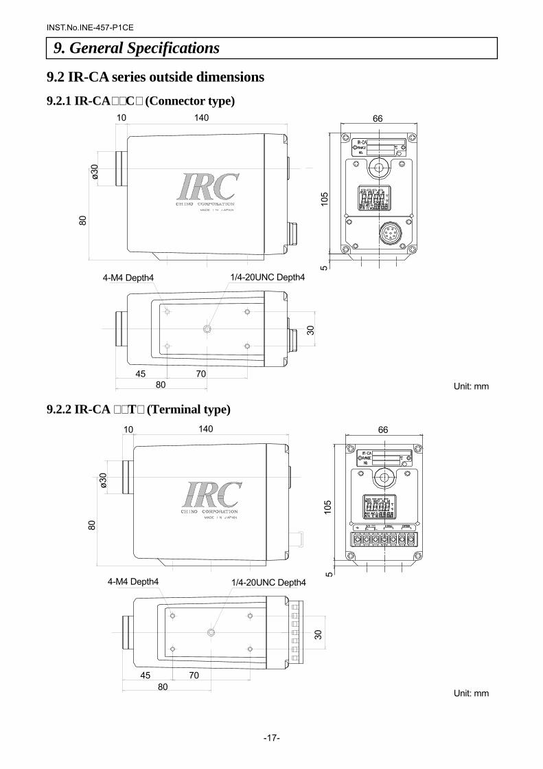
9.2 IR-CA series outside dimensions
9.2.1 IR-CA C (Connector type) 9.2.2 IR-CA T (Terminal type)
9. General Specifications
4-M4 Depth4
10 140 66
45 80
70
80
ø30
30
5 10
5
1/4-20UNC Depth4
4-M4 Depth4
10 140 66
45 80
70
80
ø30
30
5 10
5
1/4-20UNC Depth4
Unit: mm
Unit: mm
INST.No.INE-457-P1CE
-18-
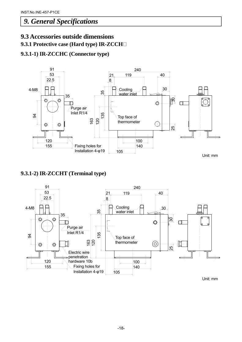
9.3 Accessories outside dimensions 9.3.1 Protective case (Hard type) IR-ZCCH
9.3.1-1) IR-ZCCHC (Connector type)
9.3.1-2) IR-ZCCHT (Terminal type)
9. General Specifications
91 53 22.5
4-M8
35
120 155
24021 119 40 8
30
100140
105
94
163
120
135
25
30
35
Fixing holes for Installation 4-φ19
Cooling water inlet
Purge air Inlet R1/4
Electric wire penetration hardware 10b
Top face of thermometer
91 53
22.5
4-M8 35
94
120 155
240119 40 21
8
30
100140
105
163
120 13
5 35
25
30
Cooling water inlet
Top face of thermometer
Fixing holes for Installation 4-φ19
Purge air Inlet R1/4
Unit: mm
Unit: mm
INST.No.INE-457-P1CE
-19-
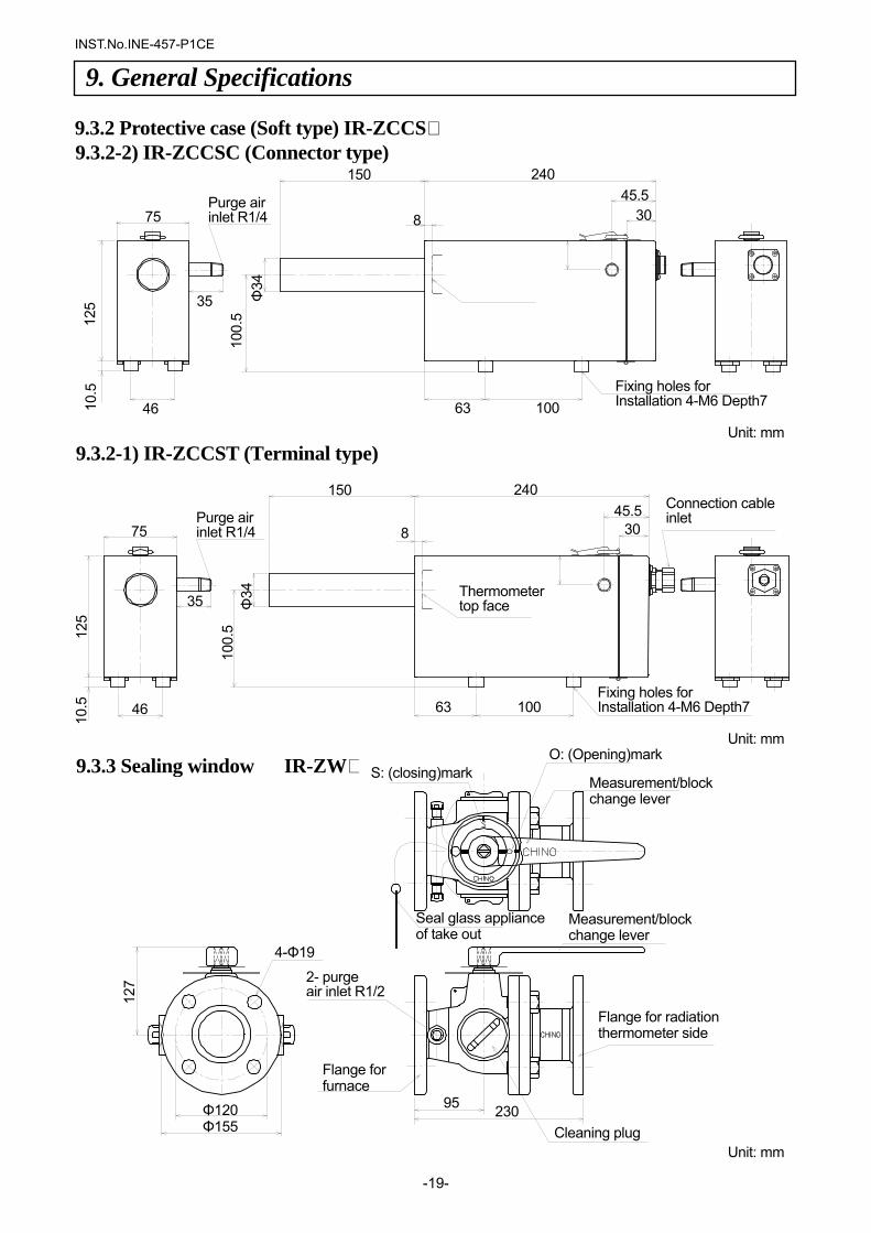
9.3.2 Protective case (Soft type) IR-ZCCS
9. General Specifications 12
5
75
10.5
46
35
150 24045.5
30
63 100
8
Φ34
10
0.5
9.3.2-1) IR-ZCCST (Terminal type)
Connection cableinlet
Thermometer top face
Fixing holes for Installation 4-M6 Depth7
Purge air inlet R1/4
127
95 230Φ120 Φ155
4-Φ19
2- purge air inlet R1/2
Flange for furnace
Cleaning plug
Flange for radiation thermometer side
Measurement/block change lever
Measurement/block change lever
S: (closing)mark
Seal glass appliance of take out
9.3.3 Sealing window IR-ZW O: (Opening)mark
9.3.2-2) IR-ZCCSC (Connector type) 150 240
45.5 30
63 100
75
125
10.5
46
35
100.
5 Φ
34
8Purge air inlet R1/4
Fixing holes for Installation 4-M6 Depth7
Unit: mm
Unit: mm
Unit: mm
INST.No.INE-457-P1CE
-20-
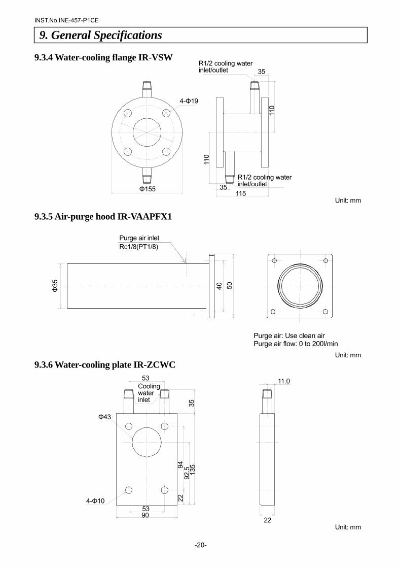
9.3.4 Water-cooling flange IR-VSW 9.3.5 Air-purge hood IR-VAAPFX1 9.3.6 Water-cooling plate IR-ZCWC
9. General Specifications Φ
35
53
Φ43
4-Φ10 53 90
35
135
92.5
94
22
11.0
22
Cooling water inlet
Purge air inlet Rc1/8(PT1/8)
35
35115Φ155
4-Φ19
110
110
R1/2 cooling water inlet/outlet
R1/2 cooling water inlet/outlet
40
50
Purge air: Use clean air Purge air flow: 0 to 200l/min
Unit: mm
Unit: mm
Unit: mm
INST.No.INE-457-P1CE
-21-
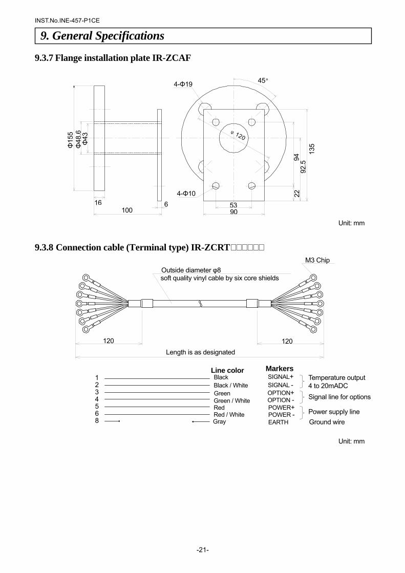
φ120
Φ15
5 Φ
48.6
Φ
43
16 100
64-Φ10
5390
22
94
92.5
13
5
45°4-Φ19
Black SIGNAL+ SIGNAL - OPTION+
POWER+
Gray EARTH
Markers Line color
Black / White GreenGreen / WhiteRed Red / White
OPTION -
POWER -
Temperature output 4 to 20mADC
Signal line for options
Power supply line Ground wire
1 2 3 4 5 6 8
120 120
Outside diameter φ8 soft quality vinyl cable by six core shields
M3 Chip
Length is as designated
9.3.7 Flange installation plate IR-ZCAF
9.3.8 Connection cable (Terminal type) IR-ZCRT
9. General Specifications
Unit: mm
Unit: mm
INST.No.INE-457-P1CE
-22-
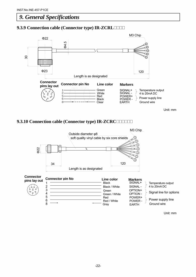
9.3.9 Connection cable (Connector type) IR-ZCRL 9.3.10 Connection cable (Connector type) IR-ZCRC
9. General Specifications
Φ22
34 120
Outside diameter φ8 soft quality vinyl cable by six core shields
M3 Chip
Length is as designated
Markers Line color Black SIGNAL+
SIGNAL - OPTION+
POWER+
Gray EARTH
Black / White GreenGreen / WhiteRed Red / White
OPTION -
POWER -
Temperature output 4 to 20mA DC
Signal line for options
Power supply line Ground wire
Connector pins lay out
1 2 3 4 5 6 8
Connector pin No
12568
M3 Chip
120 Length is as designated
Φ22
Φ23
30
Φ4.
5
Connector pins lay out Connector pin No Markers Line color
EARTH
SIGNAL+ SIGNAL -
GreenWhiteRed Black
POWER+ POWER - Power supply line
Ground wire Clear
Temperature output4 to 20mA DC
Unit: mm
Unit: mm
INST.No.INE-457-P1CE
-23-
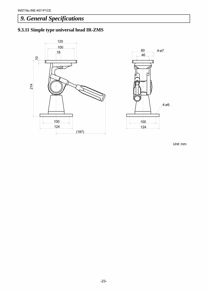
9.3.11 Simple type universal head IR-ZMS
9. General Specifications
120
100 18
124 100
(187)
214
10
8046
100 124
4-ø7
4-ø9
Unit: mm

32-8, KUMANO-CHO, ITABASHI-KU, TOKYO 173-8632
Telephone: +81-3-3956-2171 Facsimile: +81-3-3956-0915 Web site http://www.chino.co.jp/
INE-457-P1CE Jan-'05 IR-CA Series Single color radiation thermometer fixed focus type [Hardware volume] Model for IR-CAB, IR-CAE, IR-CAM, IR-CAN (Printed in Japan)