Embed Size (px)
Citation preview
NWE NETWORK ENGINEERING OY AB VAT: FI 09628099 1 Uppstutåget 2 Tel: + 358 622 50 114 FIN-64200 Närpes, FINLAND www.nwe.fi [email protected]
FIX ROAD® & FIX STRAP® cargo securing systems
Mounting Instructions
Assembly instructions for the FIX Road® and FIX Strap® systems
Before you start:
• Mounting of the rails in FIX Load Securing system should be done by two
persons to improve result and avoid injuries.
• The rails need to be mounted as high as possible with the opening facing
inwards.
• Check that eventual moving roof, side curtain and beams etc. has enough
space for the operation and make sure eventual locking device and side doors
can move freely.
NWE NETWORK ENGINEERING OY AB VAT: FI 09628099 2 Uppstutåget 2 Tel: + 358 622 50 114 FIN-64200 Närpes, FINLAND www.nwe.fi [email protected]
Installation:
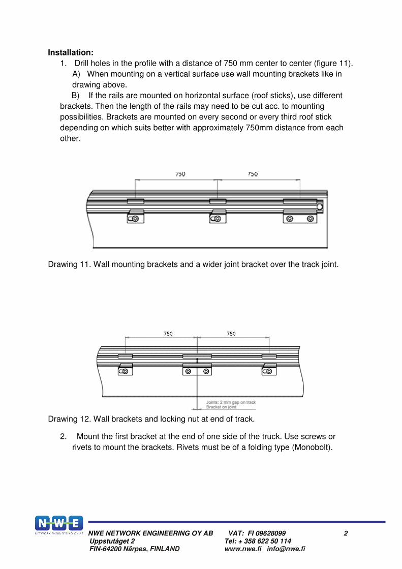
1. Drill holes in the profile with a distance of 750 mm center to center (figure 11).
A) When mounting on a vertical surface use wall mounting brackets like in
drawing above.
B) If the rails are mounted on horizontal surface (roof sticks), use different
brackets. Then the length of the rails may need to be cut acc. to mounting
possibilities. Brackets are mounted on every second or every third roof stick
depending on which suits better with approximately 750mm distance from each
other.
Drawing 11. Wall mounting brackets and a wider joint bracket over the track joint.
Drawing 12. Wall brackets and locking nut at end of track.
2. Mount the first bracket at the end of one side of the truck. Use screws or
rivets to mount the brackets. Rivets must be of a folding type (Monobolt).
NWE NETWORK ENGINEERING OY AB VAT: FI 09628099 3 Uppstutåget 2 Tel: + 358 622 50 114 FIN-64200 Närpes, FINLAND www.nwe.fi [email protected]
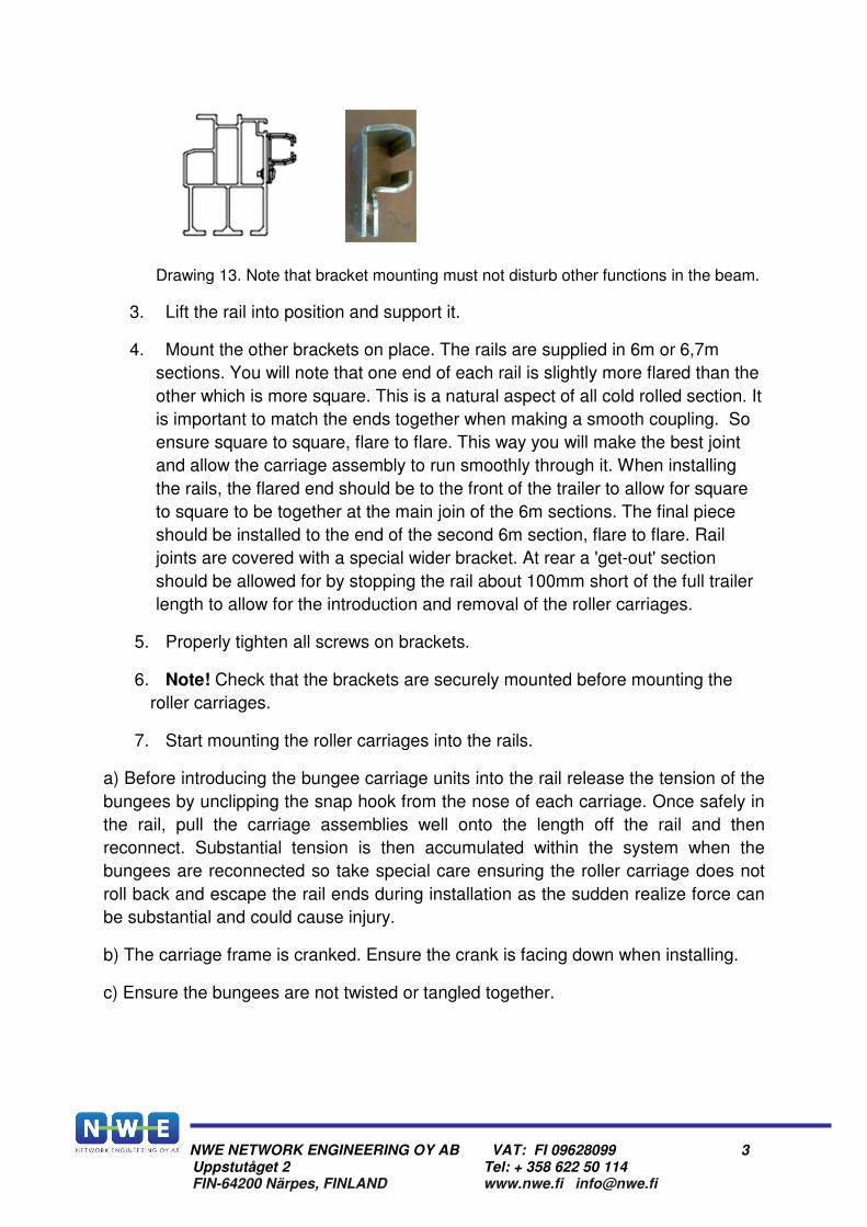
Drawing 13. Note that bracket mounting must not disturb other functions in the beam.
3. Lift the rail into position and support it.
4. Mount the other brackets on place. The rails are supplied in 6m or 6,7m
sections. You will note that one end of each rail is slightly more flared than the
other which is more square. This is a natural aspect of all cold rolled section. It
is important to match the ends together when making a smooth coupling. So
ensure square to square, flare to flare. This way you will make the best joint
and allow the carriage assembly to run smoothly through it. When installing
the rails, the flared end should be to the front of the trailer to allow for square
to square to be together at the main join of the 6m sections. The final piece
should be installed to the end of the second 6m section, flare to flare. Rail
joints are covered with a special wider bracket. At rear a 'get-out' section
should be allowed for by stopping the rail about 100mm short of the full trailer
length to allow for the introduction and removal of the roller carriages.
5. Properly tighten all screws on brackets.
6. Note! Check that the brackets are securely mounted before mounting the
roller carriages.
7. Start mounting the roller carriages into the rails.
a) Before introducing the bungee carriage units into the rail release the tension of the
bungees by unclipping the snap hook from the nose of each carriage. Once safely in
the rail, pull the carriage assemblies well onto the length off the rail and then
reconnect. Substantial tension is then accumulated within the system when the
bungees are reconnected so take special care ensuring the roller carriage does not
roll back and escape the rail ends during installation as the sudden realize force can
be substantial and could cause injury.
b) The carriage frame is cranked. Ensure the crank is facing down when installing.
c) Ensure the bungees are not twisted or tangled together.
NWE NETWORK ENGINEERING OY AB VAT: FI 09628099 4 Uppstutåget 2 Tel: + 358 622 50 114 FIN-64200 Närpes, FINLAND www.nwe.fi [email protected]
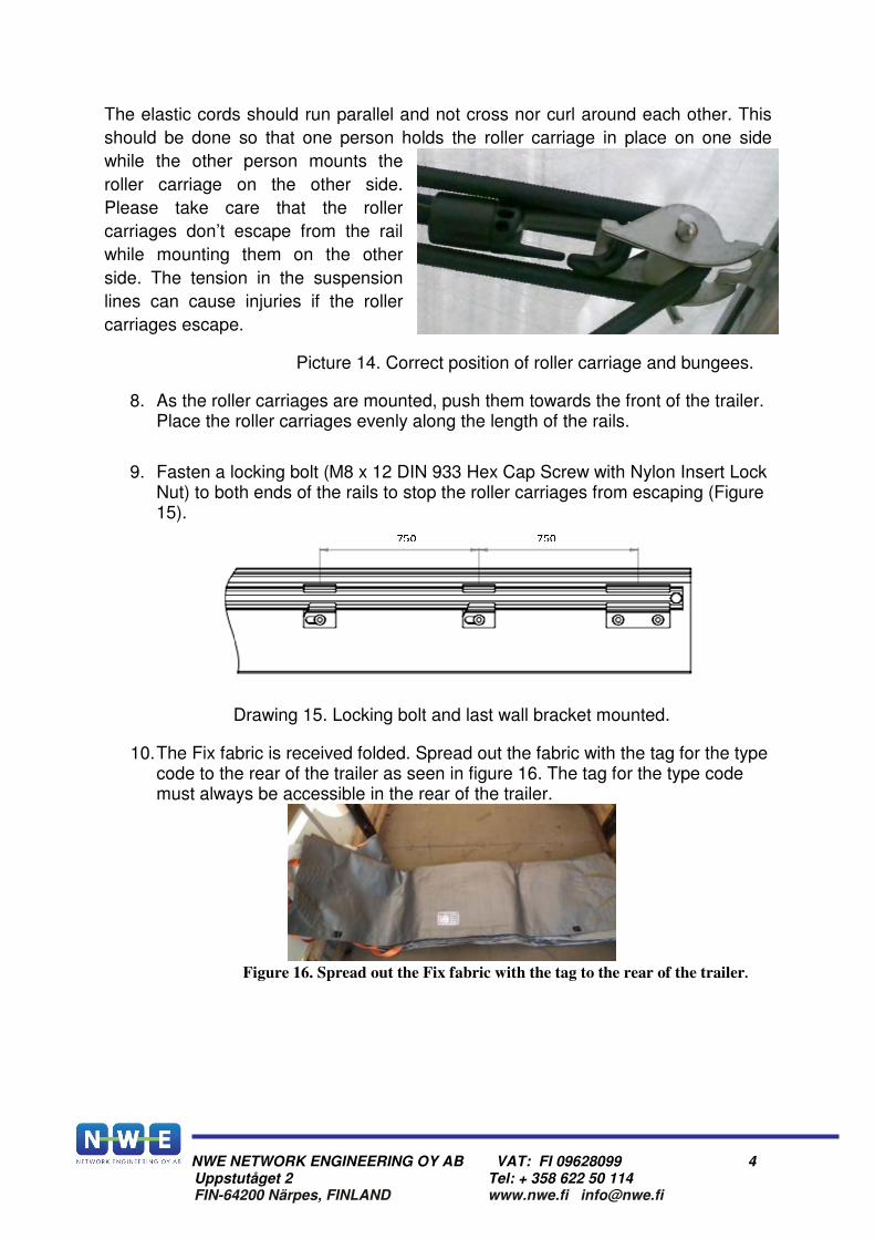
The elastic cords should run parallel and not cross nor curl around each other. This
should be done so that one person holds the roller carriage in place on one side
while the other person mounts the
roller carriage on the other side.
Please take care that the roller
carriages don’t escape from the rail
while mounting them on the other
side. The tension in the suspension
lines can cause injuries if the roller
carriages escape.
Picture 14. Correct position of roller carriage and bungees.
8. As the roller carriages are mounted, push them towards the front of the trailer. Place the roller carriages evenly along the length of the rails.
9. Fasten a locking bolt (M8 x 12 DIN 933 Hex Cap Screw with Nylon Insert Lock Nut) to both ends of the rails to stop the roller carriages from escaping (Figure 15).
Drawing 15. Locking bolt and last wall bracket mounted.
10. The Fix fabric is received folded. Spread out the fabric with the tag for the type code to the rear of the trailer as seen in figure 16. The tag for the type code must always be accessible in the rear of the trailer.
Figure 16. Spread out the Fix fabric with the tag to the rear of the trailer.
NWE NETWORK ENGINEERING OY AB VAT: FI 09628099 5 Uppstutåget 2 Tel: + 358 622 50 114 FIN-64200 Närpes, FINLAND www.nwe.fi [email protected]
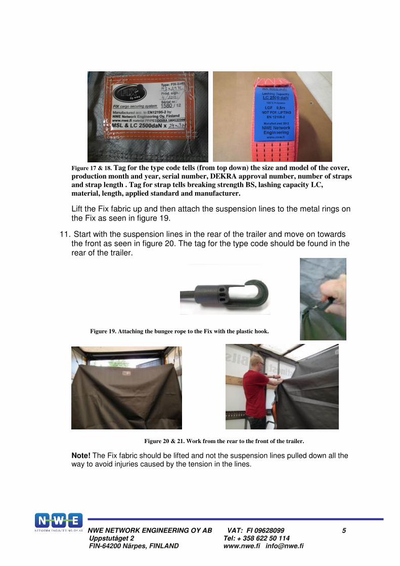
Figure 17 & 18. Tag for the type code tells (from top down) the size and model of the cover,
production month and year, serial number, DEKRA approval number, number of straps
and strap length . Tag for strap tells breaking strength BS, lashing capacity LC,
material, length, applied standard and manufacturer.
Lift the Fix fabric up and then attach the suspension lines to the metal rings on the Fix as seen in figure 19.
11. Start with the suspension lines in the rear of the trailer and move on towards the front as seen in figure 20. The tag for the type code should be found in the rear of the trailer.
Figure 19. Attaching the bungee rope to the Fix with the plastic hook.
Figure 20 & 21. Work from the rear to the front of the trailer.
Note! The Fix fabric should be lifted and not the suspension lines pulled down all the way to avoid injuries caused by the tension in the lines.
NWE NETWORK ENGINEERING OY AB VAT: FI 09628099 6 Uppstutåget 2 Tel: + 358 622 50 114 FIN-64200 Närpes, FINLAND www.nwe.fi [email protected]
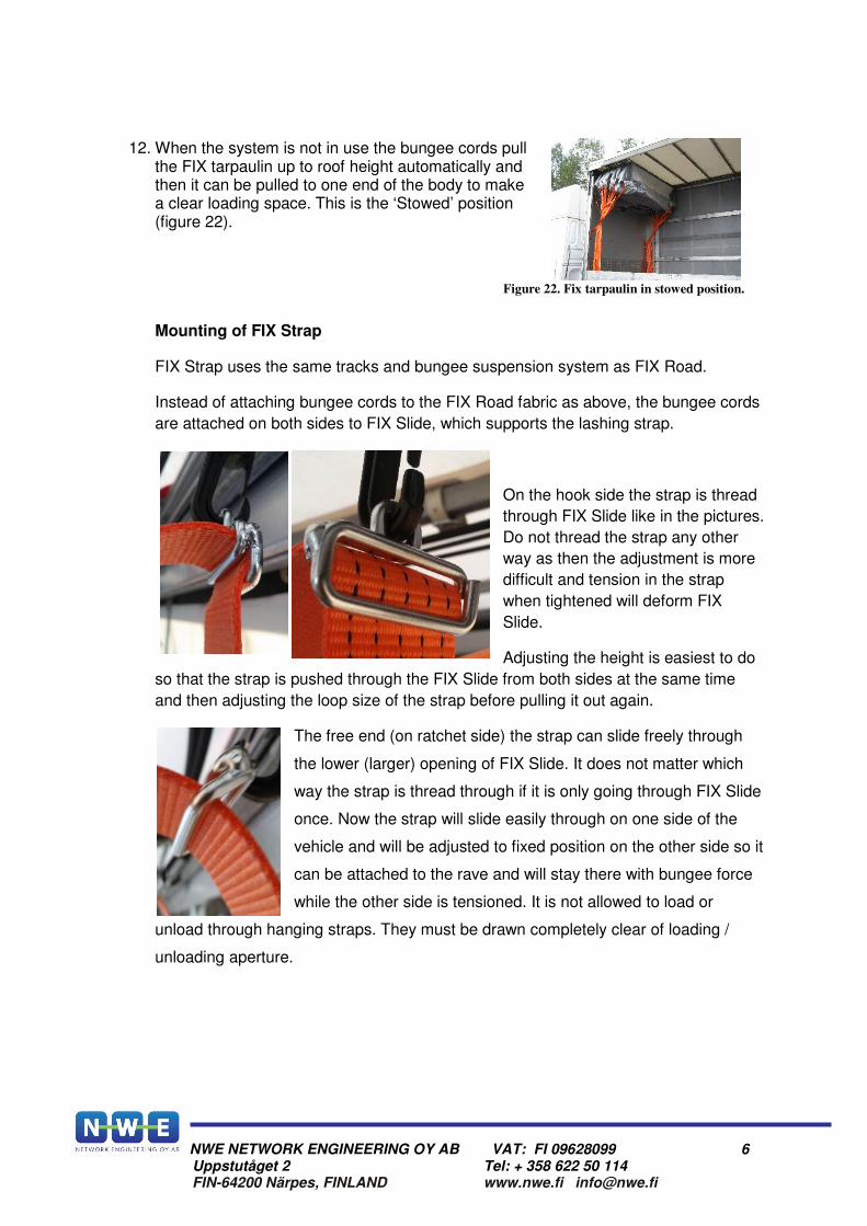
12. When the system is not in use the bungee cords pull the FIX tarpaulin up to roof height automatically and then it can be pulled to one end of the body to make a clear loading space. This is the ‘Stowed’ position (figure 22).
Figure 22. Fix tarpaulin in stowed position.
Mounting of FIX Strap
FIX Strap uses the same tracks and bungee suspension system as FIX Road.
Instead of attaching bungee cords to the FIX Road fabric as above, the bungee cords
are attached on both sides to FIX Slide, which supports the lashing strap.
On the hook side the strap is thread
through FIX Slide like in the pictures.
Do not thread the strap any other
way as then the adjustment is more
difficult and tension in the strap
when tightened will deform FIX
Slide.
Adjusting the height is easiest to do
so that the strap is pushed through the FIX Slide from both sides at the same time
and then adjusting the loop size of the strap before pulling it out again.
The free end (on ratchet side) the strap can slide freely through
the lower (larger) opening of FIX Slide. It does not matter which
way the strap is thread through if it is only going through FIX Slide
once. Now the strap will slide easily through on one side of the
vehicle and will be adjusted to fixed position on the other side so it
can be attached to the rave and will stay there with bungee force
while the other side is tensioned. It is not allowed to load or
unload through hanging straps. They must be drawn completely clear of loading /
unloading aperture.
NWE NETWORK ENGINEERING OY AB VAT: FI 09628099 7 Uppstutåget 2 Tel: + 358 622 50 114 FIN-64200 Närpes, FINLAND www.nwe.fi [email protected]
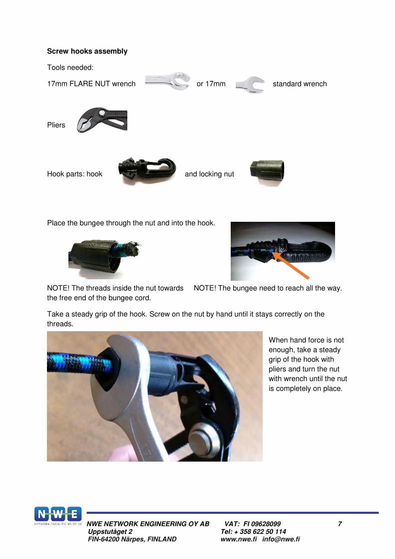
Screw hooks assembly
Tools needed:
17mm FLARE NUT wrench or 17mm standard wrench
Pliers
Hook parts: hook and locking nut
Place the bungee through the nut and into the hook.
NOTE! The threads inside the nut towards NOTE! The bungee need to reach all the way.
the free end of the bungee cord.
Take a steady grip of the hook. Screw on the nut by hand until it stays correctly on the
threads.
When hand force is not
enough, take a steady
grip of the hook with
pliers and turn the nut
with wrench until the nut
is completely on place.
NWE NETWORK ENGINEERING OY AB VAT: FI 09628099 8 Uppstutåget 2 Tel: + 358 622 50 114 FIN-64200 Närpes, FINLAND www.nwe.fi [email protected]
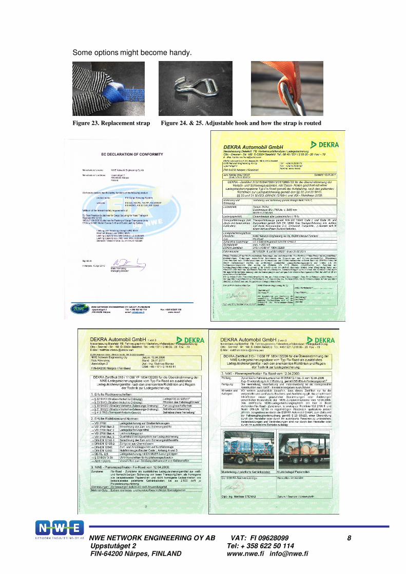
Some options might become handy.
Figure 23. Replacement strap Figure 24. & 25. Adjustable hook and how the strap is routed