Embed Size (px)
Citation preview

CS351
© 2003 Ray S. Babcock
Five UML Views of a System
DESIGN
PROCESS DEPLOYMENT
IMPLEMENTATION
USE CASE

CS351
© 2003 Ray S. Babcock
UML Views of a System
The architecture of a system is the fundamental organization of the system as a whole.
The five UML Views:● Use Case View: focuses on scenarios● Design View: focuses on the vocabulary● Process View: focuses on timing & control● Implementation View: focuses on physical
system● Deployment View: focuses on geographic
distribution.
CS351
© 2003 Ray S. Babcock
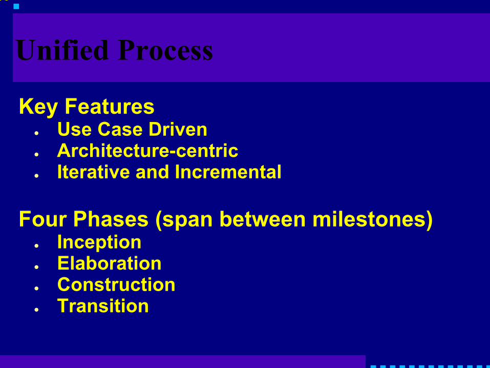
Unified Process
Key Features● Use Case Driven● Architecture-centric● Iterative and Incremental
Four Phases (span between milestones)● Inception● Elaboration● Construction● Transition
CS351
© 2003 Ray S. Babcock
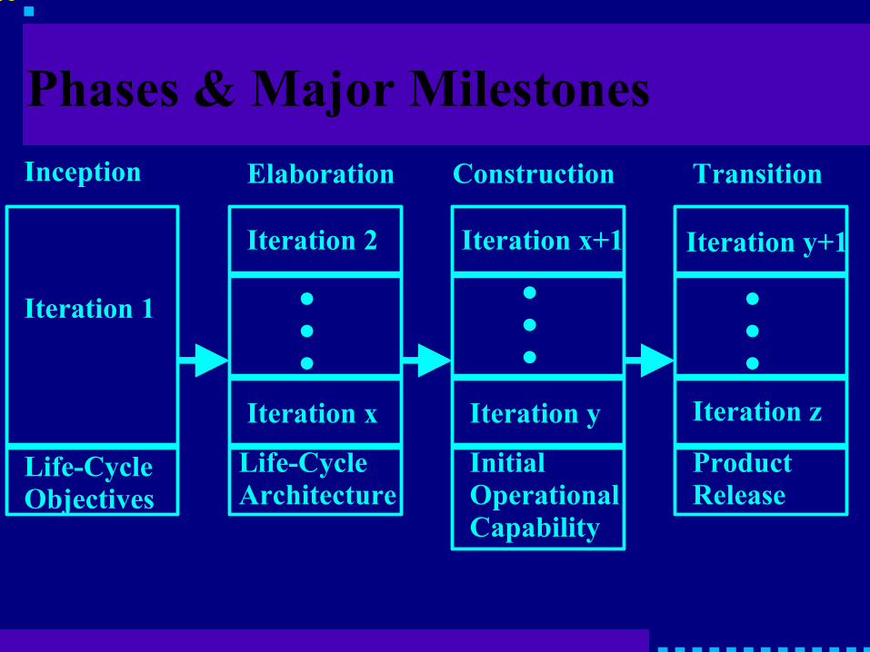
Phases & Major MilestonesInception Elaboration Construction Transition
Life-CycleObjectives
Life-CycleArchitecture
Initial Operational Capability
ProductRelease
Iteration 1
Iteration 2 Iteration x+1 Iteration y+1
Iteration x Iteration y Iteration z
●●●
●●●
●●●

CS351
© 2003 Ray S. Babcock
Inception
Primary goal is to establish the case for the viability of the proposed system.
● Define the scope of the system.● Outline a candidate architecture.● Identify critical risks and how to address
them.● Start to make the business case that the
project is worth doing based on initial estimates of cost, effort, schedule, and product quality.
CS351
© 2003 Ray S. Babcock
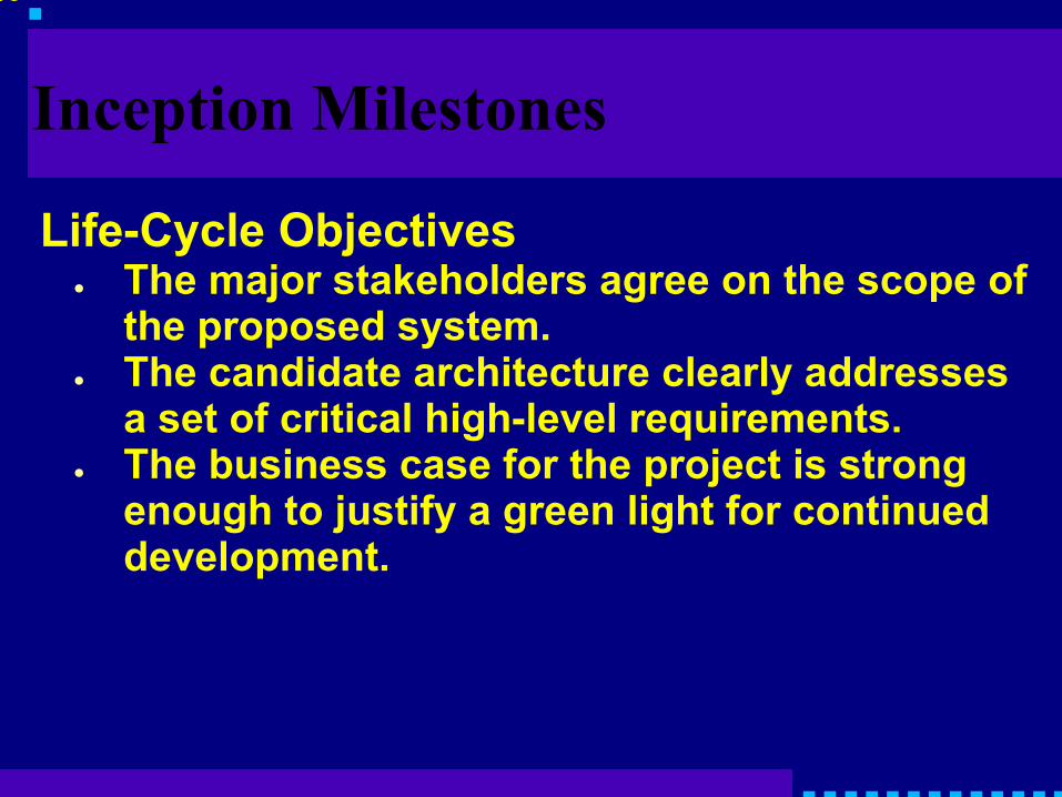
Inception Milestones
Life-Cycle Objectives● The major stakeholders agree on the scope of
the proposed system.● The candidate architecture clearly addresses
a set of critical high-level requirements.● The business case for the project is strong
enough to justify a green light for continued development.

CS351
© 2003 Ray S. Babcock
ElaborationPrimary goal is to establish the ability to
build the new system given the financial constraints, schedule constraints, and other kinds of constraints.
● Capture a healthy majority of the remaining requirements.
● Expand the candidate architecture into a full architectural baseline (internal release of the system focused on describing the architecture).
● Address the risks on an ongoing basis.● Finalize the business case, prepare a project
plan.

CS351
© 2003 Ray S. Babcock
Elaboration Milestones
Life-Cycle Architecture● Most of the functional requirements for the
new system have been captured in the use case model
● The architectural baseline is a small, skinny system that will serve as a solid foundation for ongoing development.
● The business case has received a green light, and the project team has an initial project plan that describes how the Construction phase will proceed.
CS351
© 2003 Ray S. Babcock
Construction
Primary goal is to build the system that is capable of operating successfully in beta customer environments.
The major milestone is called the Initial Operational Capability. More or less fully operational in beta customer's hands.

CS351
© 2003 Ray S. Babcock
Transition
Primary goal is to roll out the fully functional system to customers.
The major milestone is called the Product Release.

CS351
© 2003 Ray S. Babcock
Five Work Flows
Each work flow is a set of activities that various project workers perform.
● Requirements● Analysis ● Design● Implementation● Test
These five work flows are associated with six kinds of UML models.
CS351
© 2003 Ray S. Babcock
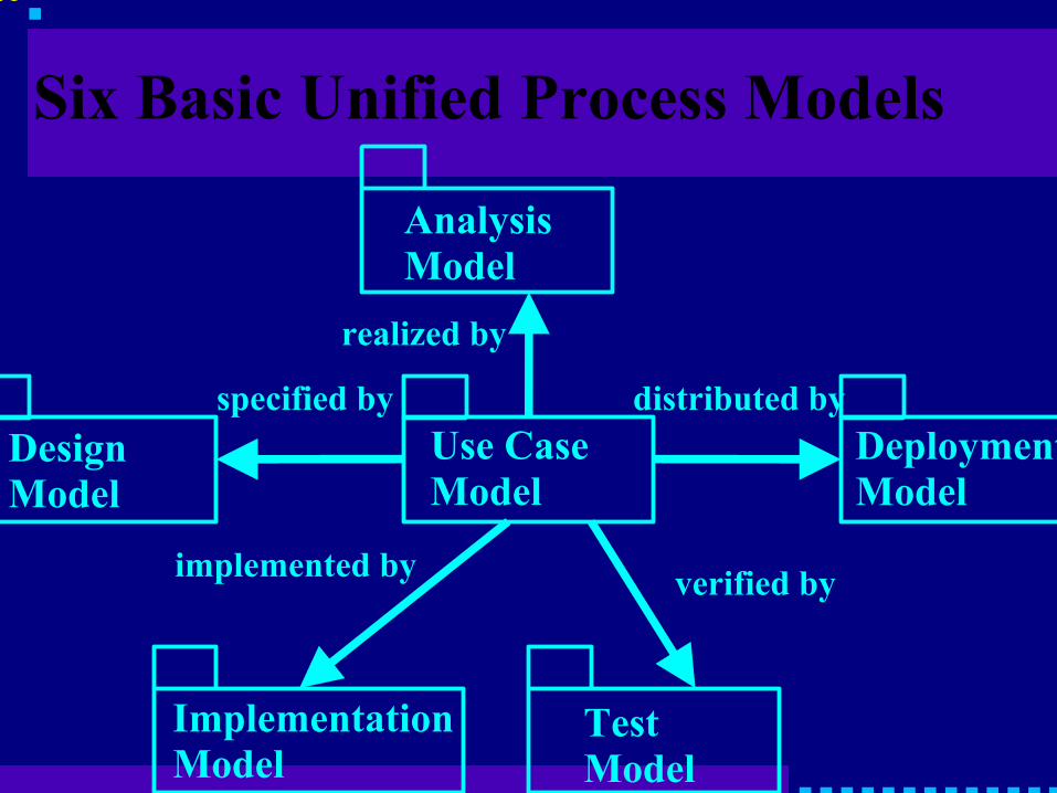
Six Basic Unified Process Models
AnalysisModel
DesignModel
Use CaseModel
DeploymentModel
ImplementationModel
TestModel
realized by
specified by
implemented by verified by
distributed by

CS351
© 2003 Ray S. Babcock
Requirements Work Flow
● Aimed at building the Use Case Model.● Captures the functional requirements of
the system being modeled.● Serves as the foundation for all other
development work (see previous slide)● Prototyping activities are a part of the
requirements work flow.
CS351
© 2003 Ray S. Babcock
Analysis Work Flow
● Aimed at building the Analysis Model.● Helps developers refine and structure the
functional requirements captured in the use case model.
● Realizations of the use cases that lend themselves better to design and implementation.

CS351
© 2003 Ray S. Babcock
Design Work Flow
● Aimed at building the Design Model.● Describe the physical realizations of the
use cases.● Describe the physical realizations of the
contents of the analysis model.● Serves as an abstraction of the
implementation model.● Also focuses on the Deployment Model
which defines the physical organization of the system in terms of computational nodes.

CS351
© 2003 Ray S. Babcock
Implementation Work Flow
● Aimed at building the Implementation Model.● Describes how the elements of the design
model are packaged into software components.
● source code files● dynamic link libraries (dlls)● enterprise Java Beans (ejbs)

CS351
© 2003 Ray S. Babcock
Test Work Flow
● Aimed at building the Test Model● Describes how integration and system
tests will exercise executable components from the implementation model.
● Describes how the team will perform tests.
The test model contains test cases often derived directly from the use cases.

CS351
© 2003 Ray S. Babcock
Identifying Relevant Real-World Things
An object is simply a real-world thing or concept.
● An object has identity. Generally takes the form of a human-readable name.
● An object has state. The various properties that describe the object (attributes) and the values of those attributes at some point in time.
● An object has behavior. Represented by functions (methods) that use or change attributes.

CS351
© 2003 Ray S. Babcock
Classes
A class is a collection of objects that have the same characteristics.
An object that belongs to a particular class is often referred to as an instance of that class.
UML's standard notation is a box with three parts (seen before).

CS351
© 2003 Ray S. Babcock
UML Class Notations
Class
Attributes
Operations
Class
Class
Operations
Class
Attributes

CS351
© 2003 Ray S. Babcock
Class Relationships
Associations● Structural connection between classes.● Shown as a line between classes.● If no arrow, then the association is
bidirectional.● Can have adornments
● Name: indicating nature of relationship.● Roles: the faces that classes present to other
classes.● Multiplicity: How many objects associated with
each class can be present within the association.Fixed Value (1 or 3) Range of values (3..*)Many (*) Set of values (2,4,6,8)
CS351
© 2003 Ray S. Babcock
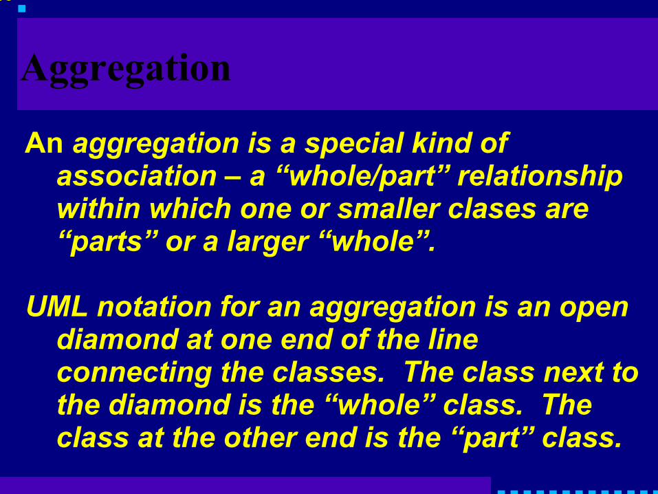
Aggregation
An aggregation is a special kind of association – a “whole/part” relationship within which one or smaller clases are “parts” or a larger “whole”.
UML notation for an aggregation is an open diamond at one end of the line connecting the classes. The class next to the diamond is the “whole” class. The class at the other end is the “part” class.

CS351
© 2003 Ray S. Babcock
WHOLE CLASS
PART CLASS
AGGREGATION

CS351
© 2003 Ray S. Babcock
Generalization
Generalization refers to a relationship between a general class (the superclass or parent) and a more specific version of that class (the subclass or child).
The subclass is a kind of the superclass.
A subclass inherits the attributes and operations from one super class (single inheritance) or from more than one (multiple inheritance).

CS351
© 2003 Ray S. Babcock
Generalization (cont.)
Two important principles of generalization:
● Substitutability states that an object of a subclass may be substituted anywhere an object of an associated superclass is used.
● Polymorphism states that an object of a subclass can redefine any of the operations it inherits from its superclass(es).

CS351
© 2003 Ray S. Babcock
UML Generalization Notation
Parent Class
Child Class

CS351
© 2003 Ray S. Babcock
Association Classes
An association class is a cross between an association and a class. You use it to model an association that has interesting characteristics of its own outside the classes it connects.
It is handy to break a many-to-many relationship into a set of one-to-many relationships.

CS351
© 2003 Ray S. Babcock
UML Association Class Notation
Class 1 Class 2
AssociationClass

CS351
© 2003 Ray S. Babcock
Association Class ExampleOnline Bookstore
Author Book
BookAndAuthor
title:String
role

CS351
© 2003 Ray S. Babcock
Example notes
● Normally there would be a many-many relationship between Author and Book.
● An Author may have written more than one Book.
● A Book may have one or more Authors.● The presence of the BookAndAuthor
association class allows us to pair one Author with one Book. The role attribute gives us the option of stating whether the Author was the primary or supporting author or something else (editor).

CS351
© 2003 Ray S. Babcock
UML Class Diagram
A class diagram shows classes and the various relationships in which they are involved.
Class diagrams are the primary means by which you show the structure of a system being developed.

CS351
© 2003 Ray S. Babcock
Class Diagram ExampleOnline Bookstore
BookAndAuthorrole
Author Book
title:String
Publisher
ReviewReviewerwrites
is rated by
Shipping Info
Order Billing Info
Customer
Customer ReviewEditorial Review
Shipper
name
Accountemail addres, IDpassword
verifyPassword()1
1assignRatiing(rating:Int)computeAvgRating():Double
1
*

CS351
© 2003 Ray S. Babcock
Object Diagrams
Similar to Class diagram with name of the class to which object belongs after a colon and contents of top box underlined.

CS351
© 2003 Ray S. Babcock
Sample Object DiagramOnline Bookstore
:BookAndAuthor
role=”supporting author”
:Authorname=”Kendall Scott”
:Booktitle=”Uml Distilled”
AW:Publishername=”Addison Wesley”
Only 1 of the four objects has a name. The others are anonymous.

CS351
© 2003 Ray S. Babcock
UML Notes
Class
Text or hyperlink to another document

CS351
© 2003 Ray S. Babcock
UML Packages
A grouping of pieces of a model.

CS351
© 2003 Ray S. Babcock
Capturing Requirements
ACTORS AND USE CASES. An actorrepresenents one of two things:
● A role that a user can play with regard to the system.
● An entity, such as another system or a database, that resides outside the system.
Actor

CS351
© 2003 Ray S. Babcock
Sample Actors
Customer Shipping System Accountant

CS351
© 2003 Ray S. Babcock
Use Cases
A use case is a sequence of actions that an actor performs within a system to achieve a particular goal.
● Search by Author● Produce Shipping Manifest● Pring GL Report

CS351
© 2003 Ray S. Babcock
Sample Use Cases
Search By Author
Produce Shipping Manifest
Print GL Report

CS351
© 2003 Ray S. Babcock
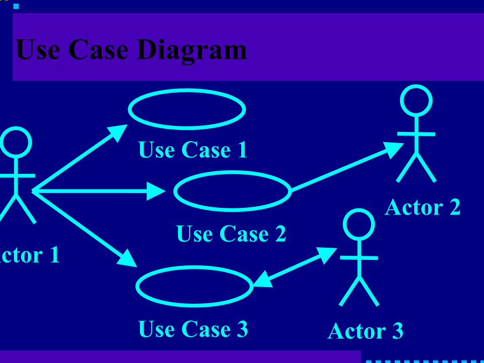
UML Use Case Diagrams
Putting actors together with use cases produces a use case diagram.
● The actor that executes a given use case usually appears on the lef-hand side.
● The use cases appear in the center.● Any other actors that are involved in the
given use cases tend to appear on the right-hand side.
● Arrows show which actors are involved in which use cases.
CS351
© 2003 Ray S. Babcock
Use Case Diagram
Actor 1
Actor 2
Actor 3
Use Case 1
Use Case 2
Use Case 3

CS351
© 2003 Ray S. Babcock
Sample Use Case DiagramOnline Bookstore
Customer
Create Account
Log In
Write Customer Review
Add Book To Shopping Chart
Check Out

CS351
© 2003 Ray S. Babcock
Flow Of Events
The text of a use case describes possible paths through the use case.
● Main Flow Of Events● Exceptional Flow Of Events (Alternate
Course Of Action)

CS351
© 2003 Ray S. Babcock
Sample Flow Of EventsOnline Bookstore
Log InThe Customer clicks the Login button on the
Home page. The system displays the Login page. The customer enters his or her user ID and password, and then clicks the OK button. The system validates the login information against the persistent Account data, and then returns the Customer to the Home Page.

CS351
© 2003 Ray S. Babcock
Organizing Use Cases
IncludeWithin an include relationship, one use case
explicitly includes the behavior of another use case at a specified point within a course of action.
The included use case doesn't stand alone.
<<include>>
Base Use Case Included Use Case

CS351
© 2003 Ray S. Babcock
Sample Include RelationshipOnline Bookstore
Add to Wish List
Check Out
Log In
<<include>>
<<include>>

CS351
© 2003 Ray S. Babcock
Organizing Use Cases (cont.)Extend
Within an extend relationship, a base use case Implicitly includes the behavior of another use case at one or more specified points. The points are called extension points.
You generally use this construct to factor out behavior that's optional or that occurs only under certain conditions.
<<extend>>(value 1)Base Use Case Extended Use Case

CS351
© 2003 Ray S. Babcock
Sample Extend RelationshipOnline Bookstore
Check Order Statusextension points
order ID
Cancel Order<<extend>>(order ID)
Customer has the option of cancelling an order in conjunction with checking status of that order

CS351
© 2003 Ray S. Babcock
Read More
Project-Based Software Engineering by Evelyn Stiller and Cathie LeBlanc
Advanced Use Case Modeling, Software Systems by Frank Armour and Granville Miller