Embed Size (px)
Citation preview

FITTING INSTRUCTIONSTO BE FITTED BY A QUALIFIED TECHNICIANYZF R6 2006-2019
Secondary Alternator Cover Part No. EC-R6-2008-1-GBR / Secondary Clutch Cover Part No. EC-R6-2008-2-GBR / Secondary Pulse Cover Part No. EC-R6-2008-3-GBR
Secondary Alternator Cover KIT Part No. EC-R6-2008-1-K-GBR / Bullet Frame Race Slider Set Part No. FS-R6-2006-R / Paddock Stand / Bobbin Set Part No. BA12-6-GBR-SET
Lower Chain Guard Part No. CGA10-GBR
THIS SHEET INCLUDES FITTING INSTRUCTIONS FOR THE FOLLOWING PARTS:
1 Remove the Fairing. 2 Remove 4 off existing bolts on the stock aluminium Alternator
cover, corresponding to the STOCK Secondary Engine Alternator Cover. Shown as bolt positions 1,2,3 & 4.
3 Place the STOCK Secondary Engine Alternator cover over the stock aluminium alternator cover. Loosely screw down all Bolt using the supplied M6 x 30mm replacement bolts.
4 Tighten all 4 bolts to a torque of 10 N/m as per manufacturer’s recommendations. DO NOT OVERTIGHTEN
5 Refitthefairing.
Bolt 4M6x30
A2 -10Nm
Bolt 3M6x30
A2 - 10Nm
Bolt 2M6x30 A2 - 10Nm
Bolt 1M6x30 A2 - 10Nm
SECONDARY ALTERNATOR COVER PART NO. EC-R6-2008-1-GBR
Bolt 4 Bolt 1
Bolt 2Bolt 3
www.GBRacing.eu
1 Remove the Fairing. 2 Remove 3 off existing bolts on the aluminium Clutch
cover, corresponding to the Secondary Engine Clutch Cover. Shown as bolt positions 1,2 & 3.
3 Place the Secondary Engine Clutch Cover over the stock aluminium clutch cover. Loosely screw down Bolt position 1 FIRST (Note: the moulded cover may need to be pushed to aid alignment), then bolts 2 & 3 using the supplied M6 x 50A2 & M6x35A2mm replacement bolts.
4 Tighten all 3 bolts to a torque of 10 N/m as per Manufacturer’s recommendations. DO NOT OVERTIGHTEN
5 Refitthefairing. Bolt 1M6x35 A2 - 10Nm
Bolt 2SPB10M6x50A2 - 10Nm
Bolt 3M6x35 A2 - 10Nm
SECONDARY CLUTCH COVER PART NO. EC-R6-2008-2-GBR
Bolt 1
Bolt 3
Bolt 2
1 Remove the Lower Fairing. 2 Remove 3 off existing bolts on the aluminium Pulse
cover, corresponding to the Secondary Engine Pulse Cover. Shown as bolt positions 1,2 & 3.
3 Place the Secondary Engine Pulse Cover over the stock aluminium pulse cover, holding the clutch cable steel bracket in place. Loosely screw down Bolts 2 & 3 with the supplied replacement M6 x 30 Bolts, lining up the steel bracket. Then the remaining supplied replacement M6 x 25mm Bolt.
4 Tighten all 3 bolts to a torque of 10 N/m as per Manufacturer’s recommendations. DO NOT OVERTIGHTEN
5 Reassemble the Lower fairing.
Bolt 1M6x25 A2- 10Nm
Bolt 2M6x30
A2 - 10Nm
Bolt 3M6x30 A2 - 10Nm
SECONDARY PULSE COVER PART NO. EC-R6-2008-3-GBR
1 Remove the Fairing. 2 Remove 4 off existing bolts on the aluminium KIT Alternator
cover, corresponding to the Secondary Engine KIT Alternator Cover. Shown as bolt positions 1,2,3 & 4.
3 Place the Secondary Engine KIT Alternator cover over the KIT aluminium KIT alternator cover. Loosely screw down Bolt position 1 (Note: the moulded cover may need to be pushed to aid alignment), then bolts 2, 3 & 4 using the supplied M6 x 35mm replacement bolts.
4 Tighten all 4 bolts to a torque of 10 N/m as per manufacturer’s recommendations. DO NOT OVERTIGHTEN
5 Refitthefairing.
Bolt 1M6x35
A2 - 10Nm
Bolt 2M6x35
A2 - 10Nm
Bolt 3M6x35 A2 - 10Nm
Bolt 4M6x35 A2 - 10Nm
SECONDARY ALTERNATOR COVER - KIT - PART NO. EC-R6-2008-1-K-GBR
Bolt 1 Bolt 4
Bolt 3
Bolt 2
KIT ONLY
Bolt 1Bolt 3
Bolt 2
FITTING INSTRUCTIONSTO BE FITTED BY A QUALIFIED TECHNICIAN
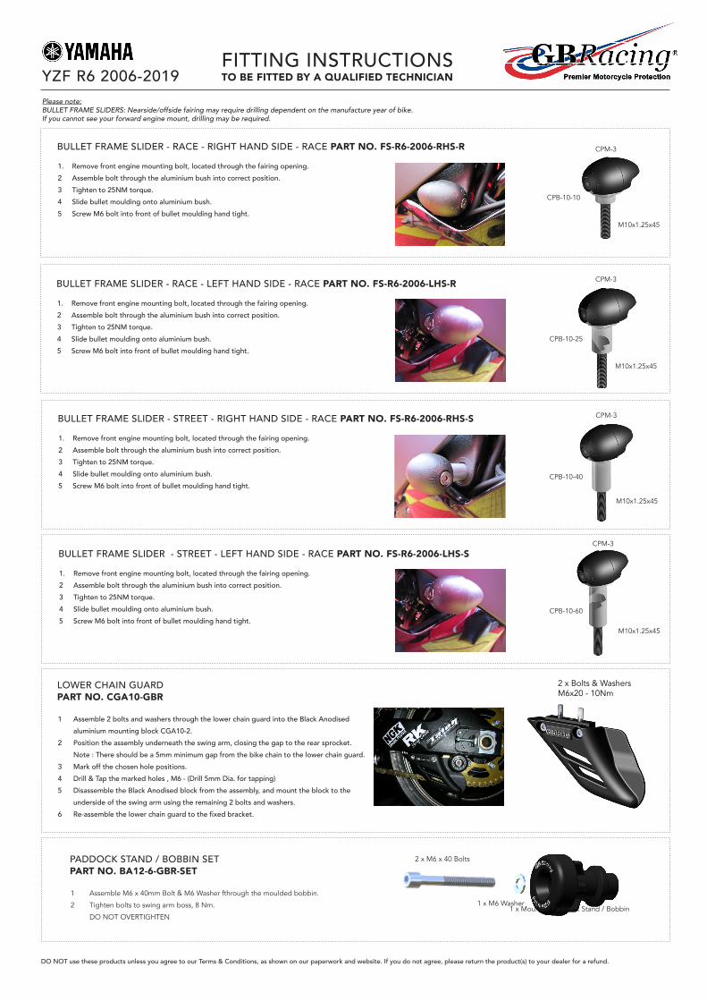
1. Remove front engine mounting bolt, located through the fairing opening.2 Assemble bolt through the aluminium bush into correct position.3 Tighten to 25NM torque.4 Slide bullet moulding onto aluminium bush.5 Screw M6 bolt into front of bullet moulding hand tight.
BULLET FRAME SLIDER - RACE - RIGHT HAND SIDE - RACE PART NO. FS-R6-2006-RHS-R
CPB-10-10
M10x1.25x45
CPM-3
1. Remove front engine mounting bolt, located through the fairing opening.2 Assemble bolt through the aluminium bush into correct position.3 Tighten to 25NM torque.4 Slide bullet moulding onto aluminium bush.5 Screw M6 bolt into front of bullet moulding hand tight.
BULLET FRAME SLIDER - RACE - LEFT HAND SIDE - RACE PART NO. FS-R6-2006-LHS-R
CPB-10-25
M10x1.25x45
CPM-3
1. Remove front engine mounting bolt, located through the fairing opening.2 Assemble bolt through the aluminium bush into correct position.3 Tighten to 25NM torque.4 Slide bullet moulding onto aluminium bush.5 Screw M6 bolt into front of bullet moulding hand tight.
BULLET FRAME SLIDER - STREET - RIGHT HAND SIDE - RACE PART NO. FS-R6-2006-RHS-S
CPB-10-40
M10x1.25x45
CPM-3
1. Remove front engine mounting bolt, located through the fairing opening.2 Assemble bolt through the aluminium bush into correct position.3 Tighten to 25NM torque.4 Slide bullet moulding onto aluminium bush.5 Screw M6 bolt into front of bullet moulding hand tight.
BULLET FRAME SLIDER - STREET - LEFT HAND SIDE - RACE PART NO. FS-R6-2006-LHS-S
CPB-10-60
M10x1.25x45
CPM-3
1 Assemble 2 bolts and washers through the lower chain guard into the Black Anodised aluminium mounting block CGA10-2.
2 Position the assembly underneath the swing arm, closing the gap to the rear sprocket. Note : There should be a 5mm minimum gap from the bike chain to the lower chain guard.3 Mark off the chosen hole positions.4 Drill & Tap the marked holes , M6 - (Drill 5mm Dia. for tapping)5 Disassemble the Black Anodised block from the assembly, and mount the block to the
underside of the swing arm using the remaining 2 bolts and washers. 6 Re-assemblethelowerchainguardtothefixedbracket.
LOWER CHAIN GUARD PART NO. CGA10-GBR
2 x Bolts & WashersM6x20 - 10Nm
YZF R6 2006-2019
DO NOT use these products unless you agree to our Terms & Conditions, as shown on our paperwork and website. If you do not agree, please return the product(s) to your dealer for a refund.
(1) Assemble M6 x 40mm Bolt & M6 Washer thru moulded bobbin.
(2) Tighten bolts to swing arm boss , 8 N/m.
Do not overtighten.
Fitting Instructions
To be fitted by a qualified Technician
1 off M6 x 40 Bolts
1 off Moulded Paddock stand/bobbin
BA12-6-GBR
1 off M6 Washer
(1) Assemble M6 x 40mm Bolt & M6 Washer thru moulded bobbin.
(2) Tighten bolts to swing arm boss , 8 N/m.
Do not overtighten.
Fitting Instructions
To be fitted by a qualified Technician
1 off M6 x 40 Bolts
1 off Moulded Paddock stand/bobbin
BA12-6-GBR
1 off M6 Washer
(1) Assemble M6 x 40mm Bolt & M6 Washer thru moulded bobbin.
(2) Tighten bolts to swing arm boss , 8 N/m.
Do not overtighten.
Fitting Instructions
To be fitted by a qualified Technician
1 off M6 x 40 Bolts
1 off Moulded Paddock stand/bobbin
BA12-6-GBR
1 off M6 Washer
(1) Assemble M6 x 40mm Bolt & M6 Washer thru moulded bobbin.
(2) Tighten bolts to swing arm boss , 8 N/m.
Do not overtighten.
Fitting Instructions
To be fitted by a qualified Technician
1 off M6 x 40 Bolts
1 off Moulded Paddock stand/bobbin
BA12-6-GBR
1 off M6 Washer
1 Assemble M6 x 40mm Bolt & M6 Washer fthrough the moulded bobbin.
2 Tighten bolts to swing arm boss, 8 Nm.
DO NOT OVERTIGHTEN
PADDOCK STAND / BOBBIN SET PART NO. BA12-6-GBR-SET
1 x Moulded Paddock Stand / Bobbin
2 x M6 x 40 Bolts
1 x M6 Washer
Please note:BULLET FRAME SLIDERS: Nearside/offside fairing may require drilling dependent on the manufacture year of bike.If you cannot see your forward engine mount, drilling may be required.