Embed Size (px)
Citation preview
V12
E T
ype
Conv
ersi
on K
it
Copyright © 2011 BFS Technical Services / ALT 9918
FZX 3062V12 E Type Conversion Kit
Fitting InstructionsThis kit is supplied with all the parts required to �t a series 3 V12 E Type.
To achieve maximum bene�t from your new kit we advise a full engine tune. A tuning booklet is included with the kit. Engine and gearbox mounts must be in good condition and correctly �tted to ensure clearance between rear Carburetter and sub-frame and also the clutch master cylinder on manual right hand drive vehicles.
Note: Manual right hand drive vehicles will also require clutch master cylinder adapter kit (Part Number ABF 556).
List of Kit Contents4 Filter Adaptor (Fitted)16 Cap head screws (Fitted)4 Air �lter gaskets (Fitted)4 Air �lter gaskets4 Inlet manifold spacers8 Inlet manifold gaskets2 T pieces6 Cable ties1 Vacuum pipe 50cm length1 Emission hose 150cm length1 Fuel line/breather hose 230cm length16 5/16 full nuts1 Damper Oil4 Interconnection rod assemblies1 Breather pipe extension - short1 Breather pipe extension - long12 Hose clamp – screw type
ALT 9918
1 Rear right Carburetter (RR)1 Front right Carburetter (FR)1 Rear left Carburetter (RL)1 Front left Carburetter (FL)1 Tuning lea�et16 Spring washers2 Pin Assembly2 Ball Joint body
The SU Carburetter CompanySpit�re House, Castle Road, Salisbury, Wiltshire, SP1 3SB
T: 00 44 (0)1722 412 500 | F: 00 44 (0)1722 334 221 | W: www.sucarb.co.uk
xxxxxxxxxxxxxxxxx
xxxxxxxx

Procedure
1.2.3.
4.
5.
6.
7.
8.
9.
10.
11.
12.
13.
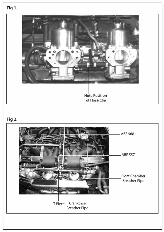
Disconnect Battery terminalsRemove Rain Shields from both banksRemove air cleaner boxes by undoing the 4 bolts on front �ange and removing the clips connecting the warm air pipe and the air inlet horn on each bankDisconnect crankcase breather pipes at Carburetters and remove hose and steel lines across block back to “T” piece on end of pipefrom left hand tappet blockUndo screws on choke cam and disconnect choke cable at clip on both sets of CarburettersRemove vacuum retard pipe on bottom of rear left hand Carburetter, and at distributor and removeUnclip ball socket on both rear CarburettersRemove all 16 nuts and washers attaching Carburetters to manifold, undo fuel line “T” pieces at Carburetter and remove Carburetters there can be a reasonable amount of fuel leftin the fuel supply line so be careful to collect any spillage.Remove manifold spacer gaskets and clean faces of gasket material and carbon deposits.Re�t new manifold spacers with a gasket bothsidesA new ball joint is �tted to the two rear Carburetter to replace the original one if required.Right hand drive manual cars will require clutch master cylinder spacer to be �tted (Partnumber ABF556) to give clearance for right hand rear Carburetter.Loosely assemble a pair of Carburetters (unitsare identi�ed on tag) with linkage rods from kit of parts (it will be necessary to undo clamp bolts when tuning the vehicle but leave leverstight to enable initial starting). Note: It is easier to adjust levers with nuts showing uppermost when �tted. Loosely re-attach fuel line from ‘T’piece to Carburetters using new piece of hose
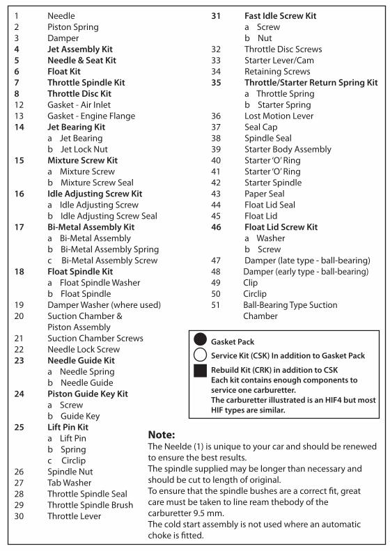
(supplied) and hose clips, ensuringclosure is well away from choke camwhen �tted (See Photo Fig 1.)O�er each pair of units onto manifolds and attach with new nuts and washers supplied. Close fuel line hose clamps using end jaw pincers/pliers.Using rubber pipe supplied attach vacuum from distributor to nipple on right hand rear Carburetter.Using rubber pipe supplied connect the crankcase breather pipes to “T” pieces supplied and then connect to pipe from tappet block via pieces of steel pipe supplied attached to clip on manifold, short pipe (ABF557) on left bank and longpipe (ABF568) on right bank, with short end angled down towards air cleaner as per illustration (Fig 2).Re-attach ball joint on rear units, one at a time, ensuring full throttle is achievable (adjust lever on throttle spindle to change this and adjust ball joint on rod to synchronize each bank).Using 50cm of ¼” bore rubber hose supplied, attach to �oat chamber breather pipes and route down and away from Carburetter ensuring there are no kinks or vapour traps and ensuring line is well clear of exhaust.Re-attach choke cable through ferrule on left hand front and right hand rear units and attach to choke cam via screw, ensuring full and free range of movement available.Use cable ties included to tidy up choke cable, fuel line and breather pipe runs across block.Re�t rain shields.Air cleaners can be re-attached but it will be necessary to shorten threaded end of bolts to 10mm. Re-attach warm air and air inlet hornsRefer to tuning lea�et and vehicle manufacturers’ data for starting and tuning procedure.
14.
15.
16.
17.
18.
19.
20.
21.22.
23.
Before starting, see note on engine/gearbox mounts.
V12 Jaguar Conversion Kit
Fig 1.
Note Position of Hose Clip
Fig 2.
T Piece CrankcaseBreather Pipe
Float ChamberBreather Pipe
ABF 557
ABF 568
Procedure
1.2.3.
4.
5.
6.
7.
8.
9.
10.
11.
12.
13.
Disconnect Battery terminalsRemove Rain Shields from both banksRemove air cleaner boxes by undoing the 4 bolts on front �ange and removing the clips connecting the warm air pipe and the air inlet horn on each bankDisconnect crankcase breather pipes at Carburetters and remove hose and steel lines across block back to “T” piece on end of pipefrom left hand tappet blockUndo screws on choke cam and disconnect choke cable at clip on both sets of CarburettersRemove vacuum retard pipe on bottom of rear left hand Carburetter, and at distributor and removeUnclip ball socket on both rear CarburettersRemove all 16 nuts and washers attaching Carburetters to manifold, undo fuel line “T” pieces at Carburetter and remove Carburetters there can be a reasonable amount of fuel leftin the fuel supply line so be careful to collect any spillage.Remove manifold spacer gaskets and clean faces of gasket material and carbon deposits.Re�t new manifold spacers with a gasket bothsidesA new ball joint is �tted to the two rear Carburetter to replace the original one if required.Right hand drive manual cars will require clutch master cylinder spacer to be �tted (Partnumber ABF556) to give clearance for right hand rear Carburetter.Loosely assemble a pair of Carburetters (unitsare identi�ed on tag) with linkage rods from kit of parts (it will be necessary to undo clamp bolts when tuning the vehicle but leave leverstight to enable initial starting). Note: It is easier to adjust levers with nuts showing uppermost when �tted. Loosely re-attach fuel line from ‘T’piece to Carburetters using new piece of hose
ight
y
ing line is
rule on
ement
eaded end of m air and air
14.
15.
16.
17.
18.
19.
20.
21.22.
23.
Before starting, see note on engine/gearbox mounts.
V12 Jaguar Conversion Kit
Fig 1.
Note Position of Hose Clip
Fig 2.
T Piece CrankcaseBreather Pipe
Float ChamberBreather Pipe
ABF 557
ABF 568

HIF
Typ
e Ca
rbur
ette
r Kit
Copyright © 2009 BFS Technical Services / ALT 1493
Tuning GuideIMPORTANT: Read BeforeCommencing Work
These instructions are intended as a general guide to servicing and tuning the type HIF carburetter in both single and multi-installations. It is essential, particularly where vehicles are equipped and tuned to comply with engine emission control regulations, that the carburetters are tuned in accordance with the vehicle manufacturer’s tuning data.
To achieve the best results when tuning, the use of a reliable tachometer, balancing meter and an exhaust gas analyser are required. These instruments are essential when tuning vehicles equipped to conform with exhaust emission regulations.
Before servicing or tuning a carburetter in an endeavour to rectify poor engine performance, make sure that the maladjustment or fault is not from another source by checking the following:
Valve clearance Spark plug condition Contact breaker (dwell angle) Ignition timing and advance Presence of air leaks into the induction system
This Kit contains only Genuine SU Components
The SU Carburetter CompanySpit�re House, Castle Road, Salisbury, Wiltshire, SP1 3SB
T: 00 44 (0)1722 412 500 | F: 00 44 (0)1722 334 221 | W: www.sucarb.co.uk
ALT 1493

HIF
Typ
e Ca
rbur
ette
r Kit
- A
LT 9
110
Serv
icin
g &
Tun
ing
Gui
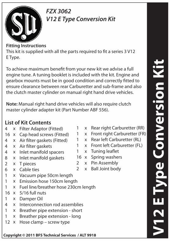
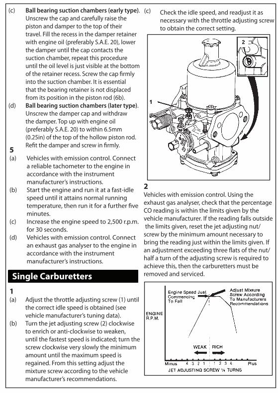
de1 Needle2 Piston Spring3 Damper4 Jet Assembly Kit5 Needle & Seat Kit6 Float Kit7 Throttle Spindle Kit8 Throttle Disc Kit12 Gasket - Air Inlet13 Gasket - Engine Flange14 Jet Bearing Kit a Jet Bearing b Jet Lock Nut15 Mixture Screw Kit a Mixture Screw b Mixture Screw Seal16 Idle Adjusting Screw Kit a Idle Adjusting Screw b Idle Adjusting Screw Seal17 Bi-Metal Assembly Kit a Bi-Metal Assembly b Bi-Metal Assembly Spring c Bi-Metal Assembly Screw18 Float Spindle Kit a Float Spindle Washer b Float Spindle19 Damper Washer (where used)20 Suction Chamber & Piston Assembly21 Suction Chamber Screws22 Needle Lock Screw23 Needle Guide Kit a Needle Spring b Needle Guide24 Piston Guide Key Kit a Screw b Guide Key25 Lift Pin Kit a Lift Pin b Spring c Circlip26 Spindle Nut27 Tab Washer28 Throttle Spindle Seal29 Throttle Spindle Brush30 Throttle Lever
31 Fast Idle Screw Kit a Screw b Nut32 Throttle Disc Screws33 Starter Lever/Cam34 Retaining Screws35 Throttle/Starter Return Spring Kit a Throttle Spring b Starter Spring36 Lost Motion Lever37 Seal Cap38 Spindle Seal39 Starter Body Assembly40 Starter ‘O’ Ring41 Starter ‘O’ Ring42 Starter Spindle43 Paper Seal44 Float Lid Seal45 Float Lid46 Float Lid Screw Kit a Washer b Screw47 Damper (late type - ball-bearing)48 Damper (early type - ball-bearing)49 Clip50 Circlip51 Ball-Bearing Type Suction Chamber
Note:The Neelde (1) is unique to your car and should be renewed to ensure the best results.The spindle supplied may be longer than necessary and should be cut to length of original.To ensure that the spindle bushes are a correct �t, great care must be taken to line ream thebody of the carburetter 9.5 mm.The cold start assembly is not used where an automatic choke is �tted.
Gasket Pack
Service Kit (CSK) In addition to Gasket Pack
Rebuild Kit (CRK) in addition to CSKEach kit contains enough components to service one carburetter.The carburetter illustrated is an HIF4 but most HIF types are similar.
Remove the air cleaner(s).Check the throttle for correct operation and signs of sticking.Unscrew the throttle adjusting screw (each screw on multi-carburetters) until it is clear of the throttle lever with the throttle closed, then turn the screw clockwise 1.5 full turns (single), one turn on each (multi-carburetters) (1).Raise the piston of each carburetter with the lifting pin (2) and check that it falls freely onto the bridge when the pin is released. If the piston shows any tendency to stick, the carburetter must be serviced.
1(a)(b)
(c)
(d)
2(a) Lift and support the piston clear of the
bridge so that the jet is visible; if this is notpossible due to the installed position of the carburetter, remove the suction chamber assembly.
(b)
(c)
(d)
(e)
Turn the jet adjusting nut/screw up/anti-clockwise, until the jet is �ush with the bridge or as high as possible without exceeding the bridge height (3). Ensure that the jets on multi-carburetters are in the same relative position to the bridge of their respective carburetters.Check that the sintered needle guide is �ush with the underside face of thepiston (4).Turn the jet adjusting nut/screw (3) two turns down/clockwise (each nut/screw on multi-carburetters).Turn the fast-idle adjusting screw anti-clockwise (each screw multi-carburetters) until it is well clear of the cam (5).
3Re�t the suction chamber assembly if it has been removed and, using the lifting pin (2), check that the piston falls freely onto the bridge.Note: If ball bearing suction chambers are �tted take care not to wind up the piston spring when re�tting the suction chamber.
4Check the piston damper oil level:
(a) Standard suction chambers. Unscrew the cap and withdraw the damper. Top up with engine oil (preferably S.A.E. 20) until the level is just below the top of the hollow piston rod, re�t the damper andscrew the cap �rmly into the suction chamber (6a).
HIF
Typ
e Ca
rbur
ette
r Kit
- A
LT 9
110
Serv
icin
g &
Tun
ing
Gui
de
1 Needle2 Piston Spring3 Damper4 Jet Assembly Kit5 Needle & Seat Kit6 Float Kit7 Throttle Spindle Kit8 Throttle Disc Kit12 Gasket - Air Inlet13 Gasket - Engine Flange14 Jet Bearing Kit a Jet Bearing b Jet Lock Nut15 Mixture Screw Kit a Mixture Screw b Mixture Screw Seal16 Idle Adjusting Screw Kit a Idle Adjusting Screw b Idle Adjusting Screw Seal17 Bi-Metal Assembly Kit a Bi-Metal Assembly b Bi-Metal Assembly Spring c Bi-Metal Assembly Screw18 Float Spindle Kit a Float Spindle Washer b Float Spindle19 Damper Washer (where used)20 Suction Chamber & Piston Assembly21 Suction Chamber Screws22 Needle Lock Screw23 Needle Guide Kit a Needle Spring b Needle Guide24 Piston Guide Key Kit a Screw b Guide Key25 Lift Pin Kit a Lift Pin b Spring c Circlip26 Spindle Nut27 Tab Washer28 Throttle Spindle Seal29 Throttle Spindle Brush30 Throttle Lever
31 Fast Idle Screw Kit a Screw b Nut32 Throttle Disc Screws33 Starter Lever/Cam34 Retaining Screws35 Throttle/Starter Return Spring Kit a Throttle Spring b Starter Spring36 Lost Motion Lever37 Seal Cap38 Spindle Seal39 Starter Body Assembly40 Starter ‘O’ Ring41 Starter ‘O’ Ring42 Starter Spindle43 Paper Seal44 Float Lid Seal45 Float Lid46 Float Lid Screw Kit a Washer b Screw47 Damper (late type - ball-bearing)48 Damper (early type - ball-bearing)49 Clip50 Circlip51 Ball-Bearing Type Suction Chamber
Note:The Neelde (1) is unique to your car and should be renewed to ensure the best results.The spindle supplied may be longer than necessary and should be cut to length of original.To ensure that the spindle bushes are a correct �t, great care must be taken to line ream thebody of the carburetter 9.5 mm.The cold start assembly is not used where an automatic choke is �tted.
Gasket Pack
Service Kit (CSK) In addition to Gasket Pack
Rebuild Kit (CRK) in addition to CSKEach kit contains enough components to service one carburetter.The carburetter illustrated is an HIF4 but most HIF types are similar.
Remove the air cleaner(s).Check the throttle for correct operation and signs of sticking.Unscrew the throttle adjusting screw (each screw on multi-carburetters) until it is clear of the throttle lever with the throttle closed, then turn the screw clockwise 1.5 full turns (single), one turn on each (multi-carburetters) (1).Raise the piston of each carburetter with the lifting pin (2) and check that it falls freely onto the bridge when the pin is released. If the piston shows any tendency to stick, the carburetter must be serviced.
1(a)(b)
(c)
(d)
2(a) Lift and support the piston clear of the
bridge so that the jet is visible; if this is notpossible due to the installed position of the carburetter, remove the suction chamber assembly.
(b)
(c)
(d)
(e)
Turn the jet adjusting nut/screw up/anti-clockwise, until the jet is �ush with the bridge or as high as possible without exceeding the bridge height (3). Ensure that the jets on multi-carburetters are in the same relative position to the bridge of their respective carburetters.Check that the sintered needle guide is �ush with the underside face of thepiston (4).Turn the jet adjusting nut/screw (3) two turns down/clockwise (each nut/screw on multi-carburetters).Turn the fast-idle adjusting screw anti-clockwise (each screw multi-carburetters) until it is well clear of the cam (5).
3Re�t the suction chamber assembly if it has been removed and, using the lifting pin (2), check that the piston falls freely onto the bridge.Note: If ball bearing suction chambers are �tted take care not to wind up the piston spring when re�tting the suction chamber.
4Check the piston damper oil level:
(a) Standard suction chambers. Unscrew the cap and withdraw the damper. Top up with engine oil (preferably S.A.E. 20) until the level is just below the top of the hollow piston rod, re�t the damper andscrew the cap �rmly into the suction chamber (6a).

HIF Type Carburetter Kit - ALT 9110 Servicing & Tuning Guide
36
Lost
Mot
ion
Leve
r37
Se
al C
ap38
Sp
indl
e Se
al39
St
arte
r Bod
y A
ssem
bly
40
Star
ter ‘
O’ R
ing
41
Star
ter ‘
O’ R
ing
42
Star
ter S
pind
le43
Pa
per S
eal
44
Floa
t Lid
Sea
l45
Fl
oat L
id
46
Floa
t Lid
Scr
ew K
it
a W
ashe
r
b
Scre
w47
D
ampe
r (la
te ty
pe -
ball-
bear
ing)
48
Dam
per (
early
type
- ba
ll-be
arin
g)49
Cl
ip50
Ci
rclip
51
Ball-
Bear
ing
Type
Suc
tion
Ch
ambe
r
Not
e:Th
e N
eeld
e (1
) is
uniq
ue to
you
r car
and
sho
uld
be re
new
ed to
ens
ure
the
best
resu
lts.
The
spin
dle
supp
lied
may
be
long
er th
an n
eces
sary
and
sho
uld
be c
ut to
leng
th o
f orig
inal
.To
ens
ure
that
the
spin
dle
bush
es a
re a
cor
rect
�t,
grea
t car
e m
ust b
e ta
ken
to li
ne re
am th
ebo
dy o
f the
car
bure
tter
9.5
mm
.Th
e co
ld s
tart
ass
embl
y is
not
use
d w
here
an
auto
mat
ic c
hoke
is �
tted
.
Gas
ket P
ack
Serv
ice
Kit (
CSK)
In a
dditi
on to
Gas
ket P
ack
Rebu
ild K
it (C
RK) i
n ad
ditio
n to
CSK
Each
kit
cont
ains
eno
ugh
com
pone
nts
to
serv
ice
one
carb
uret
ter.
The
carb
uret
ter i
llust
rate
d is
an
HIF
4 bu
t mos
t H
IF ty
pes
are
sim
ilar.
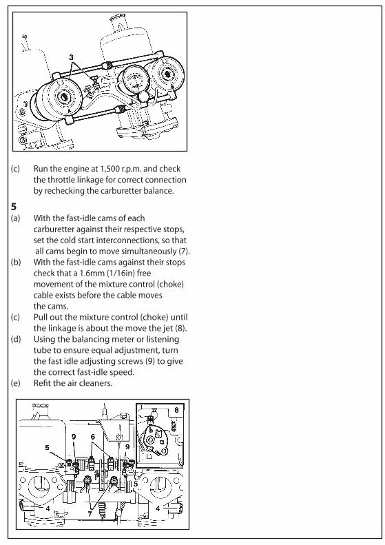
Ball bearing suction chambers (early type).Unscrew the cap and carefully raise the piston and damper to the top of their travel. Fill the recess in the damper retainer with engine oil (preferably S.A.E. 20), lower the damper until the cap contacts the suction chamber, repeat this procedure until the oil level is just visible at the bottom of the retainer recess. Screw the cap �rmly into the suction chamber. It is essential that the bearing retainer is not displaced from its position in the piston rod (6b).Ball bearing suction chambers (later type). Unscrew the damper cap and withdraw the damper. Top up with engine oil (preferably S.A.E. 20) to within 6.5mm (0.25in) of the top of the hollow piston rod. Re�t the damper and screw in �rmly.
(c)
(d)
Vehicles with emission control. Connect a reliable tachometer to the engine in accordance with the instrument manufacturer’s instructions.Start the engine and run it at a fast-idle speed until it attains normal running temperature, then run it for a further �ve minutes.Increase the engine speed to 2,500 r.p.m. for 30 seconds.Vehicles with emission control. Connect an exhaust gas analyser to the engine in accordance with the instrument manufacturer’s instructions.
5(a)
(b)
(c)
(d)
Single Carburetters
Adjust the throttle adjusting screw (1) until the correct idle speed is obtained (see vehicle manufacturer’s tuning data).Turn the jet adjusting screw (2) clockwise to enrich or anti-clockwise to weaken, until the fastest speed is indicated; turn the screw clockwise very slowly the minimum amount until the maximum speed is regained. From this setting adjust the mixture screw according to the vehicle manufacturer’s recommendations.
1(a)
(b)
2Vehicles with emission control. Using the exhaust gas analyser, check that the percentage CO reading is within the limits given by the vehicle manufacturer. If the reading falls outside the limits given, reset the jet adjusting nut/screw by the minimum amount necessary to bring the reading just within the limits given. If an adjustment exceeding three �ats of the nut/half a turn of the adjusting screw is required to achieve this, then the carburetters must be removed and serviced.
Check the idle speed, and readjust it as necessary with the throttle adjusting screw to obtain the correct setting.
(c)
HIF Type Carburetter Kit - ALT 9110 Servicing & Tuning Guide
36
Lost
Mot
ion
Leve
r37
Se
al C
ap38
Sp
indl
e Se
al39
St
arte
r Bod
y A
ssem
bly
40
Star
ter ‘
O’ R
ing
41
Star
ter ‘
O’ R
ing
42
Star
ter S
pind
le43
Pa
per S
eal
44
Floa
t Lid
Sea
l45
Fl
oat L
id
46
Floa
t Lid
Scr
ew K
it
a W
ashe
r
b
Scre
w47
D
ampe
r (la
te ty
pe -
ball-
bear
ing)
48
Dam
per (
early
type
- ba
ll-be
arin
g)49
Cl
ip50
Ci
rclip
51
Ball-
Bear
ing
Type
Suc
tion
Ch
ambe
r
Not
e:Th
e N
eeld
e (1
) is
uniq
ue to
you
r car
and
sho
uld
be re
new
ed to
ens
ure
the
best
resu
lts.
The
spin
dle
supp
lied
may
be
long
er th
an n
eces
sary
and
sho
uld
be c
ut to
leng
th o
f orig
inal
.To
ens
ure
that
the
spin
dle
bush
es a
re a
cor
rect
�t,
grea
t car
e m
ust b
e ta
ken
to li
ne re
am th
ebo
dy o
f the
car
bure
tter
9.5
mm
.Th
e co
ld s
tart
ass
embl
y is
not
use
d w
here
an
auto
mat
ic c
hoke
is �
tted
.
Gas
ket P
ack
Serv
ice
Kit (
CSK)
In a
dditi
on to
Gas
ket P
ack
Rebu
ild K
it (C
RK) i
n ad
ditio
n to
CSK
Each
kit
cont
ains
eno
ugh
com
pone
nts
to
serv
ice
one
carb
uret
ter.
The
carb
uret
ter i
llust
rate
d is
an
HIF
4 bu
t mos
t H
IF ty
pes
are
sim
ilar.
Ball bearing suction chambers (early type).Unscrew the cap and carefully raise the piston and damper to the top of their travel. Fill the recess in the damper retainer with engine oil (preferably S.A.E. 20), lower the damper until the cap contacts the suction chamber, repeat this procedure until the oil level is just visible at the bottom of the retainer recess. Screw the cap �rmly into the suction chamber. It is essential that the bearing retainer is not displaced from its position in the piston rod (6b).Ball bearing suction chambers (later type). Unscrew the damper cap and withdraw the damper. Top up with engine oil (preferably S.A.E. 20) to within 6.5mm (0.25in) of the top of the hollow piston rod. Re�t the damper and screw in �rmly.
(c)
(d)
Vehicles with emission control. Connect a reliable tachometer to the engine in accordance with the instrument manufacturer’s instructions.Start the engine and run it at a fast-idle speed until it attains normal running temperature, then run it for a further �ve minutes.Increase the engine speed to 2,500 r.p.m. for 30 seconds.Vehicles with emission control. Connect an exhaust gas analyser to the engine in accordance with the instrument manufacturer’s instructions.
5(a)
(b)
(c)
(d)
Single Carburetters
Adjust the throttle adjusting screw (1) until the correct idle speed is obtained (see vehicle manufacturer’s tuning data).Turn the jet adjusting screw (2) clockwise to enrich or anti-clockwise to weaken, until the fastest speed is indicated; turn the screw clockwise very slowly the minimum amount until the maximum speed is regained. From this setting adjust the mixture screw according to the vehicle manufacturer’s recommendations.
1(a)
(b)
2Vehicles with emission control. Using the exhaust gas analyser, check that the percentage CO reading is within the limits given by the vehicle manufacturer. If the reading falls outside the limits given, reset the jet adjusting nut/screw by the minimum amount necessary to bring the reading just within the limits given. If an adjustment exceeding three �ats of the nut/half a turn of the adjusting screw is required to achieve this, then the carburetters must be removed and serviced.
Check the idle speed, and readjust it as necessary with the throttle adjusting screw to obtain the correct setting.
(c)

Multi - Carburetters
Slacken both clamping bolts (1) on the throttle spindle interconnections.Slacken both clamping bolts (2) on the cold start interconnections.
1(a)
(b)
2Using a balancing meter in accordance with the maker’s instructions, balance the carburetters byaltering the throttle adjusting screws (3) until the correct idle speed and balance is achieved. Alternatively, use a ‘listening tube’ to compare the intensity of the intake hiss on all carburetters and turn the throttle adjusting screws until the hiss is the same.
Turn the jet adjusting screw (4) on each carburetter clockwise to enrich or anti-clockwise to weaken, by the same amount until the fastest speed is indicated; turn each screw anti-clockwise until the engine speed just commences to fall. Turn each screw very slowly clockwise by the minimum amount until the maximum speed is regained. From this setting adjust the mixture screws according to the vehicle manufacturer’s recommendations. (See graph on previous page).Check the idle speed and readjust it as necessary with the throttle adjusting screws (5), turning each by the same amount.
3(a)
(b)
Vehicles with emission control. Using the exhaust gas analyser, check that the reading is within the limits given in the vehicle manufacturer’s tuning data. If thereading falls outside the limits given, reset both the jet adjusting screws by the minimum amount necessary to bring the readings just within the limits.Set the throttle interconnection clampinglevers (6), in accordance with the vehiclemanufacturer’s instructions, so that a clearance exists between the link pin and the lower edge of the fork. Tighten the clamp bolts, ensuring that there is approximately 0.8mm (1/32in) end-�oat on the interconnection rod.
4(a)
(b)
Run the engine at 1,500 r.p.m. and check the throttle linkage for correct connection by rechecking the carburetter balance.
(c)
With the fast-idle cams of each carburetter against their respective stops, set the cold start interconnections, so that all cams begin to move simultaneously (7).With the fast-idle cams against their stops check that a 1.6mm (1/16in) free movement of the mixture control (choke) cable exists before the cable moves the cams.Pull out the mixture control (choke) until the linkage is about the move the jet (8).Using the balancing meter or listening tube to ensure equal adjustment, turnthe fast idle adjusting screws (9) to give the correct fast-idle speed.Re�t the air cleaners.
5(a)
(b)
(c)
(d)
(e)
With the fast-idle cam against its return stop, check that a 1.6mm (1/16in) free movement of the mixture control (choke) cable exists before the cable moves the cam.Pull out the mixture control (choke) (3) until the linkage is about to move the jet.Turn the fast-idle adjusting screw (4) clockwise until the correct fast-idle speedis obtained (see the vehicle manufacturer’srecommendations).Re�t the air cleaner.
3(a)
(b)
(c)
(d)