Embed Size (px)
Citation preview

E-Z-GO Industrial 640 / Cushman Stock Chaser.... Kit 4139011E-Z-GO Industrial 875 / Cushman Titan .................. Kit 4139014E-Z-GO Industrial 340 / Cushman Tug .................... Kit 4140359
Fitting Instructions for EC Kits
WARNING: If incorrectly used this machine can cause severeinjury. Those who use and maintain this machine should betrained in its proper use, warned of its dangers and shouldread the entire manual before attempting to set up, operate,adjust or service the machine.
24757G-GB (rev.0)


3
FITTING GUIDE
TITAN INDUSTRIAL 875
BATTERY DISCONNECT SWITCH
KIT PART NUMBER
4139014
Component Parts
1 off Push / Pull Switch 4139009
1 off Positive battery Cable 4139015
Existing Circuit

4
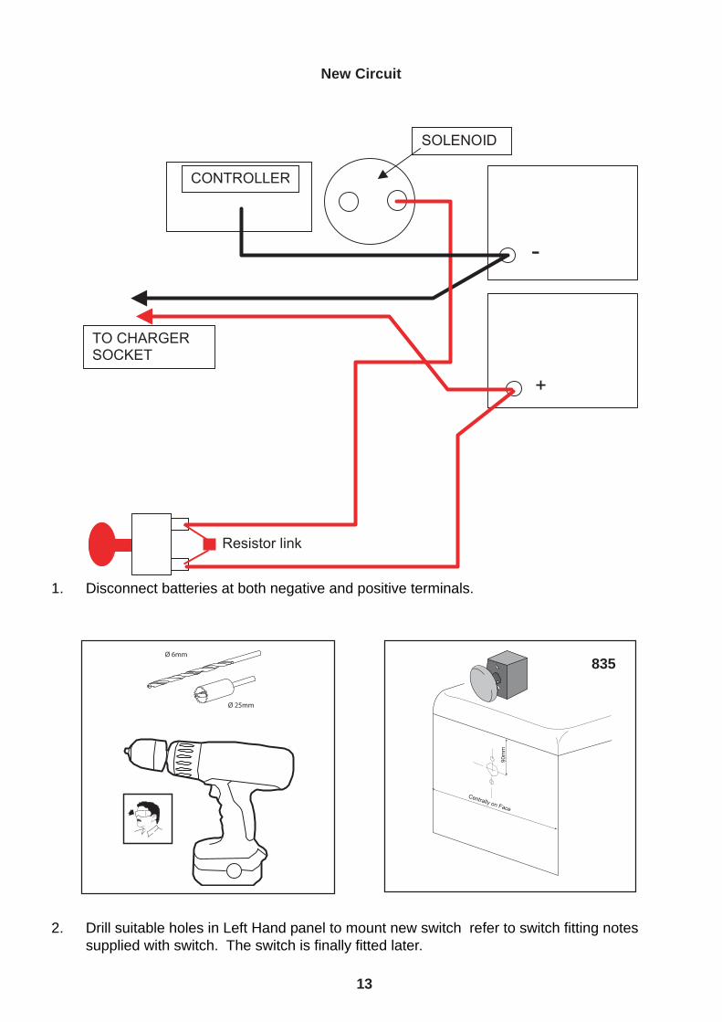
New Circuit
1. Disconnect batteries at both negative and positive terminals.

5
2. Drill suitable holes in Seat panel to mount new switch refer to switch fitting notes supplied withswitch. The switch is finally fitted later.
FIT SWITCH HERE FACING UPWARDS
3. Reroute the cable that was fitted to the Positive battery cable to the new switch.
4. Fit new cable supplied with kit from new switch terminal to the battery Positive Terminal, ensuringthat the fitted resistor is at the switch end. Ensure that the resistor is fitted to both terminalsacross the switch.
5. Route both the new switch cable through the existing cable clips fitted to the central spar of themachine.
6. Connect new cable and charger cable to positive battery terminal.
875

6
7. Ensure all screws are tight on the switch terminals.
8. Slide switch into position and feed up through previously drilled holes, Fit switch into positionpaying particular attention to the knob fitting instruction supplied. Ensure all screws are tight.
9. Push new switch in to ensure circuit is open.
10. Refit battery negative cable and charger cable to negative terminal of battery.
11. Pull new switch knob firmly out to connect circuit.
12. Test machine operation.

7
TITAN / 875 SRO LOOM AND CONTROLLER
SUPPLIED AS KIT WITH ALL COMPONENTS
COMPONENT PARTSCONTROLLER UNIT 4140205 (TWL 010626-00)LOOM 4140206 (TWL 010627-01)LOGIC RELAY (TWL 17-00732)
1. DISCONNECT BATTERY NEGATIVE TERMINAL FROM LEFT HAND REAR BATTERY.
2. Expose controller and wiring by lifting cover panel.
3. Route the new loom into machine following line of existing loom, starting from thecontroller and working forwards, to the steering column. Ensure loom cannot chafe on anysharp edges.
4. Route Black wire through side chassis rail to area of battery negative
5. Route seat switch wires over chassis side rail to underside of seat switch.
6. Disconnect existing blue wire and connect to new blue wire.
7. Connect new blue/orange wire to seat switch. You should now have old orange wire andnew blue/orange wires connecte to the seat switch.
8. Disconnect the existing plastic connector to the throttle pedal from the existing loom.
9. Connect the new 4 way connector to bridge the original 4 way connectors.
10. Route the orange and green wires to the rear of the direction switch.
11. Remove the existing Orange wire from the direction switch, fit the new orange wire in it’splace. Fit the original orange wire into the tail of the new connector.

8
12. Repeat 11. for the green wire.
13. Repeat 11. for the grey wire. The grey wire must be in the middle.
14. Remove the yellow wire from the rear of the logic switch and connect to the short yellowwire from the new Logic Relay.
15. Connect the Long yellow wire from the logic relay to the vacant position on the rear of theLogic switch.
16. Check the loom fits naturally and using tyraps hold to the original loom.
POSITION NEW RELAY AND CONTROLLER HERELOGIC SWITCH
17. Fit the blue and white wire to the vacant position on the fuse box, located behind thecontroller, fit 2amp fuse to the same position. Ensure there is 12V at the wire connection.(Use a DVM for this)
17. Refit Controller cover.

9
SRO Wiring Diagram
18. Connect new ground terminal and refit existing ground terminals to battery.
19. Testing the new SRO System
a. Sit on seat, select FWD, press Throttle gently and whilst moving forward lift weght from theseat.
i. The machine will STOP.ii. Resit on seat and attempt to drive forward, Nothing will happen.1. Release Throttle pedal, select neutral with direction switch, wait 1 second, re-select
forward, re-apply throttle the machine will move.
b. The same rule applies in Reverse.
IT IS STRONGLY RECOMMENDED THAT IF THE MACHINE IS TO BE LEFT STORED FORANY LENGTH OF TIME THAT THE BATTERIES ARE DISCONNECTED AT BOTH POSITIVEAND NEGATIVE POSTS.

10

11
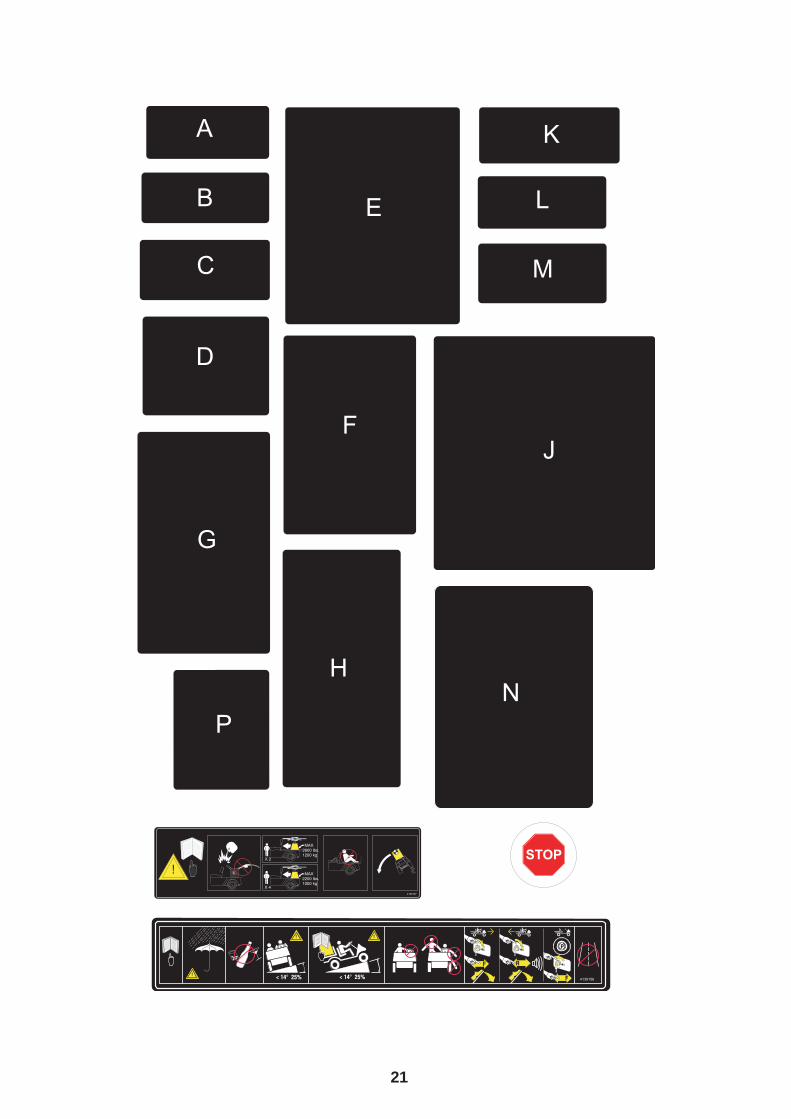
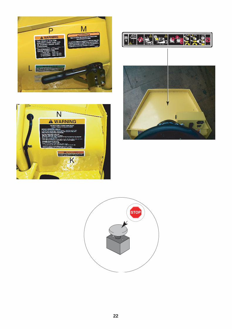
All worded decals must be covered with the blanks provided
INDUSTRIAL XI875
12
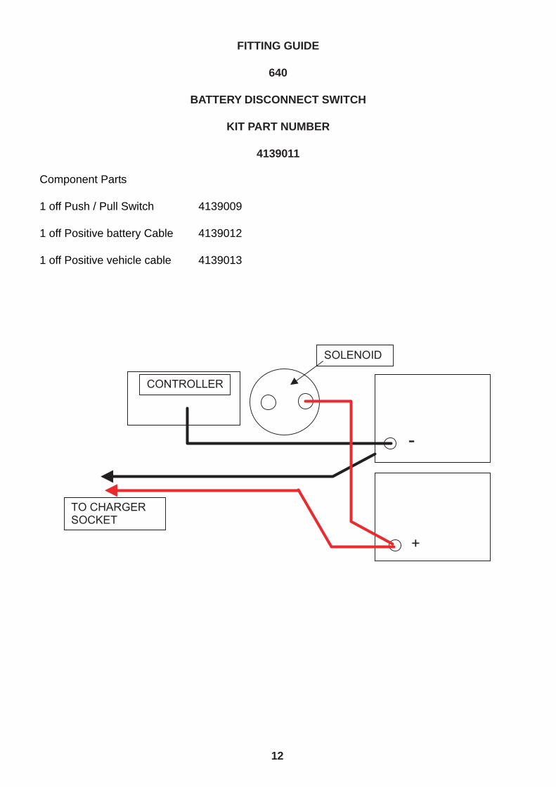
FITTING GUIDE
640
BATTERY DISCONNECT SWITCH
KIT PART NUMBER
4139011
Component Parts
1 off Push / Pull Switch 4139009
1 off Positive battery Cable 4139012
1 off Positive vehicle cable 4139013
13
New Circuit
1. Disconnect batteries at both negative and positive terminals.
2. Drill suitable holes in Left Hand panel to mount new switch refer to switch fitting notessupplied with switch. The switch is finally fitted later.
835

14
3. Remove the cover that is over the motor controller and solenoid.
4. Remove and discard old positive cable from battery to solenoid. This is no longer required
5. Fit new cable supplied with kit from a new switch terminal to the solenoid, ensuring that thefitted resistor is at the switch end from the solenoid. Make sure that all terminals arerefitted to the solenoid.

6. Fit 2nd new cable from the switch to the positive battery terminal, ensure that the resistor isfitted to both terminals across the switch.
7. Route both the new switch cable through the existing cable clips fitted to the central spar ofthe machine.
8. Connect new cable and charger cable to positive battery terminal.
9. Ensure all screws are tight on the switch terminals.
10. Slide switch into position and feed up through previously drilled holes, Fit switch intoposition paying particular attention to the knob fitting instruction supplied. Ensure allscrews are tight.
11. Push new switch in to ensure circuit is open.
12. Refit battery negative cable and charger cable to negative terminal of battery.
13. Pull new switch knob firmly out to connect circuit.
14. Test machine operation.

16

17
All worded decals must be covered with the blanks provided
INDUSTRIAL XI640

18
FITTING GUIDE
TUG
BATTERY DISCONNECT SWITCH
KIT PART NUMBER
BATTERIES
Component Parts
1 off Push / Pull Switch 4139009
1 off Positive battery Cable 010559-00
6 off Positive Terminal Covers 4139551
6 off Negative Terminal Covers 4139550
Existing Circuit

19
BATTERIES
1. Disconnect batteries at both negative and positive terminals.
New Circuit
2. Drill suitable holes in panel below the seat panel to mount new switch refer to switch fitting notessupplied with switch. (see picture 1) Fit switch following instructions supplied, with particularattention to knob installation.

20
3. Route positive (RED) cable that was on positive terminal to one side of new switch. Fit withsupplied screw and washers. (See picture 2)
4. Fit new cable supplied with kit to 2nd switch terminal, with resistor ring terminal connected toterminal with vehicle cable.
5. Disconnect all battery terminals in order and fit supplied terminal covers to cables. Refit andtighten all terminals
6. Connect new cable and charger cable to positive battery terminal.
7. Ensure all screws are tight.
8. Push new switch in to ensure circuit is open.
9. Refit battery negative cable and charger cable to negative terminal of battery.
10. Pull new switch knob firmly out to connect circuit.
11. Test machine operation.
21
22


Ransomes Jacobsen LimitedWest Road, Ransomes Europark, Ipswich, IP3 9TTEnglish Company Registration No. 1070731www.ransomesjacobsen.com