Embed Size (px)
Citation preview

R&G Racing
Unit 1, Shelley’s Lane, East Worldham, Alton, Hampshire, GU34 3AQ
Tel: +44 (0)1420 89007 Fax: +44 (0)1420 87301 www.rg-racing.com Email: [email protected]
Page | 1
FITTING INSTRUCTIONS FOR CP0228BL CRASH PROTECTORS
HONDA CBR1000RR FIREBLADE 2008-
PICTURE ‘A’ 2008-11 MODEL PICTURE ‘B’ 2008-11 MODEL
PICTURE ‘C’ ’12-‘16 MODEL PICTURE ‘D’ ’12-16 MODEL
PICTURE ‘E’ ’17- MODEL PICTURE ‘F’ ’17- MODEL
R&G Racing
Unit 1, Shelley’s Lane, East Worldham, Alton, Hampshire, GU34 3AQ
Tel: +44 (0)1420 89007 Fax: +44 (0)1420 87301 www.rg-racing.com Email: [email protected]
Page | 2
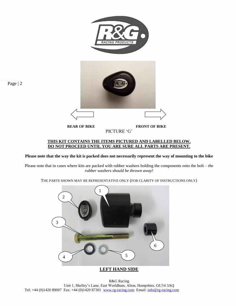
REAR OF BIKE FRONT OF BIKE
PICTURE ‘G’
THIS KIT CONTAINS THE ITEMS PICTURED AND LABELLED BELOW.
DO NOT PROCEED UNTIL YOU ARE SURE ALL PARTS ARE PRESENT.
Please note that the way the kit is packed does not necessarily represent the way of mounting to the bike
Please note that in cases where kits are packed with rubber washers holding the components onto the bolt – the
rubber washers should be thrown away!
THE PARTS SHOWN MAY BE REPRESENTATIVE ONLY (FOR CLARITY OF INSTRUCTIONS ONLY)
LEFT HAND SIDE
1
2
3
4 5
6

R&G Racing
Unit 1, Shelley’s Lane, East Worldham, Alton, Hampshire, GU34 3AQ
Tel: +44 (0)1420 89007 Fax: +44 (0)1420 87301 www.rg-racing.com Email: [email protected]
Page | 3
MARKING TOOL
RIGHT HAND SIDE
TOOLS REQUIRED
Socket set to include 17mm and 19mm sockets and wrench.
Set of metric Allen keys 3, 4 and 5mm A/F.
Phillips screwdriver.
Torque wrench (up to 40Nm).
Drill.
28mm Hole-saw and/or dremmel type tool.
4
5
9
2
8
1
7

R&G Racing
Unit 1, Shelley’s Lane, East Worldham, Alton, Hampshire, GU34 3AQ
Tel: +44 (0)1420 89007 Fax: +44 (0)1420 87301 www.rg-racing.com Email: [email protected]
Page | 4
LEGEND ITEM 1 = B0431 with CS340 (12mm) (BOTH CRASH PROTECTORS) (x2).
ITEM 2 = BC0002 CRASH PROTECTOR CAPS (x2).
ITEM 3 = M12x1.25x100mm LONG HEX HEAD BOLT (x1).
ITEM 4 = M12 PLAIN WASHERS (x2).
ITEM 5 = LW0001 (M12 SHAKE PROOF WASHERS) (x2).
ITEM 6 = S0277 (LEFT HAND SIDE SPACER 18mm LONG) (x1).
ITEM 7 = T0012 MARKING TOOL (75MM LONG M12) (x1).
ITEM 8 = M12x1.25x110mm LONG HEX HEAD BOLT (x1).
ITEM 9 = S0242 (RIGHT HAND SIDE SPACER 15mm LONG) (x1).
To fit to the ’08-’11 & ’12 – ’16 models
PICTURE 1 PICTURE 2
PICTURE 3
Near side (left side as you sit on bike) Undo and remove side fairing screws (on the 2012 model remove the screw in position shown in pictures 1 and 2 then unclip
the lower fairing locations).
Gently support and ease fairing away from bike so a socket and wrench can be used to remove main engine bolt positioned as
shown by bobbin positions and arrows on pictures A and C above (ensure frame/engine spacer stays in position).
Insert pointed/threaded tool (included in kit) into engine mount (with approximately 25mm protruding as shown in picture 3)
so when fairing is placed in position the point just comes into contact with inner face of fairing.

R&G Racing
Unit 1, Shelley’s Lane, East Worldham, Alton, Hampshire, GU34 3AQ
Tel: +44 (0)1420 89007 Fax: +44 (0)1420 87301 www.rg-racing.com Email: [email protected]
Page | 5
Tighten fairing screws and gently knock fairing until dimple is evident on fairing (care must be taken not to damage fairing).
Place masking tape over dimple (to help prevent drill slipping).
Again gently support and ease fairing away from bike and very carefully drill pilot hole for 28mm hole saw (only drill pilot
hole).
Reposition fairing so you can look through pilot hole, you should see the point of the marking tool central to the hole just
drilled.
If happy with position of pilot hole, remove fairing screws and gently support and ease fairing away from bike, remove
marking tool (keep for use on other side).
Carefully open hole with 28mm hole-saw (on the 2012 model you will have to drill through the side fairing and the fairing
trim care must be taken when drilling or a dremmel type tool may be used to remove the corner of the fairing trim).
Deburr hole using a sharp knife or emery paper taking care not to mark outside of fairing and ensure the spacer
and crash protector spigot fit through hole.
Refit the fairing. Take shorter new engine bolt (M12 x 100mm long), place a flat washer up to head of bolt followed by a shake proof washer.
Fit bolt and washer through bobbin (so head of bolt goes into counter bore).
Place the longer spacer over exposed end of bolt up against the crash protector.
Offer the assembly through fairing hole just drilled and tighten slowly ensuring the assembly does not foul or snag on the
fairing. PLEASE NOTE THE CRASH PROTECTOR SHOULD BE POSITIONED AS SHOWN IN PICTURE ‘E’.
Tighten bolt until you feel some compression from inside the protector. Turn a little more so that you feel the compression
increase slightly. Then apply a quarter turn. Do not overtighten as damage can occur to the bike. Do not exceed 40nm of
torque.
When the protector is tight insert the cap.
Off side (right side as you sit on bike) Undo and remove side fairing screws (on the 2012 model remove the screw in position shown in pictures 1 and 2 then unclip
the lower fairing locations).
Gently support and ease fairing away from bike so a socket and wrench can be used to remove main engine bolt positioned as
shown by bobbin positions and arrows on pictures B and D above (ensure frame/engine spacer stays in position).
Insert pointed/threaded tool (included in kit) into engine mount (with approximately 25mm protruding as shown in picture 3)
so when fairing is placed in position the point just comes into contact with inner face of fairing.
Tighten fairing screws and gently knock fairing until dimple is evident on fairing (care must be taken not to damage fairing).
Place masking tape over dimple (to help prevent drill slipping).
Again gently support and ease fairing away from bike and very carefully drill pilot hole for 28mm hole saw (only drill pilot
hole).
Reposition fairing so you can look through pilot hole, you should see the point of the marking tool central to the hole just
drilled.
If happy with position of pilot hole, remove fairing screws and gently support and ease fairing away from bike, remove
marking tool.
Carefully open hole with 28mm hole-saw (on the 2012 model you will have to drill through the side fairing and the fairing
trim care must be taken when drilling or a dremmel type tool may be used to remove the corner of the fairing trim).
Deburr hole using a sharp knife or emery paper taking care not to mark outside of fairing and ensure the spacer
and crash protector spigot fit through hole.
Refit the fairing. Take shorter new engine bolt (M12 x 110mm long), place a flat washer up to head of bolt followed by a shake proof washer.
Fit bolt and washer through bobbin (so head of bolt goes into counter bore).
Place the shorter spacer over exposed end of bolt up against the crash protector.
Offer the assembly through fairing hole just drilled and tighten slowly ensuring the assembly does not foul or snag on the
fairing. PLEASE NOTE THE CRASH PROTECTOR SHOULD BE POSITIONED AS SHOWN IN PICTURE ‘E’.
Tighten bolt until you feel some compression from inside the protector. Turn a little more so that you feel the compression
increase slightly. Then apply a quarter turn. Do not overtighten as damage can occur to the bike. Do not exceed 40nm of
torque.
When the protector is tight insert the cap.

R&G Racing
Unit 1, Shelley’s Lane, East Worldham, Alton, Hampshire, GU34 3AQ
Tel: +44 (0)1420 89007 Fax: +44 (0)1420 87301 www.rg-racing.com Email: [email protected]
Page | 6
To fit to the ’17- models
Picture 4 Picture 5
Picture 6 Picture 7
Picture 8 Picture 9

R&G Racing
Unit 1, Shelley’s Lane, East Worldham, Alton, Hampshire, GU34 3AQ
Tel: +44 (0)1420 89007 Fax: +44 (0)1420 87301 www.rg-racing.com Email: [email protected]
Page | 7
Picture 10 Picture 11
Picture 12 Picture 13
Picture 14 Picture 15

R&G Racing
Unit 1, Shelley’s Lane, East Worldham, Alton, Hampshire, GU34 3AQ
Tel: +44 (0)1420 89007 Fax: +44 (0)1420 87301 www.rg-racing.com Email: [email protected]
Page | 8
Picture 16 Picture 17
Picture 18 Picture 19
Picture 20 Picture 21

R&G Racing
Unit 1, Shelley’s Lane, East Worldham, Alton, Hampshire, GU34 3AQ
Tel: +44 (0)1420 89007 Fax: +44 (0)1420 87301 www.rg-racing.com Email: [email protected]
Page | 9
Near side (left side as you sit on bike) To fit the crash protectors and drill the fairings, the fairings must first be removed from the motorcycle.
To do this, start by removing the plastic panel under the nose of the bike by removing the four plastic fasteners
with a Phillips screwdriver, as arrowed in pictures 4 & 5.
Remove this plastic panel from the motorcycle.
To remove the left side fairing, start by removing the push/pull rivet that secures the inside black plastic in place
in the area around the top of the radiator, as arrowed in picture 6. Simply pull the rivet head to remove the rivet.
Remove the three bolts that secure the lower edge of the fairing to the bellypan, as shown in picture 7.
Remove the two bolts that secure the top edge of the fairing to the nose, as shown in picture 8.
Remove the bolt that secures the fairing to the black plastic that covers the intake tunnel, as shown in picture 9.
The fairing can now be removed. Gently unclip the lower corner of the side fairing from the front of the bellypan
and work your way along the edge, unclipping the fairing tabs from the slots in the bellypan as you go along, as
shown in picture 10.
At the top rear corner of the fairing, where it meets the frame, there is a plastic prong that fits into a rubber
mount that needs to be lifted upward to release, as shown in picture 11.
With this out, the fairing should be free to slide forward and out to remove from the motorcycle, as shown in
picture 12. Picture 13 shows the final plastic mounting points on top of the intake tunnels that the fairing needs
to be removed from and the inner radiator cowling plastic will come away with the fairing.
Remove the engine bolt and insert the marking tool (item 7 – T0012) into the boss so that the point on the end
sits roughly against where the fairing panel sits when refitted to the motorcycle, as shown in picture 14.
Re-fit the fairing panel to the motorcycle and gently press the inner black panel in towards the marking tool to
leave an impression on the panel. Remove the fairing from the motorcycle and there will be a mark on the inside,
as shown in picture 15.
Remove the black plastic panel from the main fairing by removing the two plastic fasteners, as arrowed in
picture 16.
Using a 28mm holesaw cutter, very carefully drill a pilot hole on the marked point (only drill pilot hole).
Re-fit the black panel to the fairing and refit to the motorcycle, ensuring that the marking tool is positioned
within the centre of the drilled hole. Once happy, remove once again from the bike and remove the black panel
from the main fairing.
From the outside surface, carefully open the hole using the 28mm hole saw cutter, as shown in picture 18. This
will break through a rib on the inner surface. Debur the hole using a sharp knife or emery paper taking care not
to mark the outside of the fairing.
Re-fit the inner black panel to the main fairing using the two fasteners and re-fit the fairing to the motorcycle as
shown in picture 19.
The hole in the black panel should now align with the bolt hole. To remove the material from the main fairing
panel, mark on a semi-circle using a marker pen and align with the existing hole. Use a dremel type tool (do not
use a hole saw as the centre cannot be located as it’s on the edge of the panel) to remove the remaining material
(this can either be done on or off the motorcycle).
Remove the marking tool.
Ensure the fairing is correctly positioned on all its mounting points before following the reverse procedure of
removal to re-fit all the mounting bolts.
Take the shorter engine bolt (M12 x 100mm long), place a flat washer up to the head of the bolt followed by a
shake proof washer. Fit the bolt and the washer through the bobbin (so the head of the bolt goes into the counter
bore).
Place the longer spacer over the exposed end of the bolt and up against the crash protector.
Offer the assembly through the fairing hole just drilled and tighten slowly ensuring the assembly does not foul or
snag on the fairing. PLEASE NOTE THE CRASH PROTECTOR SHOULD BE POSITIONED AS
SHOWN IN PICTURE ‘F’.

R&G Racing
Unit 1, Shelley’s Lane, East Worldham, Alton, Hampshire, GU34 3AQ
Tel: +44 (0)1420 89007 Fax: +44 (0)1420 87301 www.rg-racing.com Email: [email protected]
Page | 10
Tighten the crash protector bolt until you feel some compression from inside the protector using a 19mm socket
and wrench. PLEASE NOTE THE CRASH PROTECTOR MUST BE POSITIONED AS IN PICTURE
‘G’ WITH BIGGER END TOWARD FRONT OF BIKE. Turn a little more so that you feel the compression
increase slightly. Then apply a quarter turn. Do not over tighten as damage can occur to the bike. Do not
exceed 40N/m of torque.
Off side (right side as you sit on bike) To remove the right side fairing, follow the same procedure as used on the removal of the left side.
Start by removing the push/pull rivet that secures the inside black plastic in place in the area around the top of
the radiator. Simply pull the rivet head to remove the rivet.
Remove the three bolts that secure the lower edge of the fairing to the bellypan,
Remove the two bolts that secure the top edge of the fairing to the nose.
Remove the bolt that secures the fairing to the black plastic that covers the intake tunnel.
The fairing can now be removed. Gently unclip the lower corner of the side fairing from the front of the bellypan
and work your way along the edge, unclipping the fairing tabs from the slots in the bellypan as you go along.
At the top rear corner of the fairing, where it meets the frame, there is a plastic prong that fits into a rubber
mount that needs to be lifted upward to release.
With this out, the fairing should be free to slide forward and out to remove from the motorcycle.
Remove the engine bolt and insert the marking tool (item 7 – T0012) into this boss so that the point on the end
sits roughly against where the fairing panel sits when refitted to the motorcycle. There is a spacer between the
engine and frame which may drop. This needs to be kept in place when fitting the marking tool/bolt.
Re-fit the fairing panel to the motorcycle and gently press the inner black panel in towards the marking tool to
leave an impression on the panel. Remove the fairing from the motorcycle and there will be a mark on the inside.
Remove the black plastic panel from the main fairing by removing the two plastic fasteners.
Using a 28mm holesaw cutter very carefully drill a pilot hole on the marked point (only drill pilot hole).
Re-fit the black panel to the fairing and refit to the motorcycle, ensuring that the marking tool is positioned
within the centre of the drilled hole. Once happy, remove once again from the bike and remove the black panel
form the main fairing.
From the outside surface, carefully open the hole using the 28mm hole saw cutter. This will break through a rib
on the inner surface. Debur the hole using a sharp knife or emery paper taking care not to mark outside of the
fairing.
Re-fit the inner black panel to the main fairing using the two fasteners and re-fit the fairing to the motorcycle.
The hole in the black panel should now align with the bolt hole. To remove the material from the main fairing
panel, mark on a semi-circle using a marker pen and align with the existing hole. Use a dremel type tool (do not
use a hole saw as the centre cannot be located as it’s on the edge of the panel) to remove the remaining material
(this can either be done on or off the motorcycle).
Remove the marking tool.
Ensure the fairing is correctly positioned on all its mounting points before following the reverse procedure of
removal to re-fit all the mounting bolts.
Re-fit the black plastic panel that fits on the underside of the nose using the four original fasteners.
Take the longer engine bolt (M12 x 110mm long), place a flat washer up to the head of the bolt followed by a
shake proof washer. Fit the bolt and the washer through the bobbin (so the head of the bolt goes into the counter
bore).
Place the shorter spacer over the exposed end of the bolt and up against the crash protector.
Offer the assembly through the fairing hole just drilled and tighten slowly ensuring the assembly does not foul or
snag on the fairing. PLEASE NOTE THE CRASH PROTECTOR SHOULD BE POSITIONED AS
SHOWN IN PICTURE ‘E’.

R&G Racing
Unit 1, Shelley’s Lane, East Worldham, Alton, Hampshire, GU34 3AQ
Tel: +44 (0)1420 89007 Fax: +44 (0)1420 87301 www.rg-racing.com Email: [email protected]
Page | 11
Tighten the crash protector bolt until you feel some compression from inside the protector using a 19mm socket
and wrench. PLEASE NOTE THE CRASH PROTECTOR MUST BE POSITIONED AS IN PICTURE
‘G’ WITH BIGGER END TOWARD FRONT OF BIKE. Turn a little more so that you feel the compression
increase slightly. Then apply a quarter turn. Do not over tighten as damage can occur to the bike. Do not
exceed 40N/m of torque.
If not already fitted fit bubble stickers into recess of both crash protector caps.
Fit crash protector caps into both crash protectors.
ISSUE 3 02/03/2017 (AR)
CONSUMER NOTICE
The catalogue description and any exhibition of samples are only broad indications of the Products and R&G may make design changes which do not
diminish their performance or visual appeal and supplying them in such state shall conform to the order. The Buyer acknowledges no representation or
warranty (other than as to title) has been given or will apply to the Products other than those in R&G’s order or confirmation and the Buyer confirms it has chosen the Products as being of merchantable quality and suitable for its particular purposes. Where R&G fits the Products or undertakes other
services it shall exercise reasonable skill and care and rectify any fault free of charge unless the workmanship has been disturbed. The Buyer is
responsible for ensuring that the warranty on the motorcycle is not affected by the fitting of the Products. On return of any defective Products R&G shall at its option either supply a replacement or refund the purchase money but shall not be liable if the Products have been modified or used or
maintained otherwise than in accordance with R&G’s or manufacturer’s instructions and good engineering practice or if the defect arises from accident
or neglect. Other than identified above and subject to R&G not limiting its liability for causing death and personal injury, it shall not be liable for indirect or consequential loss and otherwise its liability shall be limited to the amounts paid by the Buyer for the Products or the fitting or service
concerned. These terms do not affect the Buyer’s statutory rights.
R&G RACING RETURNS POLICY (NON-FAULTY GOODS)
Returns must be pre-authorised (if not pre-authorised the return will be rejected). Goods may only be returned direct to us if they were purchased direct from us (customer must prove if necessary). Otherwise to be returned to original vendor. Goods must be in re-sellable condition, in the opinion of R&G
Racing. All returns are subject to a 25% restocking and handling fee (25% of the gross value exc. P&P – at the prevailing price at time of purchase). The
customer must pay any and all carriage charges. No returns of discontinued products, unless within 14 days of purchase. This policy does not affect your statutory rights and does not refer to faulty goods.

R&G Racing
Unit 1, Shelley’s Lane, East Worldham, Alton, Hampshire, GU34 3AQ
Tel: +44 (0)1420 89007 Fax: +44 (0)1420 87301 www.rg-racing.com Email: [email protected]
Page | 12
NOTICE DE MONTAGE POUR CP0228BL PROTECTIONS CRASH
HONDA CBR1000RR FIREBLADE 2008-
PHOTO ‘A’ 2008-11 MODÈLE PHOTO ‘B’ 2008-11 MODÈLE
PHOTO ‘C’ ’12-‘16 MODÈLE PHOTO ‘D’ ’12-16 MODÈLE
PHOTO ‘E’ ’17- MODÈLE PHOTO ‘F’ ’17- MODÈLE

R&G Racing
Unit 1, Shelley’s Lane, East Worldham, Alton, Hampshire, GU34 3AQ
Tel: +44 (0)1420 89007 Fax: +44 (0)1420 87301 www.rg-racing.com Email: [email protected]
Page | 13
ARRIÈRE MOTO AVANT MOTO
PHOTO ‘C’
LE KIT CONTIENT LES ARTICLES EXPOSES CI-DESSOUS, VERIFIER QUE TOUTES LES PIECES SOIENT PRESENTES
AVANT DE PROCEDER AU MONTAGE.
LA FAÇON DONT LE KIT EST EMBALLE NE CORRESPOND PAS FORCEMENT A LA FAÇON DE MONTER
LES PIECES SUR LA MOTO.
Notez que si les kits sont emballés avec des rondelles en caoutchouc servant à tenir les composants,
ces rondelles doivent être jetées!
LES PARTIES PRESENTEES PEUVENT ETRE UNIQUEMENT REPRESENTATIVES (POUR LA CLARTE DES
INSTRUCTIONS UNIQUEMENT)
COTÉ GAUCHE
1
2
3
4
5 6

R&G Racing
Unit 1, Shelley’s Lane, East Worldham, Alton, Hampshire, GU34 3AQ
Tel: +44 (0)1420 89007 Fax: +44 (0)1420 87301 www.rg-racing.com Email: [email protected]
Page | 14
OUTIL DE MARQUAGE
COTÉ DROIT
OUTILS REQUIS
Clé à cliquet + douille 17 et 19mm
Clés Allen 3, 4 et 5mm.
Tournevis cruciforme.
Clé dynamométrique (à 40Nm)
Perceuse
Scie trou 28mm et outil dremel.
4
5
9
2
8
1
7

R&G Racing
Unit 1, Shelley’s Lane, East Worldham, Alton, Hampshire, GU34 3AQ
Tel: +44 (0)1420 89007 Fax: +44 (0)1420 87301 www.rg-racing.com Email: [email protected]
Page | 15
LEGENDE
ARTICLE 1 = B0431 avec CS340 (12mm) (LES 2 PROTECTIONS CRASH ) (x2).
ARTICLE 2 = BC0002 CAPUCHONS DE PROTECTION CRASH (x2).
ARTICLE 3 = M12x1.25x100mm BOULON (x1).
ARTICLE 4 = M12 RONDELLES (x2).
ARTICLE 5 = LW0001 (M12 RONDELLES ANTI VIBRATION) (x2).
ARTICLE 6 = S0277 (ENTRETOISE COTE GAUCHE 18mm) (x1).
ARTICLE 7 = T0012 OUTIL DE MARQUAGE (75mm M12) (x1).
ARTICLE 8 = M12x1.25x110mm BOULON (x1).
ARTICLE 9 = S0242 (ENTRETOISE COTE DROIT 15mm DE LONG) (x1).
Installation sur les modèles ’08-’11 & ’12 – ’16
PHOTO 1 PHOTO 2
PHOTO 3
Coté gauche (assis sur la moto)
Enlever les vis de carénages latéraux (Sur le modèle 2012, enlever la vis en position sur les photos 1 et 2 puis déclipser les fixations de carénage inférieur).
Supporter le carénage en l’enlevant de la moto de façon à ce qu’une clé à cliquet + douille puisse être utilisée pour enlever le boulon moteur principal positionné comme indiqué par les positions de la bobine et comme vous pouvez le voir sur les photos A et C ci-dessus (Veiller à ce que l’entretoise cadre/moteur reste en position).

R&G Racing
Unit 1, Shelley’s Lane, East Worldham, Alton, Hampshire, GU34 3AQ
Tel: +44 (0)1420 89007 Fax: +44 (0)1420 87301 www.rg-racing.com Email: [email protected]
Page | 16
Insérer l’outil pointé/fileté (inclus dans le kit) dans le support moteur (avec environ 25mm dépassant, comme indiqués sur la photo 3) de façon à ce que la carénage soit placé dans la position dont le point entre en contact avec la face interne du carénage.
Serrer les vis de carénage puis tapoter le carénage jusqu’à ce que la marque soit évidente sur le carénage (attention à ne pas abimer le carénage).
Placez le ruban adhésif sur les fossettes (Pour empêcher le glissement de la perceuse).
Une nouvelle fois, supporter le carénage en l’enlevant de la moto et percer un trou pilote de 28mm (Percer uniquement le trou pilote).
Repositionner le carénage de façon à ce que vous puissiez voir dans le trou pilote, vous devriez voir le point réalisé avec l’outil de marquage au centre, sur le trou tout juste percé.
Si la position du trou pilote vous convient, enlever les vis de carénage puis supporter le carénage tout en l’enlevant de la moto, avant d’enlever l’outil de marquage (Conservez le pour l’utiliser de l’autre coté).
Ouvrir le trou à l’aide d’une scie trou de 28mm (sur le modèle 2012, vous devrez percer à travers le carénage latéral et la garniture de carénage. Il faut faire très attention lors du perçage ou un outil de type dremel peut être utilisé pour enlever le coin de garniture de carénage).
Ebavurer le trou à l’aide d’un knife bien aiguisé ou du papier Emery, en veillant à ne pas marquer l’extérieur du carénage et en veillant à ce que l’entretoise et le ressort de protection crash se place dans le trou.
Remonter le carénage
Prendre le boulon moteur le plus court (M12 x 100mm de long), placer une rondelle plate sur la tête du boulon suivie d’une rondelle anti vibration. Insérer le boulon et la rondelle dans la bobine (de façon à ce que la tête du boulon se place dans le contre alésage).
Placer la plus longue entretoise sur l’extrémité du boulon et contre la protection crash.
Monter l’ensemble dans le trou de carénage tout juste percé puis serrer doucement en veillant à ce que l’ensemble n’accroche pas le carénage. LA PROTECTION DOIT ETRE POSITIONNEE COMME EN “E”.
Serrer le boulon de la protection crash jusqu’à ce que vous sentiez une légère compression de l’intérieur de la protection. Tourner un peu plus afin d’accentuer légèrement la compression. Appliquer un quart de tour Serrer à 40Nm de couple (ne pas excéder cette valeur, car cela pourrait endommager la moto et le boulon).
Lorsque la protection est serrée, insérer un capuchon. Coté droit (assis sur la moto)
Enlever les vis de carénages latéraux (Sur le modèle 2012, enlever la vis en position sur les photos 1 et 2 puis déclipser les fixations de carénage inférieur).
Supporter le carénage en l’enlevant de la moto de façon à ce qu’une clé à cliquet + douille puisse être utilisée pour enlever le boulon moteur principal positionné comme indiqué par les positions de la bobine et comme vous pouvez le voir sur les photos B et D ci-dessus (Veiller à ce que l’entretoise cadre/moteur reste en position).
Insérer l’outil pointé/fileté (inclus dans le kit) dans le support moteur (avec environ 25mm dépassant, comme indiqués sur la photo 3) de façon à ce que la carénage soit placé dans la position dont le point entre en contact avec la face interne du carénage.
Serrer les vis de carénage puis tapoter le carénage jusqu’à ce que la marque soit évidente sur le carénage (attention à ne pas abimer le carénage).
Placez le ruban adhésif sur les fossettes (Pour empêcher le glissement de la perceuse).
Une nouvelle fois, supporter le carénage en l’enlevant de la moto et percer un trou pilote de 28mm (Percer uniquement le trou pilote).

R&G Racing
Unit 1, Shelley’s Lane, East Worldham, Alton, Hampshire, GU34 3AQ
Tel: +44 (0)1420 89007 Fax: +44 (0)1420 87301 www.rg-racing.com Email: [email protected]
Page | 17
Repositionner le carénage de façon à ce que vous puissiez voir dans le trou pilote, vous devriez voir le point réalisé avec l’outil de marquage au centre, sur le trou tout juste percé.
Si la position du trou pilote vous convient, enlever les vis de carénage puis supporter le carénage tout en l’enlevant de la moto, avant d’enlever l’outil de marquage.
Ouvrir le trou à l’aide d’une scie trou de 28mm (sur le modèle 2012, vous devrez percer à travers le carénage latéral et la garniture de carénage. Il faut faire très attention lors du perçage ou un outil de type dremel peut être utilisé pour enlever le coin de garniture de carénage).
Ebavurer le trou à l’aide d’un knife bien aiguisé ou du papier Emery, en veillant à ne pas marquer l’extérieur du carénage et en veillant à ce que l’entretoise et le ressort de protection crash se place dans le trou.
Remonter le carénage
Prendre le boulon moteur le plus long (M12 x 110mm de long), placer une rondelle plate sur la tête du boulon suivie d’une rondelle anti vibration. Insérer le boulon et la rondelle dans la bobine (de façon à ce que la tête du boulon se place dans le contre alésage).
Placer la plus longue entretoise sur l’extrémité du boulon et contre la protection crash.
Monter l’ensemble dans le trou de carénage tout juste percé puis serrer doucement en veillant à ce que l’ensemble n’accroche pas le carénage. LA PROTECTION DOIT ETRE POSITIONNEE COMME EN “E”.
Serrer le boulon de la protection crash jusqu’à ce que vous sentiez une légère compression de l’intérieur de la protection. Tourner un peu plus afin d’accentuer légèrement la compression. Appliquer un quart de tour Serrer à 40Nm de couple (ne pas excéder cette valeur, car cela pourrait endommager la moto et le boulon).
Lorsque la protection est serrée, insérer un capuchon. Installation sur modèles ’17

R&G Racing
Unit 1, Shelley’s Lane, East Worldham, Alton, Hampshire, GU34 3AQ
Tel: +44 (0)1420 89007 Fax: +44 (0)1420 87301 www.rg-racing.com Email: [email protected]
Page | 18
Photo 4 Photo 5
Photo 6 Photo 7
Photo 8 Photo 9
Photo 10 Photo 11

R&G Racing
Unit 1, Shelley’s Lane, East Worldham, Alton, Hampshire, GU34 3AQ
Tel: +44 (0)1420 89007 Fax: +44 (0)1420 87301 www.rg-racing.com Email: [email protected]
Page | 19
Photo 12 Photo 13
Photo 14 Photo 15
Photo 16 Photo 17
R&G Racing
Unit 1, Shelley’s Lane, East Worldham, Alton, Hampshire, GU34 3AQ
Tel: +44 (0)1420 89007 Fax: +44 (0)1420 87301 www.rg-racing.com Email: [email protected]
Page | 20
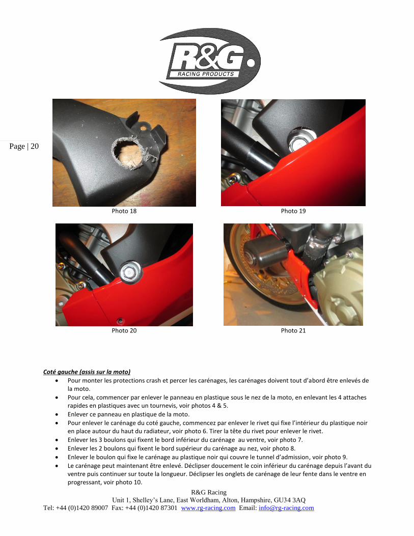
Photo 18 Photo 19
Photo 20 Photo 21
Coté gauche (assis sur la moto)
Pour monter les protections crash et percer les carénages, les carénages doivent tout d’abord être enlevés de la moto.
Pour cela, commencer par enlever le panneau en plastique sous le nez de la moto, en enlevant les 4 attaches rapides en plastiques avec un tournevis, voir photos 4 & 5.
Enlever ce panneau en plastique de la moto.
Pour enlever le carénage du coté gauche, commencez par enlever le rivet qui fixe l’intérieur du plastique noir en place autour du haut du radiateur, voir photo 6. Tirer la tête du rivet pour enlever le rivet.
Enlever les 3 boulons qui fixent le bord inférieur du carénage au ventre, voir photo 7.
Enlever les 2 boulons qui fixent le bord supérieur du carénage au nez, voir photo 8.
Enlever le boulon qui fixe le carénage au plastique noir qui couvre le tunnel d’admission, voir photo 9.
Le carénage peut maintenant être enlevé. Déclipser doucement le coin inférieur du carénage depuis l’avant du ventre puis continuer sur toute la longueur. Déclipser les onglets de carénage de leur fente dans le ventre en progressant, voir photo 10.
R&G Racing
Unit 1, Shelley’s Lane, East Worldham, Alton, Hampshire, GU34 3AQ
Tel: +44 (0)1420 89007 Fax: +44 (0)1420 87301 www.rg-racing.com Email: [email protected]
Page | 21
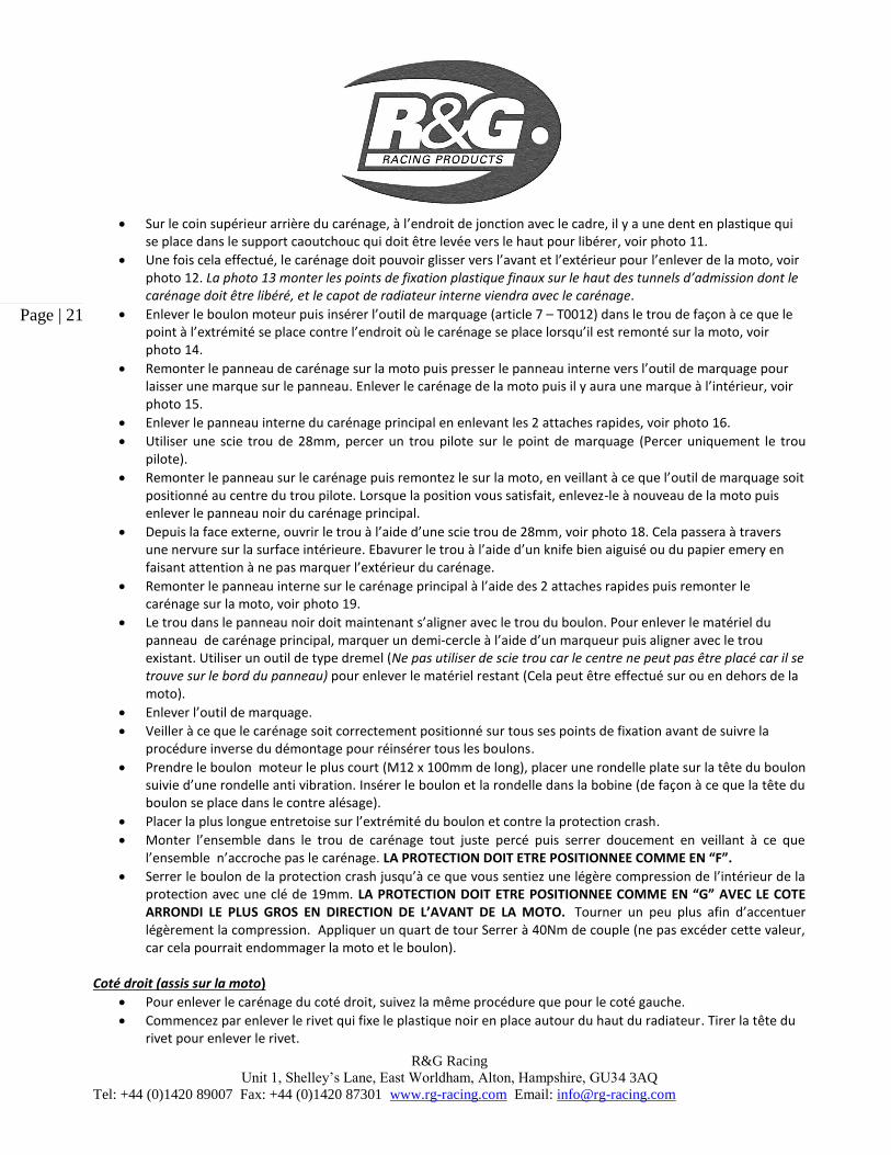
Sur le coin supérieur arrière du carénage, à l’endroit de jonction avec le cadre, il y a une dent en plastique qui se place dans le support caoutchouc qui doit être levée vers le haut pour libérer, voir photo 11.
Une fois cela effectué, le carénage doit pouvoir glisser vers l’avant et l’extérieur pour l’enlever de la moto, voir photo 12. La photo 13 monter les points de fixation plastique finaux sur le haut des tunnels d’admission dont le carénage doit être libéré, et le capot de radiateur interne viendra avec le carénage.
Enlever le boulon moteur puis insérer l’outil de marquage (article 7 – T0012) dans le trou de façon à ce que le point à l’extrémité se place contre l’endroit où le carénage se place lorsqu’il est remonté sur la moto, voir photo 14.
Remonter le panneau de carénage sur la moto puis presser le panneau interne vers l’outil de marquage pour laisser une marque sur le panneau. Enlever le carénage de la moto puis il y aura une marque à l’intérieur, voir photo 15.
Enlever le panneau interne du carénage principal en enlevant les 2 attaches rapides, voir photo 16.
Utiliser une scie trou de 28mm, percer un trou pilote sur le point de marquage (Percer uniquement le trou pilote).
Remonter le panneau sur le carénage puis remontez le sur la moto, en veillant à ce que l’outil de marquage soit positionné au centre du trou pilote. Lorsque la position vous satisfait, enlevez-le à nouveau de la moto puis enlever le panneau noir du carénage principal.
Depuis la face externe, ouvrir le trou à l’aide d’une scie trou de 28mm, voir photo 18. Cela passera à travers une nervure sur la surface intérieure. Ebavurer le trou à l’aide d’un knife bien aiguisé ou du papier emery en faisant attention à ne pas marquer l’extérieur du carénage.
Remonter le panneau interne sur le carénage principal à l’aide des 2 attaches rapides puis remonter le carénage sur la moto, voir photo 19.
Le trou dans le panneau noir doit maintenant s’aligner avec le trou du boulon. Pour enlever le matériel du panneau de carénage principal, marquer un demi-cercle à l’aide d’un marqueur puis aligner avec le trou existant. Utiliser un outil de type dremel (Ne pas utiliser de scie trou car le centre ne peut pas être placé car il se trouve sur le bord du panneau) pour enlever le matériel restant (Cela peut être effectué sur ou en dehors de la moto).
Enlever l’outil de marquage.
Veiller à ce que le carénage soit correctement positionné sur tous ses points de fixation avant de suivre la procédure inverse du démontage pour réinsérer tous les boulons.
Prendre le boulon moteur le plus court (M12 x 100mm de long), placer une rondelle plate sur la tête du boulon suivie d’une rondelle anti vibration. Insérer le boulon et la rondelle dans la bobine (de façon à ce que la tête du boulon se place dans le contre alésage).
Placer la plus longue entretoise sur l’extrémité du boulon et contre la protection crash.
Monter l’ensemble dans le trou de carénage tout juste percé puis serrer doucement en veillant à ce que l’ensemble n’accroche pas le carénage. LA PROTECTION DOIT ETRE POSITIONNEE COMME EN “F”.
Serrer le boulon de la protection crash jusqu’à ce que vous sentiez une légère compression de l’intérieur de la protection avec une clé de 19mm. LA PROTECTION DOIT ETRE POSITIONNEE COMME EN “G” AVEC LE COTE ARRONDI LE PLUS GROS EN DIRECTION DE L’AVANT DE LA MOTO. Tourner un peu plus afin d’accentuer légèrement la compression. Appliquer un quart de tour Serrer à 40Nm de couple (ne pas excéder cette valeur, car cela pourrait endommager la moto et le boulon).
Coté droit (assis sur la moto)
Pour enlever le carénage du coté droit, suivez la même procédure que pour le coté gauche.
Commencez par enlever le rivet qui fixe le plastique noir en place autour du haut du radiateur. Tirer la tête du rivet pour enlever le rivet.

R&G Racing
Unit 1, Shelley’s Lane, East Worldham, Alton, Hampshire, GU34 3AQ
Tel: +44 (0)1420 89007 Fax: +44 (0)1420 87301 www.rg-racing.com Email: [email protected]
Page | 22
Enlever les 3 boulons qui fixent le bord inférieur du carénage au ventre,
Enlever les 2 boulons qui fixent le bord supérieur du carénage au nez.
Enlever le boulon qui fixe le carénage au plastique noir qui couvre le tunnel d’admission.
Le carénage peut maintenant être enlevé. Déclipser le coin inférieur du carénage depuis l’avant du ventre puis continuer sur toute la longueur. Déclipser les onglets de carénage de leur fente dans le ventre en progressant.
Sur le coin supérieur arrière du carénage, à l’endroit de jonction avec le cadre, il y a une dent en plastique qui se place dans le support caoutchouc qui doit être levée vers le haut pour libérer.
Une fois cela effectué, le carénage doit pouvoir glisser vers l’avant et l’extérieur pour l’enlever de la moto.
Enlever le boulon moteur puis insérer l’outil de marquage (article 7 – T0012) dans le trou de façon à ce que le point à l’extrémité se place contre l’endroit où le carénage se place lorsqu’il est remonté sur la moto. Il y a une entretoise entre le moteur et le cadre qui pourrait tomber. Conservez-la en place lorsque vous placez l’outil de marquage/boulon.
Remonter le panneau de carénage sur la moto puis presser le panneau interne vers l’outil de marquage pour laisser une marque sur le panneau. Enlever le carénage de la moto puis il y aura une marque à l’intérieur.
Enlever le panneau interne du carénage principal en enlevant les 2 attaches rapides
Utiliser une scie trou de 28mm, percer un trou pilote sur le point de marquage (Percer uniquement le trou pilote).
Remonter le panneau sur le carénage puis remontez le sur la moto, en veillant à ce que l’outil de marquage soit positionné au centre du trou pilote. Lorsque la position vous satisfait, enlevez-le à nouveau de la moto puis enlevez le panneau du carénage principal.
Depuis la face externe, ouvrir le trou à l’aide d’une scie trou de 28mm. Cela passera à travers une nervure sur la surface intérieure. Ebavurer le trou à l’aide d’un knife bien aiguisé ou du papier Emery en faisant attention à ne pas marquer l’extérieur du carénage.
Remonter le panneau interne sur le carénage principal à l’aide des 2 attaches rapides puis remonter le carénage sur la moto.
Le trou dans le panneau noir doit maintenant s’aligner avec le trou du boulon. Pour enlever le matériel du panneau de carénage principal, marquer un demi-cercle à l’aide d’un marqueur puis aligner avec le trou existant. Utiliser un outil de type dremel (Ne pas utiliser de scie trou car le centre ne peut pas être placé car il se trouve sur le bord du panneau) pour enlever le matériel restant (Cela peut être effectué sur ou en dehors de la moto).
Enlever l’outil de marquage.
Veiller à ce que le carénage soit correctement positionné sur tous ses points de fixation avant de suivre la procédure inverse du démontage pour réinsérer tous les boulons.
Remonter le panneau noir en plastique qui se place au dessous du nez à l’aide des 4 attaches rapides d’origine.
Prendre le boulon moteur le plus long (M12 x 110mm de long), placer une rondelle plate sur la tête du boulon suivie d’une rondelle anti vibration. Insérer le boulon et la rondelle dans la bobine (de façon à ce que la tête du boulon se place dans le contre alésage).Placer la plus courte entretoise sur l’extrémité du boulon et contre la protection crash.
Monter l’ensemble dans le trou de carénage tout juste percé puis serrer doucement en veillant à ce que l’ensemble n’accroche pas le carénage. LA PROTECTION DOIT ETRE POSITIONNEE COMME EN “E”.
Serrer le boulon de la protection crash jusqu’à ce que vous sentiez une légère compression de l’intérieur de la protection avec une clé de 19mm. LA PROTECTION DOIT ETRE POSITIONNEE COMME EN “G” AVEC LE COTE ARRONDI LE PLUS GROS EN DIRECTION DE L’AVANT DE LA MOTO. Tourner un peu plus afin d’accentuer légèrement la compression. Appliquer un quart de tour Serrer à 40Nm de couple (ne pas excéder cette valeur, car cela pourrait endommager la moto et le boulon).
Placer le logo en caoutchouc dans le creux des 2 protections.

R&G Racing
Unit 1, Shelley’s Lane, East Worldham, Alton, Hampshire, GU34 3AQ
Tel: +44 (0)1420 89007 Fax: +44 (0)1420 87301 www.rg-racing.com Email: [email protected]
Page | 23
Mettre les capuchons de protections crash dans les 2 protections crash.
ISSUE 3 02/03/2017 (AR)
CONSUMER NOTICE
The catalogue description and any exhibition of samples are only broad indications of the Products and R&G may make design changes which do not
diminish their performance or visual appeal and supplying them in such state shall conform to the order. The Buyer acknowledges no representation or warranty (other than as to title) has been given or will apply to the Products other than those in R&G’s order or confirmation and the Buyer confirms it
has chosen the Products as being of merchantable quality and suitable for its particular purposes. Where R&G fits the Products or undertakes other
services it shall exercise reasonable skill and care and rectify any fault free of charge unless the workmanship has been disturbed. The Buyer is responsible for ensuring that the warranty on the motorcycle is not affected by the fitting of the Products. On return of any defective Products R&G
shall at its option either supply a replacement or refund the purchase money but shall not be liable if the Products have been modified or used or
maintained otherwise than in accordance with R&G’s or manufacturer’s instructions and good engineering practice or if the defect arises from accident or neglect. Other than identified above and subject to R&G not limiting its liability for causing death and personal injury, it shall not be liable for
indirect or consequential loss and otherwise its liability shall be limited to the amounts paid by the Buyer for the Products or the fitting or service
concerned. These terms do not affect the Buyer’s statutory rights.
R&G RACING RETURNS POLICY (NON-FAULTY GOODS)
Returns must be pre-authorised (if not pre-authorised the return will be rejected). Goods may only be returned direct to us if they were purchased direct
from us (customer must prove if necessary). Otherwise to be returned to original vendor. Goods must be in re-sellable condition, in the opinion of R&G
Racing. All returns are subject to a 25% restocking and handling fee (25% of the gross value exc. P&P – at the prevailing price at time of purchase). The customer must pay any and all carriage charges. No returns of discontinued products, unless within 14 days of purchase. This policy does not affect your
statutory rights and does not refer to faulty goods.


![Part II Color Oral Pathology Picture Booklet [2007-2008].pdf](https://img.pdfslide.us/doc/110x75/55cf99aa550346d0339e8d0f/part-ii-color-oral-pathology-picture-booklet-2007-2008pdf.jpg)


![Part II Color Oral Pathology Picture Booklet [2007-2008]](https://img.pdfslide.us/doc/110x75/55cf9c3e550346d033a92a93/part-ii-color-oral-pathology-picture-booklet-2007-2008.jpg)