Embed Size (px)
Citation preview
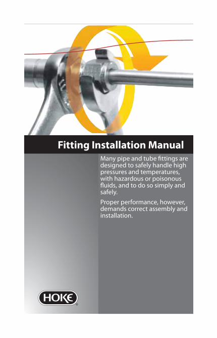
Many pipe and tube fi ttings are designed to safely handle high pressures and temperatures, with hazardous or poisonous fl uids, and to do so simply and safely.
Proper performance, however, demands correct assembly and installation.
Fitting Installation Manual

HOKE Incorporated405 Centura Court • PO Box 4866 (29305) • Spartanburg, SC 29303Phone (864) 574-7966 Fax (864) 587-0998www.hoke.com • [email protected]
Fitting Installation ManualFor HOKE Gyrolok® and Pipe Fittings
gyrolok®

2 Fitting Installation Manual
Tube Fitting Identifi cation Guide
Connector, Male:CM
Connector, Female:CF
Union:U
Reducing Union:RU
Bulkhead ConnectorMale: BCM
Bulkhead Connector,Female: BCF
Bulkhead Union:BU
Bulkhead Adapter:BA
Elbow, Male:LM
Elbow, Female:LF
Elbow, Union:LU
Male Branch Tee:TTM
Male Run Tee:TMT
Female Branch Tee:TTF
Female Run Tee:TFT
Union Tee:TTT
Union Cross:C
Reducer:R

Fitting Installation Manual 3
Cap:CP
Plug:P
Adapter, Male:AM
Adapter, Female:AF
Connector, O-ringStraight: COS
Adapter, O-ringStraight: AOS
Connector, Butt Weld:CBW
Elbow, Butt Weld:LBW
Connector, Socket Weld:CW
Elbow, Socket Weld:LW
Tube Insert:TI
Port Connector:PC
Nut:N
Ferrule, Rear:FR
Ferrule, Front:FF
Nut and Ferrule Safety Changer:SCNF
Ferrule Safety Changer:SCF

4 Fitting Installation Manual
About HOKE...HOKE Incorporated, founded in 1925 by Samuel W. HOKE, has evolved into an international fl uid control products company serving key markets around the globe. HOKE, a company of CIRCOR International, has multiple manufacturing facilities in the United States and Europe. Combined with distributor inventory facilities in virtually every corner of the world, HOKE is well positioned to meet the needs of its market-place.
HOKE specializes in the design, manufacture, and distribution of high quality, precision instrumentation valves, fi ttings and sampling cylin-ders. Applications require HOKE valves and fi ttings for safe control of fl uids in many diff erent industries, including: chemical and petrochemi-cal plants, oil and gas gathering, refi ning, gas and electric utilities, pulp and paper mills, and laboratories, as well as alternative fuel vehicles and nuclear power plants. HOKE also supplies the OEM market, includ-ing analyzer equipment manufacturers, with products designed to meet their needs.
Corporate staff , as well as regionally located industry specialists and corporate offi ces, provide assistance to distributors and customers with technical support and training. Valve and fi tting workshops, which include important information about tubing preparation, are frequent-ly conducted on-site helping the user achieve the maximum value that HOKE products have to off er.
Table of ContentsTube Fitting Identifi cation Guide 2About HOKE... 4
Table of Contents 4About this manual... 5This manual will: 5Pipe 6Pipe Threads 6
Straight Threads 7Taper Threads 7
Thread Tape 8Applying Thread Tape 8
The Pipe vs. Tubing Decision 9Tubing 10
The Advantages of Tubing: 10
Tubing Variables 12Temperature Derating 18Care and Handling of Tubing 19Bending the Tubing 21Bending Information Charts 22HOKE Gyrolok Assembly Instruc. 30
Sizes 1˝, 25mm and Smaller 30Sizes 1¼˝, 28mm and Larger 31All Sizes 31
Installation Aids 33HOKE Safety Check List 38

Fitting Installation Manual 5
About this manual...Many tube and pipe fi ttings are designed to safely handle high pressures and temperatures, with hazardous or poisonous fl uids, and to do so simply and safely.
Proper performance, however, demands correct assembly and installation.
Not only must the fi tting product be used correctly but the mating product, meaning tube or pipe, must be selected, handled, and prepared in a manner to ensure maximum fi tting performance.
This manual will:1. Help assure maximum user awareness of key installation
procedures and considerations.2. Familiarize the user with pipe and pipe fi ttings, including their
key characteristics, assembly procedures, and usage precautions.3. Compare pipe and tube.4. Review key tubing installation practices including: selection,
cutting, deburring, and bending.5. Familiarize the user with tube fi ttings, in general, including
their key characteristics, important diff erences between manufacturers, various assembly procedures, and usage precautions.
Keep this manual readily available. You’ll fi nd it to be a handy reference tool.

6 Fitting Installation Manual
PipePipe, by defi nition, is a hollow, elongated metallic structure used to convey fl uids. The same defi nition, in fact, applies to tube.
Pipe sizes, however, are not what might be expected. For example, ¼˝
nominal bore (NB) pipe has an outside diameter of 0.540˝. ½˝ pipe has an actual outside diameter of 0.840˝. Wall thicknesses, expressed by a schedule number, may vary. The greater the wall thickness, the higher the schedule number and the higher the pressure rating of the pipe.
Pipe Threads The most common method of joining pipe is with threads. Although there are many pipe thread specifi cations, there are in general only two primary types; straight and taper. NPT threads found on HOKE Gyrolok tube fi ttings exceed the requirements of ANSI B1.2.1. This results in more consistent assembly and minimized thread galling.
PIPE SIZE ACTUAL OUTSIDE DIAMETER⁄˝ NB 0.405˝/10.3 mm¼˝ NB 0.540˝/13.7 mm⁄˝ NB 0.675˝/17.1 mm½˝ NB 0.840˝/21.3 mm¾˝ NB 1.050˝/26.7 mm1˝ NB 1.315˝/33.4 mm
TaperStraight
O-ring

Fitting Installation Manual 7
Straight ThreadsWhen joining pipe or tube there are two functions to be accomplished: joining and seal-ing. Straight threads are used for joining, only. Sealing is accomplished by means of a gasket or o-ring.
The Society of Automotive Engineers (SAE) has developed specifi cations for specifi c straight thread and o-ring combinations. Shown to the left are two drawings. The top one is of an SAE straight port connec-tion. The bottom is of an adjustable or positionable one.
The positionable port utilizes a separate nut and washer to be tightened against the o-ring for sealing. It is important to ensure that the nut is suffi ciently backed off prior to installation to prevent pinching the o-ring, which could result in a leaking connection.
Taper ThreadsTaper threads such as NPT, which stands for National Pipe Taper, are intended to provide a seal but must be used with a thread tape or liquid sealant to do so. No separate o-ring or gasket is needed.
Caution: O-rings, gaskets, thread tapes, and liquid sealants must each be considered for media compatibility as well as temperature rating.
O-ring
Body Hex
Straight Thread
Straight Port Connection
Nut
O-ring
Straight Thread
Washer
Positionable Port Connection
8 Fitting Installation Manual
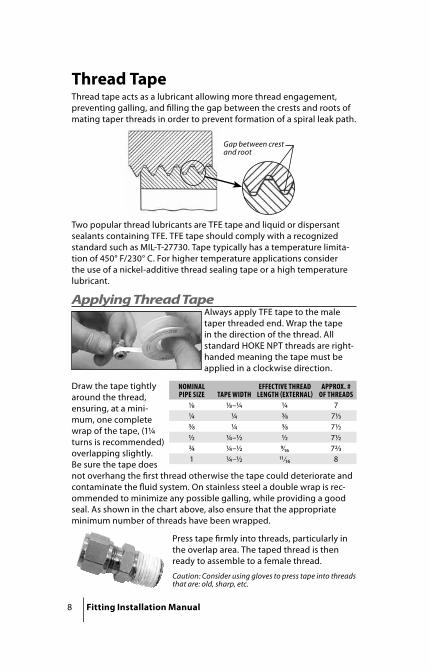
Thread TapeThread tape acts as a lubricant allowing more thread engagement, preventing galling, and fi lling the gap between the crests and roots of mating taper threads in order to prevent formation of a spiral leak path.
Two popular thread lubricants are TFE tape and liquid or dispersant sealants containing TFE. TFE tape should comply with a recognized standard such as MIL-T-27730. Tape typically has a temperature limita-tion of 450° F/230° C. For higher temperature applications consider the use of a nickel-additive thread sealing tape or a high temperature lubricant.
Applying Thread TapeAlways apply TFE tape to the male taper threaded end. Wrap the tape in the direction of the thread. All standard HOKE NPT threads are right-handed meaning the tape must be applied in a clockwise direction.
Draw the tape tightly around the thread, ensuring, at a mini-mum, one complete wrap of the tape, (1¼ turns is recommended) overlapping slightly. Be sure the tape does not overhang the fi rst thread otherwise the tape could deteriorate and contaminate the fl uid system. On stainless steel a double wrap is rec-ommended to minimize any possible galling, while providing a good seal. As shown in the chart above, also ensure that the appropriate minimum number of threads have been wrapped.
Press tape fi rmly into threads, particularly in the overlap area. The taped thread is then ready to assemble to a female thread.
Caution: Consider using gloves to press tape into threads that are: old, sharp, etc.
Gap between crest and root
NOMINAL PIPE SIZE TAPE WIDTH
EFFECTIVE THREAD LENGTH EXTERNAL
APPROX. # OF THREADS
⁄ ⁄–¼ ¼ 7¼ ¼ ⁄ 7⁄⁄ ¼ ⁄ 7½½ ¼–½ ½ 7½¾ ¼–½ ⁄₁₆ 7⁄1 ¼–½ ⁄₁₆ 8

Fitting Installation Manual 9
The Pipe vs. Tubing DecisionFor a long period of time, threaded pipe was the most common method of joining and sealing most fl uid line systems. Even today pipe continues to off er several benefi ts.
The advantages of threaded pipe are:1. Simplicity.2. Consistent assembly.3. Lower fi tting cost.
The fact is, however, that pipe involves many hidden costs.
Pipe’s disadvantages are:1. Lower strength to weight ratio—in order to accommodate
threads, added size and weight are required.2. Higher material cost of pipe—added weight means added
material and added cost.3. Pipe is not easily bendable—except for certain specifi c situations,
a direction change requires a fi tting.4. Sharp bends or corners cause greater pressure drops.5. Pipe is typically prepared and joined with NPT threads that
require the use of a thread tape or lubricant. TFE tape has a lower temperature rating than stainless steel. Tape suitability must be considered for the application.
6. Size identifi cation is diffi cult—recognition requires experience.

10 Fitting Installation Manual
TubingToday, tubing is more cost eff ective and increasingly more commonly used than pipe.
Tubing, like pipe, is a hollow elongated metal structure. Unlike pipe, however, it is easily identifi able. Tube size is designated by its outside diameter. ¼˝
tube actually has an outside diameter of ¼˝. Various wall thicknesses are available which change the inside diameter, but not the outside diameter.
Tubing is typically joined through the use of tube fi ttings which are also responsible for providing leak-tight sealing. No special tubing preparation for a tube fi tting connection is required, other than a squarely cut, deburred end. Note that tube fi ttings which incorporate a taper thread end will require a tape or thread lubricant on the taper thread end.
The Advantages of Tubing:1. Easy Size Identifi cation
- Saves time and money2. Tubing has a higher strength to weight ratio because it doesn’t
require extra wall thickness to accommodate threads.
¼˝ Pipe = 0.540˝ O.D. ¼˝ Tube = 0.250˝ O.D.
Wall Thickness necessary for Pressure Containment

Fitting Installation Manual 11
- Reduces material cost3. Bendability
- Reduces connections and possible leak paths- Reduces time, labor, and material costs
- Lowers pressure drops4. Tubing Simplifi es Maintenance
- Tubing and tube fi ttings are more easily disassembled and
reassembled since fewer connections are involved5. Tubing Does Not Require Thread Tape/Lubricant
- Reduces installation time- Assures maximum system temperature rating- Ensures a cleaner system
12 Fitting Installation Manual
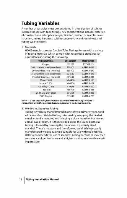
Tubing VariablesA number of variables must be considered in the selection of tubing suitable for use with tube fi ttings. Key considerations include: materials of construction and applicable specifi cation, welded or seamless con-struction, tubing hardness, tubing concentricity and roundness, and tubing wall thickness.
1. Materials HOKE manufactures its Gyrolok Tube Fittings for use with a variety of tubing materials which comply with recognized standards (or equivalents) including the following:
Note: it is the user’s responsibility to assure that the tubing selected is compatible with the process fl uid, temperature, and environment.
2. Welded vs. Seamless TubingTubing is typically manufactured in one of two primary types, weld-ed or seamless. Welded tubing is formed by wrapping the heated metal around a mandrel, and bringing it close together, but leaving a small gap or seam. It is then welded along the seam. Seamless tubing is formed by drawing the metal over a precisely sized mandrel. There is no seam and therefore no weld. While properly manufactured welded tubing is suitable for use with tube fi ttings, HOKE recommends the use of seamless tubing because of increased consistency of performance and a higher maximum allowable work-ing pressure.
TUBING MATERIAL UNS NUMBER SPECIFICATIONCopper C12200 ASTM B-75
304 stainless steel (seamless) S30400 ASTM A-213304 stainless steel (welded) S30400 ASTM A-249
316 stainless steel (seamless) S31600 ASTM A-213316 stainless steel (welded) S31600 ASTM A-249
Monel® 400 N04400 ASTM B-165Inconel® 600 N06600 ASTM B-167
Hastelloy® C-276 N10276 ASTM B-622Titanium R56400 ASTM B-338
254 SMO alloy steel S31254 ASTM A-2692205 Duplex S31803 ASTM A-789
Fitting Installation Manual 13
3. Tubing HardnessProper tube fi tting performance demands that the ferrules of the fi tting be signifi cantly harder than the tubing on which it is used. Maximum allowable surface hardness for various tubing materi-als are:
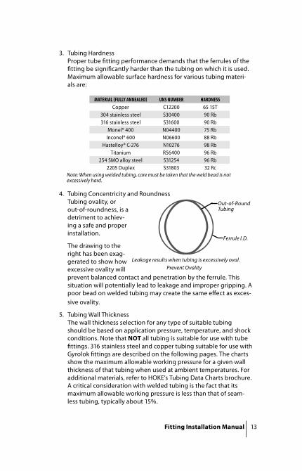
4. Tubing Concentricity and RoundnessTubing ovality, or out-of-roundness, is a detriment to achiev-ing a safe and proper installation.
The drawing to the right has been exag-gerated to show how excessive ovality will prevent balanced contact and penetration by the ferrule. This situation will potentially lead to leakage and improper gripping. A poor bead on welded tubing may create the same eff ect as exces-sive ovality.
5. Tubing Wall ThicknessThe wall thickness selection for any type of suitable tubing should be based on application pressure, temperature, and shock conditions. Note that NOT all tubing is suitable for use with tube fi ttings. 316 stainless steel and copper tubing suitable for use with Gyrolok fi ttings are described on the following pages. The charts show the maximum allowable working pressure for a given wall thickness of that tubing when used at ambient temperatures. For additional materials, refer to HOKE’s Tubing Data Charts brochure. A critical consideration with welded tubing is the fact that its maximum allowable working pressure is less than that of seam-less tubing, typically about 15%.
Note: When using welded tubing, care must be taken that the weld bead is not excessively hard.
MATERIAL FULLY ANNEALED UNS NUMBER HARDNESSCopper C12200 65 15T
304 stainless steel S30400 90 Rb316 stainless steel S31600 90 Rb
Monel® 400 N04400 75 RbInconel® 600 N06600 88 Rb
Hastelloy® C-276 N10276 98 RbTitanium R56400 96 Rb
254 SMO alloy steel S31254 96 Rb2205 Duplex S31803 32 Rc
Out-of-Round Tubing
Ferrule I.D.
Prevent OvalityLeakage results when tubing is excessively oval.

14 Fitting Installation Manual
304
and
316
Stai
nles
s Ste
el A
nnea
led
Seam
less
Tubi
ng, S
3040
0 (A
STM
A-2
13) o
r Equ
ival
ent
Max
imu
m A
llo
wab
le W
ork
ing
Pre
ssu
re (p
si) f
or
Frac
tio
nal
Siz
esA
llow
able
Str
ess
= 1
8,75
0 p
si b
etw
een
-20°
F a
nd
100°
F
TUBI
NGO.
D.IN
WAL
L THI
CKNE
SS I
N
.010
.012
.016
.020
.028
.035
.049
.065
.083
.095
.109
.120
.134
.148
.156
.180
.188
⁄
5690
6990
9820
1295
0⁄
4590
5890
8590
1097
0⁄
30
0038
1055
1071
0010
290
¼22
2028
1040
4051
6075
6010
290
⁄26
3033
3048
1066
2086
80½
1950
2460
3520
4790
6300
7350
⁄19
5027
8037
6049
2057
1067
00¾
1620
2300
3100
4030
4670
5440
6060
⁄13
8019
6026
3034
1039
5045
9051
001
1200
1700
2280
2960
3410
3960
4400
1¼18
1023
4026
9031
2034
6039
0043
4046
0053
901½
1930
2230
2570
2850
3200
3560
3770
4410
4620
216
3018
8020
8023
4025
9027
4031
9033
50
Fact
or o
f saf
ety=
4, c
onsi
deri
ng te
nsile
str
engt
h to
be
75,0
00 p
si a
t roo
m te
mpe
ratu
re.

Fitting Installation Manual 15
304
and
316
Stai
nles
s Ste
el A
nnea
led
Seam
less
Tubi
ng,
S304
00 (A
STM
A-2
13) o
r Equ
ival
ent
Max
imu
m A
llo
wab
le W
ork
ing
Pre
ssu
re (b
ar) f
or
Met
ric
Size
sA
llow
able
Str
ess
= 1
29.3
MPa
bet
wee
n -2
9° C
an
d 38
° C
TUBI
NGO.
D.M
M
WAL
L TH
ICKN
ESS
MM
.5.6
.7.8
1.0
1.2
1.5
1.6
1.8
2.0
2.2
2.5
3.0
4.0
342
452
261
971
790
64
311
381
452
527
674
819
629
133
743
253
268
072
98
214
247
315
386
497
534
1019
524
830
238
741
647
753
512
161
204
248
317
340
388
437
1417
421
026
828
832
736
840
947
415
161
196
249
267
303
341
379
439
1615
118
323
224
928
331
735
240
750
118
134
161
205
219
249
279
310
357
438
2012
014
518
319
622
324
927
731
838
922
108
131
166
177
201
225
249
286
350
2595
115
145
155
176
197
217
250
304
2885
102
129
138
156
174
192
221
268
368
3016
217
920
524
934
132
151
167
192
232
318
3816
019
426
350
145
197
Fact
or o
f saf
ety=
4, c
onsi
deri
ng te
nsile
str
engt
h to
be
517.
1 M
Pa a
t roo
m te
mpe
ratu
re.

16 Fitting Installation Manual
Copp
er A
nnea
led
Seam
less
Tubi
ng, C
1220
0 (A
STM
B-7
5) o
r Equ
ival
ent
Max
imu
m A
llo
wab
le W
ork
ing
Pre
ssu
re (p
si) f
or
Frac
tio
nal
Siz
esA
llow
able
Str
ess
= 6
,000
psi
bet
wee
n -2
0° F
an
d 10
0° F
TUBI
NGO.
D.IN
WAL
L TH
ICKN
ESS
IN.
.010
.012
.016
.020
.028
.032
.035
.049
.065
.083
.095
.109
.120
.134
.148
.156
.180
.188
⁄
1650
2120
3150
4000
⁄27
7032
6036
30⁄
18
0021
3023
4034
80¼
1320
1540
1690
2560
3500
⁄10
0010
9016
2022
5029
70½
800
1180
1620
2160
⁄63
093
012
7016
8019
70¾
510
760
1040
1350
1580
1860
⁄44
064
088
011
4013
4015
701
380
560
760
990
1160
1350
1500
1¼60
078
091
010
6011
7013
3014
9015
8018
301½
640
750
870
960
1090
1220
1300
1500
1570
255
065
071
080
090
095
010
9011
50
Fact
or o
f Saf
ety=
5, c
onsi
deri
ng te
nsile
str
engt
h to
be
30,0
00 p
si a
t roo
m te
mpe
ratu
re.

Fitting Installation Manual 17
Copp
er A
nnea
led
Seam
less
Tubi
ng, C
1220
0 (A
STM
B-7
5) o
r Equ
ival
ent
Max
imu
m A
llo
wab
le W
ork
ing
Pre
ssu
re (b
ar) f
or
Met
ric
Size
sA
llow
able
Str
ess
= 4
1 M
Pa b
etw
een
-29°
C a
nd
38° C
TUBI
NGO.
D.M
M
WAL
L TH
ICKN
ESS
MM
.5.6
.7.8
1.0
1.2
1.5
1.6
1.8
2.0
2.2
2.5
3.0
4.0
320
524
04
150
176
223
276
695
112
143
179
232
248
882
103
129
169
181
1064
8110
113
214
116
318
312
5367
8310
811
513
215
014
5770
9097
111
126
140
163
1553
6584
9010
311
713
115
116
5061
7984
9610
812
114
017
418
4353
6873
8494
105
121
151
2039
4862
6676
8695
4113
622
3543
5559
6877
8497
120
2530
3848
5259
6673
8510
428
2733
4346
5259
6575
9212
630
5460
7086
116
3251
5765
8010
838
5466
9050
5068
Fact
or o
f saf
ety=
5, c
onsi
deri
ng te
nsile
str
engt
h to
be
205
MPa
at r
oom
tem
pera
ture
.

18 Fitting Installation Manual
Temperature DeratingAs application temperature increases maximum allowable working pressure decreases. The following chart provides derating factors for copper and 316 stainless steel tubing. To use, locate the maximum allowable working pressure for specifi c tubing in the tubing data charts. Multiply that number by the number in the chart below appli-cable to the application temperature.
Example: Determine the maximum allowable working pressure for 12mm 316 stainless steel annealed seamless tubing with a wall thick-ness of 1.5mm when used at 427° C.
Maximum allowable working pressure at ambient temperature(from tubing data charts) = 317 bar
Derating factor for 427° C = 0.84
Maximum allowable working pressureat 427° C = 317 bar × 0.84 = 266 bar
TEMPERATURES COPPER TYPE 316
°F °C
SEAMLESSANNEALED
TUBING SPEC.ASTM B75
SEAMLESSANNEALED
TUBING SPEC.ASTM A213
WELDEDANNEALED
TUBING SPEC.ASTM A249
-20 to 100 -29 to 38 1.00 1.00 1.00150 66 0.85 1.00 1.00200 93 0.80 1.00 1.00300 149 0.78 0.98 0.98400 204 0.50 0.96 0.96500 260 — 0.96 0.96600 316 — 0.90 0.90700 371 — 0.87 0.87800 427 — 0.84 0.84
1000 538 — 0.81 0.811200 649 — 0.39 0.39

Fitting Installation Manual 19
Care and Handling of TubingProper control of tubing variables is not only a function of how the tubing is manufactured. Improper care and handling of the tubing can cause correctly manufactured tubing to become unsuitable for use with a tube fi tting.
1. Notify Supplier of Need for Careful Handling of Tubing Not only should tubing be ordered to applicable specifi cations but appropriate precautions must be taken to protect key tubing characteristics through each handling and preparation phase.
2. Protect Tubing Surface from DamageA smooth, unscratched tubing surface is essential for achieving a proper seal with a tube fi tting. Do not drag straight tubing from storage racks.
3. Uncoil Tubing CorrectlyWhen working with coiled tubing, do not uncoil more than is needed and then recoil. Excessive uncoiling and recoiling will work harden the tubing, potentially increasing surface hardness beyond that which is suitable for use with tube fi ttings. Uncoil tubing by holding one end and unrolling the coiled section.
4. Properly Cut TubingTubing must be cut squarely to maximize fi tting function. While a hacksaw can be used, HOKE recommends the use of a tube cut-ter. Ensure cutting wheel is appropriate for tubing material.
Tube CutterA. Ensure cutting wheel is sharp
IncorrectCorrect
HoldUncoil
Pull
Hold
Cutting Wheel
Adjustable Knob
20 Fitting Installation Manual
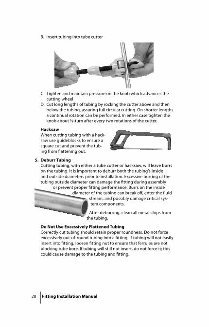
B. Insert tubing into tube cutter
C. Tighten and maintain pressure on the knob which advances the cutting wheel
D. Cut long lengths of tubing by rocking the cutter above and then below the tubing, assuring full circular cutting. On shorter lengths a continual rotation can be performed. In either case tighten the knob about ⁄-turn after every two rotations of the cutter.
HacksawWhen cutting tubing with a hack-saw use guideblocks to ensure a square cut and prevent the tub-ing from fl attening out.
5. Deburr TubingCutting tubing, with either a tube cutter or hacksaw, will leave burrs on the tubing. It is important to deburr both the tubing’s inside and outside diameters prior to installation. Excessive burring of the tubing outside diameter can damage the fi tting during assembly
or prevent proper fi tting performance. Burrs on the inside diameter of the tubing can break off , enter the fl uid
stream, and possibly damage critical sys-tem components.
After deburring, clean all metal chips from the tubing.
Do Not Use Excessively Flattened TubingCorrectly cut tubing should retain proper roundness. Do not force excessively out-of-round tubing into a fi tting. If tubing will not easily insert into fi tting, loosen fi tting nut to ensure that ferrules are not blocking tube bore. If tubing will still not insert, do not force it; this could cause damage to the tubing and fi tting.
Fitting Installation Manual 21
Bending the TubingAs we’ve already noted, tube bendability is one of the outstand-ing advantages of using tubing. Careful measurement and accurate bending are essential to achieving desired installation requirements including the achievement of a correct tube and fi tting connection.
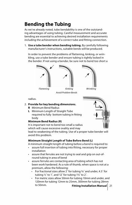
1. Use a tube bender when bending tubing. By carefully following manufacturer’s instructions, suitable bends will be produced.
In order to prevent the problems of fl attening, kinking, or wrin-kling, use a tube bender and ensure tubing is tightly locked in the bender. If not using a bender, be sure not to bend too short a
radius.
2. Provide for key bending dimensions.R Minimum Bend RadiusL Minimum Length of Straight Tube
required to fully bottom tubing in fi tting body
Minimum Bend Radius (R) It is important not to bend too small a radius which will cause excessive ovality and may lead to weakening of the tubing. Use of a proper tube bender will avoid this problem.
Minimum Straight Length of Tube Before Bend (L)A minimum straight length of tubing before a bend is required to:• assure full insertion of tubing into fi tting, necessary for proper
installation• assure that ferrules are not trying to seal and grip on out-of-
round tubing in area of bend• assure ferrules are contacting area of tubing which has not
been work hardened. As a rule of thumb, when space is not at a premium, allow the following:• For fractional sizes allow 2˝ for tubing ⁄˝ and under, 4.5˝ for
tubing ½˝ to 1˝, and 12˝ for tubing 1¼˝ to 2˝.• For metric sizes allow 50mm for tubing 10mm and under, and
120mm for tubing 12mm to 25mm, 300mm for tubing 28mm to 50mm.
Flattening Kinking Wrinkling
Avoid Problem Bends
RR
L
22 Fitting Installation Manual
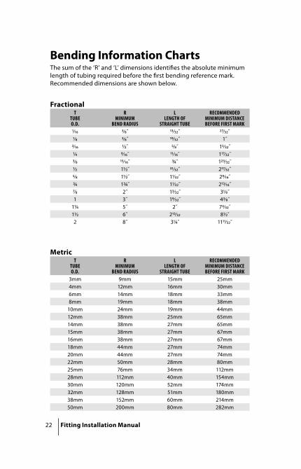
Bending Information ChartsThe sum of the ‘R’ and ‘L’ dimensions identifi es the absolute minimum length of tubing required before the fi rst bending reference mark. Recommended dimensions are shown below.
TTUBEO.D.
R MINIMUM
BEND RADIUS
LLENGTH OF
STRAIGHT TUBE
RECOMMENDEDMINIMUM DISTANCEBEFORE FIRST MARK
⁄ ⁄˝ ⁄˝ ⁄˝⁄ ⁄˝ ⁄˝ 1˝⁄ ½˝ ⁄˝ 1⁄˝¼ ⁄˝ ⁄˝ 1⁄˝⁄ ⁄˝ ¾˝ 1⁄˝½ 1½˝ ⁄˝ 2⁄˝⁄ 1½˝ 1⁄˝ 2⁄˝¾ 1¾˝ 1⁄˝ 2⁄˝⁄ 2˝ 1⁄˝ 3⁄˝1 3˝ 1⁄˝ 4⁄˝
1¼ 5˝ 2˝ 7⁄˝1½ 6˝ 2⁄ 8½˝2 8˝ 3¼˝ 11⁄˝
TTUBEO.D.
R MINIMUM
BEND RADIUS
LLENGTH OF
STRAIGHT TUBE
RECOMMENDEDMINIMUM DISTANCEBEFORE FIRST MARK
3mm 9mm 15mm 25mm4mm 12mm 16mm 30mm6mm 14mm 18mm 33mm8mm 19mm 18mm 38mm
10mm 24mm 19mm 44mm12mm 38mm 25mm 65mm14mm 38mm 27mm 65mm15mm 38mm 27mm 67mm16mm 38mm 27mm 67mm18mm 44mm 27mm 74mm20mm 44mm 27mm 74mm22mm 50mm 28mm 80mm25mm 76mm 34mm 112mm28mm 112mm 40mm 154mm30mm 120mm 52mm 174mm32mm 128mm 51mm 180mm38mm 152mm 60mm 214mm50mm 200mm 80mm 282mm
Metric
Fractional

Fitting Installation Manual 23
3. Tubing LayoutBefore marking the tubing for bending, it is important that a com-plete layout be identifi ed including consideration, where appropri-ate, of the use of expansion loops, off sets, staggered union loca-tions, and vertical ganging. Always allow suffi cient access to utilities and other equipment requiring maintenance.
Expansion LoopsDo not use a straight length of tube to connect two in-line fi tting ends. Such an approach makes installation very diffi cult and does not compensate for temperature change.
Set the ends so they are not in line and use expansion loops. Expansion loops allow the tubing and entire system to self-compen-sate for temperature change while not only simplifying assembly and disassembly but also ensuring a safer system.
Off set Bends and Stagger Union LocationsOff set bends are used to increase accessibility to tube fi tting unions for maintenance purposes. When off setting in a ganged run, stagger the union locations to further ensure ease of access.
Vertically Gang TubingTo the maximum extent possible, tubing should be ganged verti-cally rather than horizontally. Vertical ganging prevents the collec-tion of dirt or any potentially corrosive medium. Vertical ganging additionally increases system safety, since, for example, fl oor-level horizontally ganged tubing may be stepped on.
Correct
Expansion Loop
Incorrect
DON’TDO
Correct Off setting
24 Fitting Installation Manual
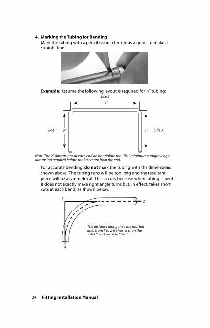
4. Marking the Tubing for BendingMark the tubing with a pencil using a ferrule as a guide to make a straight line.
Example: Assume the following layout is required for ¼˝ tubing:
For accurate bending, do not mark the tubing with the dimensions shown above. The tubing runs will be too long and the resultant piece will be asymmetrical. This occurs because when tubing is bent it does not exactly make right angle turns but, in eff ect, takes short cuts at each bend, as shown below.
X
YZ
The distance along the tube (dotted line) from X to Z is shorter than the solid lines from X to Y to Z.
4˝
2˝2˝
Side 2
Side 1 Side 3
Note: The 2˝ dimensions at each end do not violate the 1⁄̋ minimum straight length dimension required before the fi rst mark from the end.
Fitting Installation Manual 25
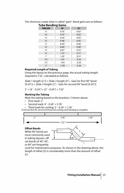
The shortcuts create what is called “gain”. Bend gains are as follows:
Required Length of TubingUsing the layout on the previous page, the actual tubing length required is 7.52˝, calculated as follows:
[Side 1 length (2˝)] + [Side 2 length (4˝) - Gain for fi rst 90° bend (0.24˝)] + [Side 3 length (2˝) - Gain for second 90° bend (0.24˝)]
2˝ + [4˝ - 0.24˝] + [2˝ - 0.24˝] = 7.52˝
Marking the TubingMark the tubing based on the brackets [ ] shown above:• First mark: 2˝• Second mark: 4˝ - 0.24˝ = 3.76˝• Third mark for cutting: 2˝ - 0.24˝ = 1.76˝
To ensure best fi t, we recommend not cutting until bending is complete.
Off set BendsWhile 90° bends are most commonly used in tubing layouts, off -set bends of 30°, 45°, or 60° are frequently used for maintenance purposes. As shown in the drawing above, the length of off set (S) is considerably more than the amount of off set (L).
TUBE SIZE 90° 45°⁄˝ 0.16˝ 0.02˝⁄˝ 0.19˝ 0.02˝¼˝ 0.24˝ 0.02˝⁄˝ 0.48˝ 0.05˝½˝ 0.64˝ 0.06˝⁄˝ 0.80˝ 0.08˝¾˝ 0.97˝ 0.10˝⁄˝ 1.13˝ 0.11˝1˝ 1.29˝ 0.13˝
1¼˝ 1.61 0.161½˝ 1.94 0.202˝ 2.58 0.26
Tube Bending Gains
L
S
45°
7.52˝
2˝ 3.76˝ 1.76˝

26 Fitting Installation Manual
Use the following chart to determine the appropriate off set length for a given amount of off set.
30° OFFSET 45° OFFSET L S L S1 2 1 1⁄
1⁄ 2¼ 1⁄ 1⁄1¼ 2½ 1¼ 1⁄1⁄ 2¾ 1⁄ 1⁄1½ 3 1½ 2⁄1⁄ 3¼ 1⁄ 2⁄1¾ 3½ 1¾ 2⁄1⁄ 3¾ 1⁄ 2⁄2 4 2 2⁄
2⁄ 4¼ 2⁄ 32¼ 4½ 2¼ 3⁄2⁄ 4¾ 2⁄ 3⁄2½ 5 2½ 3⁄2⁄ 5¼ 2⁄ 3⁄2¾ 5½ 2¾ 3⁄2⁄ 5¾ 2⁄ 4⁄3 6 3 4¼
3⁄ 6¼ 3⁄ 4⁄3¼ 6½ 3¼ 4⁄3⁄ 6¾ 3⁄ 4⁄3½ 7 3½ 4⁄3⁄ 7¼ 3⁄ 5⁄3¾ 7½ 3¾ 5⁄3⁄ 7¾ 3⁄ 5⁄4 8 4 5⁄
Off set Bend Dimensions (dimensions in inches)
The specifi c length required for the off set, which is what will need to be marked for bending, is determined by multiplying the amount of off set by an amount specifi c to the off set angle.
Example: As shown above, the specifi c length of tubing required to provide 1˝ of off set with a 30° angle is 2˝:
Off set Amount (1˝) × Multiplier for 30° Angle (2) = 2˝ Off set Length
LS
angle
OFFSET ANGLE MULTIPLIER
30° 245° 1.41460° 1.155
Off set Calculations

Fitting Installation Manual 27
5. Bending the TubingBest bends are produced by using tube benders specifi c to the tub-ing size.
Note the proper callout of tube size on the bender.
Tube Size
0

28 Fitting Installation Manual
90° Bends
• Locate the mark in the bender so that it is tangent to the 90° mark on the bender’s dial. Lock the tubing in place to avoid problem bends.
• Bend the tubing by smoothly swinging the upper arm down. Align the “0” on the upper arm with the “90” on the dial. Allow for about 3° of springback.
Reverse Bends• Since benders only bend in one
direction, it is critical when reverse bending to ensure that the tubing is properly aligned in the bender.
0 459
0
180
3°
Reverse Bend
0 459
0
180
Fitting Installation Manual 29
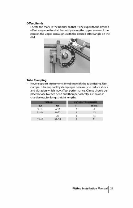
Off set Bends• Locate the mark in the bender so that it lines up with the desired
off set angle on the dial. Smoothly swing the upper arm until the zero on the upper arm aligns with the desired off set angle on the dial.
Tube Clamping• Never support instruments or tubing with the tube fi tting. Use
clamps. Tube support by clamping is necessary to reduce shock and vibration which may aff ect performance. Clamp should be placed close to each bend and then periodically, as shown in chart below, for long straight lengths.
0
90
180
45
TUBE O.D. SPACING BETWEEN CLAMPSINCH MM FT METERS¼–½ 6-12 3 .9⁄–⁄ 14-22 4 1.2
1 25 5 1.51¼–2 32–50 7 2.1

30 Fitting Installation Manual
HOKE Gyrolok Assembly InstructionsSizes 1̋ , 25mm and SmallerManual AssemblyUse the following instructions when initially setting ferrules onto either tubing, or the tube stub end of certain fi ttings (e.g. adapters, port connectors, and reducers). Note that for tub-ing sizes larger than ½˝, or 12mm, the use of a presetting tool, either manual or hydraulic, may apply.
1. Loosen the fi tting nut.2. Firmly insert the tubing into the fi tting assembly. Proper assembly
requires that the tubing be fully bottomed in the fi tting body. Note: Use of the HOKE Gyrogage, explained below, will allow the assembler to confi rm proper tube insertion.
3. Establish a consistent starting point for wrench tightening.For sizes under ½˝, fi nger tightening of the fi tting nut is suffi cient.
For sizes ½˝ and above, tighten the fi tting nut until the tubing will not rotate. If it is not possible to determine tubing rotation then, while supporting the body with a backup wrench, use a wrench to tighten the fi tting nut an additional ¼-turn past fi nger-tight.
4. Mark the fi tting body and nut at the 12:00 position with a readily visible marking.
5. While supporting the body with a backup wrench, tighten the nut with a wrench 1¼-turns by going completely around past the 12:00 position to the 3:00 position. Note that if a Gyrogage is used, the mark made on the tubing will become visible at the back of the nut when the nut has been suffi ciently tightened.
Presetting Tool AssemblyDue to the inherent strength of large diameter heavy wall tubing, HOKE recommends the use of a presetting tool, either manual or hydraulic, for all installations involving tubing sizes from ⁄˝ or 16mm and larger, regardless of application. When the tubing wall thickness being utilized is less than 0.065˝ or 2.0mm, a manual presetting tool is suffi cient. When the wall thickness is 0.065˝ or 2.0mm and greater, the use of a hydraulic presetting tool is specifi cally required. Each Hydraulic Presetting Tool is supplied with its own set of instructions. The use of manual presetting tools is also suggested for smaller size fi ttings and tubing when the actual installation is in a hard-to-reach location, mak-ing it diffi cult to count turns. Use manual presetting tools by following the instructions for initially setting ferrules. By presetting the ferrules in the presetting tool, installation in place simply requires following Gyrolok remake instructions.

Fitting Installation Manual 31
Remake Instructions1. Firmly insert the end with the previously set ferrules into the fi tting
body and tighten the nut to a fi nger tight condition.2. While supporting the body with a backup wrench, tighten the nut
with a wrench until a sharp rise in torque is felt, then simply snug tight.
Sizes 1¼̋ , 28mm and LargerA Hydraulic Presetting Tool must be used when assembling 1¼˝, 1½˝, 2˝, 28mm, 30mm, 32mm & 38mm Gyrolok Tube Fittings
1. A Hydraulic Presetting Tool is designed to set the ferrules on the tubing prior to installation into a fi tting body. Each Hydraulic Presetting Tool is supplied with its own set of instructions.
2. Prior to installation into the fi tting body, lubricate the back surface of the rear ferrule and threads on the nut with the lubricant supplied.
3. Using the lubricant supplied, periodically lubricate the cone angle and threads of the Presetting Tool die-set (prior to fi rst fi tting make-up and approximately every fi fth fi tting thereafter).
4. Insert tubing with preset ferrules into Gyrolok body, hand-tighten the nut, while supporting the body with a backup wrench, further tighten the nut with a wrench until a sharp rise in torque is felt.
5. When initially assembling the pre-set ferrule end of larger than 1˝, 25mm Gyrolok adapters, follow the remake instructions listed below.
Remake Instructions:1. Firmly insert the end with the previously set ferrules into the fi tting
body and tighten the nut to a fi nger tight condition.2. While supporting the body with a backup wrench, tighten the nut
with a wrench until a sharp rise in torque is felt, then simply snug tight.

32 Fitting Installation Manual
All SizesInstallations that do not involve setting of ferrulesAssembly instructions diff er when installing fi tting ends that do not involve setting ferrules, such as a plug (P), or the machined ferrule end of a port connector (PC), as well as for threaded ends such as NPT or SAE, for which appropriate standards should be used.
• When assembling a Gyrolok plug onto a Gyrolok body:1. Remove nut and ferrules from fi tting body.2. Place plug assembly onto fi tting body. Tighten plug nut to a
hand-tight condition.3. While supporting fi tting body with a backup wrench, tighten
plug nut with a wrench until a sharp rise in torque is felt, (approximately ¼-turn on initial makeup, less on reconnections) then simply snug.
• When initially assembling the machined ferrule end of a Gyrolok port connector:1. Remove nut and ferrules from a fi tting body.2. Firmly insert machined ferrule end of port connector into fi tting
body.3. Slide nut over tube stub end of port connector and then over
machined ferrule. Hand-thread onto fi tting body.4. While supporting fi tting body with a backup wrench, tighten nut
with a wrench until a sharp rise in torque is felt (approximately ¼-turn on initial makeup, less on reconnections), then simply snug.
Fitting Installation Manual 33
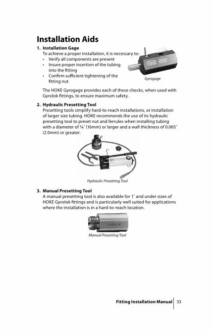
Installation Aids1. Installation Gage
To achieve a proper installation, it is necessary to:• Verify all components are present • Insure proper insertion of the tubing
into the fi tting• Confi rm suffi cient tightening of the
fi tting nut
The HOKE Gyrogage provides each of these checks, when used with Gyrolok fi ttings, to ensure maximum safety.
2. Hydraulic Presetting ToolPresetting tools simplify hard-to-reach installations, or installation of larger size tubing. HOKE recommends the use of its hydraulic presetting tool to preset nut and ferrules when installing tubing with a diameter of ⁄˝ (16mm) or larger and a wall thickness of 0.065˝ (2.0mm) or greater.
3. Manual Presetting ToolA manual presetting tool is also available for 1˝ and under sizes of HOKE Gyrolok fi ttings and is particularly well suited for applications where the installation is in a hard-to-reach location.
Gyrogage
Hydraulic Presetting Tool
Manual Presetting Tool

34 Fitting Installation Manual
4. Tube Stub AdaptersA tube stub adapter is an excellent tool to use when faced with pos-sible alignment problems. Consider the following situation.
• Situation: need to join tubing and female NPT port at 90° angle to one another
• Problem: with the NPT end properly assembled, the tube fi tting end of a male elbow may not properly line up with the tubing.
• Solution: Use a male tube stub adapter to convert the female port to a tube stub end.
• Assembly: Then simply use a union elbow to make the required connections.

Fitting Installation Manual 35
5. Port ConnectorsUse port connectors for close connecting one tube fi tting to anoth-er. Port connector installation is accomplished as follows:
• Remove nut and ferrules from fi rst port
• Firmly insert machined ferrule end of port connector into tube fi tting port
• Place nut over machined ferrule and fi nger tighten. Using wrench, turn nut until sharp rise in torque is felt, then simply snug.
• Insert tube stub end into tube fi tting port and follow initial assembly instructions to complete installation.

36 Fitting Installation Manual
6. Nut and Ferrule Safety ChangerA nut and ferrule safety changer provides the safest method of replacing fi tting components by eliminating the need for ferrule handling while ensuring proper ferrule orientation.
• To use a nut and ferrule safety changer, insert the changer end into the fi tting body, lightly thread the nut onto the body, and simply extract safety changer from nut
7. Bleed ValvesBleed valve nuts are crimped for safety. Loosen bleed valve nut to relieve system pressure. Never loosen the fi tting nut to relieve or bleed system pressure. Bleed fi ttings are specifi cally designed to perform this function.
Safety Changer
Bleed Union
Fitting Nuts
CapturedBleed Vent
Fitting Installation Manual 37
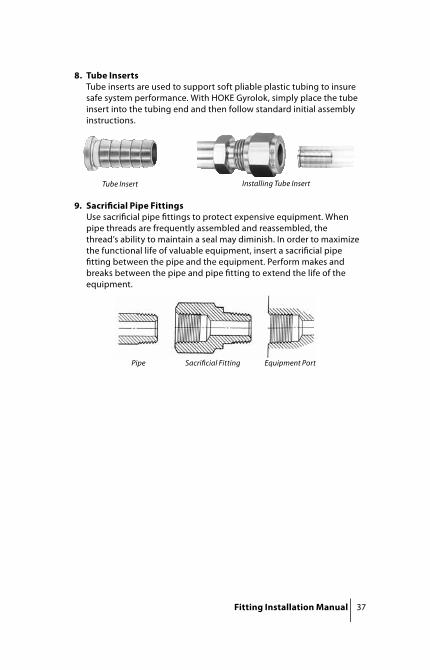
8. Tube InsertsTube inserts are used to support soft pliable plastic tubing to insure safe system performance. With HOKE Gyrolok, simply place the tube insert into the tubing end and then follow standard initial assembly instructions.
9. Sacrifi cial Pipe FittingsUse sacrifi cial pipe fi ttings to protect expensive equipment. When pipe threads are frequently assembled and reassembled, the thread’s ability to maintain a seal may diminish. In order to maximize the functional life of valuable equipment, insert a sacrifi cial pipe fi tting between the pipe and the equipment. Perform makes and breaks between the pipe and pipe fi tting to extend the life of the equipment.
Pipe Sacrifi cial Fitting Equipment Port
Tube Insert Installing Tube Insert

38 Fitting Installation Manual
HOKE Safety Check List1. Use products suitable for the application. HOKE Gyrolok fi ttings
provide outstanding protection against pressure/shock or vibration conditions.
2. Always use tubing that is compatible with the fi tting or valve material (e.g., use 316 stainless steel fi ttings with 316 stainless steel tubing). Tubing appropriate for use with HOKE products is described in the HOKE Tubing Data Charts.
3. Make sure the system is not pressurized when tightening or loosening a fi tting or valve connection.
4. When relieving or bleeding system pressure, do not loosen tube fi tting nut. Use appropriate bleed/relief device.
5. Do not exceed product temperature specifi cations.6. Do not exceed maximum allowable working pressure/temperature
combinations for tubing. Check the HOKE Tubing Data Charts for specifi c information when using HOKE Gyrolok fi ttings. If no pressure is identifi ed for a given size and wall thickness of tubing, that tubing is not considered suitable for use with HOKE Gyrolok. Note: that pressure ratings may vary for other fi tting ends. Contact HOKE for additional information.
7. When the application involves use of a toxic or hazardous fl uid, exercise extra caution during operation and maintenance.
8. Always leave a length of straight tube between the tube bend and the fi tting. A tube bent too close to the fi tting connection may be a source of leakage.
9. Before assembling new, unused HOKE Gyrolok tube fi tting ends, loosen the HOKE Gyrolok nut before inserting the tube to allow full insertion of the tube to the base of the body bore.
10. Use a Hydraulic Presetting Tool to preset nut and ferrules when installing tubing with a diameter of ⁄˝ (16mm) or larger and a wall thickness of 0.065˝ (2.0mm) or greater.
11. Use the HOKE Gyrogage, or other manufacturer’s installation tool, during fi tting assembly to ensure that key steps necessary to achieve proper makeup have been correctly performed.
12. In accordance with manufacturer’s instructions use a tube insert when assembling a tube fi tting to soft, pliable plastic tubing.
13. Use the HOKE Gyrolok Nut and Ferrule Safety Changer to ensure safe component replacement.
14. Always use proper thread lubricants or sealants on tapered pipe threads. Note that thread sealants may have diff erent temperature ratings than basic fi tting.
15. NPT threads should be torqued in accordance with an industry standard, such as Underwriter’s Laboratory UL842. Note that previously assembled threads may require additional tightening.

Fitting Installation Manual 39
16. For proper installation, request a Safety Installation Training Program today! Ask your HOKE distributor for details.
IT IS SOLELY THE RESPONSIBILITY OF THE SYSTEM DESIGNER AND USER TO SELECT PRODUCTS SUITABLE FOR THEIR SPECIFIC APPLICATION REQUIREMENTS AND TO ENSURE PROPER INSTALLATION, OPERATION, AND MAINTENANCE OF THESE PRODUCTS. MATERIAL COMPATIBILITY, PRODUCT RATINGS, AND APPLICATION DETAILS SHOULD BE CONSIDERED IN THE SELECTION.
Gyrolok® and Gyrogage® are registered trademarks of HOKE Incorporated.Monel® and Inconel® are registered trademarks of Special Metals Corporation.Hastelloy® is a registered trademark of Haynes International, Inc.
!

77100 • 10/04
Instrumentation
Technologies
CIR
COR
Instru
men
tation
Techn
olo
gies
405 Centura C
ourtSp
artanburg, SC
29303Tel (864) 574-7966Fax (864) 587-5608
CIR
COR
Instru
men
tation
, Ltd.
1-3 Bouverie RoadH
arrowM
iddlesex, HA
1 4HB
UK
Tel +44 (0) 20 8423 0113
Fax +44 (0) 20 8864 7008
ww
w.circor.co.uk
Circle Seal C
on
trols, In
c.2301 W
ardlow C
ircleC
orona, CA
92880Tel (951) 270-6200Fax (951) 270-6201
ww
w.circle-seal.com
CIR
COR
Tech405 C
entura Court
Spartanb
urg, SC 29303
Tel (864) 574-7966Fax (864) 587-5608
ww
w.circortech.com
GO
Reg
ulato
r405 C
entura Court
Spartanb
urg, SC 29303
Tel (864) 574-7966Fax (864) 587-5608
ww
w.goreg.com
HO
KE C
on
trols
1901 Lynx PlaceO
ntario, CA
91761Tel (909) 923-3770Fax (909) 923-2550
HO
KE, In
c.405 C
entura Court
Spartanb
urg, SC 29303
Tel (864) 574-7966Fax (864) 587-5608
ww
w.hoke.com
HO
KE G
mb
HW
eitzesweg 11
Postfach 15 41D
-61118 Bad Vilbel–D
ortelweil
Germ
anyTel +
49 6101 82 56 0Fax +
49 6101 82 56 40w
ww
.hoke.de
Panels P
lus
1901 Lynx PlaceO
ntario, CA
91761Tel (909) 923-3770Fax (909) 923-2550
ww
w.circor-panelsplus.com
TOM
CO405 C
entura Court
Spartanb
urg, SC 29303
Tel (864) 574-7966Fax (864) 587-5608
ww
w.tom
coquickcouplers.com


![TTINGS ULIC - Pagina di ingressodasa-it.com/files/raccordi idraulici [hydraulic fittings].pdf · TTINGS Gamma completa di raccordi idraulici ... SF6-XXXX SF6 SEMIFLANGIA SAE J518](https://img.pdfslide.us/doc/110x75/5a79836f7f8b9ade698c60b2/ttings-ulic-pagina-di-ingressodasa-itcomfilesraccordi-idraulici-hydraulic.jpg)