Embed Size (px)
Citation preview
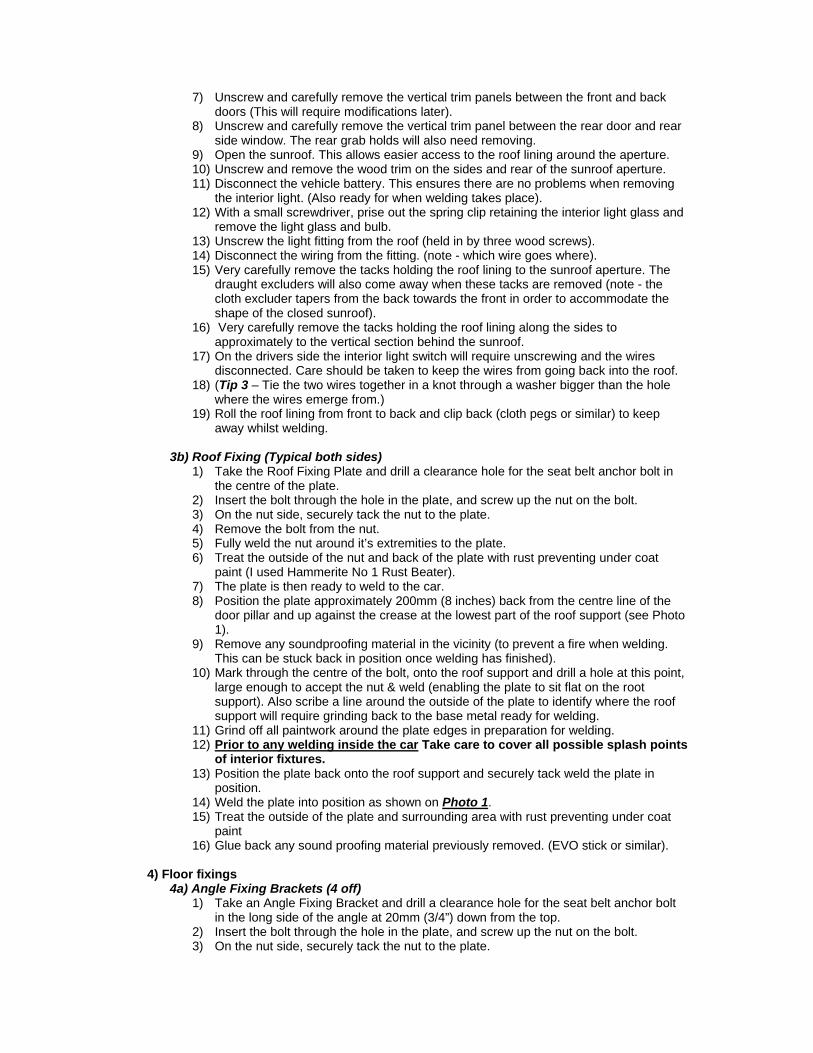
FITTING FRONT SEAT BELTS TO THE MG Y TYPE SALOON Background After much thought I decided to fit front seatbelts to my Y type during the body off restoration. There is an ongoing debate as to whether the belts should be fitted to the body or the chassis. It has been said that in a severe ‘head on’ accident the body may separate from the chassis and this could injure the person wearing the belt. However, most accidents occur at slower speeds and I was more concerned about these. As the Y type does not have air bags, collapsible steering column or laminated windscreen, I decided to fit seat belts to the front only as, most of the time, only two of us would be in the car. Also, having pondered over how the belts could be fitted only to the body I could not see a secure method of fitting the inner belt position (by the prop shaft) unless it was directly onto the chassis. Type of Belts Static belt types were chosen, due to the difficulty of mounting an inertia reel without restricting the rear seat passenger entrance into the vehicle. The reels of the inertia type have to be fitted vertically down from the roof fixing so the belt, when in use, would restrict the entrance into the rear seats. I used seat belts from Securon, part number 300/30 supplied by Stafford Vehicle Components Ltd. Tel: +44 (0) 1827 67714. (Price is £65 per pair + post & package). Remove the seat belt from the box and check which bolts & nuts are supplied. Some belts may only have the bolts, but may not have the nuts, as these are supplied for fitting to existing mounting points. Six nuts to suit the bolts will have to be sourced locally. I used some nuts from a previous set of belts. 1) New Items Required
a) Four (4) off 2mm (0.078”) thick mild steel brackets will require making to weld to the chassis. Two identical brackets for the inboard fixing point, made to Drawing 2 and one off each to Drawings 3 & 4 (these are the opposite hand of each other) for the outboard fixing point.
b) Also two (2) pieces of 2mm (0.078”) thick plate to Drawing 5 will be required to enable the third fixing point for the belts.
c) If the seat belts do not have angle bracket fixings, then four (4) off Angle fixing brackets will require manufacturing to the sizes on Drawing 6.
d) Two (2) pieces of rubber 3mm(0.125”) thick 90mm(3.5”) x 60mm(2.375”) for the chassis to body connection. See Photo 4 A local sheet metal supplier with bending and cutting machines should easily be able to supply these.
2) If fitting to a finished car. (If fitting during a body off restoration go to step 3b) below.) (Tip 1 – On removal ensure all bolts and screws are kept separately to ensure they go back in the same position, this can be done with a piece of cardboard with holes for the bolts) (Tip 2 – Purchase a copy of ‘Renewing the headlining on your Y type’ by Jack Murray from the Regalia section of the Y register site- well worth the money).
a) Remove both front seats. b) Remove all the carpets and under-felt.
3) Roof Fixing (Typical both sides)
3a) Dismantling 1) Wind the windscreen out fully, this is to help with the removal of headlining. 2) Unscrew and remove the rear view mirror and the wood finishing trim above the
windscreen aperture. 3) Unscrew and remove the both side woods to the windscreen aperture. 4) Carefully remove the trim and headlining (held in place by tacks) from the front
windscreen back to behind the rear door pillar and side window pillar. 5) Carefully prise off the front leather covered trim (held in place by tacks), over the
front doors. 6) Carefully prise off the rear leather covered trim (held in place by tacks), over the rear
doors.
7) Unscrew and carefully remove the vertical trim panels between the front and back doors (This will require modifications later).
8) Unscrew and carefully remove the vertical trim panel between the rear door and rear side window. The rear grab holds will also need removing.
9) Open the sunroof. This allows easier access to the roof lining around the aperture. 10) Unscrew and remove the wood trim on the sides and rear of the sunroof aperture. 11) Disconnect the vehicle battery. This ensures there are no problems when removing
the interior light. (Also ready for when welding takes place). 12) With a small screwdriver, prise out the spring clip retaining the interior light glass and
remove the light glass and bulb. 13) Unscrew the light fitting from the roof (held in by three wood screws). 14) Disconnect the wiring from the fitting. (note - which wire goes where). 15) Very carefully remove the tacks holding the roof lining to the sunroof aperture. The
draught excluders will also come away when these tacks are removed (note - the cloth excluder tapers from the back towards the front in order to accommodate the shape of the closed sunroof).
16) Very carefully remove the tacks holding the roof lining along the sides to approximately to the vertical section behind the sunroof.
17) On the drivers side the interior light switch will require unscrewing and the wires disconnected. Care should be taken to keep the wires from going back into the roof.
18) (Tip 3 – Tie the two wires together in a knot through a washer bigger than the hole where the wires emerge from.)
19) Roll the roof lining from front to back and clip back (cloth pegs or similar) to keep away whilst welding.
3b) Roof Fixing (Typical both sides)
1) Take the Roof Fixing Plate and drill a clearance hole for the seat belt anchor bolt in the centre of the plate.
2) Insert the bolt through the hole in the plate, and screw up the nut on the bolt. 3) On the nut side, securely tack the nut to the plate. 4) Remove the bolt from the nut. 5) Fully weld the nut around it’s extremities to the plate. 6) Treat the outside of the nut and back of the plate with rust preventing under coat
paint (I used Hammerite No 1 Rust Beater). 7) The plate is then ready to weld to the car. 8) Position the plate approximately 200mm (8 inches) back from the centre line of the
door pillar and up against the crease at the lowest part of the roof support (see Photo 1).
9) Remove any soundproofing material in the vicinity (to prevent a fire when welding. This can be stuck back in position once welding has finished).
10) Mark through the centre of the bolt, onto the roof support and drill a hole at this point, large enough to accept the nut & weld (enabling the plate to sit flat on the root support). Also scribe a line around the outside of the plate to identify where the roof support will require grinding back to the base metal ready for welding.
11) Grind off all paintwork around the plate edges in preparation for welding. 12) Prior to any welding inside the car Take care to cover all possible splash points
of interior fixtures. 13) Position the plate back onto the roof support and securely tack weld the plate in
position. 14) Weld the plate into position as shown on Photo 1. 15) Treat the outside of the plate and surrounding area with rust preventing under coat
paint 16) Glue back any sound proofing material previously removed. (EVO stick or similar).
4) Floor fixings
4a) Angle Fixing Brackets (4 off) 1) Take an Angle Fixing Bracket and drill a clearance hole for the seat belt anchor bolt
in the long side of the angle at 20mm (3/4”) down from the top. 2) Insert the bolt through the hole in the plate, and screw up the nut on the bolt. 3) On the nut side, securely tack the nut to the plate.
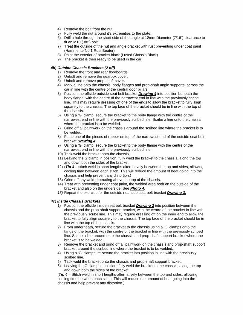
4) Remove the bolt from the nut. 5) Fully weld the nut around it’s extremities to the plate. 6) Drill a hole through the short side of the angle at 12mm Diameter (7/16”) clearance to
fit an M10 (3/8”) bolt. 7) Treat the outside of the nut and angle bracket with rust preventing under coat paint
(Hammerite No 1 Rust Beater) 8) Paint the exterior of bracket black (I used Chassis Black) 9) The bracket is then ready to be used in the car.
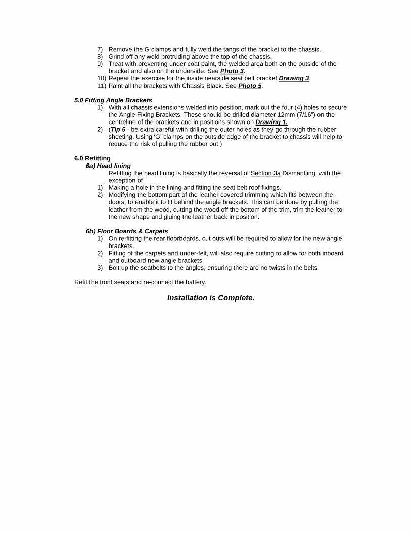
4b) Outside Chassis Brackets (2 off)
1) Remove the front and rear floorboards. 2) Unbolt and remove the gearbox cover. 3) Unbolt and remove prop-shaft cover. 4) Mark a line onto the chassis, body flanges and prop-shaft angle supports, across the
car in line with the centre of the central door pillars. 5) Position the offside outside seat belt bracket Drawing 4 into position beneath the
body flange, with the centre of the narrowest end in line with the previously scribe line. This may require dressing off one of the ends to allow the bracket to fully align squarely to the chassis. The top face of the bracket should be in line with the top of the chassis.
6) Using a ‘G’ clamp, secure the bracket to the body flange with the centre of the narrowest end in line with the previously scribed line. Scribe a line onto the chassis where the bracket is to be welded.
7) Grind off all paintwork on the chassis around the scribed line where the bracket is to be welded.
8) Place one of the pieces of rubber on top of the narrowest end of the outside seat belt bracket Drawing 4.
9) Using a ‘G’ clamp, secure the bracket to the body flange with the centre of the narrowest end in line with the previously scribed line.
10) Tack weld the bracket onto the chassis, 11) Leaving the G clamp in position, fully weld the bracket to the chassis, along the top
and down both the sides of the bracket. 12) (Tip 4 – stitch weld in short lengths alternatively between the top and sides, allowing
cooling time between each stitch. This will reduce the amount of heat going into the chassis and help prevent any distortion.)
13) Grind off any weld protruding above the top of the chassis. 14) Treat with preventing under coat paint, the welded area both on the outside of the
bracket and also on the underside. See Photo 4. 15) Repeat the exercise for the outside nearside seat belt bracket Drawing 3.
4c) Inside Chassis Brackets
1) Position the offside inside seat belt bracket Drawing 2 into position between the chassis and the prop-shaft support bracket, with the centre of the bracket in line with the previously scribe line. This may require dressing off on the inner end to allow the bracket to fully align squarely to the chassis. The top face of the bracket should be in line with the top of the chassis.
2) From underneath, secure the bracket to the chassis using a ‘G’ clamps onto the tangs of the bracket, with the centre of the bracket in line with the previously scribed line. Scribe a line around onto the chassis and prop-shaft support bracket where the bracket is to be welded.
3) Remove the bracket and grind off all paintwork on the chassis and prop-shaft support bracket around the scribed line where the bracket is to be welded.
4) Using a ‘G’ clamps, re-secure the bracket into position in line with the previously scribed line.
5) Tack weld the bracket onto the chassis and prop-shaft support bracket. 6) Leaving the G clamp in position, fully weld the bracket to the chassis, along the top
and down both the sides of the bracket. (Tip 4 – Stitch weld in short lengths alternatively between the top and sides, allowing cooling time between each stitch. This will reduce the amount of heat going into the chassis and help prevent any distortion.)
7) Remove the G clamps and fully weld the tangs of the bracket to the chassis. 8) Grind off any weld protruding above the top of the chassis. 9) Treat with preventing under coat paint, the welded area both on the outside of the
bracket and also on the underside. See Photo 3. 10) Repeat the exercise for the inside nearside seat belt bracket Drawing 3. 11) Paint all the brackets with Chassis Black. See Photo 5.
5.0 Fitting Angle Brackets
1) With all chassis extensions welded into position, mark out the four (4) holes to secure the Angle Fixing Brackets. These should be drilled diameter 12mm (7/16”) on the centreline of the brackets and in positions shown on Drawing 1.
2) (Tip 5 - be extra careful with drilling the outer holes as they go through the rubber sheeting. Using ‘G’ clamps on the outside edge of the bracket to chassis will help to reduce the risk of pulling the rubber out.)
6.0 Refitting
6a) Head lining Refitting the head lining is basically the reversal of Section 3a Dismantling, with the exception of
1) Making a hole in the lining and fitting the seat belt roof fixings. 2) Modifying the bottom part of the leather covered trimming which fits between the
doors, to enable it to fit behind the angle brackets. This can be done by pulling the leather from the wood, cutting the wood off the bottom of the trim, trim the leather to the new shape and gluing the leather back in position.
6b) Floor Boards & Carpets
1) On re-fitting the rear floorboards, cut outs will be required to allow for the new angle brackets.
2) Fitting of the carpets and under-felt, will also require cutting to allow for both inboard and outboard new angle brackets.
3) Bolt up the seatbelts to the angles, ensuring there are no twists in the belts. Refit the front seats and re-connect the battery.
Installation is Complete.
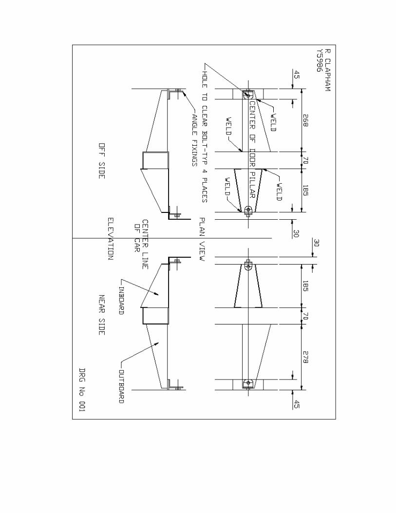
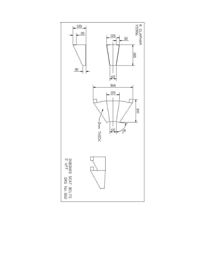
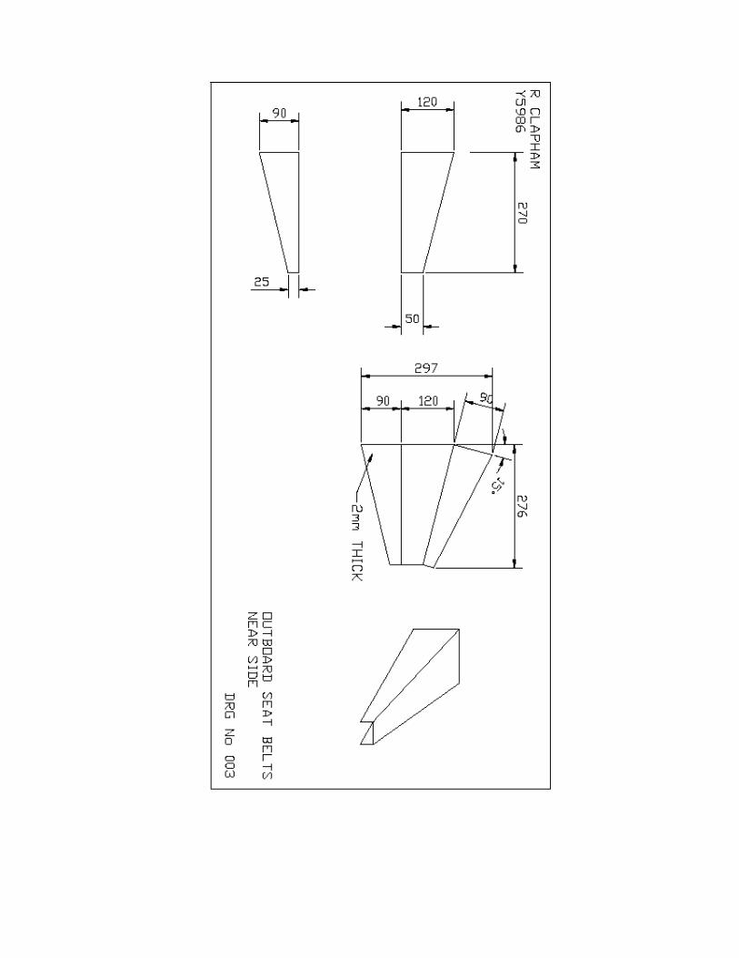
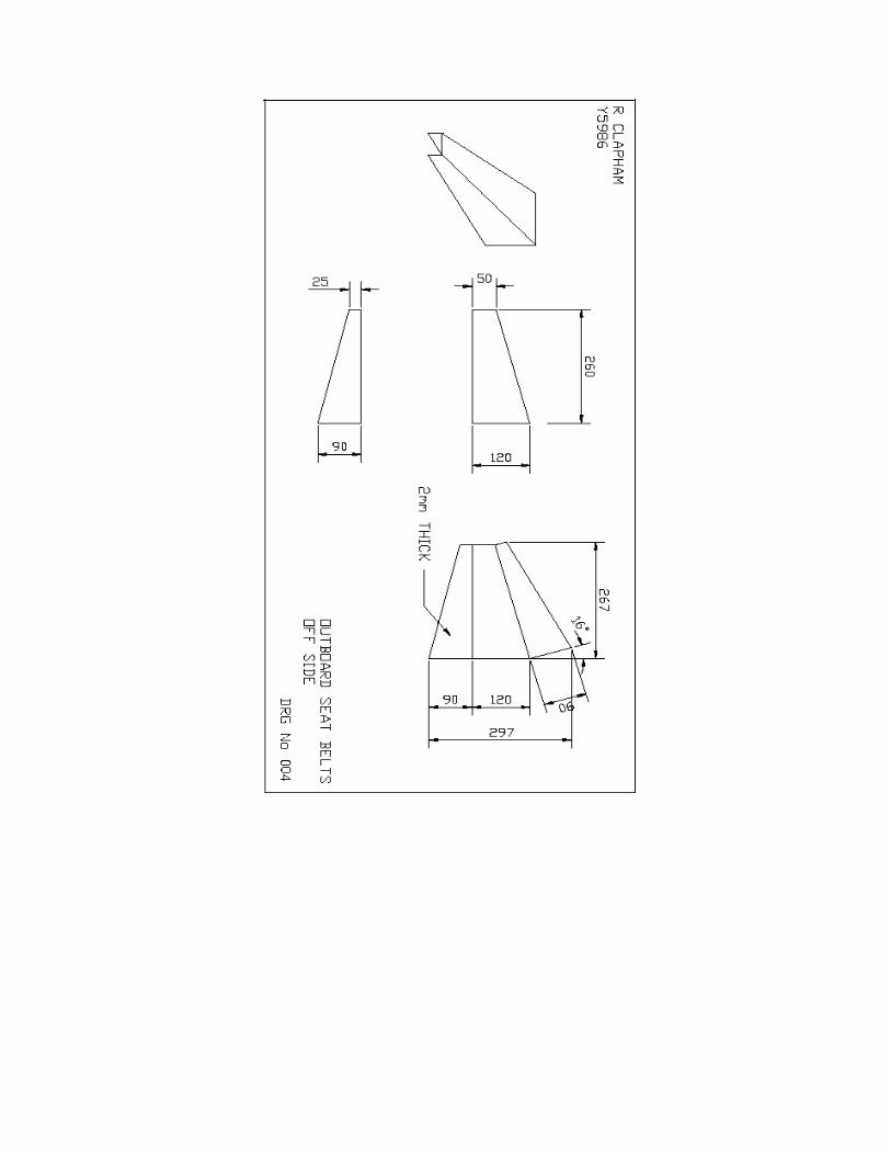
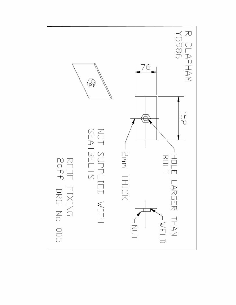
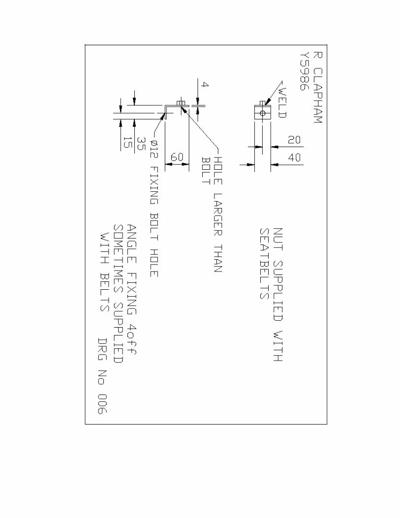
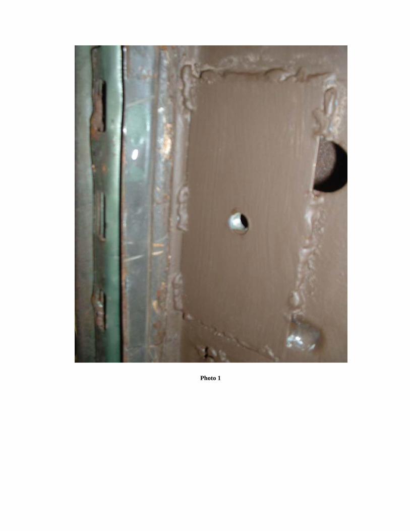
Photo 1
Photo 2
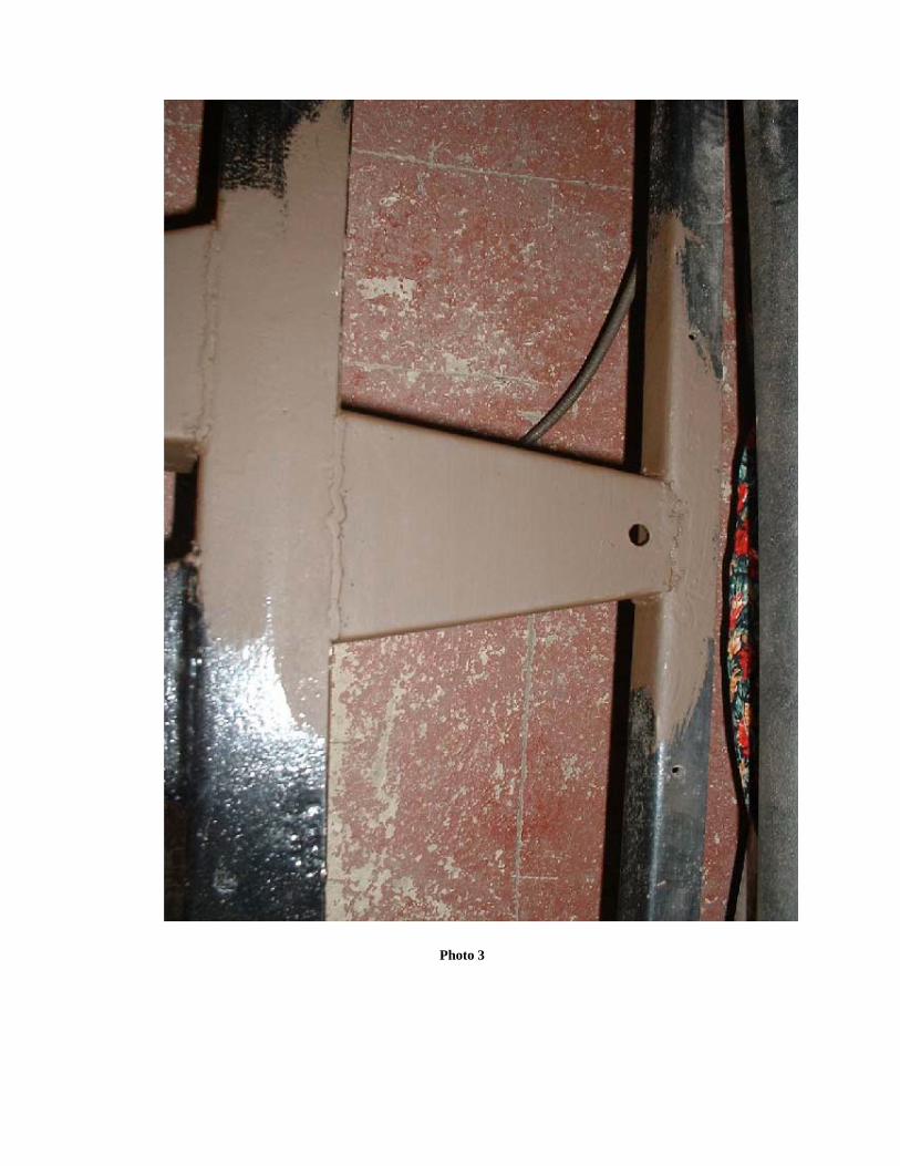
Photo 3
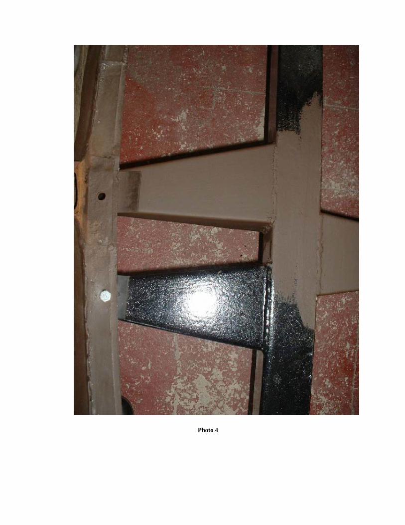
Photo 4
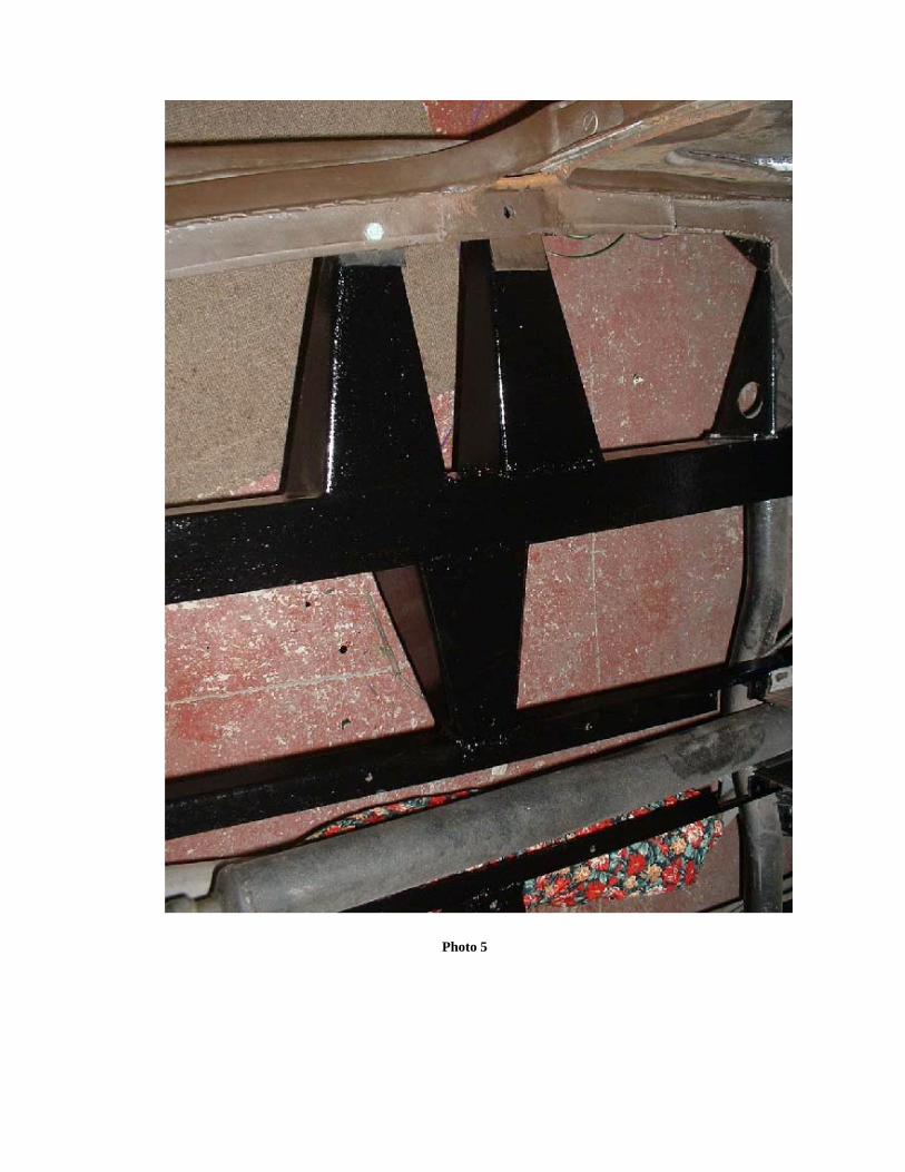
Photo 5