Embed Size (px)
Citation preview

8/12/2019 Fitting 2SC5707 in Dell monitors.pdf
http://slidepdf.com/reader/full/fitting-2sc5707-in-dell-monitorspdf 1/8
Fitting 2SC5707 in Dell monitors (Benq Chassis)
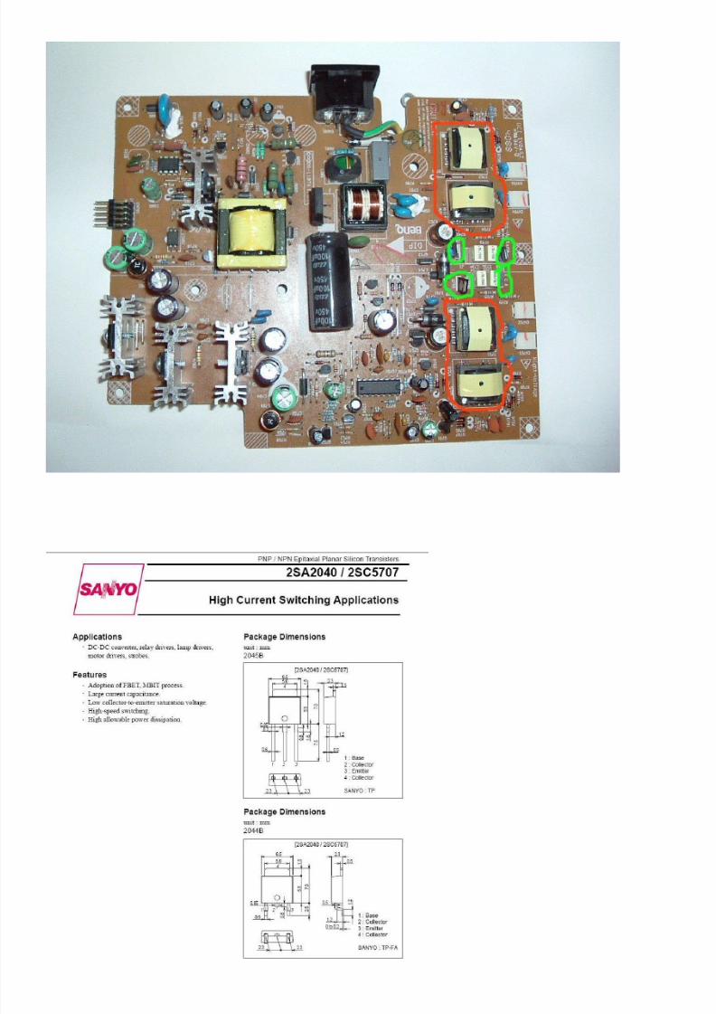
One of the most common failures in the Dell E172FPB are the backlight inverter transistors. The symptoms are either the display appears for a second then goes off or no display and the power light flashes.
There are 4 transistors used in the backlight inverters, 2 per pair of tubes. (Circled in green)They MUST be changed in pairs. If you are not sure how to test transistors then I suggest you change all 4. Note the orientation. Pair one is the opposite way around to pair 2
Also it is imperative that ALL the legs on the inverter transformers (circled in red) MUST be re-soldered even if they look ok. Failure to do this WILL result in dead transistors after a short time.
The 2SC5707 will also replace the 2SC5706This chassis will also be found in other makes and models.
8/12/2019 Fitting 2SC5707 in Dell monitors.pdf
http://slidepdf.com/reader/full/fitting-2sc5707-in-dell-monitorspdf 2/8
8/12/2019 Fitting 2SC5707 in Dell monitors.pdf
http://slidepdf.com/reader/full/fitting-2sc5707-in-dell-monitorspdf 3/8
8/12/2019 Fitting 2SC5707 in Dell monitors.pdf
http://slidepdf.com/reader/full/fitting-2sc5707-in-dell-monitorspdf 4/8
8/12/2019 Fitting 2SC5707 in Dell monitors.pdf
http://slidepdf.com/reader/full/fitting-2sc5707-in-dell-monitorspdf 5/8
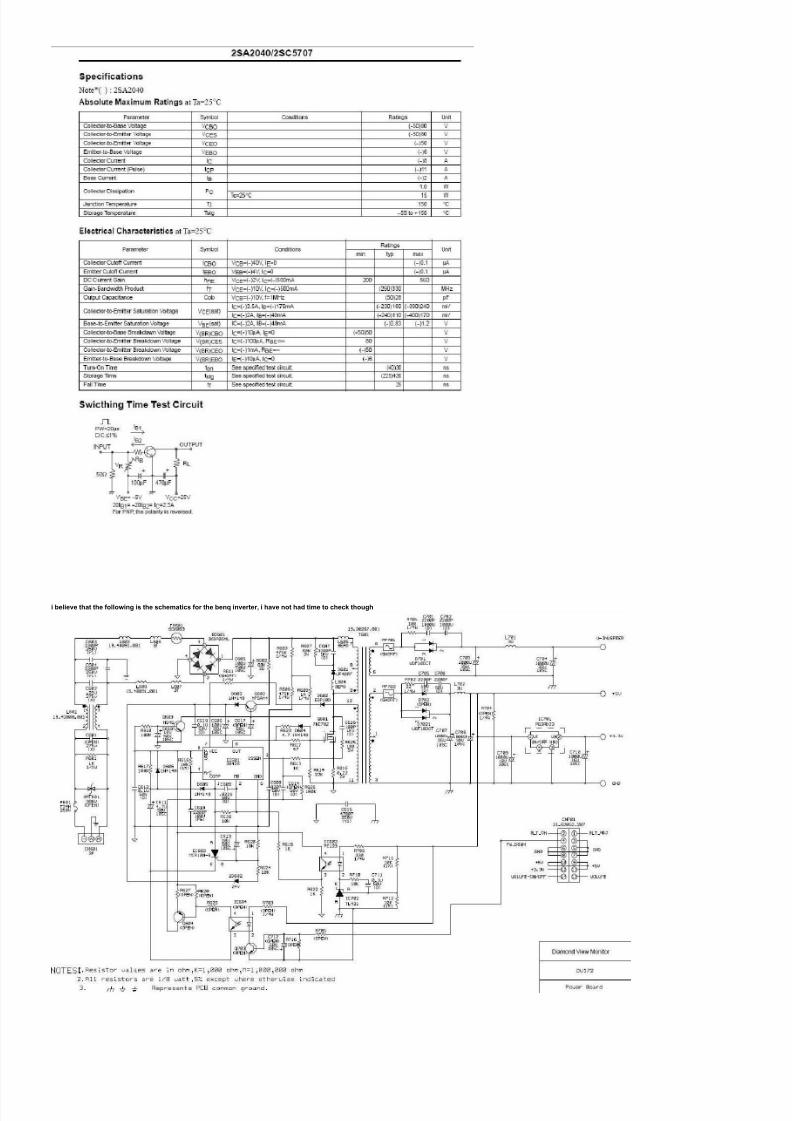
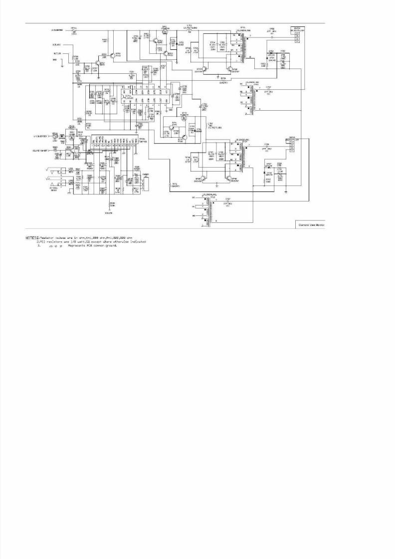
i believe that the following is the schematics for the benq inverter, i have not had time to check though

8/12/2019 Fitting 2SC5707 in Dell monitors.pdf
http://slidepdf.com/reader/full/fitting-2sc5707-in-dell-monitorspdf 6/8

8/12/2019 Fitting 2SC5707 in Dell monitors.pdf
http://slidepdf.com/reader/full/fitting-2sc5707-in-dell-monitorspdf 7/8
and a write-up from a forum that ma y help,
I am an Electrical Engineering student and purchased this monitor broken because I’m cheap… and well, I’m learning how to design these things. I have curiously been following this thread and finally decided to contribute. I hopefully this may shed somelight on thing or two… or possibly confuse some. To my knowledge the following ispretty accurate… I tried to simplify the operational aspect to the best of my ability w/o going too overboard. SoThis is for those who have had no success after replacing/testing Q759 Q760 Q739 Q740(2SC5707), and the inverter transformers T752 T754 T753 T751 (type: 9.5uH EE19).{In order to test the transformers you’ll need to use a ringer and or a Henry meter, most
electronic repair shops have the ability to test these components using a componentanalyzer}. Ideally shorts in these components result in IC751 detecting the “short” or “open” (or just a bad lamp) and shutting down the PWM in order prevent further damage. Keep in mind there are two separate but identical inverter circuits driving two CCLFoutputs.
Also, when testing components such as transistors, capacitors, resistors, etc… Desolder them and test them separate from the circuit. Tip; if you are testing a two terminal device(i.e. resistor) you only need to remove one leg of the device before testing.The key component of this inverter circuit is IC751 (TL1451AC) a PWM dual powersupply control… For those unfamiliar with PWM; PWM is when a voltage or current source is supplied to an analog load by means of a repeating series of on and off pulses.The on-time is the time during which the DC supply is applied to the load, and the off timeis the period during which that supply is switched off. A feedback is provided fromthe output in order maintain a specified voltage and frequency by varying the on -timeand off-times.---Anyway, IC751 pulses Q751 or Q743 which act as electronic switches(small amount of power to control the flow of a large amount of current). The Pulsedsignal is then fed into an inverter circuit i.e. Q759 Q760 or Q739 Q740… (Basically eachset compose a push-pull circuit) which is tied to two paralleled transformers boosting the
Voltage to around 600Vrms in order to fire the CCFL lamps. Feedback from CCFLlamps is provided via D753 D764 R762 and D767 D758 R742 respectively (**veryimportant** - a faulty component in this section will overdrive the output i.e. Q759…). The figure/diagram below shows the type of configuration in this board (Royer circuit). – {Feedback Diodes are 1N4148’s} Basically, IC751 contains an oscillator circuit in whose’ frequency is controlled by C765 (470p 50v) and R765 (10K 1%). ***(these values are critical for proper operation of theoscillator circuitry)*** If the values of C765 and/or R756 drift out of tolerance. Thefrequency of the circuit will exponentially change. This is of particular importance whenselecting a replacement transistor Q759 Q760… check the frequency band-width, also afast switching transistor type is a must. When dealing with frequency in the 50 – 100+KHz range internal resistance and capacitances can cause excessive Vce leakagetherefore causing increased heat dissipation (eventually leading to thermalrunaway…voltage punch-thru). Check these things; C765 and R765, which control theoscillator frequency oscillator and may be the reason f or many of the “HOT” Q759 Q760//Q739 Q740 transistors??? {The tables below were obtained from the componentdata-sheet showing the effects of changing Ct~C765 and Rt~R765}I have read that some of you are checking voltage across D751 or D761… This is a bad point to accurately check the circuit unless you are checking with an Oscilloscope. Atypical voltmeter has a relatively low impedance… meaning anything above the 1 KHz range is will not be a valid measurement. At this point is a high frequency pulse widthmodulated (PWM) signal, not a typical AC sinusoidal voltage. “Ok”, well if you see voltage across both… this means that a PWM signal driving the notoriously failing 2SC5707 tranny’s; Q759 Q760//Q739 Q740. However, if you want to check voltage; measure ac ross IC751 pin’s 8~ (ground) and 9~ (+15Vdc) there should be 15Vdc. If there is NOT voltage check Q761 (p-type bipolartransistor A733)… {Q761 regulates the DC voltage to IC751 via biasing resistors R752 R754 and “turn on” transistor Q757}. If there IS +15Vdc, check/replace Q751 Q743 and IC751… Q751//Q643 are MOS type, they are the “switch” which induce the PWM voltage into the transformers by injecting Q759 Q760//Q739 Q740 respectively.

8/12/2019 Fitting 2SC5707 in Dell monitors.pdf
http://slidepdf.com/reader/full/fitting-2sc5707-in-dell-monitorspdf 8/8
Also, test/check/ (replace if unsure): C764 (1uF 50v #105C), C754 C755 C734C735 (all .15uF 250V MKP type), R768 R769 R748 R749 (all 1Kohm 1/2w),D761 D761 (SB360 schottky diode), C771 C772 (220pF 50V)…THE FOLLOWING IS ONLY IF YOUR MONITOR IS COMPLETELY ”DEAD” no LED light ON indication flash etc… (Assuming you’ve checked the fuse) Check for voltage on IC601 (3842B) pins 5-gnd 7-Vcc; If there is voltage; test/replace Q603 (n-type bjt H945) Q602 (n-typeMPSA44) R602 (68Kohm 2w) and IC601.If there is NO voltage on IC601… replace optical isolator IC602 (PC123F1), and check/replace IC702 (TL431) and D701 (UGF10DCT).The following is a schematic from a very similar model Benq Inverter Circuit… Something that I find interesting is that on my board is a 100uF 25v c ap for C772however a 22uF 50v (#105C), is on this boards schematic for an LG monitor… Interestingly this capacitor determines the protection enable time characteristicsfor the inverter limiting an over current condition. (Graph was taken from IC751’s datasheet).