Embed Size (px)
Citation preview
Fitted with a main pressure relief valve and a load check valve on every
working section.
Available with parallel circuit.
Optional carry-over
Variety of port valves (auxiliary valves)
Available manual, pneumatic, and hydraulic spool control kits.
2
This catalogue shows technical specifications and diagrams measured with mineral oil of 32 mm2/s –
32 cSt at 40 oC – 104
oF temperature.
Nominal flow rating 160 l/min 42 US gpm
Operating pressure (max.) 315 bar 4600 psi
Back pressure (max.) outlet port T 25 bar 360 psi
Internal leakage
(max.) A(B)→T
Δp = 100 bar (1450 psi)
fluid and valve at 40 oC
(104 oF)
15 cm3/min 0.91 in
3/min
Fluid Mineral based oil
Fluid temperature with NBR from -20
oC to 80
oC from -4
oF to 176
oF
with FPM from -20 oC to 100
oC from -4
oF to 212
oF
Viscosity
operating range from 15 to 75 mm2/s from 15 to 75 cSt
min. 12 mm2/s 12 cSt
max. 400 mm2/s 400 cSt
Max contamination level -/19/16 - ISO 4406 NAS 1683 - class 10
Ambient temperature
for working
conditions
with mechanical devices from -40 oC to 60
oC from -40
oF to 140
oF
with pneumatic and
hydraulic devices from -30
oC to 60
oC from -22
oF to 140
oF
with electric devices from -20 oC to 50
oC from -4
oF to 122
oF
Note – for different conditions please contact Sales department
Reference standard
BSP UN-UNF NPTF
THREAD ACCORDING TO ISO 228/1 ISO 263
ANSI B1.20.3 BS 2779 ANSI B1.1 unified
CAVITY DIMENSION
ACCORDING TO
ISO 1179 11926-1
SAE
J1926-1 J476a
DIN 3852-2
Ports
BSP UN-UNF
Order code G34 G1 SAE
Inlet P G 3/4 G 1 1 5/16-12 (SAE16)
Ports A and B G 3/4 1 1/16-12 (SAE12)
Outlet T and carry-over C G 1 1 5/16-12 (SAE16)
Hydraulic pilots G 1/4 9/16-18 (SAE6)
Pneumatic pilots NPTF 1/8-27
3
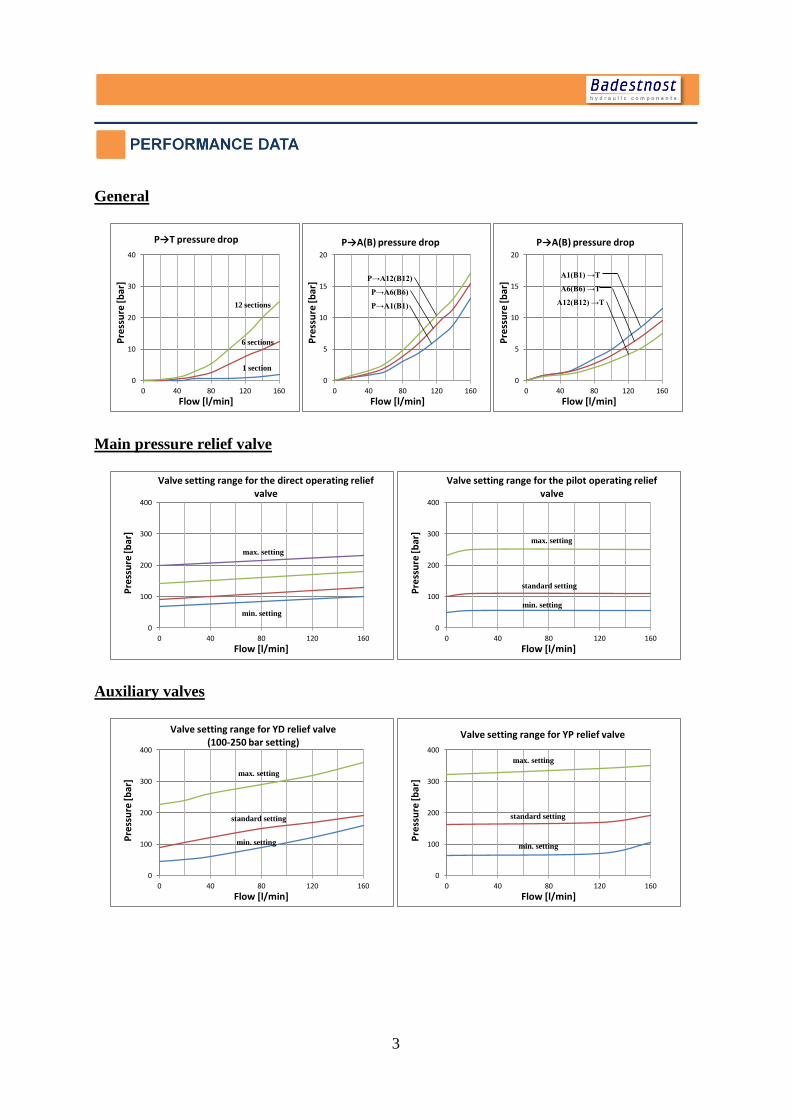
General
Main pressure relief valve
Auxiliary valves
0
10
20
30
40
0 40 80 120 160
Pre
ssu
re [b
ar]
Flow [l/min]
P→T pressure drop
1 section
6 sections
12 sections
0
5
10
15
20
0 40 80 120 160
Pre
ssu
re [b
ar]
Flow [l/min]
P→A(B) pressure drop
P→A12(B12)
P→A6(B6)
P→A1(B1)
0
5
10
15
20
0 40 80 120 160
Pre
ssu
re [b
ar]
Flow [l/min]
P→A(B) pressure drop
A1(B1) →T
A6(B6) →T
A12(B12) →T
0
100
200
300
400
0 40 80 120 160
Pre
ssu
re [b
ar]
Flow [l/min]
Valve setting range for the direct operating relief valve
min. setting
max. setting
0
100
200
300
400
0 40 80 120 160
Pre
ssu
re [b
ar]
Flow [l/min]
Valve setting range for the pilot operating relief valve
min. setting
standard setting
max. setting
0
100
200
300
400
0 40 80 120 160
Pre
ssu
re [b
ar]
Flow [l/min]
Valve setting range for YD relief valve (100-250 bar setting)
min. setting
standard setting
max. setting
0
100
200
300
400
0 40 80 120 160
Pre
ssu
re [b
ar]
Flow [l/min]
Valve setting range for YP relief valve
min. setting
standard setting
max. setting
4
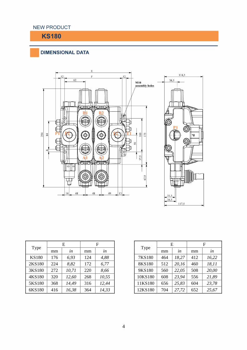
Type E F
Type E F
mm in mm in
mm in mm in
KS180 176 6,93 124 4,88
7KS180 464 18,27 412 16,22
2KS180 224 8,82 172 6,77
8KS180 512 20,16 460 18,11
3KS180 272 10,71 220 8,66
9KS180 560 22,05 508 20,00
4KS180 320 12,60 268 10,55
10KS180 608 23,94 556 21,89
5KS180 368 14,49 316 12,44
11KS180 656 25,83 604 23,78
6KS180 416 16,38 364 14,33
12KS180 704 27,72 652 25,67
5
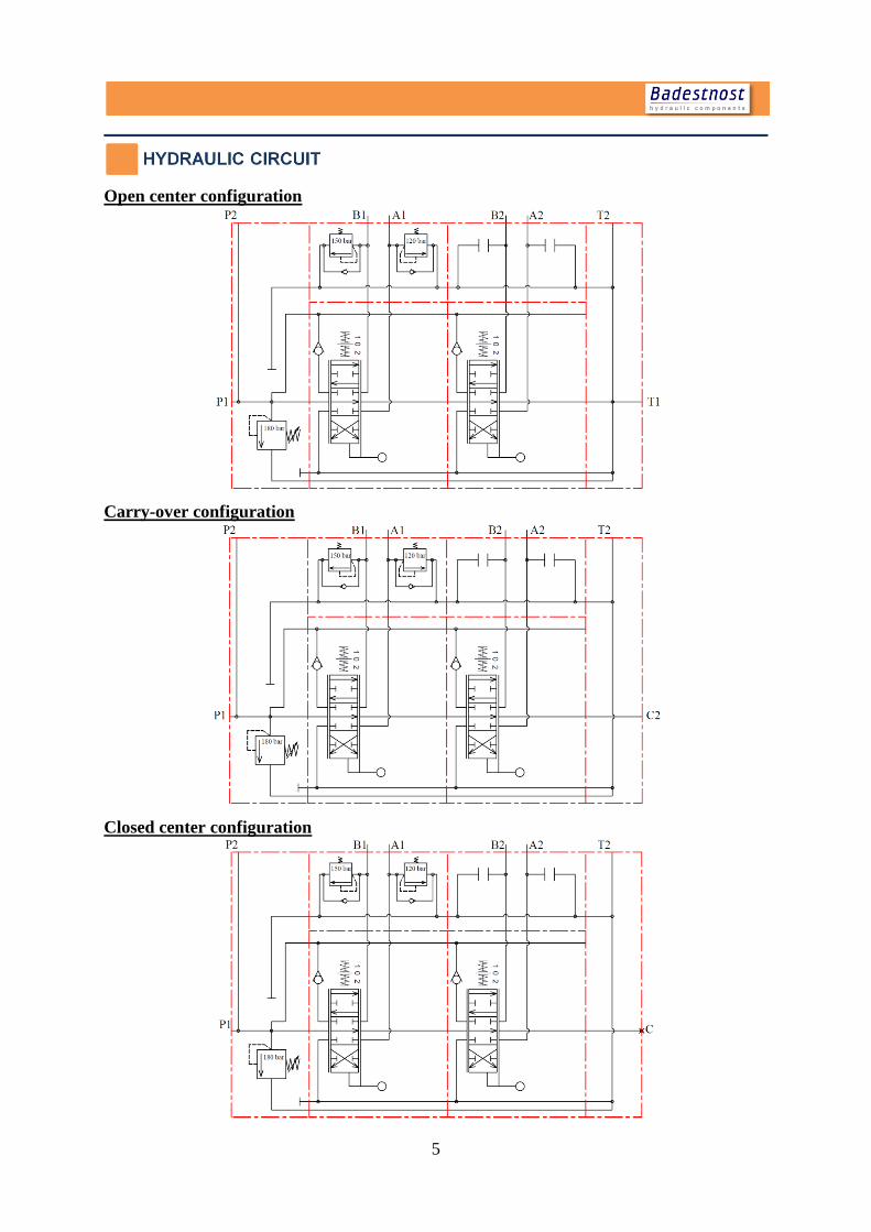
Open center configuration
Carry-over configuration
Closed center configuration
6
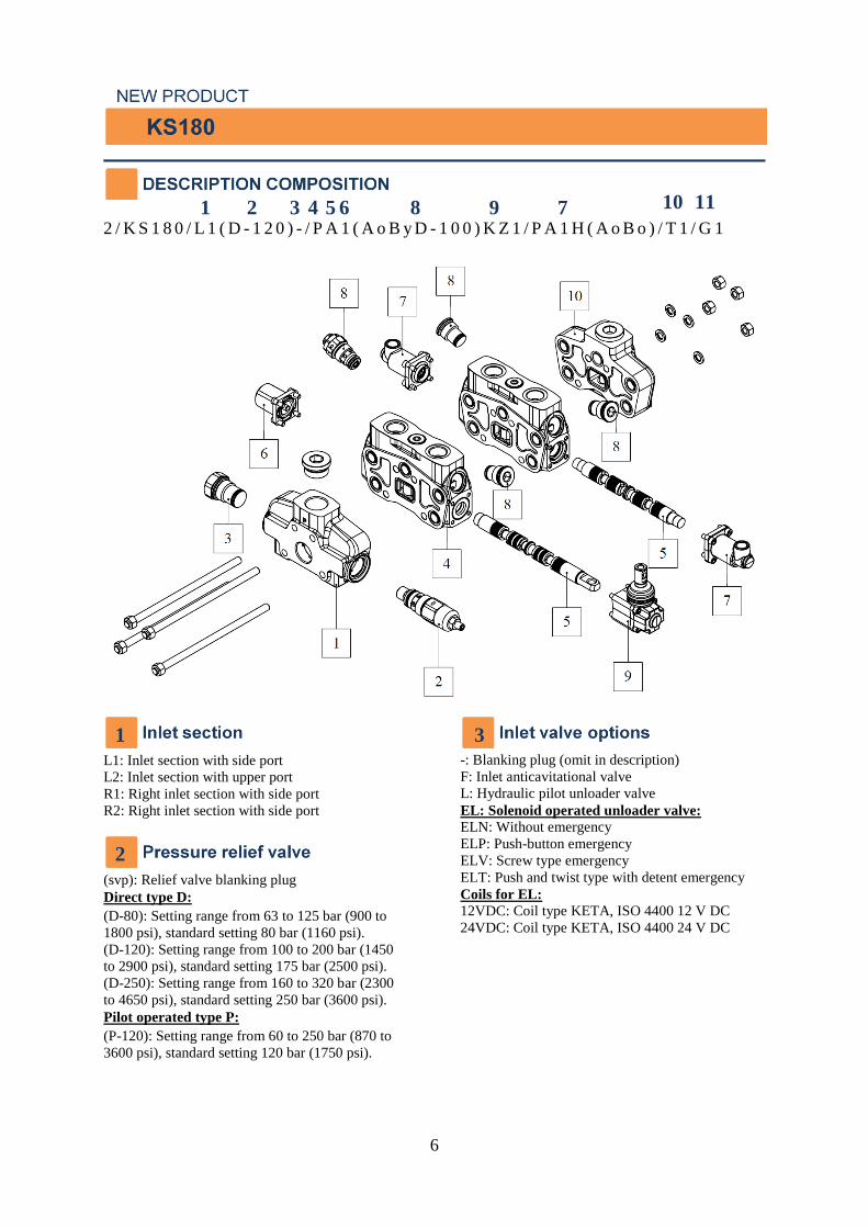
2 / K S 1 8 0 / L 1 ( D - 1 2 0 ) - / P A 1 ( A o B y D - 1 0 0 ) K Z 1 / P A 1 H ( A o B o ) / T 1 / G 1
L1: Inlet section with side port
L2: Inlet section with upper port
R1: Right inlet section with side port
R2: Right inlet section with side port
(svp): Relief valve blanking plug
Direct type D:
(D-80): Setting range from 63 to 125 bar (900 to
1800 psi), standard setting 80 bar (1160 psi).
(D-120): Setting range from 100 to 200 bar (1450
to 2900 psi), standard setting 175 bar (2500 psi).
(D-250): Setting range from 160 to 320 bar (2300
to 4650 psi), standard setting 250 bar (3600 psi).
Pilot operated type P:
(P-120): Setting range from 60 to 250 bar (870 to
3600 psi), standard setting 120 bar (1750 psi).
-: Blanking plug (omit in description)
F: Inlet anticavitational valve
L: Hydraulic pilot unloader valve
EL: Solenoid operated unloader valve:
ELN: Without emergency
ELP: Push-button emergency
ELV: Screw type emergency
ELT: Push and twist type with detent emergency
Coils for EL:
12VDC: Coil type KETA, ISO 4400 12 V DC
24VDC: Coil type KETA, ISO 4400 24 V DC
1
2
3
1 2 3 4 5
6
6 9 8 7 10 11
7
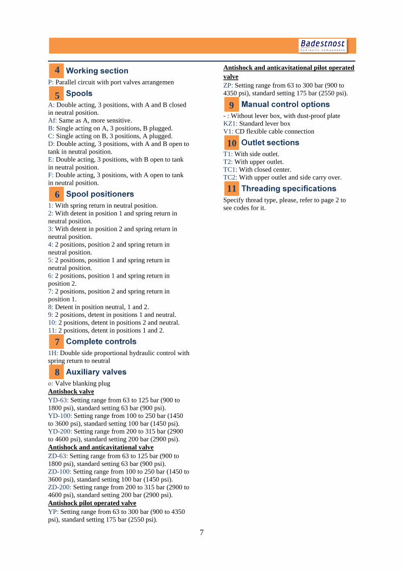
P: Parallel circuit with port valves arrangemen
A: Double acting, 3 positions, with A and B closed
in neutral position.
Af: Same as A, more sensitive.
B: Single acting on A, 3 positions, B plugged.
C: Single acting on B, 3 positions, A plugged.
D: Double acting, 3 positions, with A and B open to
tank in neutral position.
E: Double acting, 3 positions, with B open to tank
in neutral position.
F: Double acting, 3 positions, with A open to tank
in neutral position.
1: With spring return in neutral position.
2: With detent in position 1 and spring return in
neutral position.
3: With detent in position 2 and spring return in
neutral position.
4: 2 positions, position 2 and spring return in
neutral position.
5: 2 positions, position 1 and spring return in
neutral position.
6: 2 positions, position 1 and spring return in
position 2.
7: 2 positions, position 2 and spring return in
position 1.
8: Detent in position neutral, 1 and 2.
9: 2 positions, detent in positions 1 and neutral.
10: 2 positions, detent in positions 2 and neutral.
11: 2 positions, detent in positions 1 and 2.
1H: Double side proportional hydraulic control with
spring return to neutral
о: Valve blanking plug
Antishock valve
YD-63: Setting range from 63 to 125 bar (900 to
1800 psi), standard setting 63 bar (900 psi).
YD-100: Setting range from 100 to 250 bar (1450
to 3600 psi), standard setting 100 bar (1450 psi).
YD-200: Setting range from 200 to 315 bar (2900
to 4600 psi), standard setting 200 bar (2900 psi).
Antishock and anticavitational valve
ZD-63: Setting range from 63 to 125 bar (900 to
1800 psi), standard setting 63 bar (900 psi).
ZD-100: Setting range from 100 to 250 bar (1450 to
3600 psi), standard setting 100 bar (1450 psi).
ZD-200: Setting range from 200 to 315 bar (2900 to
4600 psi), standard setting 200 bar (2900 psi).
Antishock pilot operated valve
YP: Setting range from 63 to 300 bar (900 to 4350
psi), standard setting 175 bar (2550 psi).
Antishock and anticavitational pilot operated
valve
ZP: Setting range from 63 to 300 bar (900 to
4350 psi), standard setting 175 bar (2550 psi).
- : Without lever box, with dust-proof plate
KZ1: Standard lever box
V1: CD flexible cable connection
T1: With side outlet.
T2: With upper outlet.
TC1: With closed center.
TC2: With upper outlet and side carry over.
Specify thread type, please, refer to page 2 to
see codes for it.
8
9
4
5
6
7
10
11