Embed Size (px)
Citation preview

www.infotech.monash.edu.au/FIT1004/
FIT1004 DatabaseTopic 2: Database Design Life Cycle
Learning Objectives:• Describe the 3 level ANSI SPARC Database Architecture and the advantages
which its inherent data abstraction provide to the database developer• Explain the role of database development within an information system• Describe the steps involved in the Systems Development Life Cycle (SDLC)• Explain the steps involved in the Database Life Cycle (DBLC) • Explain, in detail, within the Database Design phase of the DBLC, the role of:
ER modelling and Normalisation, Data Model Verification, Distributed Database Design, Logical and Physical Design
• Describe the database design strategies - Top-down vs. bottom-up design and Centralised vs. decentralised design
Reference:• Rob, P., & Coronel, C. (2004) Database Systems: Design, Implementation &
Management (6th Edition), Chapter 2 Section 2.5, Chapter 8. • Rob, P., & Coronel, C. (2007) Database Systems: Design, Implementation &
Management (7th Edition), Chapter 2 Section 2.5, Chapter 9.

2
Where We Are
Introduction to Database Systems The Relational Model
Conceptual Design Logical Design Normalisation
Database Lifecycle Physical Design
SQL (DML) SQL (DDL & DCL) Implementation Transaction Management
Database Administration
Data Warehousing & Data Mining

3
3 Level ANSI-SPARC Database Architecture
• ANSI/SPARC– classified data models in the 1970s according to their degree of
abstraction: conceptual, external and internal• System requirements
– All users should be able to access same data– A user's view should be immune to changes made in other views– Users should not need to know physical database storage details– Database Administrator (DBA) should be able to change database
storage structures without affecting the users' views.– Internal structure of database should be unaffected by changes to
physical aspects of storage.– DBA should be able to change conceptual structure of database
without affecting all users
4
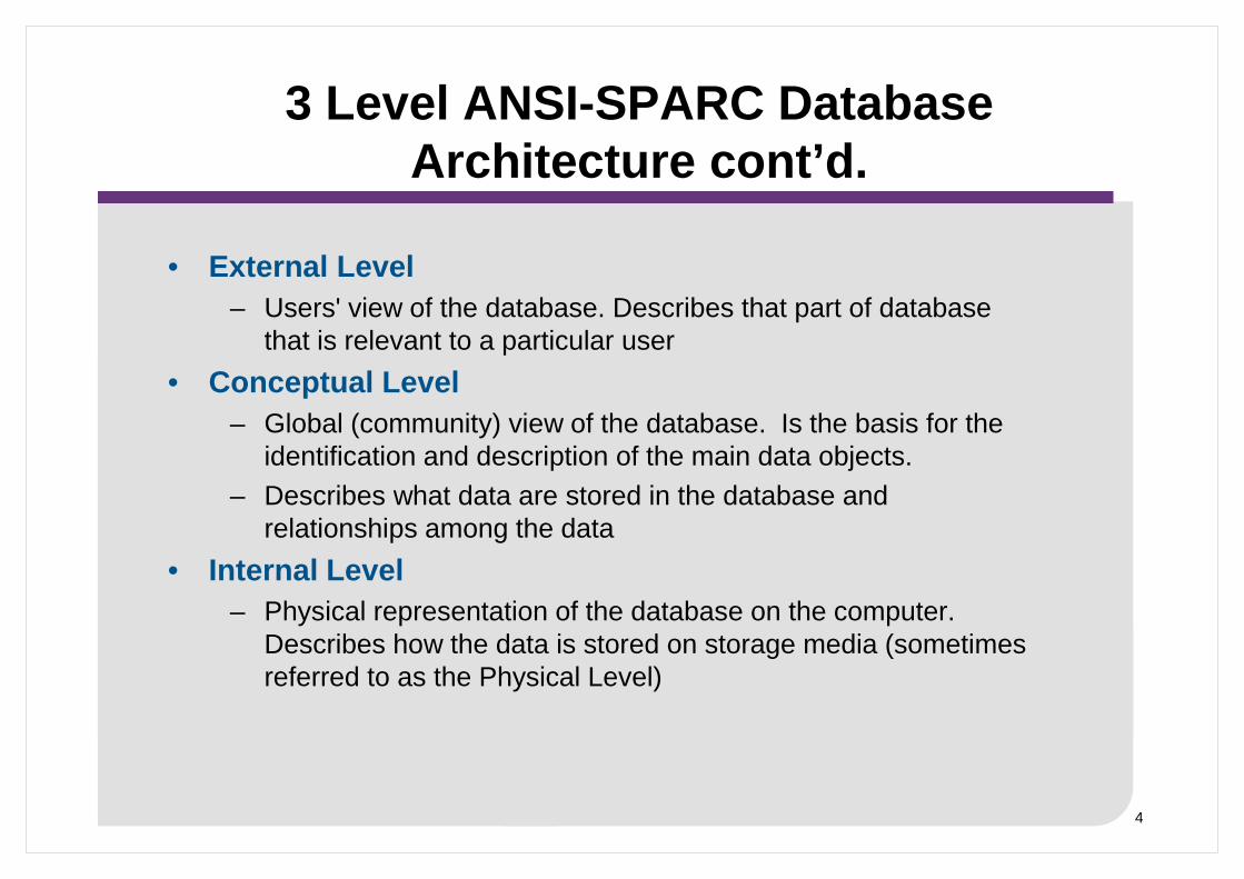
3 Level ANSI-SPARC Database Architecture cont’d.
• External Level– Users' view of the database. Describes that part of database
that is relevant to a particular user• Conceptual Level
– Global (community) view of the database. Is the basis for the identification and description of the main data objects.
– Describes what data are stored in the database and relationships among the data
• Internal Level– Physical representation of the database on the computer.
Describes how the data is stored on storage media (sometimes referred to as the Physical Level)

5
3 Level ANSI-SPARC Database Architecture
6
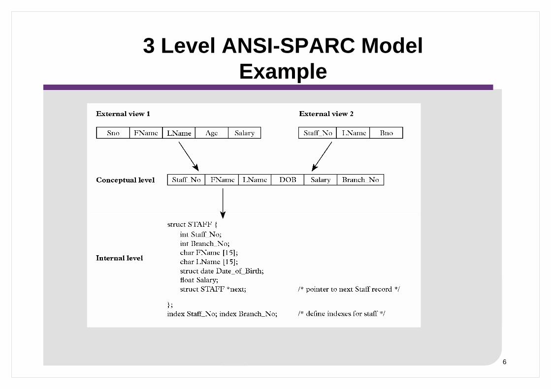
3 Level ANSI-SPARC ModelExample

7
3 Level ANSI-SPARC Model Independence
• Logical Data Independence– Refers to immunity of external schemas to changes
in conceptual schema– Conceptual schema changes e.g. addition/removal
of entities> Should not require changes to external schema or
rewrites of application programs

8
• Physical Data Independence– Refers to immunity of conceptual schema to
changes in the internal schema– Internal schema changes e.g. using different file
organisations, storage structures/devices> Should not require change to conceptual or external
schemas
3 Level ANSI-SPARC Model Independence

9
3 Level ANSI-SPARC Model Independence

10
Conceptual Level Representation - as an ERD
Entity RelationshipDiagram

11
Conceptual Level Representation – as a DSD
Extended Bachman DiagramorData Structure Diagram

12
Conceptual Level Representation – as a DBMS Schema
CREATE TABLE CUSTOMER (cust_no NUMBER(5) NOT NULL,cust_family CHAR(20) NOT NULL,cust_given CHAR(20) NOT NULL,cust_street CHAR(20) NOT NULL,cust_town CHAR(20) NOT NULL,cust_postcode CHAR(4) NOT NULL,cust_phone CHAR(10),
CONSTRAINT pk_CUSTOMER PRIMARY KEY (cust_no));…etc One ‘create table’ for each ‘box’ on the DSD

13
Changing Data into Information
• Data – Raw facts stored in databases– Need additional processing to become useful
• Information– Data processed and presented in a meaningful form– Can be as simple as tabulating the data, thereby
making certain data patterns more obvious• Transformation
– Any process that changes data into information

14
Changing Data into InformationAn example

15
The Information System and its applications
• Information System– Provides for data collection, storage, and retrieval– Composed of people, hardware, software,
database(s), application programs, and procedures– Systems analysis
> Process that establishes need for and extent of an information system
– Systems development> Process of creating an information system

16
The Information System and its applications cont’d
• Applications– Transform data into information that forms the basis
for decision making– Usually produce
> Formal reports, Tabulations, Graphic displays– Composed of two parts
> Data > Code by which the data are transformed into
information

17
Generating Information for Decision Making

18
The Systems Development Life Cycle (SDLC)

19
The Database Life Cycle (DBLC)

20
Phase 1: The Database Initial Study
• Overall purpose:– Analyse the company situation
> Discover what the company’s operational components are, how they function, and how they interact
– Define problems and constraints– Define objectives
> Defines extent of design according to operational requirements
> Helps define required data structures, type and number of entities, and physical size of the database
– Define scope and boundaries• Interactive and iterative processes required to complete
the first phase of the DBLC successfully

21
Summary of Activities in the Database Initial Study

22
Phase 2: Database Design
• Necessary to concentrate on the data
• Identify characteristics required to build database model
• Two views of data within system:
– Business view of data as information source
– Designer’s view of data structure, its access, and the activities required to transform the data into information
• Does not constitute a sequential process
– Iterative process that provides continuous feedback designed to retrace previous steps

23
Two Views of Data: Business Manager and Designer

24
Procedure Flow in the Database Design

25
Step I - Conceptual Design
• Data modeling is used to create an abstract database structure that represents real-world objects in the most realistic way possible
• Must embody a clear understanding of the business and its functional areas
• Ensure that all data needed are in the model, and that all data in the model are needed
• Requires four stages
– A: Data Analysis and Requirements
– B: ER Modeling
– C: Model Verification
– D: Distributed Database Design (if required)

26
Stages A and B in the Conceptual Design
• A: Data Analysis and Requirements– First step is to discover data element characteristics
> Obtains characteristics from different sources– Must take into account business rules
> Derived from description of operations – Document that provides precise, detailed, up-to-date, and
thoroughly reviewed description of activities that define an organization’s operating environment
• B: Entity Relationship (ER) Modeling and normalisation– Designer must communicate and enforce appropriate standards
to be used in the documentation of design> Use of diagrams and symbols> Documentation writing style> Layout> Other conventions to be followed during documentation
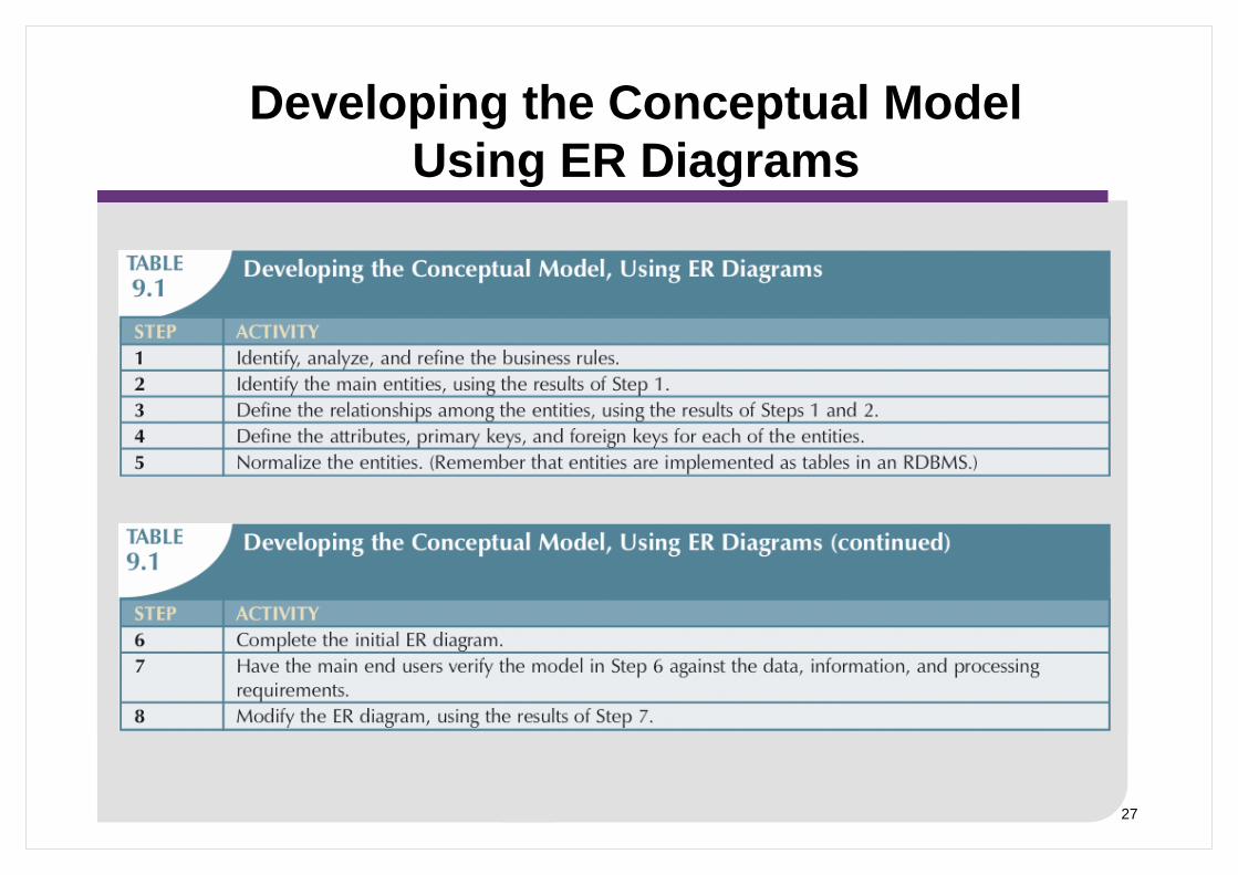
27
Developing the Conceptual Model Using ER Diagrams

28
Stage C: Data Model Verification
• Model must be verified against proposed system processes to corroborate that intended processes can be supported by database model
• Revision of original design starts with a careful reevaluation of entities, followed by a detailed examination of attributes that describe these entities
• Define design’s major components as modules:
– A module is an information system component that handles a specific function, eg. Orders, Inventory
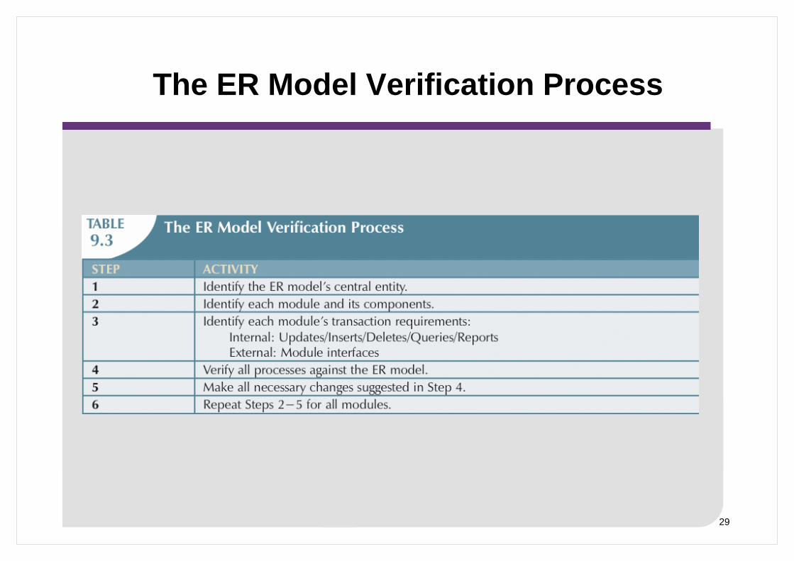
29
The ER Model Verification Process

30
Steps II and III
• Step II: DBMS Software Selection
– Critical to the information system’s smooth operation
– Advantages and disadvantages should be carefully studied
• Step III: Logical Design
– Used to translate conceptual design into internal model for a selected database management system
– Logical design is software-dependent
– Requires that all objects in the model be mapped to specific constructs used by selected database software
> Creates a database schema

31
Step IV: Physical Design
• Process of selecting data storage and data access characteristics of the database
• Storage characteristics are a function of device types supportedby the hardware, type of data access methods supported by system, and DBMS
• Particularly important in the older hierarchical and network models
• Becomes more complex when data are distributed at different locations
• Although we will examine the issues involved with physical design during this unit, we will not be able to have significantpractical experience with characteristics such as storage structures, access methods etc

32
Phase 3 Implementation and Loading
• New database implementation requires the creation of special storage-related constructs to house the end-user tables

33
Starting Phase 4 Testing and Evaluation
• Once the data has been loaded into the database the DBA tests and fine tunes the database for performance, integrity, concurrent access and security constraints
• Occurs in parallel with applications programming
• Database tools used to prototype applications
• If implementation fails to meet some of the system’s evaluation criteria
– Fine-tune specific system and DBMS configuration parameters
– Modify the physical design
– Modify the logical design
– Upgrade or change the DBMS software and/or the hardware platform

34
Operation / Maintenance and Evolution
• Operation– Once the database has passed the evaluation stage, it is
considered operational– Beginning of the operational phase starts the process of system
evolution• Required periodic maintenance:
– Preventive maintenance (backup)– Corrective maintenance (recovery)– Adaptive maintenance (enhancing performance, adding entities,
attributes, etc)• Assignment of access permissions and their maintenance for
new and old users• Generation of database access statistics • Periodic security audits • Periodic system-usage summaries
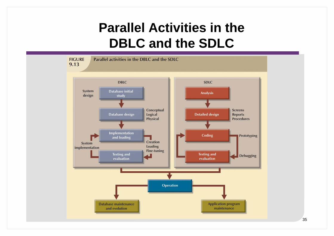
35
Parallel Activities in the DBLC and the SDLC

36
A Special Note about Database Design Strategies
• Two classical approaches to database design:– Top-down design
> Identifies data sets
> Defines data elements for each of those sets
> Involves the identification of different entity types and the definition of each entity’s attributes
– Bottom-up design > Identifies data elements (items)
> Groups them together in data sets
> First defines the attributes and then groups them to form entities
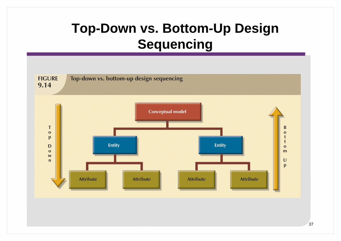
37
Top-Down vs. Bottom-Up Design Sequencing

38
Centralised vs. Decentralised Design
• Database design may be based on two very different design philosophies:
– Centralised design> Productive when the data component is composed of a relatively
small number of objects and procedures
> Typical of relatively simple small databases that can be successfully implemented by a single person (DBA) or a small design team
– Decentralised design> Used when the data component of system has considerable number
of entities and complex relations on which very complex operations are performed
> Likely to be used when the problem is spread across several operational sites and each element is a subset of the entire data set
> Involves a team of database designers

39
Centralised Design

40
Decentralised Design
41
Aggregation Process
• Requires designer to create a single model in which various aggregation problems must be addressed:
– Synonyms and homonyms
> Same object by different names (synonyms) or same name for different objects (homonyms)
– Entity and entity subtypes
> Integrate subtypes into a higher-level entity
– Conflicting object definitions
> Different datatypes, domains, constraints

42
Summary of Aggregation Problems

43
Summary
• This lecture– Describe the 3 level ANSI SPARC Database Architecture and the
advantages which its inherent data abstraction provide to the database developer
– Explain the role of database development within an information system
– Describe the steps involved in the Systems Development Life Cycle (SDLC)
– Explain the steps involved in the Database Life Cycle (DBLC) – Explain, in detail, within the Database Design phase of the DBLC, the
role of: ER modelling and Normalisation, Data Model Verification, Distributed Database Design, Logical and Physical Design
– Describe the database design strategies - Top-down vs. bottom-up design and Centralized vs. decentralized design
• Next lecture– The Relational Database Model