Embed Size (px)
Citation preview

Fisuel Internationnal Forum – Seoul / Korea – 04th & 05th of November, 2015
1

Fisuel Internationnal Forum – Seoul / Korea – 04th & 05th of November, 2015
2

Fisuel Internationnal Forum – Seoul / Korea – 04th & 05th of November, 2015
Risks Associated With Short Circuit Currents
•
•
Prepared by Hussein Salloum, OEA-FISUEL-Seoul October 2015 3

Fisuel Internationnal Forum – Seoul / Korea – 04th & 05th of November, 2015
Why Do I Need a Short Circuit Analysis?
•
•
Prepared by Hussein Salloum, OEA-FISUEL-Seoul October 2015 4

Fisuel Internationnal Forum – Seoul / Korea – 04th & 05th of November, 2015
Why Do I Need a Short Circuit Analysis?
•
•
Prepared by Hussein Salloum, OEA-FISUEL-Seoul October 2015 5

Fisuel Internationnal Forum – Seoul / Korea – 04th & 05th of November, 2015
Benefits of Running a Short Circuit Analysis
•
•
•
•
•
Prepared by Hussein Salloum, OEA-FISUEL-Seoul October 2015 6

Fisuel Internationnal Forum – Seoul / Korea – 04th & 05th of November, 2015
X-fmr Modeling
Prepared by Hussein Salloum, OEA-FISUEL-Seoul October 2015 7
Fisuel Internationnal Forum – Seoul / Korea – 04th & 05th of November, 2015
Prepared by Hussein Salloum, OEA-FISUEL-Seoul October 2015 8
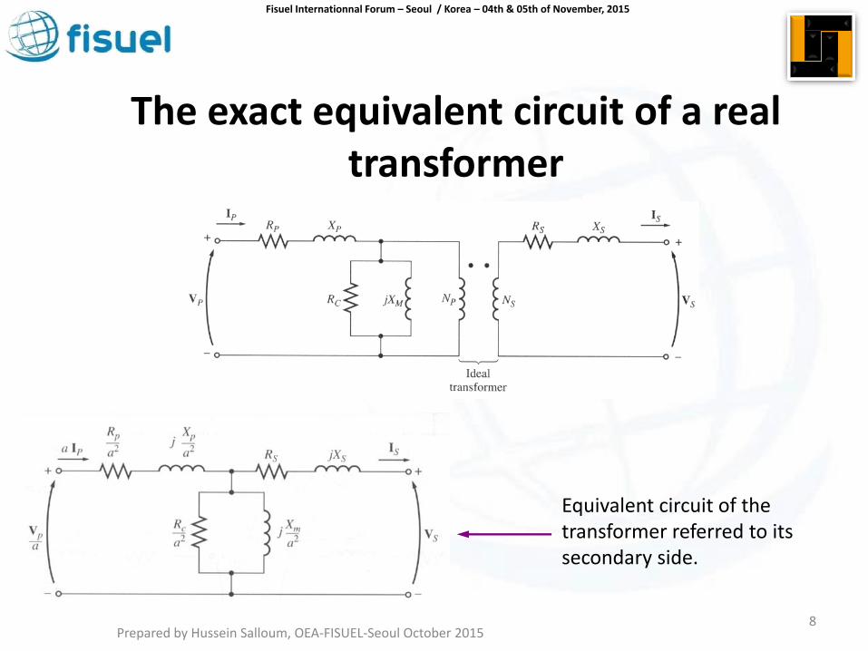
The exact equivalent circuit of a real transformer
Equivalent circuit of the transformer referred to its secondary side.

Fisuel Internationnal Forum – Seoul / Korea – 04th & 05th of November, 2015
Prepared by Hussein Salloum, OEA-FISUEL-Seoul October 2015 9
Approximate equivalent circuit of a transformer
Without an excitation branch referred to the secondary side.
The values of components of the transformer model can be determined experimentally by an open-circuit test or by a short-circuit test.

Fisuel Internationnal Forum – Seoul / Korea – 04th & 05th of November, 2015
Voltage Impedance
Prepared by Hussein Salloum, OEA-FISUEL-Seoul October 2015
10

Fisuel Internationnal Forum – Seoul / Korea – 04th & 05th of November, 2015
Medium Voltage Line
Sending end Receiving end
Primary Secondary
Zut Zx-fmr
Sending end Receiving end Short at the Secondary
U20 or U0
500MVA / 250MVA
If the short circuit power is infinite then Zut is zero
Psc Uo (V) Ra (mΩ) Xa (mΩ) 250 MVA 420 0.07 0.7
500 MVA 420 0.035 0.351
Admittance Method
Prepared by Hussein Salloum, OEA-FISUEL-Seoul October 2015
11

Fisuel Internationnal Forum – Seoul / Korea – 04th & 05th of November, 2015
Zeq = Zut + ZX-fmr
1/Aeq = 1/Aut + 1/ AX-fmr
V2/Seq= V2/Sut + V2/SX-fmr
1 / MVAsceq = 1 / MVAUt + 1 / MVAX-fmr
S = V2/Z or S = V2.A or
A = S/V2
Admittance Method
Prepared by Hussein Salloum, OEA-FISUEL-Seoul October 2015 12

Fisuel Internationnal Forum – Seoul / Korea – 04th & 05th of November, 2015
SYSTEM FAULT CURRENT
The MVA method is fast and simple as compared to the per unit or ohmic methods.
There is no need to convert to an MVA base or worry about voltage levels.
This is a useful method to obtain an estimated value of the fault current.
The elements have to be converted to an MVA value and then the circuit is converted to admittance values.
Prepared by Hussein Salloum, OEA-FISUEL-Seoul October 2015 13

Fisuel Internationnal Forum – Seoul / Korea – 04th & 05th of November, 2015
Prepared by Hussein Salloum, OEA-FISUEL-Seoul October 2015 14
The Impedance Method IEC 60909
Medium Voltage Line
Sending end
Receiving end
Primary Secondary
Za Zx-fmr
Sending end
Receiving end
Short at the Load
U20 or U0
Down stream load
Zload
ZT = Za + ZX-fmr + Zload
Down stream
X

Fisuel Internationnal Forum – Seoul / Korea – 04th & 05th of November, 2015
Psc Uo (V) Rut (mΩ) Xut (mΩ)
250 MVA 420 0.07 0.7
500 MVA 420 0.035 0.351
Network upstream of the MV/LV transformer
The 3-phase short-circuit fault level PSC, in kA or in MVA(1) is given by the power supply authority concerned, from which an equivalent impedance can be deduced.
(1) Short-circuit MVA: EL Isc where:
• EL = phase-to-phase nominal system voltage expressed in kV (r.m.s.) • Isc = 3-phase short-circuit current expressed in kA (r.m.s.)
(2) up to 36 kV
The table gives values for Ra and Xa corresponding to the most common MV(2) short-circuit levels in utility power-supply networks, namely, 250 MVA and 500 MVA.
Determination of the impedance of each component
Prepared by Hussein Salloum, OEA-FISUEL-Seoul October 2015 15

Fisuel Internationnal Forum – Seoul / Korea – 04th & 05th of November, 2015
Or Analytically where
Zs = Zut = impedance of the MV voltage network, expessed in milli-ohms
U20 = phase-to-phase no-load LV voltage, expressed in volts
Psc = MV 3-phase short-circuit fault level, expressed in kVA
The upstream (MV) resistance Ra is generally found to be negligible compared with
the corresponding Xa,
the latter then being taken as the ohmic value for Za.
If more accurate calculations are necessary, Xa may be taken to be equal to 0.995
Za and Ra equal to 0.1 Xa.
𝑍𝑠 =𝑈20
2
𝑃𝑠𝑐
Prepared by Hussein Salloum, OEA-FISUEL-Seoul October 2015 16

Fisuel Internationnal Forum – Seoul / Korea – 04th & 05th of November, 2015
Transformer: The impedance Ztr of a transformer,
as viewed from the LV terminals (secondary), is given by the formula: where:
U20 = open-circuit secondary phase-to-phase voltage expressed in volts
Sn = rating of the transformer (in kVA)
Usc = the short-circuit impedance voltage of the transformer expressed in %
The transformer windings resistance Rtr can be derived from the total losses as
follows (expressed in milli-ohms):
Pcu = total losses in watts
In = nominal full-load current in amps
Rtr = resistance of one phase of the transformer in milli-ohms (the LV and
corresponding MV winding for one LV phase are included in this resistance value).
• For an approximate calculation Rtr may be ignored since X ≈ Z in standard distribution type
transformers.
𝑍𝑡𝑟 =𝑈20
2
𝑆𝑛
×𝑈𝑠𝑐
100
𝑅𝑡𝑟 =𝑃𝑐𝑢 × 103
3 𝐼𝑛2
𝑋𝑡𝑟 = 𝑍𝑡𝑟2 − 𝑅𝑡𝑟
2
Prepared by Hussein Salloum, OEA-FISUEL-Seoul October 2015 17

Fisuel Internationnal Forum – Seoul / Korea – 04th & 05th of November, 2015
Circuit-breakers
In LV circuits, the impedance of circuit-breakers upstream of the fault location must
be taken into account. The reactance value conventionally assumed is 0.15 mΩ per
CB, while the resistance is neglected.
Busbars
The resistance of busbars is generally negligible, so that the impedance is
practically all reactive, and amounts to approximately 0.15 mΩ/metre(1) length for LV
busbars (doubling the spacing between the bars increases the reactance by about
10% only). (1) For 50 Hz systems, but 0.18 mΩ/m length at 60 Hz
Circuit conductors
The resistance of a conductor is given by the formula:
where
• ρ = the resistivity constant of the conductor material at the normal operating
temperature being:
• - 22.5 mΩ.mm2/m for copper
- 36 mΩ.mm2/m for aluminum
• L = length of the conductor in m
• S = c.s.a. of conductor in mm2 • Cable reactance values can be obtained from the manufacturers.
For c.s.a. of less than 50 mm2 reactance may be ignored.
In the absence of other information, a value of 0.08 mΩ/metre may be used (for 50 Hz systems) or 0.096
mΩ/metre (for 60 Hz systems).
For prefabricated bus-trunking and similar pre-wired ducting systems, the manufacturer should be
consulted.
𝑅𝑐 = 𝜌 𝐿
𝑆
Prepared by Hussein Salloum, OEA-FISUEL-Seoul October 2015 18

Fisuel Internationnal Forum – Seoul / Korea – 04th & 05th of November, 2015
Recapitulation table
Prepared by Hussein Salloum, OEA-FISUEL-Seoul October 2015 19
Fisuel Internationnal Forum – Seoul / Korea – 04th & 05th of November, 2015
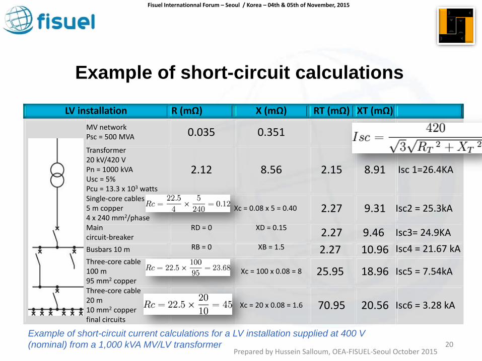
LV installation R (mΩ) X (mΩ) RT (mΩ) XT (mΩ)
MV network Psc = 500 MVA 0.035 0.351
Transformer 20 kV/420 V Pn = 1000 kVA Usc = 5% Pcu = 13.3 x 10³ watts
2.12 8.56 2.15 8.91 Isc 1=26.4KA
Single-core cables 5 m copper 4 x 240 mm2/phase
Xc = 0.08 x 5 = 0.40 2.27 9.31 Isc2 = 25.3kA
Main circuit-breaker
RD = 0 XD = 0.15 2.27 9.46 Isc3= 24.9KA
Busbars 10 m RB = 0 XB = 1.5 2.27 10.96 Isc4 = 21.67 kA Three-core cable 100 m 95 mm2 copper
Xc = 100 x 0.08 = 8 25.95 18.96 Isc5 = 7.54kA
Three-core cable 20 m 10 mm2 copper final circuits
Xc = 20 x 0.08 = 1.6 70.95 20.56 Isc6 = 3.28 kA
Example of short-circuit calculations
Example of short-circuit current calculations for a LV installation supplied at 400 V
(nominal) from a 1,000 kVA MV/LV transformer Prepared by Hussein Salloum, OEA-FISUEL-Seoul October 2015
20

Fisuel Internationnal Forum – Seoul / Korea – 04th & 05th of November, 2015
Prepared by Hussein Salloum, OEA-FISUEL-Seoul October 2015 21

Fisuel Internationnal Forum – Seoul / Korea – 04th & 05th of November, 2015
Prepared by Hussein Salloum, OEA-FISUEL-Seoul October 2015 22

Fisuel Internationnal Forum – Seoul / Korea – 04th & 05th of November, 2015
Prepared by Hussein Salloum, OEA-FISUEL-Seoul October 2015 23

Fisuel Internationnal Forum – Seoul / Korea – 04th & 05th of November, 2015
Conclusions
•
•
•
Prepared by Hussein Salloum, OEA-FISUEL-Seoul October 2015 24

Fisuel Internationnal Forum – Seoul / Korea – 04th & 05th of November, 2015
Theoretical or Standards method?
•
•
•
Prepared by Hussein Salloum, OEA-FISUEL-Seoul October 2015 25

Fisuel Internationnal Forum – Seoul / Korea – 04th & 05th of November, 2015
Theoretical Approach - Classical
Prepared by Hussein Salloum, OEA-FISUEL-Seoul October 2015 26

Fisuel Internationnal Forum – Seoul / Korea – 04th & 05th of November, 2015
The IEC Method is more practical
• The IEC calculation method is based on the same quantities as used to be calculated before.
• However, it differs from the classical method because it makes it possible to study circuits derived from the original one: one resistive only and one reactive only.
• This is the significant difference between standards methods and the classical calculation procedures.
• The IEC method proved to have offered a much more practical approach than the others.
Prepared by Hussein Salloum, OEA-FISUEL-Seoul October 2015 27

Fisuel Internationnal Forum – Seoul / Korea – 04th & 05th of November, 2015
THANK YOU
MERCI
감사합니다
Prepared by Hussein Salloum, OEA-FISUEL-Seoul October 2015 28

Fisuel Internationnal Forum – Seoul / Korea – 04th & 05th of November, 2015
793.5V
In 13.8KV
Ics
1000KVA
13.8KV - 480Y/277V.
Full Load Ampere
In = S / √3 x VL-L = 1000 KVA/√3 x 480V
In = FLA = 1,202Amps
When the secondary ampere meter reads 1,202A
the primary Voltage Meter reads 793.5V.
The percent of impedance value is
793.5 volts / 13800 volts = 0.0575.
Hence, % Z = 5.75%
And the Short Circuit becomes:
17.39 x the FLA = 20,903A
Practically
Prepared by Hussein Salloum, OEA-FISUEL-Seoul October 2015 29

Fisuel Internationnal Forum – Seoul / Korea – 04th & 05th of November, 2015
Therefore the main breaker
that is to be installed in the circuit on the secondary of the transformer
has to have a KA Interrupting Rating
greater than 21,000A.
Prepared by Hussein Salloum, OEA-FISUEL-Seoul October 2015 30

Fisuel Internationnal Forum – Seoul / Korea – 04th & 05th of November, 2015
Utility MVA at the Primary of the Transformer Case of MVAsc = 500MVA
√3 x VL-L Icc = 17.39 √3 x VL-L In
MVAsc of X-fmr Sn = 1MVA
Which Basically means that the short circuit at the primary of the X-fmr would withdraw a short circuit power of 500MVA.
Since X-fmr rating is at: 1000KVA = 1 MVA and Z = 5.75%
Therefore on its own would withdraw:
1MVA x 1/ .0575 = 17.39 MVA of short circuit power
Prepared by Hussein Salloum, OEA-FISUEL-Seoul October 2015 31

Fisuel Internationnal Forum – Seoul / Korea – 04th & 05th of November, 2015
Same Secondary Voltage
1 / MVAsceq = 1 / 500 + 1 / 17.39 = 0.002 + 0.06
MVAsceq = 1 / (0.002 + 0.06)= 16.13MVA which is less than 17.39MV (infinite impedance)
Therefore,
Short circuit current at 480V = MVAsceq / (1.73 x 0.48) =
16.129 / 0.8304 = 19, 423A = 19.4KA Case of 500MVA
Prepared by Hussein Salloum, OEA-FISUEL-Seoul October 2015 32

Fisuel Internationnal Forum – Seoul / Korea – 04th & 05th of November, 2015
All cases
Case of Utility Source at Primary Short Circuit Current
Infinite 20,904A
500MVA 19,432A
250MVA 18,790A
• When the cable and its length is added to the circuit the fault current will decrease to a smaller value. Cable MVA Value MVAsc = KV2 / Z cable.
• Use the cable X & R values to calculate the Z value then add to the Admittance calculation. Prepared by Hussein Salloum, OEA-FISUEL-Seoul October 2015
33

Fisuel Internationnal Forum – Seoul / Korea – 04th & 05th of November, 2015
Rated Power (kVA)
Oil-immersed Cast-resin Usc (%) Rtr (mΩ) Xtr (mΩ) Ztr (mΩ) Usc (%) Rtr (mΩ) Xtr (mΩ) Ztr (mΩ)
100 4 37.9 59.5 70.6 6 37.0 99.1 105.8
160 4 16.2 41.0 44.1 6 18.6 63.5 66.2
200 4 11.9 33.2 35.3 6 14.1 51.0 52.9
250 4 9.2 26.7 28.2 6 10.7 41.0 42.3
315 4 6.2 21.5 22.4 6 8.0 32.6 33.6
400 4 5.1 16.9 17.6 6 6.1 25.8 26.5
500 4 3.8 13.6 14.1 6 4.6 20.7 21.2
630 4 2.9 10.8 11.2 6 3.5 16.4 16.8
800 6 2.9 12.9 13.2 6 2.6 13.0 13.2
1,000 6 2.3 10.3 10.6 6 1.9 10.4 10.6
1,250 6 1.8 8.3 8.5 6 1.5 8.3 8.5
1,600 6 1.4 6.5 6.6 6 1.1 6.5 6.6
2,000 6 1.1 5.2 5.3 6 0.9 5.2 5.3
Resistance, reactance and impedance values for typical distribution 400 V transformers with MV windings ≤20 kV
The impedance of the MV network referred to the LV side of the MV/LV transformer
Prepared by Hussein Salloum, OEA-FISUEL-Seoul October 2015 34

Fisuel Internationnal Forum – Seoul / Korea – 04th & 05th of November, 2015
Prepared by Hussein Salloum, OEA-FISUEL-Seoul October 2015 35

Fisuel Internationnal Forum – Seoul / Korea – 04th & 05th of November, 2015
Prepared by Hussein Salloum, OEA-FISUEL-Seoul October 2015 36

Fisuel Internationnal Forum – Seoul / Korea – 04th & 05th of November, 2015
THE CONTROVERSY OF ICU AND ICS
Icu is the abbreviation for Rated Ultimate Short-circuit breaking
capacity.
It is the maximum short-circuit current that the circuit breaker
can break and then gets checked by the following sequence.
• O – t – CO
– O - refers to a breaking operation
– CO - refers to a making operation followed by a breaking operation t -
refers to the time separating two operations, equal to 3 minutes or the
length of time needed to reset the breaker, whichever is longer
This is the current for which the circuit breaker is incapable to
carry its rated current continuously after the tests
proposed conditions according to a specified tests sequence do
not include the capability of the.
Prepared by Hussein Salloum, OEA-FISUEL-Seoul October 2015 37