Embed Size (px)
Citation preview
www.Fisher.com
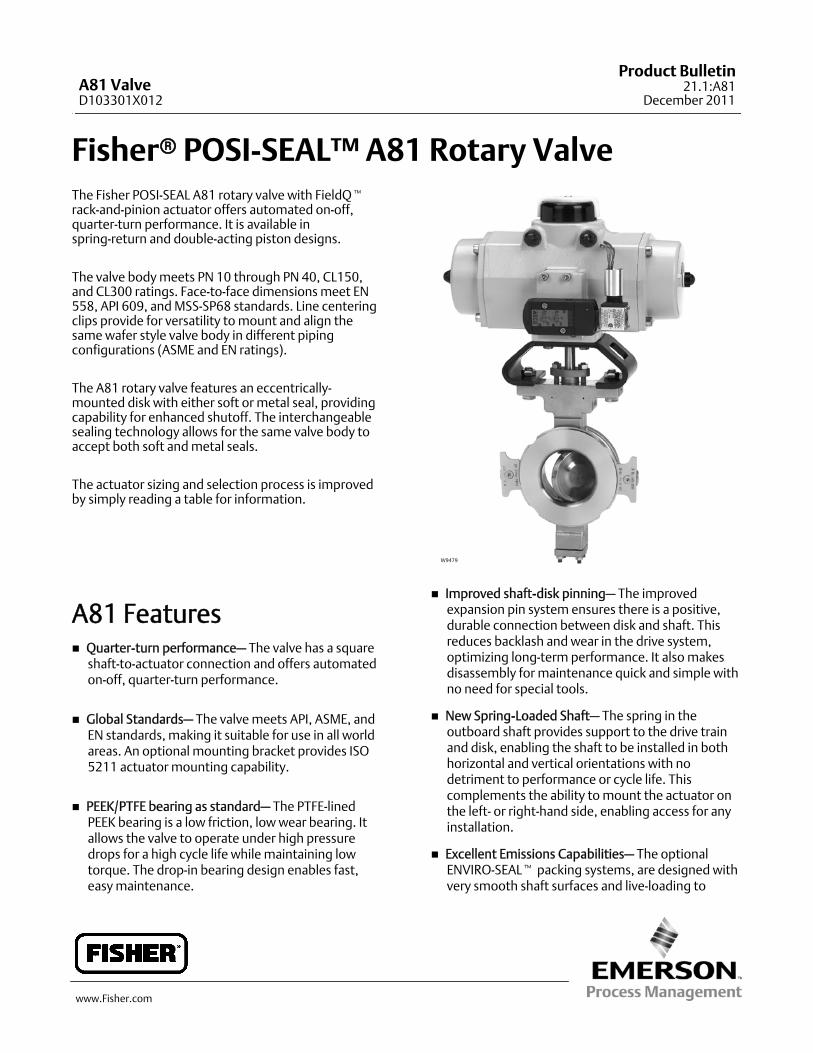
Fisherr POSI-SEAL™A81 Rotary ValveThe Fisher POSI-SEAL A81 rotary valve with FieldQtrack-and-pinion actuator offers automated on-off,quarter-turn performance. It is available inspring-return and double-acting piston designs.
The valve bodymeets PN 10 through PN 40, CL150,and CL300 ratings. Face-to-face dimensionsmeet EN558, API 609, andMSS-SP68 standards. Line centeringclips provide for versatility tomount and align thesamewafer style valve body in different pipingconfigurations (ASME and EN ratings).
The A81 rotary valve features an eccentrically-mounted disk with either soft or metal seal, providingcapability for enhanced shutoff. The interchangeablesealing technology allows for the same valve body toaccept both soft andmetal seals.
The actuator sizing and selection process is improvedby simply reading a table for information.
A81 Features Quarter-turn performance– The valve has a squareshaft-to-actuator connection and offers automatedon-off, quarter-turn performance.
Global Standards– The valvemeets API, ASME, andEN standards, making it suitable for use in all worldareas. An optional mounting bracket provides ISO5211 actuator mounting capability.
PEEK/PTFE bearing as standard– The PTFE-linedPEEK bearing is a low friction, lowwear bearing. Itallows the valve to operate under high pressuredrops for a high cycle life whilemaintaining lowtorque. The drop-in bearing design enables fast,easymaintenance.
W9479
Improved shaft-disk pinning– The improvedexpansion pin system ensures there is a positive,durable connection between disk and shaft. Thisreduces backlash and wear in the drive system,optimizing long-term performance. It alsomakesdisassembly for maintenance quick and simple withno need for special tools.
New Spring-Loaded Shaft– The spring in theoutboard shaft provides support to the drive trainand disk, enabling the shaft to be installed in bothhorizontal and vertical orientations with nodetriment to performance or cycle life. Thiscomplements the ability tomount the actuator onthe left- or right-hand side, enabling access for anyinstallation.
Excellent Emissions Capabilities– The optionalENVIRO-SEALt packing systems, are designed withvery smooth shaft surfaces and live-loading to
A81 ValveD103301X012
Product Bulletin21.1:A81
December 2011
A81 ValveD103301X012
Product Bulletin21.1:A81December 2011
2
provide improved sealing, guiding, and loadingforce transmission. The seal of the ENVIRO-SEALsystem can control emissions to below 100 ppm(parts per million).
Sour Service Capability– Depending onmaterialselection, some trim and boltingmaterials areavailable for applications involving sour liquids andgases. These constructions comply with NACEMR0175-2002, MR0103, andMR0175 / ISO 15156.Contact your Emerson Process Management salesoffice for more information.
Easy Installation– Line-centering clips engage theline flange bolts to simplify installation and providefor centering of wafer-style valves in the pipeline.End connections are compatible with EN and ASMEstandards.
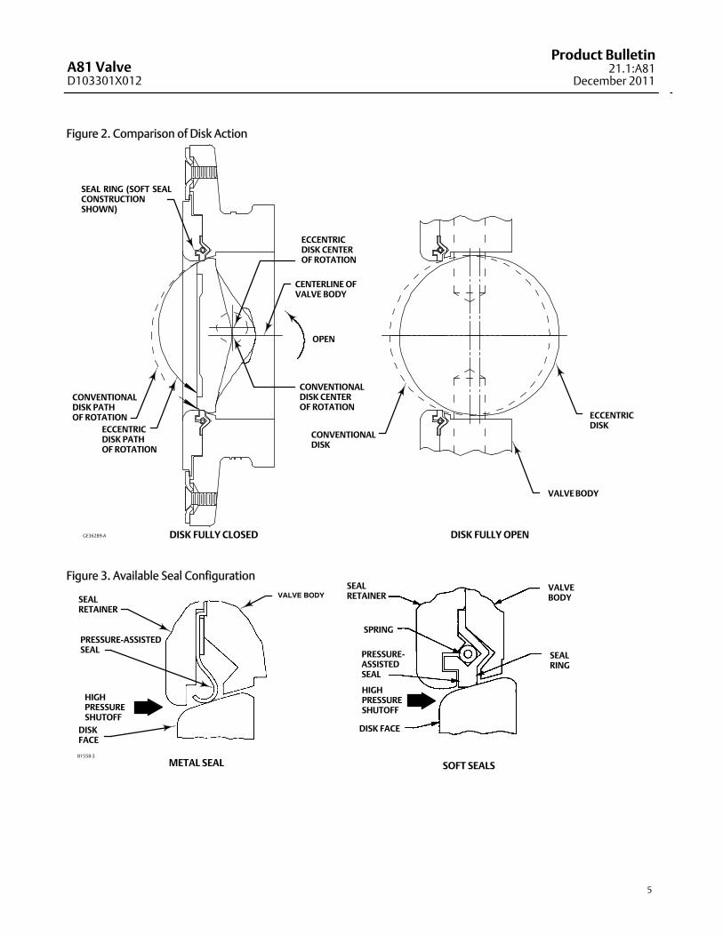
Excellent Shutoff Regardless of PressureDrop–Boththe S31600 (316 stainless steel) seal ring and thebidirectional PTFE seal ring with pressure-assistingsealing action ensure shutoff regardless of flowdirection.
Long Seal Life– The opening and closing path of theeccentric diskminimizes disk contact with the sealring, thereby reducing seal wear, undue friction,and seating torque requirements. Seefigure 2.
Reliable Flange Gasketing Surface– The sealretainer screws and retention clips are outside thegasket surface of the seal retainer. Spiral-wound orflat-sheet gaskets can be installed between theuninterrupted seal retainer face and the pipelineflange.
Integral Shaft-to-Valve Body Bonding– Standardvalve construction includes conductive packing toprovide electrical bonding for hazardous areaapplications.
Powder paint as standard– The Emerson ProcessManagementt powder paint finish offers anexcellent corrosion-resistant finish to all steel parts.
High Temperature Capability– The valve willoperate at elevated temperatures, with theappropriate trim components.
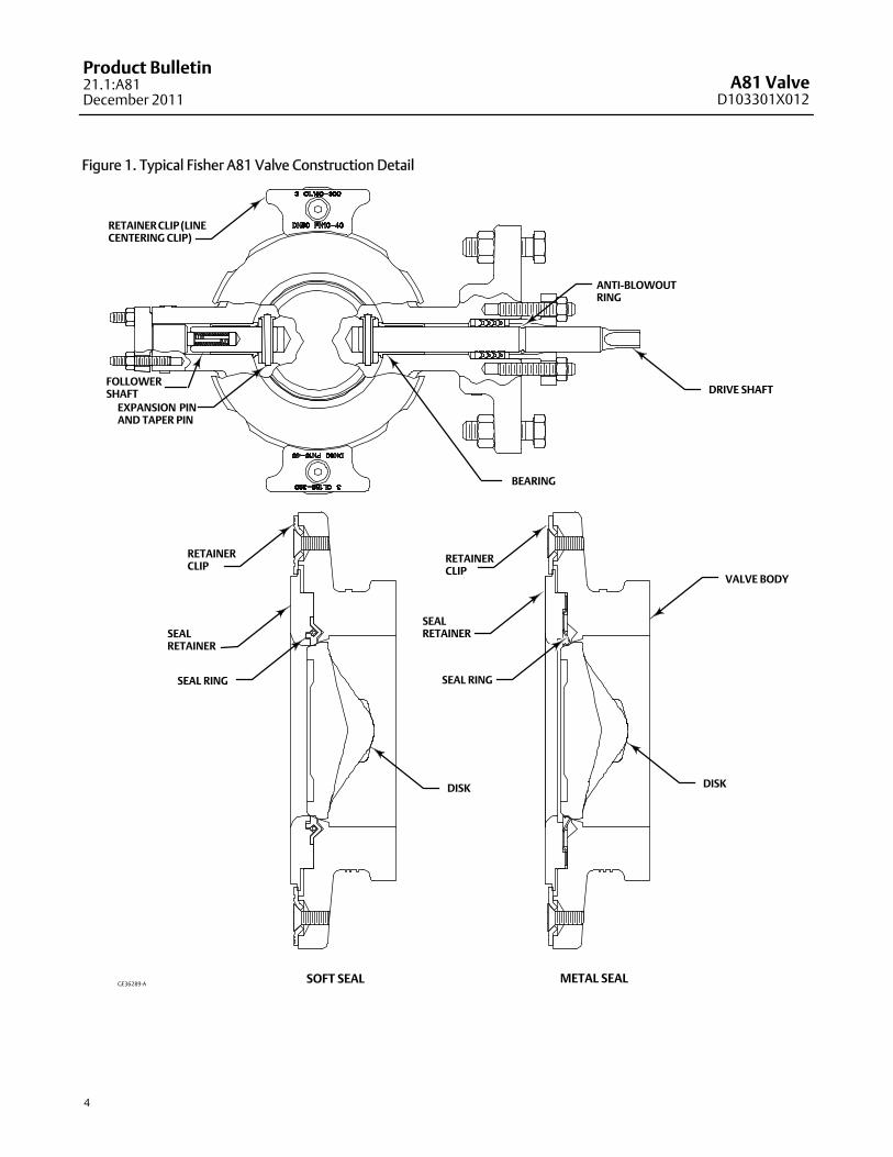
Shaft Retention– Redundant shaft retentionprovides added protection. The packing follower,anti-blowout ring, and shaft groove interact to holdthe shaft securely in the valve body (see figure 1).
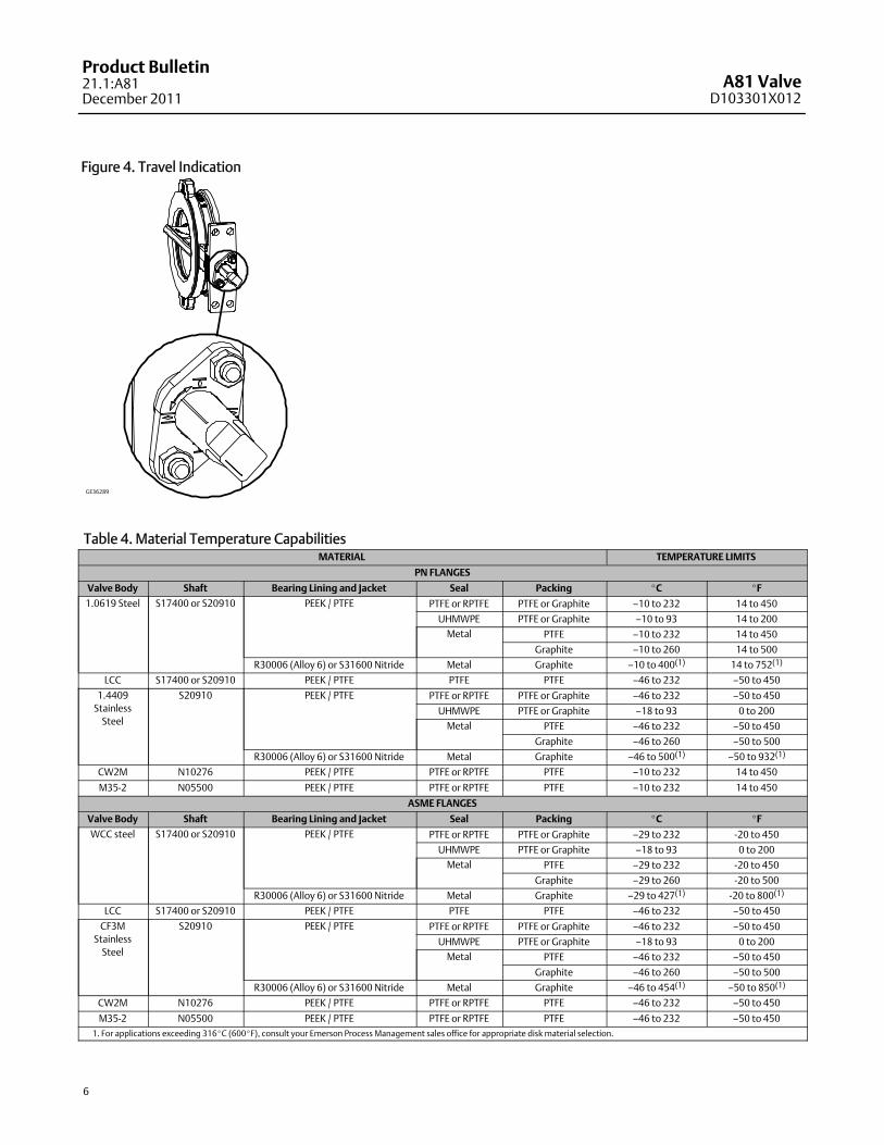
Travel Indication– Additional travel indication canbe achieved by using the indication line on theshaft, along with the disk positionmarkings on thepacking follower (see figure 4).
Table of ContentsA81 Features 1. . . . . . . . . . . . . . . . . . . . . . . . . . . . . . . .A81 Valve Specifications andMaterials of Construction 3. . . . . . . . . . . . . . . . . . .
Coefficients 15. . . . . . . . . . . . . . . . . . . . . . . . . . . . . . . .FieldQ Actuator Features 17. . . . . . . . . . . . . . . . . . . . .
A81 ValveD103301X012
Product Bulletin21.1:A81
December 2011
3
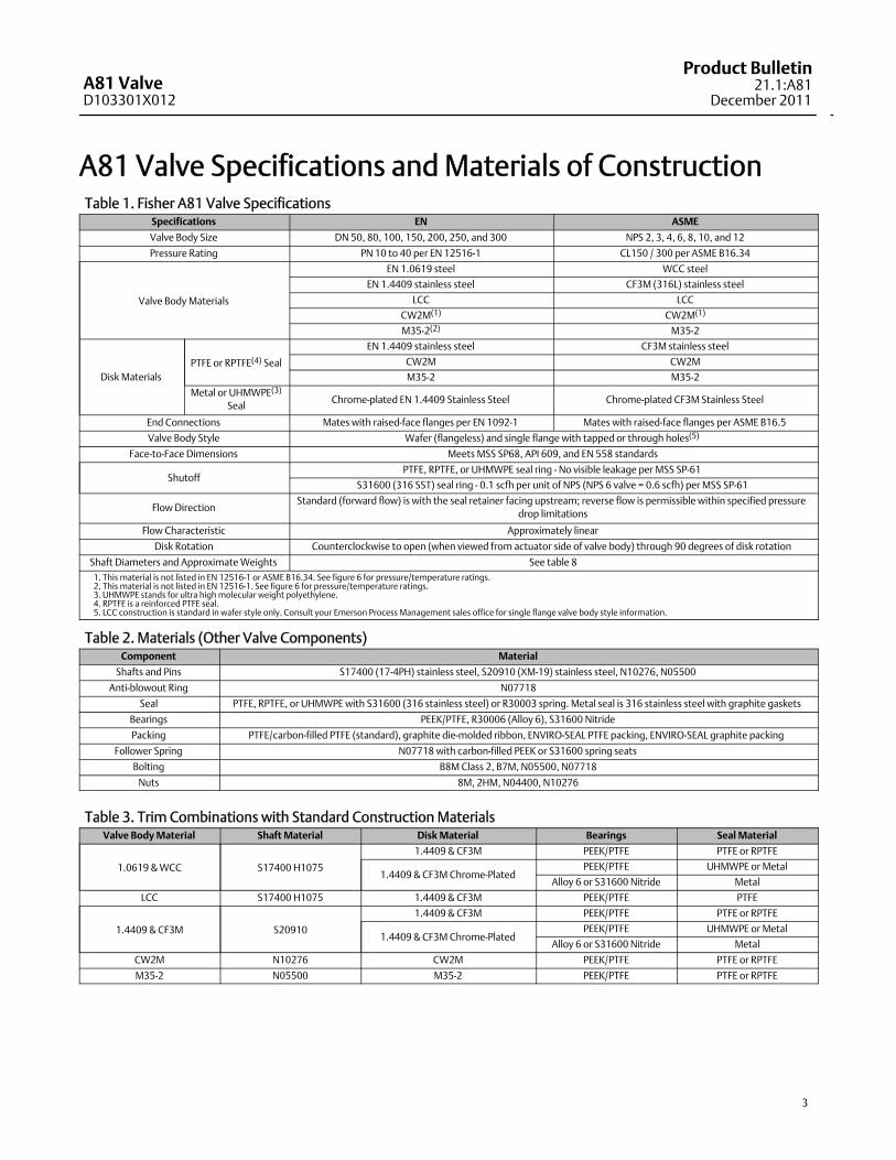
A81 Valve Specifications andMaterials of ConstructionTable 1. Fisher A81 Valve Specifications
Specifications EN ASME
Valve Body Size DN 50, 80, 100, 150, 200, 250, and 300 NPS 2, 3, 4, 6, 8, 10, and 12
Pressure Rating PN 10 to 40 per EN 12516-1 CL150 / 300 per ASME B16.34
Valve BodyMaterials
EN 1.0619 steel WCC steel
EN 1.4409 stainless steel CF3M (316L) stainless steel
LCC LCC
CW2M(1) CW2M(1)
M35-2(2) M35-2
Disk MaterialsPTFE or RPTFE(4) Seal
EN 1.4409 stainless steel CF3M stainless steel
CW2M CW2M
M35-2 M35-2
Metal or UHMWPE(3)
SealChrome-plated EN 1.4409 Stainless Steel Chrome-plated CF3M Stainless Steel
End Connections Mates with raised-face flanges per EN 1092-1 Mates with raised-face flanges per ASME B16.5
Valve Body Style Wafer (flangeless) and single flange with tapped or through holes(5)
Face-to-Face Dimensions Meets MSS SP68, API 609, and EN 558 standards
ShutoffPTFE, RPTFE, or UHMWPE seal ring -No visible leakage per MSS SP-61
S31600 (316 SST) seal ring - 0.1 scfh per unit of NPS (NPS 6 valve = 0.6 scfh) per MSS SP-61
FlowDirectionStandard (forward flow) is with the seal retainer facing upstream; reverse flow is permissible within specified pressure
drop limitations
Flow Characteristic Approximately linear
Disk Rotation Counterclockwise to open (when viewed from actuator side of valve body) through 90 degrees of disk rotation
Shaft Diameters and ApproximateWeights See table 81. This material is not listed in EN 12516-1 or ASME B16.34. See figure 6 for pressure/temperature ratings.2. This material is not listed in EN 12516-1. See figure 6 for pressure/temperature ratings.3. UHMWPE stands for ultra highmolecular weight polyethylene.4. RPTFE is a reinforced PTFE seal.5. LCC construction is standard in wafer style only. Consult your Emerson Process Management sales office for single flange valve body style information.
Table 2. Materials (Other Valve Components)Component Material
Shafts and Pins S17400 (17-4PH) stainless steel, S20910 (XM-19) stainless steel, N10276, N05500
Anti-blowout Ring N07718
Seal PTFE, RPTFE, or UHMWPEwith S31600 (316 stainless steel) or R30003 spring. Metal seal is 316 stainless steel with graphite gaskets
Bearings PEEK/PTFE, R30006 (Alloy 6), S31600 Nitride
Packing PTFE/carbon-filled PTFE (standard), graphite die-molded ribbon, ENVIRO-SEAL PTFE packing, ENVIRO-SEAL graphite packing
Follower Spring N07718 with carbon-filled PEEK or S31600 spring seats
Bolting B8MClass 2, B7M, N05500, N07718
Nuts 8M, 2HM, N04400, N10276
Table 3. Trim Combinations with Standard Construction MaterialsValve BodyMaterial ShaftMaterial DiskMaterial Bearings Seal Material
1.0619 &WCC S17400 H1075
1.4409 & CF3M PEEK/PTFE PTFE or RPTFE
1.4409 & CF3MChrome-PlatedPEEK/PTFE UHMWPE or Metal
Alloy 6 or S31600 Nitride Metal
LCC S17400 H1075 1.4409 & CF3M PEEK/PTFE PTFE
1.4409 & CF3M S20910
1.4409 & CF3M PEEK/PTFE PTFE or RPTFE
1.4409 & CF3MChrome-PlatedPEEK/PTFE UHMWPE or Metal
Alloy 6 or S31600 Nitride Metal
CW2M N10276 CW2M PEEK/PTFE PTFE or RPTFE
M35-2 N05500 M35-2 PEEK/PTFE PTFE or RPTFE
A81 ValveD103301X012
Product Bulletin21.1:A81December 2011
4
Figure 1. Typical Fisher A81 Valve Construction Detail
GE36289-A SOFT SEAL METAL SEAL
DISK
SEALRETAINER
RETAINERCLIP
VALVE BODY
SEAL RING
SEALRETAINER
RETAINERCLIP
DISK
DRIVE SHAFTFOLLOWERSHAFTEXPANSION PINAND TAPER PIN
BEARING
RETAINERCLIP(LINECENTERING CLIP)
ANTI-BLOWOUTRING
SEAL RING
A81 ValveD103301X012
Product Bulletin21.1:A81
December 2011
5
Figure 2. Comparison of Disk Action
DISK FULLY CLOSED DISK FULLY OPEN
VALVEBODY
ECCENTRICDISK
CONVENTIONALDISK
OPEN
ECCENTRICDISK CENTEROF ROTATION
CONVENTIONALDISK CENTEROF ROTATION
CENTERLINE OFVALVE BODY
SEAL RING (SOFT SEALCONSTRUCTIONSHOWN)
ECCENTRICDISK PATHOF ROTATION
CONVENTIONALDISK PATHOF ROTATION
GE36289-A
Figure 3. Available Seal Configuration
SOFT SEALS
SPRING
PRESSURE-ASSISTEDSEAL
HIGHPRESSURESHUTOFF
DISK FACE
VALVEBODY
SEALRING
PRESSURE-ASSISTEDSEAL
HIGHPRESSURESHUTOFFDISKFACE
VALVE BODY
B1558-3
METAL SEAL
SEALRETAINER
SEALRETAINER
A81 ValveD103301X012
Product Bulletin21.1:A81December 2011
6
Figure 4. Travel Indication
GE36289
Table 4. Material Temperature CapabilitiesMATERIAL TEMPERATURE LIMITS
PN FLANGES
Valve Body Shaft Bearing Lining and Jacket Seal Packing _C _F
1.0619 Steel S17400 or S20910 PEEK / PTFE PTFE or RPTFE PTFE or Graphite —10 to 232 14 to 450
UHMWPE PTFE or Graphite —10 to 93 14 to 200Metal PTFE —10 to 232 14 to 450
Graphite —10 to 260 14 to 500
R30006 (Alloy 6) or S31600 Nitride Metal Graphite —10 to 400(1) 14 to 752(1)
LCC S17400 or S20910 PEEK / PTFE PTFE PTFE —46 to 232 —50 to 450
1.4409StainlessSteel
S20910 PEEK / PTFE PTFE or RPTFE PTFE or Graphite —46 to 232 —50 to 450
UHMWPE PTFE or Graphite —18 to 93 0 to 200Metal PTFE —46 to 232 —50 to 450
Graphite —46 to 260 —50 to 500
R30006 (Alloy 6) or S31600 Nitride Metal Graphite —46 to 500(1) —50 to 932(1)
CW2M N10276 PEEK / PTFE PTFE or RPTFE PTFE —10 to 232 14 to 450
M35-2 N05500 PEEK / PTFE PTFE or RPTFE PTFE —10 to 232 14 to 450
ASME FLANGES
Valve Body Shaft Bearing Lining and Jacket Seal Packing _C _F
WCC steel S17400 or S20910 PEEK / PTFE PTFE or RPTFE PTFE or Graphite —29 to 232 -20 to 450
UHMWPE PTFE or Graphite —18 to 93 0 to 200Metal PTFE —29 to 232 -20 to 450
Graphite —29 to 260 -20 to 500
R30006 (Alloy 6) or S31600 Nitride Metal Graphite —29 to 427(1) -20 to 800(1)
LCC S17400 or S20910 PEEK / PTFE PTFE PTFE —46 to 232 —50 to 450
CF3MStainlessSteel
S20910 PEEK / PTFE PTFE or RPTFE PTFE or Graphite —46 to 232 —50 to 450
UHMWPE PTFE or Graphite —18 to 93 0 to 200Metal PTFE —46 to 232 —50 to 450
Graphite —46 to 260 —50 to 500
R30006 (Alloy 6) or S31600 Nitride Metal Graphite —46 to 454(1) —50 to 850(1)
CW2M N10276 PEEK / PTFE PTFE or RPTFE PTFE —46 to 232 —50 to 450
M35-2 N05500 PEEK / PTFE PTFE or RPTFE PTFE —46 to 232 —50 to 4501. For applications exceeding 316_C (600_F), consult your Emerson Process Management sales office for appropriate disk material selection.
A81 ValveD103301X012
Product Bulletin21.1:A81
December 2011
7
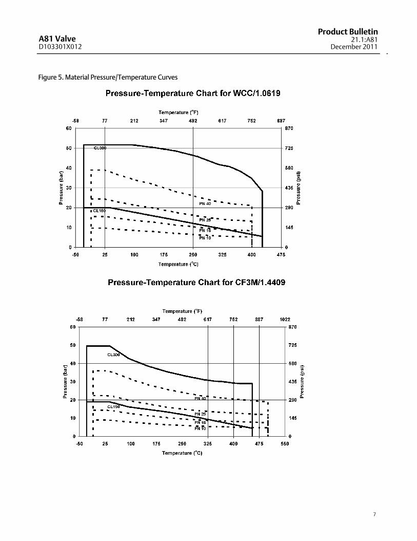
Figure 5. Material Pressure/Temperature Curves
A81 ValveD103301X012
Product Bulletin21.1:A81December 2011
8
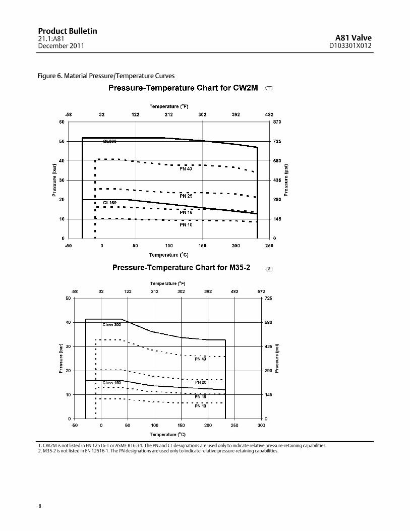
Figure 6. Material Pressure/Temperature Curves
1. CW2M is not listed in EN 12516-1 or ASME B16.34. The PN and CL designations are used only to indicate relative pressure-retaining capabilities.2. M35-2 is not listed in EN 12516-1. The PN designations are used only to indicate relative pressure-retaining capabilities.
1
2
A81 ValveD103301X012
Product Bulletin21.1:A81
December 2011
9
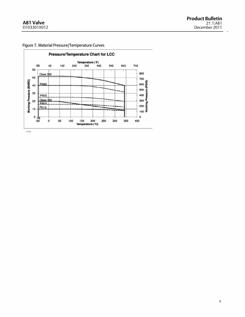
Figure 7. Material Pressure/Temperature Curves
E1140
A81 ValveD103301X012
Product Bulletin21.1:A81December 2011
10
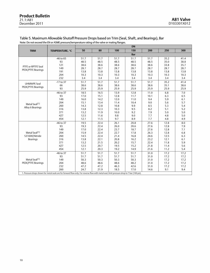
Table 5. MaximumAllowable Shutoff Pressure Drops based on Trim (Seal, Shaft, and Bearings), BarNote: Do not exceed the EN or ASME pressure/temperature rating of the valve ormating flanges.
TRIM TEMPERATURE, _C
DN
50 80 100 150 200 250 300
Bar
PTFE or RPTFE SealPEEK/PTFE Bearings
-46 to 6593121149191204232
51.748.538.628.713.810.33.4
51.748.538.628.713.810.33.4
51.748.538.628.713.810.33.4
51.748.538.628.713.810.33.4
51.748.538.628.713.810.33.4
35.235.033.828.713.810.33.4
41.438.835.728.713.810.33.4
UHMWPE SealPEEK/PTFE Bearings
-17 to 376693
51.738.625.9
51.738.625.9
51.738.625.9
51.738.625.9
51.738.625.9
35.235.125.9
41.438.625.9
Metal Seal(1)
Alloy 6 Bearings
-46 to 3793149204260316371427454
18.517.016.015.114.313.813.212.512.1
16.515.114.213.412.812.311.911.611.5
13.912.812.011.410.810.310.09.89.7
12.811.711.010.49.99.59.29.08.9
11.010.19.49.08.58.27.97.77.7
6.86.35.95.65.35.15.04.84.8
7.06.56.15.75.45.25.05.04.9
Metal Seal(1)
S31600/NitrideBearings
-46 to 3793149204260316371427454
19.519.317.015.914.513.813.212.512.1
22.422.422.422.422.422.121.520.720.3
26.126.023.722.721.420.820.219.519.2
20.820.618.717.816.816.215.715.214.9
27.627.627.626.324.623.222.421.821.6
12.812.812.812.812.512.111.811.411.2
8.07.97.16.86.36.15.95.65.4
Metal Seal(1)
PEEK/PTFE Bearings
-46 to 3793149204232260
51.751.750.348.647.224.7
51.751.750.348.647.221.9
51.751.750.348.646.318.5
51.751.750.348.242.617.0
31.031.031.031.031.014.6
17.217.217.217.217.29.1
17.217.217.217.217.29.4
1. Pressure drops shown for metal seals are for forward flow only. For reverse flow withmetal seal, limit pressure drop to 7 bar (100 psi).
A81 ValveD103301X012
Product Bulletin21.1:A81
December 2011
11
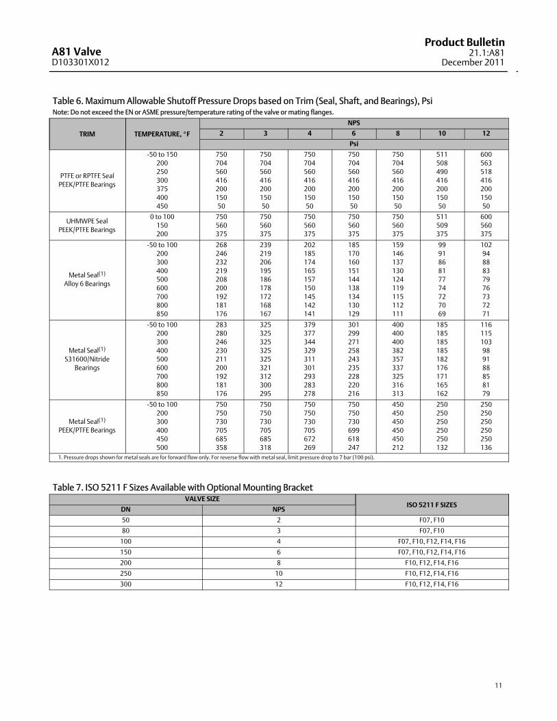
Table 6. MaximumAllowable Shutoff Pressure Drops based on Trim (Seal, Shaft, and Bearings), PsiNote: Do not exceed the EN or ASME pressure/temperature rating of the valve ormating flanges.
TRIM TEMPERATURE, _F
NPS
2 3 4 6 8 10 12
Psi
PTFE or RPTFE SealPEEK/PTFE Bearings
-50 to 150200250300375400450
75070456041620015050
75070456041620015050
75070456041620015050
75070456041620015050
75070456041620015050
51150849041620015050
60056351841620015050
UHMWPE SealPEEK/PTFE Bearings
0 to 100150200
750560375
750560375
750560375
750560375
750560375
511509375
600560375
Metal Seal(1)
Alloy 6 Bearings
-50 to 100200300400500600700800850
268246232219208200192181176
239219206195186178172168167
202185174165157150145142141
185170160151144138134130129
159146137130124119115112111
999186817774727069
1029488837976737271
Metal Seal(1)
S31600/NitrideBearings
-50 to 100200300400500600700800850
283280246230211200192181176
325325325325325321312300295
379377344329311301293283278
301299271258243235228220216
400400400382357337325316313
185185185185182176171165162
116115103989188858179
Metal Seal(1)
PEEK/PTFE Bearings
-50 to 100200300400450500
750750730705685358
750750730705685318
750750730705672269
750750730699618247
450450450450450212
250250250250250132
250250250250250136
1. Pressure drops shown for metal seals are for forward flow only. For reverse flow withmetal seal, limit pressure drop to 7 bar (100 psi).
Table 7. ISO 5211 F Sizes Available with Optional Mounting BracketVALVE SIZE
ISO 5211 F SIZESDN NPS
50 2 F07, F10
80 3 F07, F10
100 4 F07, F10, F12, F14, F16
150 6 F07, F10, F12, F14, F16
200 8 F10, F12, F14, F16
250 10 F10, F12, F14, F16
300 12 F10, F12, F14, F16
A81 ValveD103301X012
Product Bulletin21.1:A81December 2011
12
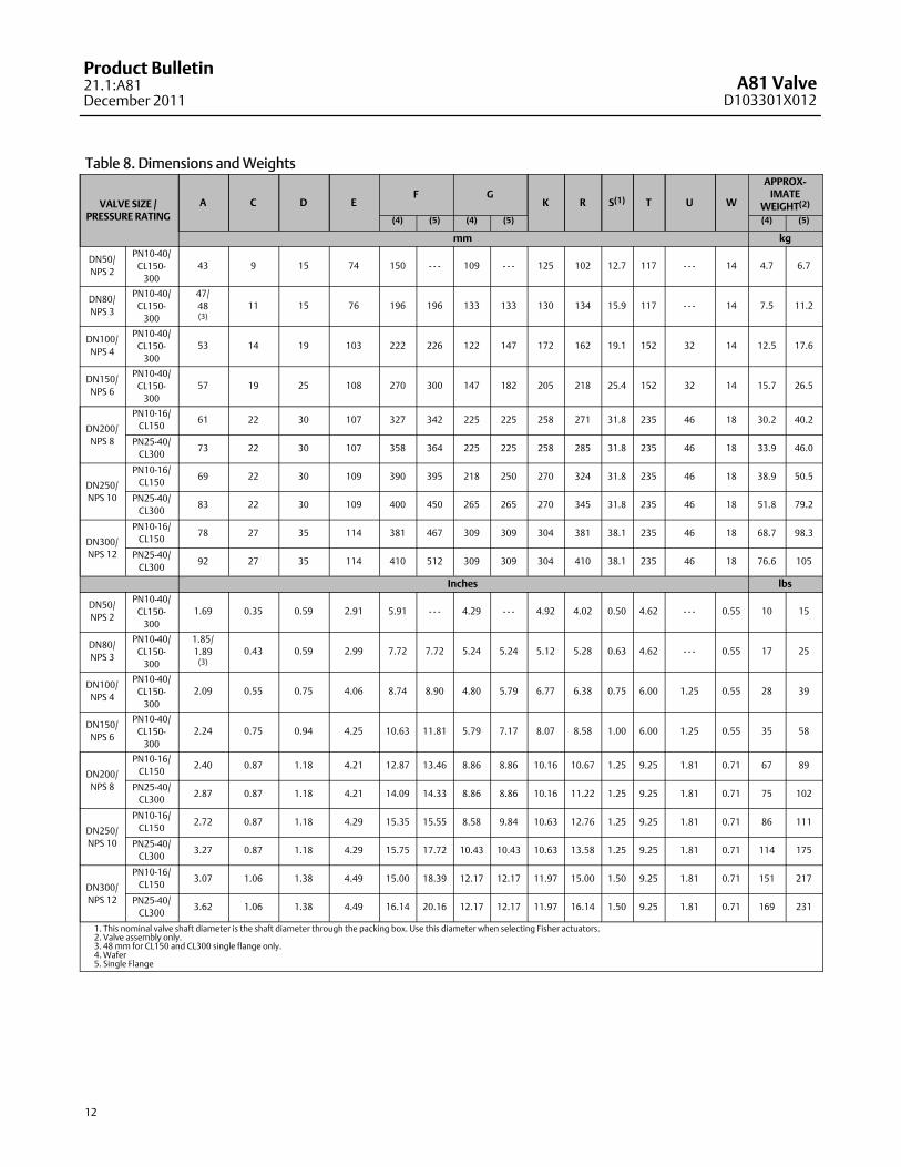
Table 8. Dimensions andWeights
VALVE SIZE /PRESSURE RATING
A C D EF G
K R S(1) T U W
APPROX-IMATE
WEIGHT(2)
(4) (5) (4) (5) (4) (5)
mm kg
DN50/NPS 2
PN10-40/CL150-300
43 9 15 74 150 - - - 109 - - - 125 102 12.7 117 - - - 14 4.7 6.7
DN80/NPS 3
PN10-40/CL150-300
47/48(3)
11 15 76 196 196 133 133 130 134 15.9 117 - - - 14 7.5 11.2
DN100/NPS 4
PN10-40/CL150-300
53 14 19 103 222 226 122 147 172 162 19.1 152 32 14 12.5 17.6
DN150/NPS 6
PN10-40/CL150-300
57 19 25 108 270 300 147 182 205 218 25.4 152 32 14 15.7 26.5
DN200/NPS 8
PN10-16/CL150
61 22 30 107 327 342 225 225 258 271 31.8 235 46 18 30.2 40.2
PN25-40/CL300
73 22 30 107 358 364 225 225 258 285 31.8 235 46 18 33.9 46.0
DN250/NPS 10
PN10-16/CL150
69 22 30 109 390 395 218 250 270 324 31.8 235 46 18 38.9 50.5
PN25-40/CL300
83 22 30 109 400 450 265 265 270 345 31.8 235 46 18 51.8 79.2
DN300/NPS 12
PN10-16/CL150
78 27 35 114 381 467 309 309 304 381 38.1 235 46 18 68.7 98.3
PN25-40/CL300
92 27 35 114 410 512 309 309 304 410 38.1 235 46 18 76.6 105
Inches lbs
DN50/NPS 2
PN10-40/CL150-300
1.69 0.35 0.59 2.91 5.91 - - - 4.29 - - - 4.92 4.02 0.50 4.62 - - - 0.55 10 15
DN80/NPS 3
PN10-40/CL150-300
1.85/1.89(3)
0.43 0.59 2.99 7.72 7.72 5.24 5.24 5.12 5.28 0.63 4.62 - - - 0.55 17 25
DN100/NPS 4
PN10-40/CL150-300
2.09 0.55 0.75 4.06 8.74 8.90 4.80 5.79 6.77 6.38 0.75 6.00 1.25 0.55 28 39
DN150/NPS 6
PN10-40/CL150-300
2.24 0.75 0.94 4.25 10.63 11.81 5.79 7.17 8.07 8.58 1.00 6.00 1.25 0.55 35 58
DN200/NPS 8
PN10-16/CL150
2.40 0.87 1.18 4.21 12.87 13.46 8.86 8.86 10.16 10.67 1.25 9.25 1.81 0.71 67 89
PN25-40/CL300
2.87 0.87 1.18 4.21 14.09 14.33 8.86 8.86 10.16 11.22 1.25 9.25 1.81 0.71 75 102
DN250/NPS 10
PN10-16/CL150
2.72 0.87 1.18 4.29 15.35 15.55 8.58 9.84 10.63 12.76 1.25 9.25 1.81 0.71 86 111
PN25-40/CL300
3.27 0.87 1.18 4.29 15.75 17.72 10.43 10.43 10.63 13.58 1.25 9.25 1.81 0.71 114 175
DN300/NPS 12
PN10-16/CL150
3.07 1.06 1.38 4.49 15.00 18.39 12.17 12.17 11.97 15.00 1.50 9.25 1.81 0.71 151 217
PN25-40/CL300
3.62 1.06 1.38 4.49 16.14 20.16 12.17 12.17 11.97 16.14 1.50 9.25 1.81 0.71 169 231
1. This nominal valve shaft diameter is the shaft diameter through the packing box. Use this diameter when selecting Fisher actuators.2. Valve assembly only.3. 48mm for CL150 and CL300 single flange only.4. Wafer5. Single Flange
A81 ValveD103301X012
Product Bulletin21.1:A81
December 2011
13
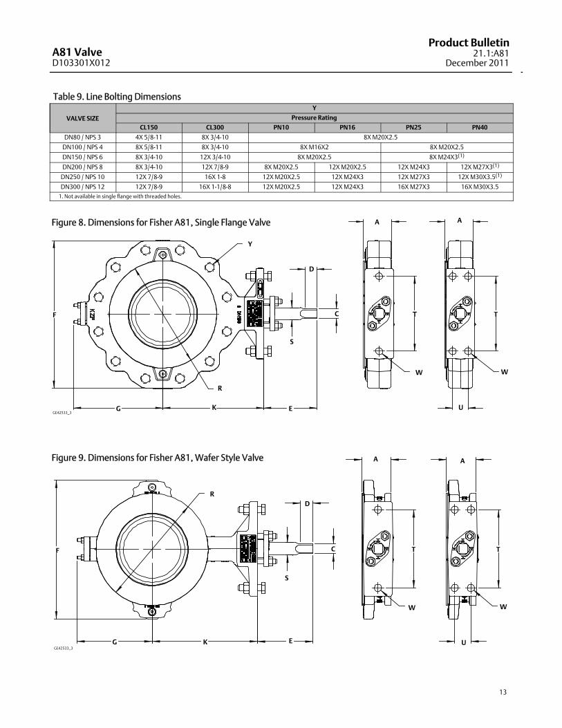
Table 9. Line Bolting Dimensions
VALVE SIZE
Y
Pressure Rating
CL150 CL300 PN10 PN16 PN25 PN40
DN80 / NPS 3 4X 5/8-11 8X 3/4-10 8XM20X2.5
DN100 / NPS 4 8X 5/8-11 8X 3/4-10 8XM16X2 8XM20X2.5
DN150 / NPS 6 8X 3/4-10 12X 3/4-10 8XM20X2.5 8XM24X3(1)
DN200 / NPS 8 8X 3/4-10 12X 7/8-9 8XM20X2.5 12XM20X2.5 12XM24X3 12XM27X3(1)
DN250 / NPS 10 12X 7/8-9 16X 1-8 12XM20X2.5 12XM24X3 12XM27X3 12XM30X3.5(1)
DN300 / NPS 12 12X 7/8-9 16X 1-1/8-8 12XM20X2.5 12XM24X3 16XM27X3 16XM30X3.51. Not available in single flange with threaded holes.
Figure 8. Dimensions for Fisher A81, Single Flange Valve AA
T T
W W
U
R
S
F
G K E
Y
C
D
GE42533_3
Figure 9. Dimensions for Fisher A81, Wafer Style Valve A A
U
W
T T
W
S
D
KG
R
F C
GE42533_3
E
A81 ValveD103301X012
Product Bulletin21.1:A81December 2011
14
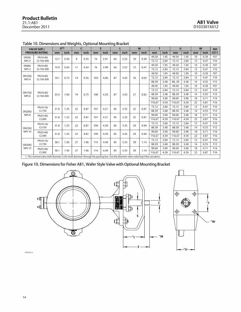
Table 10. Dimensions andWeights, Optional Mounting BracketVALVE SIZE /
PRESSURE RATINGS(1) C E L M T U W ISO
5211mm inch mm inch mm inch mm inch mm inch mm inch mm inch mm inch
DN50/NPS 2
PN10-40/CL150-300
12.7 0.50 9 0.35 74 2.91 64 2.52 10 0.3949.50 1.95 49.50 1.95 10 0.39 F07
72.12 2.84 72.12 2.84 12 0.47 F10
DN80/NPS 3
PN10-40/CL150-300
15.9 0.63 11 0.43 76 2.99 64 2.52 12 0.4749.50 1.95 49.50 1.95 10 0.39 F07
72.12 2.84 72.12 2.84 12 0.47 F10
DN100/NPS 4
PN10-40/CL150-300 19.1 0.75 14 0.55 103 4.06 87 3.43 16 0.63
49.50 1.95 49.50 1.95 10 0.39 F07
72.12 2.84 72.12 2.84 12 0.47 F10
88.39 3.48 88..39 3.48 14 0.55 F12
DN150/NPS 6
PN10-40/CL150-300 25.4 1.00 19 0.75 108 4.25 87 3.43 21 0.82
49.50 1.95 49.50 1.95 10 0.39 F07
72.12 2.84 72.12 2.84 12 0.47 F10
88.39 3.48 88.39 3.48 14 0.55 F12
99.00 3.90 99.00 3.90 18 0.71 F14
116.67 4.59 116.67 4.59 22 0.87 F16
DN200/NPS 8
PN10-16/CL150
31.8 1.25 22 0.87 107 4.21 85 3.35 22 0.8772.12 2.84 72.12 2.84 12 0.47 F10
88.39 3.48 88.39 3.48 14 0.55 F12
PN25-40/CL300
31.8 1.25 22 0.87 107 4.21 85 3.35 22 0.8799.00 3.90 99.00 3.90 18 0.71 F14
116.67 4.59 116.67 4.59 22 0.87 F16
DN250/NPS 10
PN10-16/CL150
31.8 1.25 22 0.87 109 4.29 85 3.35 24 0.9472.12 2.84 72.12 2.84 12 0.47 F10
88.39 3.48 88.39 3.48 14 0.55 F12
PN25-40/CL300
31.8 1.25 22 0.87 109 4.29 85 3.35 24 0.9499.00 3.90 99.00 3.90 18 0.71 F14
116.67 4.59 116.67 4.59 22 0.87 F16
DN300/NPS 12
PN10-16/CL150
38.1 1.50 27 1.06 114 4.49 85 3.35 29 1.1472.12 2.84 72.12 2.84 12 0.47 F10
88.39 3.48 88.39 3.48 14 0.55 F12
PN25-40/CL300
38.1 1.50 27 1.06 114 4.49 85 3.35 29 1.1499.00 3.90 99.00 3.90 18 0.71 F14
116.67 4.59 116.67 4.59 22 0.87 F16
1. This nominal valve shaft diameter is the shaft diameter through the packing box. Use this diameter when selecting Fisher actuators.
Figure 10. Dimensions for Fisher A81, Wafer Style Valve with Optional Mounting Bracket
*U
*W
*T
S
C
GE42533_3
E
S
*L *M
A81 ValveD103301X012
Product Bulletin21.1:A81
December 2011
15
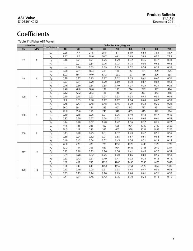
CoefficientsTable 11. Fisher A81 Valve
Valve SizeCoefficients
Valve Rotation, Degrees
DN NPS 10 20 30 40 50 60 70 80 90
50 2
Cv 2.28 7.7 21.5 35.5 51 58.9 62.4 78.3 83.7
Kv 1.97 6.7 18.6 30.7 44.1 50.9 53.9 67.7 72.3
Fd 0.16 0.21 0.21 0.25 0.29 0.32 0.36 0.37 0.39
FL - - - 0.91 0.84 0.76 0.73 0.78 0.80 0.68 0.66
XT - - - 0.76 0.53 0.39 0.39 0.52 0.54 0.39 0.35
80 3
Cv 3.50 22.1 46.3 73.1 120 147 181 239 275
Kv 3.02 19.1 40.0 63.2 103.7 127 156 206 238
Fd 0.10 0.17 0.23 0.27 0.32 0.33 0.41 0.47 0.51
FL 0.77 0.81 0.79 0.79 0.69 0.70 0.67 0.62 0.58
XT 0.46 0.60 0.54 0.55 0.40 0.37 0.35 0.29 0.23
100 4
Cv 9.40 48.8 90.6 137 171 224 297 397 484
Kv 8.12 42.2 78.3 118 148 194 257 343 418
Fd 0.10 0.18 0.23 0.28 0.33 0.38 0.43 0.50 0.53
FL 0.9 0.83 0.80 0.77 0.77 0.74 0.68 0.62 0.58
XT 0.48 0.47 0.48 0.48 0.46 0.39 0.32 0.26 0.22
150 6
Cv 26.2 99.1 181 283 401 543 717 951 1000
Kv 22.6 85.6 156 245 346 469 619 822 864
Fd 0.10 0.18 0.26 0.31 0.36 0.40 0.43 0.47 0.49
FL 0.82 0.79 0.77 0.74 0.72 0.68 0.66 0.61 0.58
XT 0.44 0.48 0.52 0.48 0.42 0.36 0.32 0.26 0.22
200 8
Cv 44.6 138 285 457 698 994 1390 2190 2550
Kv 38.5 119 246 395 603 859 1201 1892 2203
Fd 0.13 0.20 0.25 0.31 0.37 0.43 0.47 0.51 0.55
FL 0.86 0.94 0.82 0.71 0.68 0.67 0.61 0.54 0.47
XT 0.49 0.43 0.54 0.52 0.45 0.36 0.31 0.18 0.14
250 10
Cv 72.0 225 423 729 1150 1720 2440 3370 3720
Kv 62.2 194 365 630 994 1486 2108 2912 3214
Fd 0.12 0.18 0.23 0.26 0.36 0.41 0.45 0.57 0.54
FL 0.89 0.78 0.82 0.75 0.70 0.66 0.60 0.55 0.50
XT 0.53 0.42 0.57 0.49 0.41 0.32 0.23 0.18 0.16
300 12
Cv 128 401 733 1220 1800 2490 3380 4470 5080
Kv 111 346 633 1054 1555 2151 2920 3862 4389
Fd 0.13 0.19 0.25 0.31 0.38 0.44 0.47 0.50 0.53
FL 0.83 0.73 0.74 0.70 0.69 0.66 0.61 0.51 0.50
XT 0.41 0.34 0.46 0.42 0.36 0.30 0.24 0.18 0.16
A81 ValveD103301X012
Product Bulletin21.1:A81December 2011
16
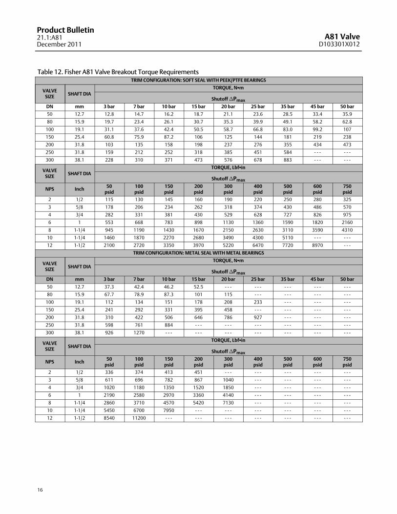
Table 12. Fisher A81 Valve Breakout Torque RequirementsTRIM CONFIGURATION: SOFT SEALWITH PEEK/PTFE BEARINGS
VALVESIZE SHAFT DIA
TORQUE, NSm
ShutoffnPmaxDN mm 3 bar 7 bar 10 bar 15 bar 20 bar 25 bar 35 bar 45 bar 50 bar
50 12.7 12.8 14.7 16.2 18.7 21.1 23.6 28.5 33.4 35.9
80 15.9 19.7 23.4 26.1 30.7 35.3 39.9 49.1 58.2 62.8
100 19.1 31.1 37.6 42.4 50.5 58.7 66.8 83.0 99.2 107
150 25.4 60.8 75.9 87.2 106 125 144 181 219 238
200 31.8 103 135 158 198 237 276 355 434 473
250 31.8 159 212 252 318 385 451 584 - - - - - -
300 38.1 228 310 371 473 576 678 883 - - - - - -
VALVESIZE SHAFT DIA
TORQUE, LbfSin
ShutoffnPmax
NPS Inch 50psid
100psid
150psid
200psid
300psid
400psid
500psid
600psid
750psid
2 1/2 115 130 145 160 190 220 250 280 325
3 5/8 178 206 234 262 318 374 430 486 570
4 3/4 282 331 381 430 529 628 727 826 975
6 1 553 668 783 898 1130 1360 1590 1820 2160
8 1-1/4 945 1190 1430 1670 2150 2630 3110 3590 4310
10 1-1/4 1460 1870 2270 2680 3490 4300 5110 - - - - - -
12 1-1/2 2100 2720 3350 3970 5220 6470 7720 8970 - - -
TRIM CONFIGURATION:METAL SEALWITHMETAL BEARINGS
VALVESIZE SHAFT DIA
TORQUE, NSm
ShutoffnPmaxDN mm 3 bar 7 bar 10 bar 15 bar 20 bar 25 bar 35 bar 45 bar 50 bar
50 12.7 37.3 42.4 46.2 52.5 - - - - - - - - - - - - - - -
80 15.9 67.7 78.9 87.3 101 115 - - - - - - - - - - - -
100 19.1 112 134 151 178 208 233 - - - - - - - - -
150 25.4 241 292 331 395 458 - - - - - - - - - - - -
200 31.8 310 422 506 646 786 927 - - - - - - - - -
250 31.8 598 761 884 - - - - - - - - - - - - - - - - - -
300 38.1 926 1270 - - - - - - - - - - - - - - - - - - - - -
VALVESIZE SHAFT DIA
TORQUE, LbfSin
ShutoffnPmax
NPS Inch 50psid
100psid
150psid
200psid
300psid
400psid
500psid
600psid
750psid
2 1/2 336 374 413 451 - - - - - - - - - - - - - - -
3 5/8 611 696 782 867 1040 - - - - - - - - - - - -
4 3/4 1020 1180 1350 1520 1850 - - - - - - - - - - - -
6 1 2190 2580 2970 3360 4140 - - - - - - - - - - - -
8 1-1/4 2860 3710 4570 5420 7130 - - - - - - - - - - - -
10 1-1/4 5450 6700 7950 - - - - - - - - - - - - - - - - - -
12 1-1/2 8540 11200 - - - - - - - - - - - - - - - - - - - - -
A81 ValveD103301X012
Product Bulletin21.1:A81
December 2011
17
FieldQ Actuator Features Simple, modular construction–Makes operationandmaintenance easier. The basic actuator moduleincludes the pistons, rack and pinion gear, springs(for spring-return actuators), housing, and positionindicator. Pneumatic operation is accomplishedwith an ASCO 8551 solenoid valve. The solenoid isactivated by a 120 VAC 60 Hz or 110 VAC 50 Hzsignal. It is padmounted and does not require abracket. The basic actuator features built-in visualposition indication, travel stops for both directions,and a balanced pinion design.
Three Point Suspension System–Three carbon-filledPTFE guide bands provide a low friction bearingsurface for piston alignment and rack support.Elimination ofmetal-to-metal contact betweenpistons and cylinder wall reduces friction foroutstanding cycle life, smooth piston travel, andmaximumpower.
Balanced Piston Design–As part of the design, threeequally spaced bearing surfaces are cast into each
piston. The rack and pinion construction results ineven distribution of bearing loads, optimumgearengagement, and reduced piston tilt. Equal springforce applied to each piston enhances actuator life.
Multiple Constructions–Conversion from doubleacting to spring return, or vice versa, is simple andsafe, thus reducing spare part requirements.Valve/actuator action is also field reversible.
Dual Stop Adjustment– This adjustment is standardon all E Series actuators. The P Series actuators aresupplied with a limit plate adjustment feature.
Dual Piston Design–Air pressure applies a balancedforce across the common pinion gear.Symmetrically balanced center mount constructioneliminates undue stress on the valve stem,bearings, and disk.
For further information, refer to:http://www.emersonprocess.com/valveautomation/fieldq/index.html

A81 ValveD103301X012
Product Bulletin21.1:A81December 2011
18

A81 ValveD103301X012
Product Bulletin21.1:A81
December 2011
19
A81 ValveD103301X012
Product Bulletin21.1:A81December 2011
20
Emerson Process ManagementMarshalltown, Iowa 50158 USASorocaba, 18087 BrazilChatham, Kent ME4 4QZ UKDubai, United Arab EmiratesSingapore 128461 Singapore
www.Fisher.com
The contents of this publication are presented for informational purposes only, and while every effort has beenmade to ensure their accuracy, they are notto be construed as warranties or guarantees, express or implied, regarding the products or services described herein or their use or applicability. All sales aregoverned by our terms and conditions, which are available upon request. We reserve the right tomodify or improve the designs or specifications of suchproducts at any timewithout notice.
EFisher Controls International LLC 2008, 2011; All Rights Reserved
Fisher, POSI-SEAL, FieldQ, and ENVIRO-SEAL aremarks owned by one of the companies in the Emerson Process Management business division of EmersonElectric Co. Emerson Process Management, Emerson, and the Emerson logo are trademarks and servicemarks of Emerson Electric Co. All other marks arethe property of their respective owners.
Neither Emerson, Emerson Process Management, nor any of their affiliated entities assumes responsibility for the selection, use or maintenanceof any product. Responsibility for proper selection, use, andmaintenance of any product remains solely with the purchaser and end user.


![?41 =A81 ;: B5;81:/1 -3-5:>? C;91: -:0 ?415= /4580=1:]](https://img.pdfslide.us/doc/110x75/618da9287aa52e4df34c2a95/41-a81-b5811-3-5gt-c91-0-415-45801.jpg)


![Stevie Database Completed Report December2011[1]](https://img.pdfslide.us/doc/110x75/577d22561a28ab4e1e971c74/stevie-database-completed-report-december20111.jpg)