Embed Size (px)
Citation preview

241
12Oryx and Escravos Gas-to-Liquids Facilities
12.1Introduction
The Oryx and Escravos gas-to-liquids (GTL) facilities were partly modeled on the Shell MiddleDistillate Synthesis (SMDS) process (Chapter 11) and design philosophy. These facilities donot produce final products, and the associated refinery is even simpler. The original intent wasto produce mainly distillates but without the coproduction of chemicals, although subsequentprojects were envisioned to expand production in the direction of lubricating base oils [1, 2].
The technologies that make up the GTL design come from three different companies and arethe same for both Oryx GTL and Escravos GTL processes [3, 4]:
1) Natural gas reforming, licensed by Haldor Topsøe.2) Fischer–Tropsch synthesis, licensed by Sasol Technology.3) Syncrude refining, licensed by ChevronTexaco.
The Oryx GTL venture started in July 1997, when a memorandum of understanding was signedbetween Qatar Petroleum, Sasol, and Philips Petroleum. The agreement called for the construc-tion of a 20 000 bbl/day Fischer–Tropsch-based GTL plant in Ras Laffan, Qatar. Philips Petroleumwithdrew from the project after the collapse of oil prices in 1998. By mid-2001, a new joint ventureagreement was reached, with Qatar Petroleum having a 51% stake and Sasol a 49% stake [5].
Natural gas from the Al Khaleej field was earmarked as feed. The natural gas supplyinfrastructure was already developed by a joint venture between Qatar Petroleum and ExxonMobil[6]. This allowed front-end engineering and design of a 34 000 bbl/day facility to proceed, whichwas called Oryx GTL. The product slate that was anticipated is given in Table 12.1 [7].
Oryx GTL achieved mechanical completion in 2006 and was officially opened in June 2006.The commissioning phase started in mid-2006 and the production of the first products wasannounced in February 2007 [8]. In mid-2007, it was reported that commissioning problemsin the Fischer–Tropsch synthesis section constrained output to 7000−10 000 bbl/day and thatadditional downstream equipment was required to overcome the problem [9]. By early 2008,production reached 20 000 bbl/day, and by August 2008 the average production was around24 000 bbl/day [10, 11].
The Escravos GTL facility initially was a joint venture between the Nigerian National PetroleumCompany, with a 25% stake, and Chevron Nigeria, with a 75% stake [12]. In a subsequent
Fischer–Tropsch Refining, First Edition. Arno de Klerk. 2011 Wiley-VCH Verlag GmbH & Co. KGaA. Published 2011 by Wiley-VCH Verlag GmbH & Co. KGaA.
242 12 Oryx and Escravos Gas-to-Liquids Facilities
Table 12.1 Design product slate for the 34 000 bbl/day OryxGTL facility.
Product Production (bbl/day)
Liquid petroleum gas 1 000Naphtha 7 000–9 000Distillate 24 000–26 000
agreement between Chevron and Sasol, the latter acquired a 37.5% stake but subsequentlyreduced it to 10% after the problems with Oryx GTL and the escalating cost of the project [11].
The engineering, procurement, and construction contract was awarded in April 2005, andfrom the outset the project faced problems with timing and the location. The facility has a designcapacity of 34 000 bbl/day and it is a clone of Oryx GTL. Civil unrest and necessary front-endengineering design changes were cited as the main causes for the delay in targeted completionfrom 2009 to 2011 [11].
Since Oryx GTL and Escravos GTL are similar in basic design, the subsequent discussionfocuses only on the former.
12.2Synthesis Gas Production in Oryx GTL
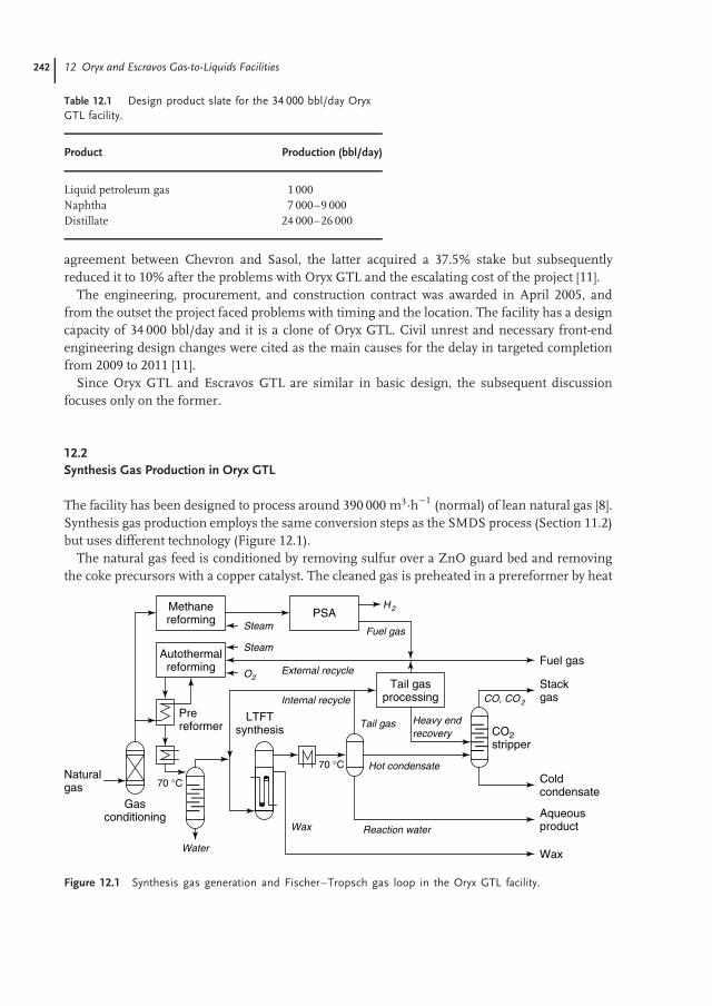
The facility has been designed to process around 390 000 m3·h−1 (normal) of lean natural gas [8].Synthesis gas production employs the same conversion steps as the SMDS process (Section 11.2)but uses different technology (Figure 12.1).
The natural gas feed is conditioned by removing sulfur over a ZnO guard bed and removingthe coke precursors with a copper catalyst. The cleaned gas is preheated in a prereformer by heat
Autothermalreforming
O2
Steam
Tail gasprocessing
Fuel gas
Wax Reaction water
Hot condensate
Gasconditioning
Methanereforming PSA
H2
Water
70 °C
70 °C
LTFTsynthesis Tail gas
Internal recycle
External recycle
Heavy endrecovery
CO, CO2
CO2stripper
Stackgas
Fuel gas
Naturalgas
Steam
Aqueousproduct
Coldcondensate
Wax
Prereformer
Figure 12.1 Synthesis gas generation and Fischer–Tropsch gas loop in the Oryx GTL facility.
12.3 Fischer–Tropsch Synthesis in Oryx GTL 243
exchange with the hot product gas from the autothermal reformer (ATR). In the prereformer, thenatural gas is reformed with steam to convert the C2 and heavier hydrocarbons in the natural gasto syngas (Section 3.4.2). This reduces the risk of carbon formation in the ATR. Prereforming isfollowed by adiabatic oxidative reforming in the ATR with pure O2 and steam. The O2 is suppliedfrom an air separation unit. The reformers and air separation units constituted 30% of the capitalcost of the project [13].
A separate steam reformer is used to convert some of the natural gas into a hydrogen-richsynthesis gas. The hydrogen is recovered in a pressure swing absorption (PSA) unit for use inthe refinery, while the hydrogen lean product is sent to the fuel gas system. The steam reformerproduces a more H2-rich syngas than the ATR and is used to adjust the H2:CO ratio of thesynthesis gas.
The syngas is cooled to about 70 ◦C to knock out the water and water-soluble gases in awater-wash column before it is used as feed for Fischer–Tropsch synthesis.
12.3Fischer–Tropsch Synthesis in Oryx GTL
The Fischer–Tropsch synthesis section makes use of the Sasol slurry-phase distillate (SPD)process, which is a new technology adapted from the Fe-LTFT slurry bed process that was com-mercialized in the Sasol 1 facility (Section 8.5.2). The same basic reactor technology is employed,but the SPD process uses a newly developed a cobalt-based low-temperature Fischer–Tropsch(Co-LTFT) catalyst [5]. Typical operating conditions are around 230 ◦C and 2.5 MPa.
The Co/Pt/Al2O3 LTFT catalyst is manufactured in a new catalyst preparation plant at DeMeern, The Netherlands. The catalyst manufacturing facility is operated by a Sasol–Engelhard(now BASF) joint venture. The Co/Pt/Al2O3 catalyst is claimed to be more resistant to reoxidationby water, allowing it to be more productive under high per pass conversion operation [14]. Catalyststability was evaluated under industrially relevant conditions during reaction in a 100 bbl/dayslurry bed unit. The unit was operated with a H2:CO ratio of 2 : 1 at 230 ◦C, 2 MPa, and a H2 + COconversion of 50–70%. Activity of the Co/Pt/Al2O3 catalyst was halved after 50 days on stream [15].
Oryx GTL uses two slurry bed reactors, each weighing 2100 tons. The reactors are about 60 m inheight and almost 10 m in diameter [13, 16]. The reactors were prefabricated and shipped becauseof the difficulty of on-site assembly [5]. Installation also required specialized lifting equipment.Construction and installation of this type of Fischer–Tropsch technology can consequently easilybecome critical path items during project execution. The Fischer–Tropsch synthesis sectionrepresents about 15% of the total capital cost of the facility [13].
The selection of a slurry bed reactor in combination with a Co-LTFT catalyst is somewhatsurprising. One of the main advantages of a slurry bed reactor over a fixed bed reactor is theability to add and remove catalyst while the reaction is in operation. Yet, one of the advantages ofCo-LTFT synthesis is its long catalyst lifetime. On-line catalyst addition and removal is thereforenot necessary. Although a slurry bed reactor has good heat transfer properties, it requiresliquid–solid separation and a catalyst with good attrition resistance.
The problems that were encountered during start-up of the Oryx GTL Fischer–Tropsch sectionwas related to attrition of the Co-LTFT catalyst. A fine sediment was formed due to catalystattrition. This caused clogging of downstream equipment and reduced throughput to a fraction

244 12 Oryx and Escravos Gas-to-Liquids Facilities
of the design capacity [9, 10]. These problems also resulted in an increased metal content inthe syncrude, which gave rise to a spate of patenting activity in the field of metal removal fromFischer–Tropsch wax to enable refining [17]. The deactivation mechanisms have been describedearlier (Sections 4.5.3 and 4.5.4).
The syncrude composition from Co-LTFT synthesis varies with the age of the catalyst, and atypical composition can be found in Table 1.2. The product from LTFT synthesis is filtered in thereactor to separate the catalyst from the hydrocarbon product. The catalyst remains in the reactorand the hot wax goes through a secondary filtration step before being sent to the refinery. It isat this point in the process where new technology had to be developed to reduce the metals thatremained in the wax.
The wax-free gaseous products are cooled down to about 70 ◦C to condense hydrocarbons andwater (Figure 12.1). The hydrocarbon fraction (hot condensate) is liquid–liquid phase separatedfrom the aqueous product (reaction water). The aqueous product contains some dissolvedoxygenates, such as methanol. The gaseous product (tail gas) that is not used for an internalrecycle in the Fischer–Tropsch gas loop is chilled to condense the C3 and heavier hydrocarbonsas well as some water that remained in the tail gas. The liquid product from this separation iscalled the heavy end recovery stream. The heavy end recovery stream and the hot condensate arepassed through a CO2 stripper column, where the dissolved CO and CO2 are removed before theoil is sent to the refinery as a cold condensate.
Uncondensed tail gas contains mainly C1 –C2 hydrocarbons, H2, CO, and CO2. Part of thisproduct is recycled directly to the ATR as an external recycle, with the rest being purged for useas fuel gas.
Some possibilities for process intensification based on reactor hydrodynamics have been noted[18]. The estimated capacity increase is 25–30%. In order to realize these benefits in practice, thecooling capacity of the slurry bed reactor will also have to be increased, and methods to accomplishthis were suggested. Considering the complexity of the reactor construction, it is not clear whetherit will be possible to realize these benefits with the installed equipment at the Oryx GTL facility.
12.4Fischer–Tropsch Refining in Oryx GTL
12.4.1Oil Refining
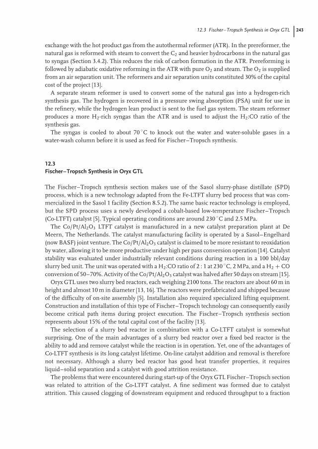
The refinery design of Oryx GTL is very simple and consists of a single conversion unit, ahydrocracker (Figure 12.2). It contributes only 10% to the overall capital cost of the facility[13]. It is only a partial refinery and it does not produce transportation fuels or chemicals, onlyintermediate products and LPG.
The refinery section receives two feed streams from the Fischer–Tropsch gas loop, namelywax and cold condensate. The wax and the cold condensate are combined to serve as feed tothe hydrocracker. The wax hydrocracker uses the ChevronTexaco Isocracking technology andcatalyst.
The hydrocracking catalyst is commercially available and it consists of sulfided base metalson an acidic support. Since the Fischer–Tropsch syncrude is sulfur-free, operation of this unit

12.4 Fischer–Tropsch Refining in Oryx GTL 245
Distillate
Naphtha
LPG
H2Hydrocracker Stabilizer
columnMain
fractionator
>360 °C
Wax
Coldcondensate
Bottom recycle
Hot HPseparator
Cold HPseparator
Sulfidingagent
Purge
Figure 12.2 Refinery section in the Oryx GTL facility.
requires that a sulfiding agent must be co-fed in order to keep the catalyst in a sulfided state.Typical operating conditions are a liquid hourly space velocity (LHSV) of 1.2 h−1, 350 ◦C, and7 MPa, with the temperature being adjusted to keep the per pass conversion at around 65%. Theproduct from hydrocracking is distilled to produce LPG (3–7%), naphtha (20–30%), and distillate(65–75%), with the unconverted >360 ◦C waxy product being recycled to the hydrocracker feed [7].
The straight-run naphtha has a research octane number of 50–55 and has a high content ofn-alkanes (Table 12.2) [7]. Since the naphtha fraction forms part of the cold condensate, the
Table 12.2 Characteristics of different naphtha fractions produced from Co-LTFT synthesis andrefining.
Property Straight run Hydrotreateda Hydrocracked
Density at 20 ◦C (kg·m–3) 710 683 688Cetane number – 42.7 30Cloud point (◦C)b –51 –54 –35Flash point (◦C) –9 –18 –21Distillation (◦C)
IBP (initial boiling point) 58 60 49T10 94 83 79T50 118 101 101T90 141 120 120FBP (final boiling point) 159 133 131
Composition (mass%)c
n-Alkanes 53.2 90.1 28.6Branched alkanes 1.2 8.3 66.7Alkenes 35 1.5 0Aromatics 0 0.1 0.5Oxygenates (alcohols) 10.7 0 0Sulfur <0.0001 <0.0001 <0.0001
aThe Oryx GTL refinery does not include a hydrotreater.bCloud point predicted from differential scanning calorimeter analysis.cSource reference values do not all add to 100%.

246 12 Oryx and Escravos Gas-to-Liquids Facilities
hydrocracker acts as hydrotreater, hydroisomerization unit, and hydrocracker for this fraction.Hydrocracking of the distillate and wax fractions further increases the volume of naphtha. Theproperties of the final product are very dependent on the operation of the hydrocracker and theproperties of the hydrocracking catalyst.
Since all of the naphtha passes through the hydrocracker, the product is paraffinic and then-alkane content is reduced by hydroisomerization. It was reported that the naphtha makes agood steam-cracking feedstock [19], and the intention was to market it as such.
The distillate has almost no sulfur, and the degree of branching is determined by thehydrocracker. The hydrocracked distillate has a high cetane number, but lacks the density tomeet EN590:2004 diesel fuel specifications (Table 12.3) [20–22]. The distillate can be fractionatedinto kerosene and gas oil, but this does not form part of the original Oryx GTL refinery design.The distillate that is produced is a diesel fuel blending stock.
Table 12.3 Properties of different hydrocracked distillaterange products from pilot plant operation and the industrialOryx GTL facility.
Property Sasol SPD pilot plant Oryx GTL
Kerosene Distillate Distillate
Density at 15 ◦C (kg·m−3) 747 769 771a
Cetane number – 72–73 87Viscosity at 40 ◦C (cSt) 4.2b 2.0 2.4Cold filter plugging point (◦C) – –19 –7Freezing point (◦C) –48 –15 –Smoke point (mm) >50 – –Flash point (◦C) 45 58 65Lubricity, HFRRc (µm) 500d 617 –Net heating value (MJ kg–1) 44.1 43.8 –Distillation (◦C)
IBP (initial boiling point) 154 151 168T10 168 182 206T50 191 249 268T90 254 325e 345FBP (final boiling point) 267 334 364
CompositionAlkenes (g Br/100 g) 0 0.6 –Aromatics (mass%) 0 0.1 <1Sulfur (mass%) <0.01 <0.0001 <0.0005Acidity (mg KOH/g) 0.009 0.001 –
aDensity at 20 ◦C.bViscosity at −20 ◦C.cHFRR, high-frequency reciprocating rig.dLubricity by ball-on-cylinder lubricity evaluator (BOCLE), ASTM D5001.eT95 distillation point.

12.5 Discussion of the Refinery Design 247
Table 12.4 Fischer–Tropsch aqueous product from Co-LTFT synthesis.
Compound Aqueous product (mass%)
Water 98.89Nonacid oxygenates 1Carboxylic acids 0.09Hydrocarbons 0.02Inorganic matter <0.005
12.4.2Aqueous Product Treatment
Approximately 1.3 tons of water is produced for every 1 ton of hydrocarbon. The Fischer–Tropschaqueous product is consequently a major product stream. It contains some dissolved oxygenates,which are mainly light alcohols (Table 12.4) [23].
The reaction water is separated by distillation into an alcohol-rich overhead product that isincinerated and a carboxylic acid–containing water-rich product that is biologically degraded topurify the water. No oxygenates are recovered from the reaction water. However, considering theseparation step that is already present in the facility, such recovery is readily achievable.
12.5Discussion of the Refinery Design
Superficially, the Oryx GTL refinery employed an analogous hydrocracker-based refinery designas the SMDS process but there are notable differences between the two refinery designs. Thesyncrude to the Oryx GTL refinery contains more alkenes and oxygenates than that to the SMDSrefinery. Although this provides the syncrude with more synthetic capability, it was not exploitedby the refinery design. In fact, the Oryx GTL refinery design did not exploit the properties of thesyncrude in any way, whereas the refinery technology selection and design of the SMDS refinerycapitalized on the properties of the syncrude. The capital cost contribution of the Oryx GTLrefinery is therefore less than that in the SMDS process, but the refining advantages provided bythe Co-LTFT syncrude were forfeited.
The concept of partial refining was taken to the extreme by the Oryx GTL design and itapproaches that of being just an upgrader.
1) Most of the alcohols in the aqueous product is recovered from the water effluent, but notrefined to final products.
2) With the refinery shown in Figure 12.2, it is not possible to produce higher value chem-ical products. The refinery lacks a separate hydrotreater and the supporting separationinfrastructure to produce chemicals such as waxes and paraffinic solvents.
3) The decision to produce only intermediate fuel-based products is surprising considering thetrend in all other industrial Fischer–Tropsch facilities to coproduce chemicals. Refining is

248 12 Oryx and Escravos Gas-to-Liquids Facilities
the step in any Fischer–Tropsch-based facility where most of the value addition takes placewith the least amount of capital. The Sasol 1 facility and the SMDS Bintulu facility are muchsmaller than Oryx GTL, but include more complex refineries, which supports the contentionthat there is economic merit in more extensive syncrude refining.
4) The hydrocracker design employs a sulfided base metal hydrocracking catalyst developed forcrude oil hydrocracking. This requires the addition of sulfur to an otherwise sulfur-free feed.It also requires hydrocracker operation under more severe conditions (>350 ◦C and 7 MPa)than is possible with a noble metal hydrocracking catalyst (300–350 ◦C and 3–5 MPa).A comparison between the two catalyst types clearly showed the benefit of noble metalhydrocracking in terms of product selectivity, especially at high per pass conversion [17].
References
1. Turner, C. (2005) Fundamentals of Gas to Liq-uids, 2nd edn, Petroleum Economist, London,pp. 5–7.
2. Dancuart, L.P. and Steynberg, A.P. (2007)Fischer-Tropsch based GTL technology: a newprocess? Stud. Surf. Sci. Catal., 163, 379–399.
3. Cook, P. (2003) Fundamentals of Gas to Liquids,1st edn, Petroleum Economist, London, p. 46.
4. Jay, M. (2003) Fundamentals of Gas to Liquids,1st edn, Petroleum Economist, London, p. 45.
5. Collings, J. (2002) Mind Over Matter. The SasolStory: A Half-century of Technological Innovation,Sasol, Johannesburg.
6. Daya, A. (2006) In vogue. Pet. Econ., 73 (4),27–28.
7. Dancuart, L.P., De Haan, R., and De Klerk, A.(2004) Processing of primary Fischer-Tropschproducts. Stud. Surf. Sci. Catal., 152, 482–532.
8. (2007) Oryx plant produces GTL products forfirst time. Oil Gas J. 105 (5), 10.
9. Forbes, A. (2007) Reality check. Pet. Econ., 74(7), 30.
10. (2008) GTL: Oryx breakthrough and oil-pricesurge lift industry spirits. Pet. Econ., 75 (6),36–38.
11. (2008) Sasol cuts stake in Escravos GTL as costsrise to $6bn. Pet. Econ., 75 (10), 30.
12. Fraser, K. (2005) Fundamentals of Gas to Liq-uids, 2nd edn, Petroleum Economist, London,pp. 15–16.
13. Halstead, K. (2008) Oryx GTL from conceptionto reality. Nitrogen+Syngas, 292, 43–50.
14. Espinoza, R.L., Steynberg, A.P., Jager, B.,and Vosloo, A.C. (1999) Low temperatureFischer-Tropsch synthesis from a Sasol per-spective. Appl. Catal. A, 186, 13–26.
15. Saib, A.M., Borgna, A., Van de Loosdrecht, J.,Van Berge, P.J., and Niemantsverdriet, J.W.(2006) XANES study of the susceptibility ofnano-sized cobalt crystallites to oxidation duringrealistic Fischer-Tropsch synthesis. Appl. Catal.A, 312, 12–19.
16. Forbes, A. (2007) Surge in interest a long timecoming. Pet. Econ., 74 (1), 19–20.
17. De Klerk, A. and Furimsky, E. (2010) Catalysisin the Refining of Fischer– Tropsch Syncrude,Royal Society of Chemistry, Cambridge.
18. Vogel, A., Steynberg, A.P., and Breman, B.(2007) Intensification of commercial slurryphase reactors. Stud. Surf. Sci. Catal., 167,61–66.
19. Dancuart, L.P., Mayer, J.F., Tallman, M.J., andAdams, J. (2003) Performance of the Sasol SPDnaphtha as steam cracking feedstock. Prepr.Pap.-Am. Chem. Soc., Div. Petrol. Chem., 48 (2),132–138.
20. Lamprecht, D. and Roets, P.N.J. (2004) SasolSlurry Phase Distillate semi-synthetic aviationturbine fuel. Prepr. Pap.-Am. Chem. Soc., Div.Petrol. Chem., 49 (4), 426–430.
21. Lamprecht, D., Dancuart, L.P., and Harrilall, K.(2007) Performance synergies betweenlow-temperature and high-temperatureFischer-Tropsch diesel blends. Energy Fuels,21, 2846–2852.
22. Kamara, B.I. and Coetzee, J. (2009) Overview ofhigh-temperature Fischer-Tropsch gasoline anddiesel quality. Energy Fuels, 23, 2242–2247.
23. Dry, M.E. and Steynberg, A.P. (2004) Commer-cial FT process applications. Stud. Surf. Sci.Catal., 152, 406–481.