Embed Size (px)
Citation preview
Touch Panel Teaching Pendant TB-03 ELECYLINDER Wireless Link
Position Controller, ELECYLINDER Wired Link Program Controller Wired Link
First Step Guide Sixth Edition Thank you for purchasing our product. Make sure to read the Safety Guide and detailed Instruction Manual (DVD) included with the product in addition to this First Step Guide to ensure correct use. This Instruction Manual is original.
Refer to Instruction Manual (DVD) for notes and cautions regarding the international standards and radio equipment.
Using or copying all or part of this Instruction Manual without permission is prohibited. The company names, names of products and trademarks of each company shown in the sentences are registered
trademarks.
The standard configuration of this product is comprised of the following parts. If you find any fault with the product you have received, or any missing parts, contact us or our distributor. 1. Parts (The option is excluded)
No. Part Name Product Number Q'ty Reference
1 Main Body Refer to “How to Read Model Nameplate”, “How to Read Product Number” 1
Accessories 2 Battery unit AB-7 1 Provided with the main body
3 Touch pen TCH-TB03 1 Provided with the main body 4.5 × 100.5mm
4 Position controller / ELECYLINDER cable CB-TB3-C050 1 When model <Cable Type> C and
SC selected
5 Program controller cable CB-TB3-S050 1 When model <Cable Type> S and SC selected
6 Conversion Cable CB-SEL-SJS002 1 When model <Cable Type> S and SC selected
7 AC adapter
UN318-5928 (For use in Japan, North America, Mexico and Thailand) UNZ318-5928 (For use in China) UNE318-5928 (For use in Europe) UNR318-5928 (For use in Korea)
1 Depends on model code <enclosed adapter type>
8 Safety Guide M0194 1 9 First Step Guide ME0378 1 This guide
10 Instruction Manual (DVD) 1
2. Instruction manuals related to this product, which are contained in the DVD. No. Name Manual No. 1 Touch Panel Teaching Pendant TB-03 ELECYLINDER Wireless Link Instruction Manual ME0375
2 Touch Panel Teaching Pendant TB-03 Position Controller, ELECYLINDER Wired Link Instruction Manual ME0376
3 Touch Panel Teaching Pendant TB-03 Program Controller Wired Link Instruction Manual ME0377 4 Actuator with Integrated ERC2 Controller Instruction Manual <PIO type> ME0158 5 Actuator with Integrated ERC2 Controller Instruction Manual <SIO type> ME0159 6 Actuator with Integrated ERC3 Controller Instruction Manual ME0297 7 PCP6S Fieldbus Communication Instruction Manual ME0349 8 ACON-CA/DCON-CA Controller Instruction Manual ME0326 9 ACON-CB/CGB, DCON-CB/CGB Controller Instruction Manual ME0343
10 ACON-CYB/PLB/POB, DCON- CYB/PLB/POB Controller Instruction Manual ME0354 11 PCON-CA/CFA Controller Instruction Manual ME0289 12 PCON-CB/CGB/CFB/CGFB Controller Instruction Manual ME0342 13 PCON-CYB/PLB/POB Controller Instruction Manual ME0353 14 SCON-CA/CAL/CGAL Controller Instruction Manual ME0243 15 SCON-CB/CGB Controller Instruction Manual ME0340 16 RCON System Instruction Manual ME0384 17 RSEL System Instruction Manual ME0392 18 REC System Instruction Manual ME0394 19 ROBONET Instruction Manual ME0208 20 ASEP/PSEP/DSEP Controller Instruction Manual ME0267 21 PMEC/AMEC Controller Instruction Manual ME0245 22 MSEP-C/LC Controller Instruction Manual ME0299 23 MCON-C/CG/LC/LCG Controller Instruction Manual ME0341 24 MSCON Controller Instruction Manual ME0306 25 ASEL Controller Instruction Manual ME0165 26 PSEL Controller Instruction Manual ME0172 27 SSEL Controller Instruction Manual ME0157 28 MSEL-PC/PG/PCX/PGX Controller Instruction Manual ME0336
No. Name Manual No. 29 XSEL-J/K/KE Controller Instruction Manual ME0116 30 XSEL-JX/KX Controller Instruction Manual ME0119 31 XSEL-KT/KET Controller Instruction Manual ME0134 32 XSEL-P/Q/PCT/QCT Controller Instruction Manual ME0148 33 XSEL-PX/QX Controller Instruction Manual ME0152 34 XSEL-R/S/RX/SX/RXD/SXD Controller Instruction Manual ME0313 35 XSEL-RA/SA/RAX/SAX/RAXD/SAXD Controller Instruction Manual ME0359 36 Tabletop Robot TT Controller Instruction Manual ME0149 37 Tabletop Robot TTA Controller Instruction Manual ME0320
38 ELECYLINDER Instruction Manual ME3778/3779/3793/3794 ME3798/3799/3800/3801
3. How to Read Model Nameplate
4. How to Read Product Number
Supported Models Supported Models of Position Controller Supported Models of Program Controller
Note 1 Only ERC2 models with 4904 or higher stamped on the Serial No. sticker can be connected. However, touch-panel teaching pendants can be connected to ERC2 controllers of SE type via a SIO converter regardless of their version. For details, refer to the instruction manual.
Note 2 MCON-C/CG applicable for SSCNETIII/H, MECHATROLINK-III and EtherCAT Motion in V1.20 and later
Supported Models of ELECYLINDER
ELECYLINDER model Note 1 Supported from version
Standard type Digital speed controller type
EC-S6, EC-S7, EC-R6, EC-R7 V1.60
V2.60
EC-S6□H, EC-S7□H, EC-RR6, EC-RR7, EC-R6□W, EC-R7□W, EC-RP4, EC-GS4, EC-GD4, EC-TC4, EC-TW4 V2.00
EC-RR6□H, EC-RR7□H V2.10 EC-S6□AH, EC-S7□AH, EC-RR6□AH, EC-RR7□AH V2.30 EC-S3, EC-S4, EC-S6□R, EC-S7□R, EC-S6□AHR, EC-S7□AHR, EC-RR3, EC-RR4, EC-RR6□R, EC-RR7□R, EC-RR6□AHR, EC-RR7□AHR V2.40
EC-RR6□W, EC-RR7□W V2.50 EC-B6, EC-B7 V2.60 EC-S3□R, EC-S4□R, EC-RR3□R, EC-RR4□R, EC-RTC9, EC-RTC12, EC-ST15 V2.70
EC-S13, EC-S13X, EC-S15, EC-S15X V2.80 - Make sure to use in a version that support is started or later. (Some functions may not be able to use in a version before support.) Note 1 For the digital speed controller type, the model code includes “D” in the type.
e.g. EC-S3 → EC-DS3, EC-RR6 → EC-DRR6 There are some models that have no digital speed controller type in the lineup.
Supported Models of Gateway Parameter Setting Tool Controller model Supported from version Controller model Supported from version
MSEP-C V1.80 RCP6S Gateway V1.80 MCON-C/CG V1.80 RCON V2.10
REC V2.70
Confirming the Specifications 1. Basic Specification
Item Basic Specification
ELECYLINDER Wireless Link Position Controller, ELECYLINDER Wired Link Program Controller Wired Link
Power Supply Voltage Range 24V DC ±10% (Supplied by controller) 5.9V DC (5.7 to 6.3V) (Supplied from AC adapter)
Power Supply Current 150mA or less (24V DC : Supplied by controller) 2.8A (5.9V DC : Supplied by AC adapter)
Power Consumption 3.6W or less (150mA or less : Supplied by controller) 16.52W or less (2.8A or less : Supplied by AC adapter)
Insulation Resistance 500V DC /10M or more between GND and FG
Grounding - Functional ground (by
shield in the connection cable with controller)
LCD / Backlight 7-inch color TFT WVGA (800×480), 65536 colors (16 bits) / White LED backlight Backlight Life 15,000 hours Touch Panel 4-wire resistive type Touch Panel Life 1 million touches Wireless Link / Features Bluetooth 4.2 Class 2 -
Battery Charge System
Dedicated AC Adapter:Quick charging system with additional charging
when fully charged (Wired link to EC:Slow charging with additional
charging)
-
Duration for Wireless Operation 4 Hours Max. - Duration of Charging Approx. 3 Hours
(AC Adapter) - Wireless Operation Battery 300 times of Cycle
Durability - Wireless Frequency 2,400 to 2,483.5MHz - Wireless Output +5dBm - External Memory SD/SDHC memory card interface installed (1G to 32G)
(Toshiba-made recommended)
Data Storage Applicable to have data saved to and read from external SD card (Position data, parameter and alarm list)
Data Backup Battery Life 5 years Touch Tone Turned ON/OFF. Volume is adjustable by 3 stages (High/Medium/Low). Display Adjustment Brightness adjustable for contrast and backlight Clock Setting Clock setting available with real time clock (Backup held with CR2032 button battery) Communication Standard - Based on RS485 Based on RS232
Communication Speed - 115,200bps 9,600bps/19,200bps/38,400bps /57,600bps/115,200bps/230,400bps
Cable Length - Standard 5m / Max. 10m Time from Power OFF to ON 2 sec or more Air-cooling System Natural air-cooling Languages Japanese / English / Chinese Mass Approx. 670g (Main body) + Approx. 285g (cable 5m)
SD memory card is a registered trademark for SD-3C, LLC and SDA.
2. Common Specifications for AC Adapter
Item Specifications Power Input Voltage Range Single-Phase 100 to 240V AC±10% Power Current 0.4Amax. Power Frequency Range 50 / 60Hz±5% In-Rush Current 50A (at 25C) Output Voltage 5.9V DC (5.7 to 6.3V) Output Current 2.8Amax. Cable Length 1500±100mm
3. Environmental Specifications
Item Environmental Specifications Ambient Operating Temperature 0 to 40°C Ambient Operating Humidity 85%RH or less (non-condensing) Ambient Storage Temperature -20 to 40°C Ambient Storage Humidity 85%RH or less (non-condensing)
Vibration Endurance Vibration 10 - 57Hz / Amplitude: 0.035mm (continuous), 0.075mm (intermittent) Vibration 57 - 150Hz / Acceleration: 4.9m/s2 (continuous), 9.8m/s2 (continuous)
X/Y/Z direction Sweep time: 10 min. Sweep repetition: 10 times Altitude 1000 meters or less above the sea level
Atmosphere Environment without corrosive and combustible gas.
Avoid using the equipment where there is much dust and oil mist/ cutting fluid is sprinkled.
Pollution Level Ⅱ
Protective Structure IPX0 Protective Class against Electric Shock Ⅲ
Product Check
Controller model Supported from version ASEL/PSEL/SSEL V1.80
TT/TTA V1.80 MSEL-PC/PG/PCX/PGX V1.80
MSEL-PCF/PGF V1.80 XSEL-J/JX Not unsupported XSEL-K/KX V1.80
XSEL-KT/KET V1.80 XSEL-P/Q/PCT/QCT V1.80
XSEL-PX/QX V1.80 XSEL-R/S V1.80
XSEL-RX/SX V1.80 XSEL-RXD/SXD V1.80
XSEL-RA/SA V1.80 XSEL-RAX/SAX V1.80
XSEL-RAXD/SAXD V1.80 RSEL V2.70
Controller model Supported from version ERC2(Note 1) V1.80
ERC3 V1.80 ACON V1.80 DCON V1.80 PCON V1.80 SCON V1.80
SCON (Servo Press Type) V1.80 MCON(Note 2) V1.80
MSCON V1.80 RCON V2.10
RCP6S/RCM-P6□C V1.80 RACON/RPCON V1.80
ASEP/DSEP/PSEP V1.80 MSEP V1.80
AMEC/PMEC V1.80 REC V2.70
Product number
Serial number
6A
Warning : Operation of this equipment requires detailed installation and operation instructions which are provided on the DVD Manual included in the box this device was packaged in. It should be retained with this device at all times.
A hardcopy of the Manual can be requested by contacting your nearest IAI Sales Office listed at the back cover of the Instruction Manual or on the First Step Guide.
T B - 0 3 - S C - E - E N G < Language option > Not specified : Screens are displayed in Japanese.
(Display can be changed to other language) ENG : Screens are displayed in English.
(Display can be changed to other language) CHI : Screens are displayed in Chinese.
(Display can be changed to other language)
< Cable Type > SCN : With No Cable (Main body only) C : With Position Controller / ELECYLINDER Cable S : With Program Controller Cable and Conversion Cable SC : With Program Controller Cable, Conversion Cable and Position Controller / ELECYLINDER Cable
< Model code for enclosed adapter > No Indication : For use in Japan, North America, Mexico and Thailand C : For use in China E : For use in Europe K : For use in Korea N : No AC adapter enclosed
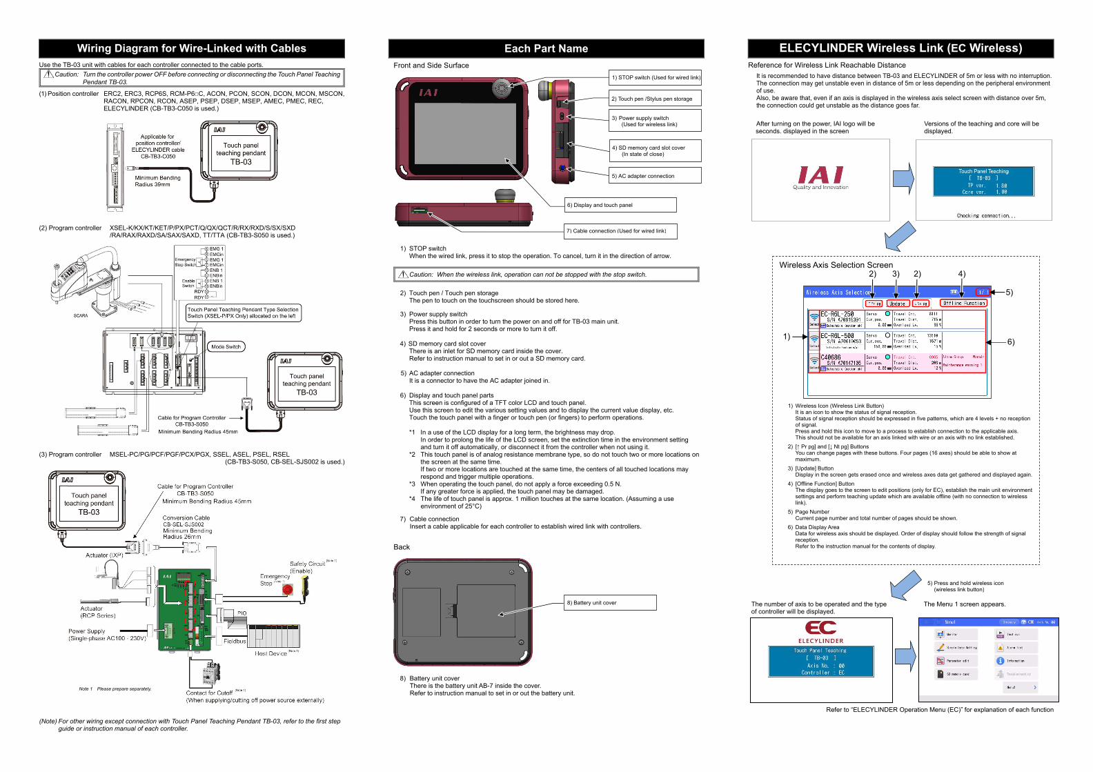
Wireless Axis Selection Screen
1) Wireless Icon (Wireless Link Button) It is an icon to show the status of signal reception. Status of signal reception should be expressed in five patterns, which are 4 levels + no reception of signal. Press and hold this icon to move to a process to establish connection to the applicable axis. This should not be available for an axis linked with wire or an axis with no link established.
2) [↑ Pr pg] and [↓ Nt pg] Buttons You can change pages with these buttons. Four pages (16 axes) should be able to show at maximum.
3) [Update] Button Display in the screen gets erased once and wireless axes data get gathered and displayed again.
4) [Offline Function] Button The display goes to the screen to edit positions (only for EC), establish the main unit environment settings and perform teaching update which are available offline (with no connection to wireless link).
5) Page Number Current page number and total number of pages should be shown.
6) Data Display Area Data for wireless axis should be displayed. Order of display should follow the strength of signal reception. Refer to the instruction manual for the contents of display.
Use the TB-03 unit with cables for each controller connected to the cable ports. Caution: Turn the controller power OFF before connecting or disconnecting the Touch Panel Teaching
Pendant TB-03.
(1) Position controller ERC2, ERC3, RCP6S, RCM-P6□C, ACON, PCON, SCON, DCON, MCON, MSCON, RACON, RPCON, RCON, ASEP, PSEP, DSEP, MSEP, AMEC, PMEC, REC, ELECYLINDER (CB-TB3-C050 is used.)
(2) Program controller XSEL-K/KX/KT/KET/P/PX/PCT/Q/QX/QCT/R/RX/RXD/S/SX/SXD /RA/RAX/RAXD/SA/SAX/SAXD, TT/TTA (CB-TB3-S050 is used.)
(3) Program controller MSEL-PC/PG/PCF/PGF/PCX/PGX, SSEL, ASEL, PSEL, RSEL
(CB-TB3-S050, CB-SEL-SJS002 is used.)
(Note) For other wiring except connection with Touch Panel Teaching Pendant TB-03, refer to the first step
guide or instruction manual of each controller.
Each Part Name Front and Side Surface
1) STOP switch
When the wired link, press it to stop the operation. To cancel, turn it in the direction of arrow.
Caution: When the wireless link, operation can not be stopped with the stop switch.
2) Touch pen / Touch pen storage
The pen to touch on the touchscreen should be stored here. 3) Power supply switch
Press this button in order to turn the power on and off for TB-03 main unit. Press it and hold for 2 seconds or more to turn it off.
4) SD memory card slot cover
There is an inlet for SD memory card inside the cover. Refer to instruction manual to set in or out a SD memory card.
5) AC adapter connection
It is a connector to have the AC adapter joined in. 6) Display and touch panel parts
This screen is configured of a TFT color LCD and touch panel. Use this screen to edit the various setting values and to display the current value display, etc. Touch the touch panel with a finger or touch pen (or fingers) to perform operations.
*1 In a use of the LCD display for a long term, the brightness may drop. In order to prolong the life of the LCD screen, set the extinction time in the environment setting
and turn it off automatically, or disconnect it from the controller when not using it. *2 This touch panel is of analog resistance membrane type, so do not touch two or more locations on
the screen at the same time. If two or more locations are touched at the same time, the centers of all touched locations may
respond and trigger multiple operations. *3 When operating the touch panel, do not apply a force exceeding 0.5 N. If any greater force is applied, the touch panel may be damaged. *4 The life of touch panel is approx. 1 million touches at the same location. (Assuming a use
environment of 25°C)
7) Cable connection Insert a cable applicable for each controller to establish wired link with controllers.
Back
8) Battery unit cover There is the battery unit AB-7 inside the cover. Refer to instruction manual to set in or out the battery unit.
ELECYLINDER Wireless Link (EC Wireless) Reference for Wireless Link Reachable Distance
It is recommended to have distance between TB-03 and ELECYLINDER of 5m or less with no interruption. The connection may get unstable even in distance of 5m or less depending on the peripheral environment of use. Also, be aware that, even if an axis is displayed in the wireless axis select screen with distance over 5m, the connection could get unstable as the distance goes far.
After turning on the power, IAI logo will be Versions of the teaching and core will be seconds. displayed in the screen displayed.
The number of axis to be operated and the type The Menu 1 screen appears. of controller will be displayed.
Refer to “ELECYLINDER Operation Menu (EC)” for explanation of each function
Wiring Diagram for Wire-Linked with Cables
5) Press and hold wireless icon (wireless link button)
3) 2) 4)
5)
2)
1) 6)
Note 1 Please prepare separately.
6) Display and touch panel
1) STOP switch (Used for wired link)
4) SD memory card slot cover (In state of close)
5) AC adapter connection
7) Cable connection (Used for wired link)
8) Battery unit cover
2) Touch pen /Stylus pen storage
3) Power supply switch (Used for wireless link)
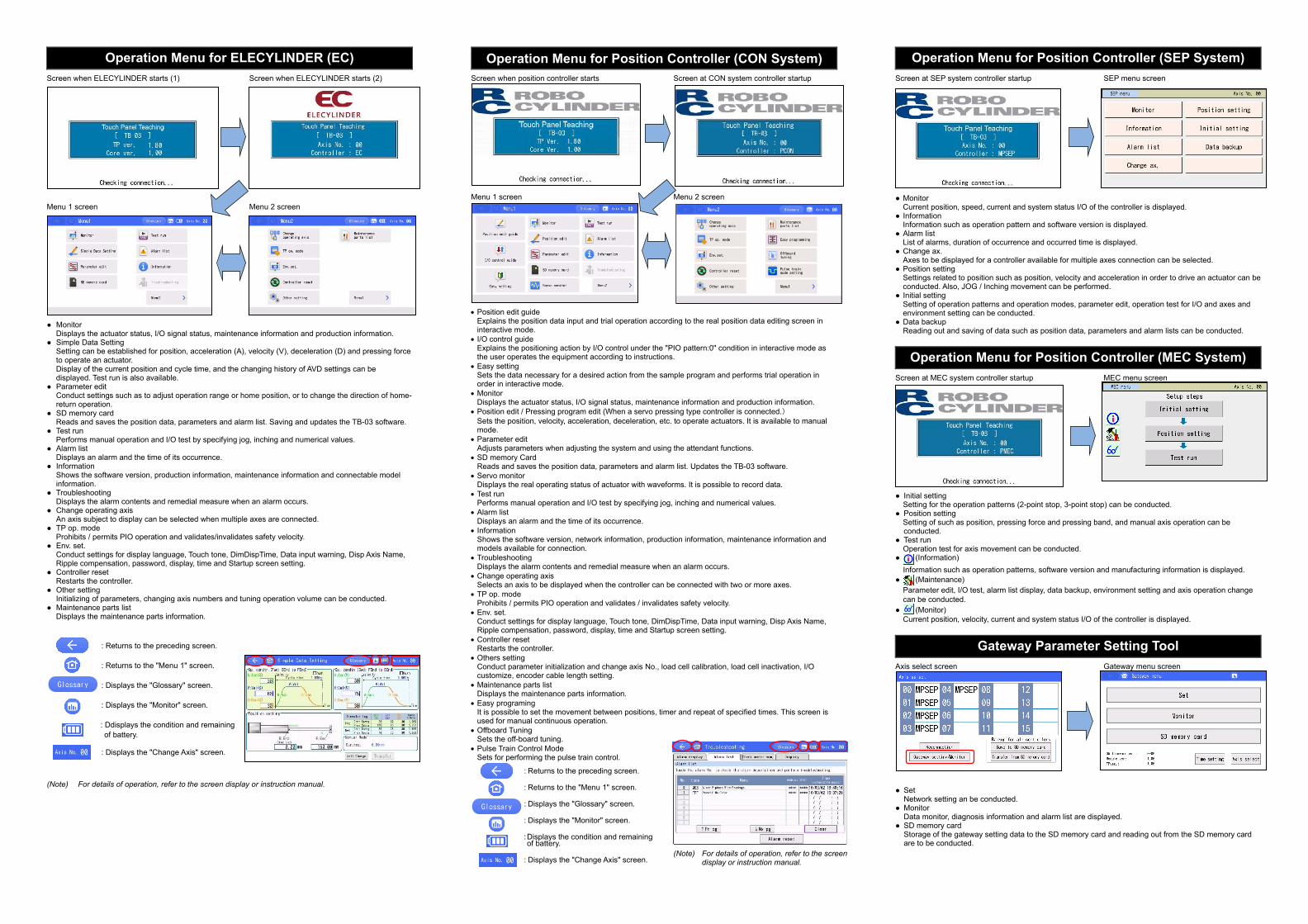
Operation Menu for ELECYLINDER (EC) Screen when ELECYLINDER starts (1) Screen when ELECYLINDER starts (2) Menu 1 screen Menu 2 screen ● Monitor
Displays the actuator status, I/O signal status, maintenance information and production information. ● Simple Data Setting
Setting can be established for position, acceleration (A), velocity (V), deceleration (D) and pressing force to operate an actuator. Display of the current position and cycle time, and the changing history of AVD settings can be displayed. Test run is also available.
● Parameter edit Conduct settings such as to adjust operation range or home position, or to change the direction of home-return operation.
● SD memory card Reads and saves the position data, parameters and alarm list. Saving and updates the TB-03 software.
● Test run Performs manual operation and I/O test by specifying jog, inching and numerical values.
● Alarm list Displays an alarm and the time of its occurrence.
● Information Shows the software version, production information, maintenance information and connectable model information.
● Troubleshooting Displays the alarm contents and remedial measure when an alarm occurs.
● Change operating axis An axis subject to display can be selected when multiple axes are connected.
● TP op. mode Prohibits / permits PIO operation and validates/invalidates safety velocity.
● Env. set. Conduct settings for display language, Touch tone, DimDispTime, Data input warning, Disp Axis Name, Ripple compensation, password, display, time and Startup screen setting.
● Controller reset Restarts the controller.
● Other setting Initializing of parameters, changing axis numbers and tuning operation volume can be conducted.
● Maintenance parts list Displays the maintenance parts information.
: Returns to the preceding screen.
: Returns to the "Menu 1" screen.
: Displays the "Glossary" screen.
: Displays the "Monitor" screen.
: Ddisplays the condition and remaining of battery.
: Displays the "Change Axis" screen.
(Note) For details of operation, refer to the screen display or instruction manual.
Operation Menu for Position Controller (CON System) Screen when position controller starts Screen at CON system controller startup Menu 1 screen Menu 2 screen
Position edit guide Explains the position data input and trial operation according to the real position data editing screen in interactive mode.
I/O control guide Explains the positioning action by I/O control under the "PIO pattern:0" condition in interactive mode as the user operates the equipment according to instructions.
Easy setting Sets the data necessary for a desired action from the sample program and performs trial operation in order in interactive mode.
Monitor Displays the actuator status, I/O signal status, maintenance information and production information.
Position edit / Pressing program edit (When a servo pressing type controller is connected.) Sets the position, velocity, acceleration, deceleration, etc. to operate actuators. It is available to manual mode.
Parameter edit Adjusts parameters when adjusting the system and using the attendant functions.
SD memory Card Reads and saves the position data, parameters and alarm list. Updates the TB-03 software.
Servo monitor Displays the real operating status of actuator with waveforms. It is possible to record data.
Test run Performs manual operation and I/O test by specifying jog, inching and numerical values.
Alarm list Displays an alarm and the time of its occurrence.
Information Shows the software version, network information, production information, maintenance information and models available for connection.
Troubleshooting Displays the alarm contents and remedial measure when an alarm occurs.
Change operating axis Selects an axis to be displayed when the controller can be connected with two or more axes.
TP op. mode Prohibits / permits PIO operation and validates / invalidates safety velocity.
Env. set. Conduct settings for display language, Touch tone, DimDispTime, Data input warning, Disp Axis Name, Ripple compensation, password, display, time and Startup screen setting.
Controller reset Restarts the controller.
Others setting Conduct parameter initialization and change axis No., load cell calibration, load cell inactivation, I/O customize, encoder cable length setting.
Maintenance parts list Displays the maintenance parts information.
Easy programing It is possible to set the movement between positions, timer and repeat of specified times. This screen is used for manual continuous operation.
Offboard Tuning Sets the off-board tuning.
Pulse Train Control Mode Sets for performing the pulse train control.
: Returns to the preceding screen.
: Returns to the "Menu 1" screen.
: Displays the "Glossary" screen.
: Displays the "Monitor" screen.
: Displays the condition and remaining of battery.
: Displays the "Change Axis" screen.
Operation Menu for Position Controller (SEP System) Screen at SEP system controller startup SEP menu screen
● Monitor Current position, speed, current and system status I/O of the controller is displayed.
● Information Information such as operation pattern and software version is displayed.
● Alarm Iist List of alarms, duration of occurrence and occurred time is displayed.
● Change ax. Axes to be displayed for a controller available for multiple axes connection can be selected.
● Position setting Settings related to position such as position, velocity and acceleration in order to drive an actuator can be conducted. Also, JOG / Inching movement can be performed.
● Initial setting Setting of operation patterns and operation modes, parameter edit, operation test for I/O and axes and environment setting can be conducted.
● Data backup Reading out and saving of data such as position data, parameters and alarm lists can be conducted.
Operation Menu for Position Controller (MEC System) Screen at MEC system controller startup MEC menu screen ● Initial setting
Setting for the operation patterns (2-point stop, 3-point stop) can be conducted. ● Position setting
Setting of such as position, pressing force and pressing band, and manual axis operation can be conducted.
● Test run Operation test for axis movement can be conducted.
● (Information) Information such as operation patterns, software version and manufacturing information is displayed.
● (Maintenance) Parameter edit, I/O test, alarm list display, data backup, environment setting and axis operation change can be conducted.
● (Monitor) Current position, velocity, current and system status I/O of the controller is displayed.
Gateway Parameter Setting Tool Axis select screen Gateway menu screen
● Set
Network setting an be conducted. ● Monitor
Data monitor, diagnosis information and alarm list are displayed. ● SD memory card
Storage of the gateway setting data to the SD memory card and reading out from the SD memory card are to be conducted.
(Note) For details of operation, refer to the screen
display or instruction manual.
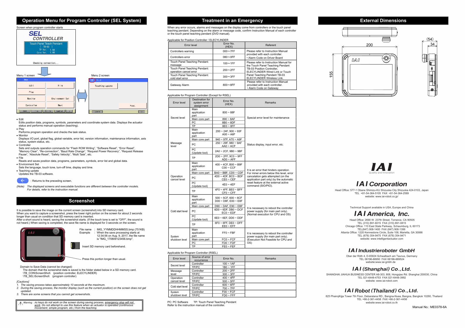
Operation Menu for Program Controller (SEL System) Screen when program controller starts
Menu 1 screen Menu 2 screen
Edit Edits position data, programs, symbols, parameters and coordinate system data. Displays the actuator status and performs manual operation (teaching).
Play Performs program operation and checks the task status.
Monitor Displays I/O port, global flag, global variable, error list, version information, maintenance information, axis status, system status, etc.
Controller Sets and outputs operation commands for “Flash ROM Writing”, “Software Reset”, “Error Reset”, “Memory Clear”, “Re-connection”, “Baud Rate Change”, “Request Power Recovery”, “Request Release Pause”, “Absolute Reset”, “Safety Velocity”, “Multi Task”, etc.
File Reads and saves position data, programs, parameters, symbols, error list and global data.
Environment Set Sets the language, touch tone, turn-off time, display and time.
Teaching update Updates the TB-03 software.
: Returns to the preceding screen. (Note) The displayed screens and executable functions are different between the controller models.
For details, refer to the instruction manual.
Screenshot It is possible to save the image on the current screen (screenshot) into SD memory card. When you want to capture a screenshot, press the lower right portion on the screen for about 2 seconds longer than usual on condition that SD memory card is inserted. After a short sound is heard, saving the screenshot starts. (If the touch tone is set to "OFF", the sound is not heard.) When saving is completed, the save file name is displayed for 3 seconds on the screen.
File name : IMG_YYMMDDHHMMSS.bmp (751KB) Example : When the save processing starts at
12:34:56 on Aug. 9, 2017, the file name is "IMG_170809123456.bmp".
Domain to Save Data (cannot be changed)
The domain that the screenshot data is saved is the folder stated below in a SD memory card. \TB_CON\ScreenShot\ (position controller, ELECYLINDER) \TB_SEL\ScreenShot\ (program controller)
[Cautions] 1. The saving process takes approximately 10 seconds at the maximum. 2. During the saving process, the monitor display (such as the current position) on the screen does not get
updated. 3. There are some screens that you cannot get screenshots.
Treatment in an Emergency When any error occurs, alarms and messages on the display come from controllers or the touch panel teaching pendant. Depending on the alarm or message code, confirm Instruction Manual of each controller or the touch panel teaching pendant (DVD manual). Applicable for Position Controller / ELECYLINDER
Error level Error No. (HEX) Referent
Controllers warning 000~7FF Please refer to Instruction Manual provided with each controller. • Alarm Code on Driver Board Controllers error 080~0FF
Touch Panel Teaching Pendant: message 100~1FF Please refer to Instruction Manual for
the Touch Panel Teaching Pendant TB-03 Position Controller, ELECYLINDER Wired Link or Touch Panel Teaching Pendant TB-03 ELECYLINDER Wireless Link.
Touch Panel Teaching Pendant: operation cancel error 200~2FF
Touch Panel Teaching Pendant: cold start error 300~3FF
Gateway Alarm 800~8FF Please refer to Instruction Manual provided with each controller. • Alarm Code on Gateway
Applicable for Program Controller (Except for RSEL)
Error level Destination for system error assignment
Error No. (HEX) Remarks
Secret level
Main application part
800 ~ 88F
Special error level for maintenance Main core part 890 ~ 8AF PC 8B0 ~ 8DF TP 8E0 ~ 8FF
Message level
Main application part
200 ~ 24F, 900 ~ 93F A00 ~ A6F
Status display, input error, etc.
Main core part 940 ~ 97F, A70 ~ A9F
PC 250 ~ 29F, 980 ~ 9AF AA0 ~ ACF
PC (Update tool) 2A0 ~ 2CF, 9B0 ~ 9BF
TP 2D0 ~ 2FF, 9C0 ~ 9FF AD0 ~ AFF
Operation cancel level
Main application part
400 ~ 4CF, B00 ~ B9F C00 ~ CCF
It is an error that hinders operation. For miner errors below this level, error cancelation gets attempted (on the application part only) by the automatic reset feature at the external active command (SIO/PIO).
Main core part BA0 ~ BBF, CD0 ~ CDF
PC 4D0 ~ 4DF, BC0 ~ BDF CE0 ~ CEF
PC (Update tool) 4E0 ~ 4EF
TP 4F0 ~ 4FF, BE0 ~ BFF CF0 ~ CFF
Cold start level
Main application part
500 ~ 5CF, 600 ~ 6CF D00 ~ D8F, E00 ~ E8F
It is necessary to reboot the controller power supply (for main part only). (Normal execution for CPU and OS)
Main core part D90 ~ DAF, E90 ~ EBF
PC 6D0 ~ 6DF, DB0 ~ DCF EC0 ~ EDF
PC (Update tool) 6E0 ~ 6EF, DD0 ~ DDF
TP 6F0 ~ 6FF, DE0 ~ DFF EE0 ~ EFF
System shutdown level
Main application part
FF0 ~ FBF It is necessary to reboot the controller power supply (for main part only). (Execution Not Feasible for CPU and OS)
Main core part FC0 ~ FCF PC FD0 ~ FDF TP FE0 ~ FEF
Applicable for Program Controller (RSEL)
Error level Source of error occurrence Error No. Remarks
Secret level Controller 100 ~ 1AF TP/PC 1B0 ~ 1FF Message level
Controller 200 ~ 2FF TP/PC 300 ~ 3FF Operation cancel level
Controller 400 ~ 4FF TP/PC 500 ~ 5FF
Cold start level Controller 600 ~ 6FF TP/PC 700 ~ 7FF System shutdown level
Controller F00 ~ FCF TP/PC FD0 ~ FFF PC: PC Software TP: Touch Panel Teaching Pendant Refer to the instruction manual of the controller.
Head Office: 577-1 Obane Shimizu-KU Shizuoka City Shizuoka 424-0103, JapanTEL +81-54-364-5105 FAX +81-54-364-2589
website: www.iai-robot.co.jp/
Ober der Röth 4, D-65824 Schwalbach am Taunus, GermanyTEL 06196-88950 FAX 06196-889524
SHANGHAI JIAHUA BUSINESS CENTER A8-303, 808, Hongqiao Rd. Shanghai 200030, ChinaTEL 021-6448-4753 FAX 021-6448-3992
website: www.iai-robot.com
Technical Support available in USA, Europe and China
Head Office: 2690 W. 237th Street, Torrance, CA 90505TEL (310) 891-6015 FAX (310) 891-0815
Chicago Office: 110 East State Parkway, Schaumburg, IL 60173TEL(847) 908-1400 FAX (847) 908-1399
TEL (678) 354-9470 FAX (678) 354-9471website: www.intelligentactuator.com
Atlanta Office: 1220 Kennestone Circle, Suite 108, Marietta, GA 30066
825 PhairojKijja Tower 7th Floor, Debaratana RD., Bangna-Nuea, Bangna, Bangkok 10260, ThailandTEL +66-2-361-4458 FAX +66-2-361-4456
website:www.iai-gmbh.de
website:www.iai-robot.co.th
External Dimensions
Insert SD memory card beforehand. Press this portion longer than usual.
Warning : As keys do not work on the screen during saving process, emergency stop will not work. Do not attempt to use this feature when an actuator is operated (continuous movement, simple program, etc.) from the teaching. Manual No.: ME0378-6A