Embed Size (px)
Citation preview
8/9/13 TerraView™
submittals.nfpa.org/TerraViewWeb/ViewerPage.jsp 1/140
First Revision No. 63-NFPA 850-2013 [ Global Input ]
Change the number 1890 L/min to 1893 L/min throughout the document.
Submitter Information Verification
Submitter Full Name: [ Not Specified ]
Organization: [ Not Specified ]
Street Address:
City:
State:
Zip:
Submittal Date: Wed May 22 14:01:21 EDT 2013
Committee Statement
Committee Statement: Editorial
Response Message:
8/9/13 TerraView™
submittals.nfpa.org/TerraViewWeb/ViewerPage.jsp 2/140
First Revision No. 104-NFPA 850-2013 [ Section No. 1.1 ]
1.1 Scope.
This document provides recommendations for fire prevention and fire protection for electricgenerating plants and high voltage direct current converter stations, except as follows:Nuclear power plants are addressed in NFPA 805, Performance-Based Standard for FireProtection for Light Water Reactor Electric Generating Plants; hydroelectric plants areaddressed in NFPA 851 , Recommended Practice for Fire Protection for HydroelectricGenerating Plants ; and fuel cells are addressed in NFPA 853, Standard for theInstallation of Stationary Fuel Cell Power Systems.
Submitter Information Verification
Submitter Full Name: [ Not Specified ]
Organization: [ Not Specified ]
Street Address:
City:
State:
Zip:
Submittal Date: Mon Jun 03 10:08:27 EDT 2013
Committee Statement
Committee Statement: NFPA 851 has been withdrawn and incorporated into NFPA 850.
Response Message:
First Revision No. 1-NFPA 850-2013 [ Section No. 2.2 ]
2.2 NFPA Publications.
National Fire Protection Association, 1 Batterymarch Park, Quincy, MA 02169-7471.
NFPA 1, Fire Code, 2009 2015 edition.
NFPA 10, Standard for Portable Fire Extinguishers, 2010 2013 edition.
NFPA 11, Standard for Low-, Medium-, and High-Expansion Foam, 2010 2014 edition.
NFPA 12, Standard on Carbon Dioxide Extinguishing Systems, 2008 2015 edition.
NFPA 12A, Standard on Halon 1301 Fire Extinguishing Systems, 2009 2015 edition.
NFPA 13, Standard for the Installation of Sprink ler Systems, 2010 2013 edition.
NFPA 14, Standard for the Installation of Standpipe and Hose Systems, 2010 2013edition.
8/9/13 TerraView™
submittals.nfpa.org/TerraViewWeb/ViewerPage.jsp 3/140
NFPA 15, Standard for Water Spray Fixed Systems for Fire Protection, 2007 2012edition.
NFPA 16, Standard for the Installation of Foam-Water Sprink ler and Foam-Water SpraySystems, 2007 2015 edition.
NFPA 17, Standard for Dry Chemical Extinguishing Systems, 2009 2013 edition.
NFPA 20, Standard for the Installation of Stationary Pumps for Fire Protection,2010 2013 edition.
NFPA 22, Standard for Water Tanks for Private Fire Protection, 2008 2015 edition.
NFPA 24, Standard for the Installation of Private Fire Service Mains and TheirAppurtenances, 2010 2013 edition.
NFPA 25, Standard for the Inspection, Testing, and Maintenance of Water-Based FireProtection Systems, 2008 2014 edition.
NFPA 30, Flammable and Combustible Liquids Code, 2008 2015 edition.
NFPA 30A, Code for Motor Fuel Dispensing Facilities and Repair Garages, 2008 2012edition.
NFPA 31, Standard for the Installation of Oil-Burning Equipment, 2006 2015 edition.
NFPA 37, Standard for the Installation and Use of Stationary Combustion Engines andGas Turbines, 2010 2014 edition.
NFPA 51B, Standard for Fire Prevention During Welding, Cutting, and Other Hot Work ,2009 2014 edition.
NFPA 54, National Fuel Gas Code, 2009 2015 edition.
NFPA 55, Compressed Gases and Cryogenic Fluids Code, 2010 2013 edition.
NFPA 56 Standard for Fire and Explosion Prevention During Cleaning and Purging ofFlammable Gas Piping Systems, 2014 edition.
NFPA 58, Liquefied Petroleum Gas Code, 2008 2014 edition.
NFPA 59, Utility LP-Gas Plant Code, 2008 2015 edition.
NFPA 59A, Standard for the Production, Storage, and Handling of Liquefied Natural Gas(LNG), 2009 2013 edition.
NFPA 61, Standard for the Prevention of Fires and Dust Explosions in Agricultural andFood Processing Facilities, 2008 2013 edition.
NFPA 68, Standard on Explosion Protection by Deflagration Venting, 2007 2013 edition.
NFPA 69, Standard on Explosion Prevention Systems, 2008 2014 edition.
NFPA 70®, National Electrical Code®, 2008 2014 edition.
NFPA 72®, National Fire Alarm and Signaling Code, 2010 2013 edition.
NFPA 75, Standard for the Protection of Information Technology Equipment, 2009 2013edition.
NFPA 77, Recommended Practice on Static Electricity, 2007 2014 edition.
NFPA 80, Standard for Fire Doors and Other Opening Protectives, 2010 2013 edition.
NFPA 80A, Recommended Practice for Protection of Buildings from Exterior FireExposures, 2007 2012 edition.
8/9/13 TerraView™
submittals.nfpa.org/TerraViewWeb/ViewerPage.jsp 4/140
NFPA 85, Boiler and Combustion Systems Hazards Code, 2007 2012 edition.
NFPA 86, Standard for Ovens and Furnaces, 2007 2015 edition.
NFPA 90A, Standard for the Installation of Air-Conditioning and Ventilating Systems,2009 2015 edition.
NFPA 90B, Standard for the Installation of Warm Air Heating and Air-ConditioningSystems, 2009 201 2 edition.
NFPA 91 92 , Standard for Exhaust Systems for Air Conveying of Vapors, Gases, Mists,and Noncombustible Particulate Solids Smoke Control Systems , 2010 2012 edition.
NFPA 92A 96 , Standard for Smoke-Control Systems Utilizing Barriers and PressureDifferences Ventilation Control and Fire Protection of Commercial Cook ing Operations ,2009 2014 edition.
NFPA 101®, Life Safety Code®, 2009 2015 edition.
NFPA 110, Standard for Emergency and Standby Power Systems, 2010 2013 edition.
NFPA 120, Standard for Fire Prevention and Control in Coal Mines, 2015 edition.
NFPA 204, Standard for Smoke and Heat Venting, 2007 2015 edition.
NFPA 214, Standard on Water-Cooling Towers, 2005 2011 edition.
NFPA 220, Standard on Types of Building Construction, 2009 2014 edition.
NFPA 241, Standard for Safeguarding Construction, Alteration, and DemolitionOperations, 2009 2013 edition.
NFPA 251, Standard Methods of Tests of Fire Resistance of Building Construction andMaterials, 2006 edition.
NFPA 252, Standard Methods of Fire Tests of Door Assemblies, 2008 2012 edition.
NFPA 253, Standard Method of Test for Critical Radiant Flux of Floor Covering SystemsUsing a Radiant Heat Energy Source, 2006 2015 edition.
NFPA 257, Standard on Fire Test for Window and Glass Block Assemblies, 2007 2012edition.
NFPA 259, Standard Test Method for Potential Heat of Building Materials, 2008 2013edition.
NFPA 497, Recommended Practice for the Classification of Flammable Liquids, Gases,or Vapors and of Hazardous (Classified) Locations for Electrical Installations in ChemicalProcess Areas, 2008 2012 edition.
NFPA 551 501A , Guide for the Evaluation of Fire Risk Assessments Standard for FireSafety Criteria for Manufactured Home Installations, Sites, and Communities, 2010 2013edition.
NFPA 600, Standard on Industrial Fire Brigades, 2010 2015 edition.
NFPA 601, Standard for Security Services in Fire Loss Prevention, 2010 2015 edition.
NFPA 654, Standard for the Prevention of Fire and Dust Explosions from theManufacturing, Processing, and Handling of Combustible Particulate Solids, 2006 2013edition.
NFPA 664, Standard for the Prevention of Fires and Explosions in Wood Processing andWoodwork ing Facilities, 2007 2012 edition.
NFPA 701, Standard Methods of Fire Tests for Flame Propagation of Textiles and Films,
8/9/13 TerraView™
submittals.nfpa.org/TerraViewWeb/ViewerPage.jsp 5/140
2010 2015 edition.
NFPA 704, Standard System for the Identification of the Hazards of Materials forEmergency Response, 2007 2012 edition.
NFPA 750, Standard on Water Mist Fire Protection Systems, 2010 2014 edition.
NFPA 780, Standard for the Installation of Lightning Protection Systems, 2008 2014edition.
NFPA 805, Performance-Based Standard for Fire Protection for Light Water ReactorElectric Generating Plants, 2010 2015 edition.
NFPA 851, Recommended Practice for Fire Protection for Hydroelectric GeneratingPlants, 2010 edition.
NFPA 853, Standard for the Installation of Stationary Fuel Cell Power Systems,2010 2015 edition.
NFPA 1142, Standard on Water Supplies for Suburban and Rural Fire Fighting, 2012edition.
NFPA 1143, Standard for Wildland Fire Management, 2009 2014 edition.
NFPA 1144, Standard for Reducing Structure Ignition Hazards from Wildland Fire,2008 2013 edition.
NFPA 1221, Standard for the Installation, Maintenance, and Use of Emergency ServicesCommunications Systems, 2010 2013 edition.
NFPA 1901, Standard for Automotive Fire Apparatus, 2009 edition.
NFPA 1962, Standard for the Inspection, Care, and Use of Fire Hose, Couplings, andNozzles and the Service Testing of Fire Hose, 2008 2013 edition.
NFPA 1971, Standard on Protective Ensembles for Structural Fire Fighting and ProximityFire Fighting, 2007 2013 edition.
NFPA 2001, Standard on Clean Agent Fire Extinguishing Systems, 2008 2012 edition.
NFPA 2010, Standard for Fixed Aerosol Fire-Extinguishing Systems, 2015 edition.
NFPA, Fire Protection Handbook, 2008, 20th edition.
SFPE, Engineering Guide to Fire Risk Assessment, 2006 edition.
SFPE, Handbook of Fire Protection Engineering, 2008, 4th edition.
Submitter Information Verification
Submitter Full Name: [ Not Specified ]
Organization: [ Not Specified ]
Street Address:
City:
State:
Zip:
Submittal Date: Thu May 16 11:22:17 EDT 2013
Committee Statement
8/9/13 TerraView™
submittals.nfpa.org/TerraViewWeb/ViewerPage.jsp 6/140
CommitteeStatement:
Revised edition dates to comply with the manual of styles. Removed reference toNFPA 92A as it has been withdrawn and incorporated into NFPA 92. Addedreference to NFPA 92 Standard for Smoke Control Systems. Removed reference toNFPA 251 as the document has been withdrawn and the industry now refers toASTM E119 or UL 263. Removed reference to NFPA 851 as it has been incorporatedinto NFPA 850.Added reference to NFPA 96, 120, 501A and 1901 based on theincorporation of NFPA 851.
ResponseMessage:
Public Input No. 11-NFPA 850-2012 [Section No. 2.2]
First Revision No. 7-NFPA 850-2013 [ Section No. 2.3.2 ]
2.3.2 API Publications.
American Petroleum Institute, 1220 L Street, NW, Washington, DC 20005-4070.
API 500, Recommended Practice for Classification of Locations for ElectricalInstallations at Petroleum Facilities Classified as Class I, Division I and Division II,2002 2012 .
API 505, Recommended Practice for Classification of Locations for ElectricalInstallations at Petroleum Facilities Classified as Class I, Zone 0 and Zone 2,1997 2002 .
API 537, Flare Details for General Refinery and Petrochemical Service, 2008.
API 2218, Fireproofing Practices in Petroleum and Petrochemical Processing Plants,1999 2010 .
API RP 521, Guide for Pressure Relieving and Depressurizing Systems, 2007.
API RP 941, Steels for Hydrogen Service at Elevated Temperatures and Pressures inPetroleum Refineries and Petrochemical Plants, 2004 2008 .
Submitter Information Verification
Submitter Full Name: [ Not Specified ]
Organization: [ Not Specified ]
Street Address:
City:
State:
Zip:
Submittal Date: Thu May 16 15:21:50 EDT 2013
Committee Statement
Committee Statement: Editorially revised reference dates to comply with the manual of style.
Response Message:

8/9/13 TerraView™
submittals.nfpa.org/TerraViewWeb/ViewerPage.jsp 7/140
First Revision No. 3-NFPA 850-2013 [ Section No. 2.3.3 ]
2.3.3 ASME Publications.
American Society of Mechanical Engineers, Three Park Avenue, New York, NY 10016-5990.
ASME B31.1, Power Piping, 1998 2012 .
ASME B31.3, Process Piping, 2002 2012 .
Submitter Information Verification
Submitter Full Name: [ Not Specified ]
Organization: [ Not Specified ]
Street Address:
City:
State:
Zip:
Submittal Date: Thu May 16 14:12:09 EDT 2013
Committee Statement
Committee Statement: Editorially revised reference dates to comply with the manual of style.
Response Message:
8/9/13 TerraView™
submittals.nfpa.org/TerraViewWeb/ViewerPage.jsp 8/140
First Revision No. 2-NFPA 850-2013 [ Section No. 2.3.4 ]
2.3.4 ASTM Publications.
ASTM International, 100 Barr Harbor Drive, P.O. Box C700, West Conshohocken, PA19428-2959.
ASTM D 92, Standard Test Method for Flash and Fire Points by Cleveland Open CupTester, 2003 2012b .
ASTM D 448, Standard Classification for Sizes of Aggregate for Road and BridgeConstruction, 2003 2012 .
ASTM E 84, Standard Test Method for Surface Burning Characteristics of BuildingMaterials, 2009 2012c .
ASTM E 108, Standard Test Methods for Fire Tests of Roof Coverings, 2007a 2011 .
ASTM E 119, Standard Test Methods for Fire Tests of Building Construction andMaterials , 2012.
ASTM E 136, Standard Test Method for Behavior of Materials in a Vertical Tube Furnaceat 750°C, 1994 2012 .
ASTM E 814, Standard Test Method for Fire Tests of Penetration Firestop Systems,2009 2011 .
ASTM E 1248, Standard Practice for Shredder Explosion Protection, 2009 .
ASTM SI 10, American National Standard for Use of the International System of Units(SI): The Modern Metric System Metric Practice , 1997 2010 .
Submitter Information Verification
Submitter Full Name: [ Not Specified ]
Organization: [ Not Specified ]
Street Address:
City:
State:
Zip:
Submittal Date: Thu May 16 13:56:46 EDT 2013
Committee Statement
CommitteeStatement:
Editorially revised reference dates to comply with the manual of style.Updated titles.
Response Message:
8/9/13 TerraView™
submittals.nfpa.org/TerraViewWeb/ViewerPage.jsp 9/140
First Revision No. 4-NFPA 850-2013 [ Section No. 2.3.5 ]
2.3.5 IEC Publications.
International Electrotechnical Commission, 3, rue de Varembé, P.O. Box 131, CH-1211Geneva 20, Switzerland.
IEC 62305 TR 61400-24, Wind Turbine Generator Systems , 2002. , Protection AgainstLightning , 2003 .
Submitter Information Verification
Submitter Full Name: [ Not Specified ]
Organization: [ Not Specified ]
Street Address:
City:
State:
Zip:
Submittal Date: Thu May 16 14:18:08 EDT 2013
Committee Statement
CommitteeStatement:
IEC TR 61400-24 has been withdrawn and therefore removed as areference.
Response Message:
8/9/13 TerraView™
submittals.nfpa.org/TerraViewWeb/ViewerPage.jsp 10/140
First Revision No. 5-NFPA 850-2013 [ Section No. 2.3.6 ]
2.3.6 IEEE Publications.
IEEE, Three Park Avenue, 17th Floor, New York, NY 10016-5997.
IEEE C37.20.7, Guide for Testing Metal-Enclosed Switchgear Rated Up to 38 kV forInternational Internal Arcing Faults, 2007.
IEEE 383, Standard for Type Test of Class IE Electric Cables, Field Splices andConnections for Nuclear Power Generating Stations , 1974.
IEEE 484, Recommended Practice for Installation Design and Installation ofLarge Vented Lead—Acid Lead-Acid Storage Batteries for Generating Stations andSubstations Stationary Applications , 1987 2002 .
IEEE 634, Testing of Fire Rated Penetration Seals Standard for Cable-Penetration FireStop Qualification Test , 1978 2004 .
IEEE 1202, Standard for Flame-Propagation Testing of Wire and Cable, 2006.
Submitter Information Verification
Submitter Full Name: [ Not Specified ]
Organization: [ Not Specified ]
Street Address:
City:
State:
Zip:
Submittal Date: Thu May 16 14:23:09 EDT 2013
Committee Statement
CommitteeStatement:
Revised reference dates to comply with the manual of style. Updated titles.Removed withdrawn document and inserted new reference.
ResponseMessage:

8/9/13 TerraView™
submittals.nfpa.org/TerraViewWeb/ViewerPage.jsp 11/140
First Revision No. 28-NFPA 850-2013 [ Section No. 2.3.7 ]
2.3.7 UL Publications.
Underwriters Laboratories Inc., 333 Pfingsten Road, Northbrook, IL 60062-2096.
ANSI/UL 263, Standard for Fire Tests of Building Construction and Materials , 2011.
ANSI/UL 723, Test for Surface Burning Characteristics of Building Materials, 2008,revised 2010 .
ANSI/UL 790, Tests for Fire Resistance of Roof Covering Materials 2004, revised 2008.
ANSI/UL 900, Standard for Safety Test Performance of Air Filters, 2004, Revised2007 revised 2011 .
ANSI/UL 1479, Standard for Fire Tests of Through-Penetration Firestops, 2003, Revised2008 revised 2010 .
UL 790, Tests for Fire Resistance of Roof Covering Materials , 2004 .
ANSI/ UL 1709, Standard for Rapid Rise Fire Tests of Protection Materials for StructuralSteel, 2005 2011 .
Submitter Information Verification
Submitter Full Name: [ Not Specified ]
Organization: [ Not Specified ]
Street Address:
City:
State:
Zip:
Submittal Date: Wed May 22 08:18:24 EDT 2013
Committee Statement
CommitteeStatement:
Add ANSI approval designation to ANSI/UL 790 and ANSI/UL 1709, and updatereferenced standards to most recent edition as indicated.
ResponseMessage:
Public Input No. 18-NFPA 850-2012 [Section No. 2.3.7]

8/9/13 TerraView™
submittals.nfpa.org/TerraViewWeb/ViewerPage.jsp 12/140
First Revision No. 29-NFPA 850-2013 [ Section No. 2.3.8 ]
2.3.8 U.S. Government Publications.
U.S. Government Printing Office, Washington, DC 20402.
OSHA 29 CFR 1910.146, “Permit Required Confined Space Standard,” U.S. Departmentof Labor, 2010.
Title 29, Code of Federal Regulations CFR , Part 1910.156, “Fire Brigades,” 1986 2008 .
Submitter Information Verification
Submitter Full Name: [ Not Specified ]
Organization: [ Not Specified ]
Street Address:
City:
State:
Zip:
Submittal Date: Wed May 22 08:23:22 EDT 2013
Committee Statement
Committee Statement: Revised reference dates to comply with the manual of style.
Response Message:
8/9/13 TerraView™
submittals.nfpa.org/TerraViewWeb/ViewerPage.jsp 13/140
First Revision No. 6-NFPA 850-2013 [ Section No. 2.4 ]
2.4 References for Extracts in Recommendations Sections.
NFPA 30, Flammable and Combustible Liquids Code, 2008 2015 edition.
NFPA 101®, Life Safety Code®, 2009 2015 edition.
NFPA 220, Standard on Types of Building Construction, 2009 2015 edition.
NFPA 801, Standard for Fire Protection for Facilities Handling Radioactive Materials,2008 2014 edition.
NFPA 851, Recommended Practice for Fire Protection for Hydroelectric GeneratingPlants, 2010 edition.
NFPA 5000®, Building Construction and Safety Code®, 2009 2015 edition.
Submitter Information Verification
Submitter Full Name: [ Not Specified ]
Organization: [ Not Specified ]
Street Address:
City:
State:
Zip:
Submittal Date: Thu May 16 14:42:32 EDT 2013
Committee Statement
CommitteeStatement:
Revised reference dates to comply with the manual of style. Removed referenceto NFPA 851 as it has been incorporated into NFPA 850.
ResponseMessage:
8/9/13 TerraView™
submittals.nfpa.org/TerraViewWeb/ViewerPage.jsp 14/140
First Revision No. 15-NFPA 850-2013 [ New Section after 3.3.2 ]
3.3.3 Combustible.
Capable of undergoing combustion.
Submitter Information Verification
Submitter Full Name: [ Not Specified ]
Organization: [ Not Specified ]
Street Address:
City:
State:
Zip:
Submittal Date: Tue May 21 14:13:53 EDT 2013
Committee Statement
CommitteeStatement:
Definition of combustible has been incorporated from NFPA 851 intoNFPA 850.
Response Message:
8/9/13 TerraView™
submittals.nfpa.org/TerraViewWeb/ViewerPage.jsp 15/140
First Revision No. 8-NFPA 850-2013 [ Section No. 3.3.7 ]
3.3.8 Fire Barrier.
A continuous membrane or a membrane with discontinuities created by protectedopenings with a specified fire protection rating, where such membrane is designed andconstructed with a specified fire resistance rating to limit the spread of fire, that alsorestricts the movement of smoke. [101, 2009 2015 ]
Submitter Information Verification
Submitter Full Name: [ Not Specified ]
Organization: [ Not Specified ]
Street Address:
City:
State:
Zip:
Submittal Date: Thu May 16 15:28:13 EDT 2013
Committee Statement
Committee Statement: Revised reference date to align with Chapter 2 reference.
Response Message:

8/9/13 TerraView™
submittals.nfpa.org/TerraViewWeb/ViewerPage.jsp 16/140
First Revision No. 13-NFPA 850-2013 [ Section No. 3.3.8 ]
3.3.9 Fire Loading.
The amount of combustibles present in a given area, expressed in Btu/ft2 (kJ/m2). [ 851,2010]
Submitter Information Verification
Submitter Full Name: [ Not Specified ]
Organization: [ Not Specified ]
Street Address:
City:
State:
Zip:
Submittal Date: Fri May 17 08:00:17 EDT 2013
Committee Statement
CommitteeStatement:
NFPA 851 has been withdrawn and incorporated into NFPA 850. Therefore, theextract reference is no longer needed.
ResponseMessage:

8/9/13 TerraView™
submittals.nfpa.org/TerraViewWeb/ViewerPage.jsp 17/140
First Revision No. 9-NFPA 850-2013 [ Section No. 3.3.9 ]
3.3.10 Fire Point.
The lowest temperature at which a liquid will ignite and achieve sustained burning whenexposed to a test flame in accordance with ASTM D 92, Standard Test Method for Flashand Fire Points by Cleveland Open Cup Tester. [30, 2008 2015 ]
Submitter Information Verification
Submitter Full Name: [ Not Specified ]
Organization: [ Not Specified ]
Street Address:
City:
State:
Zip:
Submittal Date: Fri May 17 07:54:24 EDT 2013
Committee Statement
Committee Statement: Revised reference date to align with Chapter 2 reference.
Response Message:
8/9/13 TerraView™
submittals.nfpa.org/TerraViewWeb/ViewerPage.jsp 18/140
First Revision No. 10-NFPA 850-2013 [ Section No. 3.3.10 ]
3.3.11 Fire Prevention.
Measures directed toward avoiding the inception of fire. [801, 2008 2014 ]
Submitter Information Verification
Submitter Full Name: [ Not Specified ]
Organization: [ Not Specified ]
Street Address:
City:
State:
Zip:
Submittal Date: Fri May 17 07:56:25 EDT 2013
Committee Statement
Committee Statement: Revised reference date to align with Chapter 2 reference.
Response Message:

8/9/13 TerraView™
submittals.nfpa.org/TerraViewWeb/ViewerPage.jsp 19/140
First Revision No. 11-NFPA 850-2013 [ Section No. 3.3.11 ]
3.3.12 Fire Protection.
Methods of providing for fire control or fire extinguishment. [801, 2008 2014 ]
Submitter Information Verification
Submitter Full Name: [ Not Specified ]
Organization: [ Not Specified ]
Street Address:
City:
State:
Zip:
Submittal Date: Fri May 17 07:57:02 EDT 2013
Committee Statement
Committee Statement: Revised reference date to align with Chapter 2 reference.
Response Message:
8/9/13 TerraView™
submittals.nfpa.org/TerraViewWeb/ViewerPage.jsp 20/140
First Revision No. 12-NFPA 850-2013 [ Section No. 3.3.12 ]
3.3.13 Fire Rated Penetration Seal.
An opening in a fire barrier for the passage of pipe, cable, duct, and so forth, that hasbeen sealed so as to maintain a barrier rating. [ 851, 2010]
Submitter Information Verification
Submitter Full Name: [ Not Specified ]
Organization: [ Not Specified ]
Street Address:
City:
State:
Zip:
Submittal Date: Fri May 17 07:58:13 EDT 2013
Committee Statement
CommitteeStatement:
NFPA 851 has been withdrawn and incorporated into NFPA 850. Therefore, theextract reference is no longer needed.
ResponseMessage:

8/9/13 TerraView™
submittals.nfpa.org/TerraViewWeb/ViewerPage.jsp 21/140
First Revision No. 14-NFPA 850-2013 [ Section No. 3.3.17 [Excluding any
Sub-Sections] ]
The exposed surfaces of walls, ceilings, and floors within buildings. [ 5000, 2009][ 5000 , 2015]
Submitter Information Verification
Submitter Full Name: [ Not Specified ]
Organization: [ Not Specified ]
Street Address:
City:
State:
Zip:
Submittal Date: Fri May 17 08:06:04 EDT 2013
Committee Statement
Committee Statement: Revised reference date to align with Chapter 2 reference.
Response Message:
8/9/13 TerraView™
submittals.nfpa.org/TerraViewWeb/ViewerPage.jsp 22/140
First Revision No. 126-NFPA 850-2013 [ Section No. 3.3.24.2 ]
3.3.24.2 Fire Resistance Rating.
The time, in minutes or hours, that materials or assemblies have withstood a fireexposure as determined by the tests, or methods based on tests, as prescribed inNFPA 5000, Building Construction and Safety Code . [ 5000 , 2015] established inaccordance with the test procedures of NFPA 251 , Standard Methods of Tests of FireResistance of Building Construction and Materials . [ 220, 2009 2015 ]
Submitter Information Verification
Submitter Full Name:Chad Duffy
Organization: National Fire Protection Assoc
Street Address:
City:
State:
Zip:
Submittal Date: Thu Aug 01 14:55:01 EDT 2013
Committee Statement
CommitteeStatement:
The definition for Fire Resistance Rating has been revised to align with thedefinition of NFPA 5000. This is due to NFPA 251 being withdrawn.
ResponseMessage:
8/9/13 TerraView™
submittals.nfpa.org/TerraViewWeb/ViewerPage.jsp 23/140
First Revision No. 62-NFPA 850-2013 [ Section No. 4.1.5 ]
4.1.5
The DBD Fire Protection Design Basis Document should be a living document that willcontinues to evolve, as the plant design is refined, and it will should be maintained andrevised for the life of the plant. The Fire Protection Design Basis Document is key to themanagement of change process (see 17.4.3 ) .
Submitter Information Verification
Submitter Full Name: [ Not Specified ]
Organization: [ Not Specified ]
Street Address:
City:
State:
Zip:
Submittal Date: Wed May 22 13:58:35 EDT 2013
Committee Statement
Committee Statement: Provides tie to the Management of Change process.
Response Message:
First Revision No. 16-NFPA 850-2013 [ Section No. 5.1.1.3 ]
8/9/13 TerraView™
submittals.nfpa.org/TerraViewWeb/ViewerPage.jsp 24/140
5.1.1.3*
Unless consideration of the factors of 5.1.1.2 indicates otherwise or if adequate spatialseparation is provided as permitted in 5.1.1.5, it is recommended that fire areaboundaries be provided to separate the following:
(1) Cable spreading room(s), and cable tunnel(s) and high voltage lead shafts fromadjacent areas
(2) Control room, computer room, or combined control/computer room from adjacentareas
(3) Rooms with major concentrations of electrical equipment, such as a switchgearroom and or relay room, from adjacent areas
(4) Battery rooms from associated battery chargers, equipment, and adjacent areas
(5) Maintenance shop(s) from adjacent areas
(6) Main fire pump(s) from reserve fire pump(s) where these pumps provide the onlysource of fire protection water
(7) Fire pumps from adjacent areas
(8) Warehouses from adjacent areas
(9) Emergency generators from each other and from adjacent areas
(10) Fossil fuel–fired auxiliary boiler(s) from adjacent areas
(11) Fuel oil pumping, fuel oil heating facilities, or both, used for continuous firing of theboiler from adjacent areas
(12) Storage areas for flammable and combustible liquid tanks and containers fromadjacent areas
(13) Office buildings from adjacent areas
(14) Telecommunication rooms, supervisory control and data acquisition (SCADA)rooms, and remote terminal unit (RTU) rooms from adjacent areas
(15) Adjacent turbine generators beneath the underside of the operating floor
(16) Between the boiler house and the areas of the coal handling system above the bin,bunker, or silo
(17) Fan rooms and plenum chambers from adjacent areas [fire dampers might not beadvisable in emergency ventilation ducts (see Section 5.4 ) ]
(18) Switchgear area and sulfur hexafluoride (SF6) switchyard area from adjacent areas
Submitter Information Verification
Submitter Full Name: [ Not Specified ]
Organization: [ Not Specified ]
Street Address:
City:
State:
Zip:
Submittal Date: Tue May 21 14:19:32 EDT 2013

8/9/13 TerraView™
submittals.nfpa.org/TerraViewWeb/ViewerPage.jsp 25/140
Committee Statement
Committee Statement: Recommended practice criteria incorporated from NFPA 851.
Response Message:
8/9/13 TerraView™
submittals.nfpa.org/TerraViewWeb/ViewerPage.jsp 26/140
First Revision No. 30-NFPA 850-2013 [ Section No. 5.1.4.2 ]
5.1.4.2
Determination of the type of physical separation to be used between transformers, controlequipment, and building structures should be based on consideration a detailed analysisof the following:
(1) Type and quantity of oil in the transformer
(2) Size of a postulated oil spill (surface area and depth)
(3) Type of construction of adjacent structures
(4) Type and amount of exposed equipment, including high line structures, motorcontrol center (MCC) equipment, breakers, other transformers, et cetera. and soforth.
(5) Power rating of the transformer
(6) Fire suppression systems provided
(7) Type of electrical protective relaying provided
(8) Availability of replacement transformers (long lead times)
(9)
Once this analysis has been completed, any decisions made as a result should beincluded as part of the Fire Protection Design Basis Document.
Submitter Information Verification
Submitter Full Name: [ Not Specified ]
Organization: [ Not Specified ]
Street Address:
City:
State:
Zip:
Submittal Date: Wed May 22 08:30:17 EDT 2013
Committee Statement
CommitteeStatement:
Added criteria pertaining to equipment and building separation and inclusion ofthe analysis in the fire protection design basis document.
ResponseMessage:
* The existence of fast depressurization systems
8/9/13 TerraView™
submittals.nfpa.org/TerraViewWeb/ViewerPage.jsp 27/140
First Revision No. 17-NFPA 850-2013 [ Section No. 5.1.4.3 ]
5.1.4.3*
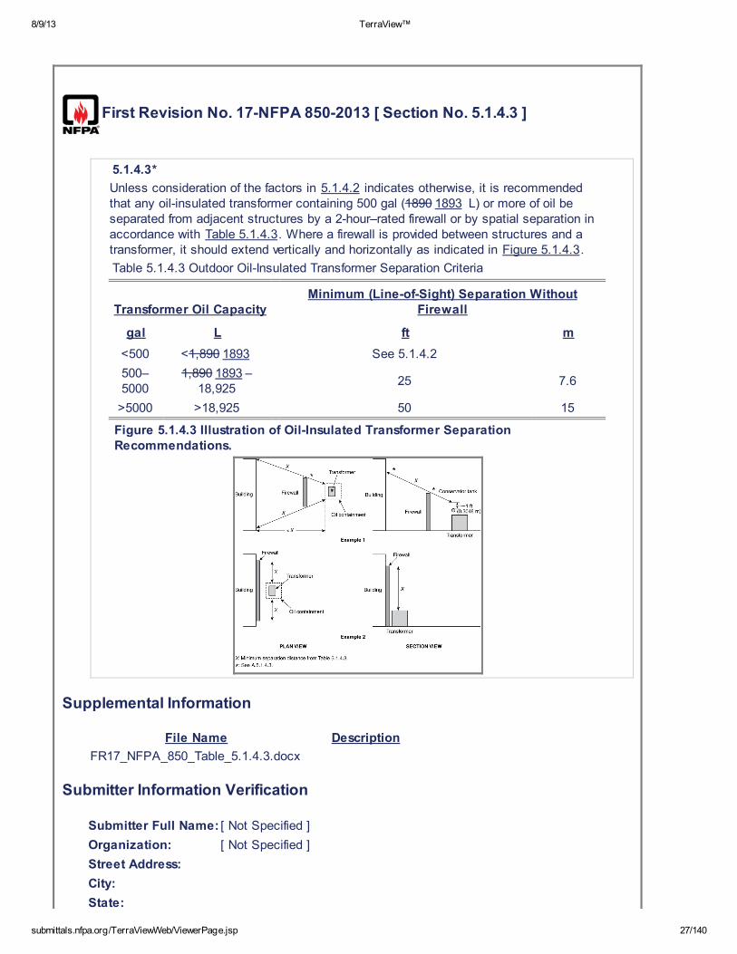
Unless consideration of the factors in 5.1.4.2 indicates otherwise, it is recommendedthat any oil-insulated transformer containing 500 gal (1890 1893 L) or more of oil beseparated from adjacent structures by a 2-hour–rated firewall or by spatial separation inaccordance with Table 5.1.4.3. Where a firewall is provided between structures and atransformer, it should extend vertically and horizontally as indicated in Figure 5.1.4.3.
Table 5.1.4.3 Outdoor Oil-Insulated Transformer Separation Criteria
Transformer Oil CapacityMinimum (Line-of-Sight) Separation Without
Firewall
gal L ft m
<500 <1,890 1893 See 5.1.4.2
500–5000
1,890 1893 –18,925
25 7.6
>5000 >18,925 50 15
Figure 5.1.4.3 Illustration of Oil-Insulated Transformer SeparationRecommendations.
Supplemental Information
File Name Description
FR17_NFPA_850_Table_5.1.4.3.docx
Submitter Information Verification
Submitter Full Name: [ Not Specified ]
Organization: [ Not Specified ]
Street Address:
City:
State:

8/9/13 TerraView™
submittals.nfpa.org/TerraViewWeb/ViewerPage.jsp 28/140
Zip:
Submittal Date: Tue May 21 14:25:52 EDT 2013
Committee Statement
CommitteeStatement:
Recommended practice criteria incorporated from NFPA 851. Reference in the tablehas been updated to call out the section that references transformers of less than500 gallons.
ResponseMessage:
8/9/13 TerraView™
submittals.nfpa.org/TerraViewWeb/ViewerPage.jsp 29/140
First Revision No. 18-NFPA 850-2013 [ Section No. 5.1.4.4 ]
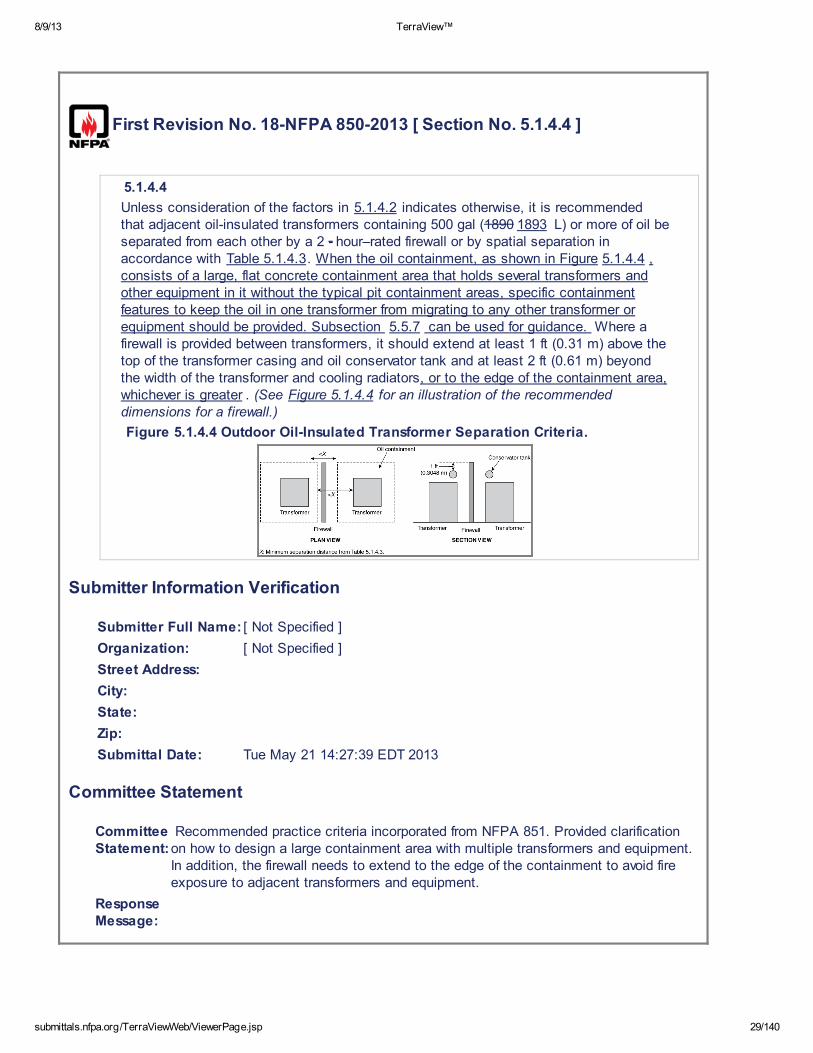
5.1.4.4
Unless consideration of the factors in 5.1.4.2 indicates otherwise, it is recommendedthat adjacent oil-insulated transformers containing 500 gal (1890 1893 L) or more of oil beseparated from each other by a 2 - hour–rated firewall or by spatial separation inaccordance with Table 5.1.4.3. When the oil containment, as shown in Figure 5.1.4.4 ,consists of a large, flat concrete containment area that holds several transformers andother equipment in it without the typical pit containment areas, specific containmentfeatures to keep the oil in one transformer from migrating to any other transformer orequipment should be provided. Subsection 5.5.7 can be used for guidance. Where afirewall is provided between transformers, it should extend at least 1 ft (0.31 m) above thetop of the transformer casing and oil conservator tank and at least 2 ft (0.61 m) beyondthe width of the transformer and cooling radiators, or to the edge of the containment area,whichever is greater . (See Figure 5.1.4.4 for an illustration of the recommendeddimensions for a firewall.)
Figure 5.1.4.4 Outdoor Oil-Insulated Transformer Separation Criteria.
Submitter Information Verification
Submitter Full Name: [ Not Specified ]
Organization: [ Not Specified ]
Street Address:
City:
State:
Zip:
Submittal Date: Tue May 21 14:27:39 EDT 2013
Committee Statement
CommitteeStatement:
Recommended practice criteria incorporated from NFPA 851. Provided clarificationon how to design a large containment area with multiple transformers and equipment.In addition, the firewall needs to extend to the edge of the containment to avoid fireexposure to adjacent transformers and equipment.
ResponseMessage:
8/9/13 TerraView™
submittals.nfpa.org/TerraViewWeb/ViewerPage.jsp 30/140
First Revision No. 19-NFPA 850-2013 [ Section No. 5.1.4.6 ]
5.1.4.6
For transformers with less than 500 gal (1890 1893 L) of oil and where a firewall is notprovided, the edge of the postulated oil spill (i.e., containment basin, if provided) shouldbe separated by a minimum of 5 ft (1.5 m) from the exposed structure to prevent directflame impingement on the structure.
Submitter Information Verification
Submitter Full Name: [ Not Specified ]
Organization: [ Not Specified ]
Street Address:
City:
State:
Zip:
Submittal Date: Tue May 21 14:28:30 EDT 2013
Committee Statement
Committee Statement: Recommended practice criteria incorporated from NFPA 851.
Response Message:
8/9/13 TerraView™
submittals.nfpa.org/TerraViewWeb/ViewerPage.jsp 31/140
First Revision No. 32-NFPA 850-2013 [ New Section after 5.1.5.4 ]
5.1.6 General Substation Arrangement.
Submitter Information Verification
Submitter Full Name: [ Not Specified ]
Organization: [ Not Specified ]
Street Address:
City:
State:
Zip:
Submittal Date: Wed May 22 09:05:45 EDT 2013
Committee Statement
CommitteeStatement:
This section will contain the general arrangement of transformers and associatedelectrical equipment as it pertains to the electric generating facility switch yard.
ResponseMessage:
8/9/13 TerraView™
submittals.nfpa.org/TerraViewWeb/ViewerPage.jsp 32/140
First Revision No. 20-NFPA 850-2013 [ Section No. 5.2.2 ]
5.2.2*
Structures should be classified as follows, as defined in NFPA 101, Life Safety Code:
(1) General areas should be considered as special purpose industrial occupancies.
(2) Open structures and underground structures (e.g., tunnels) should be considered asoccupancies in special structures. Temporary occupancies and means of egressinside the structures and piers of large "bulb" hydroelectric units should beevaluated based on occupancies in special structures.
(3) General office structures should be considered as business occupancies.
(4) Warehouses should be considered as storage occupancies.
(5) Coal preparation and handling facilities (e.g., enclosed crusher houses, transferhouses, and conveyors) should be considered special-purpose industrialoccupancies.
(6) Scrubber buildings should be considered as special- purpose industrialoccupancies.
Submitter Information Verification
Submitter Full Name: [ Not Specified ]
Organization: [ Not Specified ]
Street Address:
City:
State:
Zip:
Submittal Date: Tue May 21 14:33:14 EDT 2013
Committee Statement
Committee Statement: Recommended practice criteria incorporated from NFPA 851.
Response Message:

8/9/13 TerraView™
submittals.nfpa.org/TerraViewWeb/ViewerPage.jsp 33/140
First Revision No. 33-NFPA 850-2013 [ New Section after 5.2.3 ]
Submitter Information Verification
Submitter Full Name: [ Not Specified ]
Organization: [ Not Specified ]
Street Address:
City:
State:
Zip:
Submittal Date: Wed May 22 09:17:06 EDT 2013
Committee Statement
CommitteeStatement:
Emergency plans are developed for normal operating conditions. This newrecommendation takes into account the increased occupancy load associated withan outage.
ResponseMessage:
8/9/13 TerraView™
submittals.nfpa.org/TerraViewWeb/ViewerPage.jsp 34/140
First Revision No. 21-NFPA 850-2013 [ Section No. 5.3.1 ]
5.3.1
Construction materials being considered for electric generating plants and high-voltagedirect current converter stations should be selected based on the Fire Protection DesignBasis Document and on consideration of the following NFPA standards:
(1) NFPA 220, Standard on Types of Building Construction
NFPA 251 , Standard Methods of Tests of Fire Resistance of BuildingConstruction and Materials
(2) ASTM E 119 or ANSI/UL 263, Standard Test Methods for Fire Tests of BuildingConstruction and Materials
(3) NFPA 253, Standard Method of Test for Critical Radiant Flux of Floor CoveringSystems Using a Radiant Heat Energy Source
(4) NFPA 259, Standard Test Method for Potential Heat of Building Materials
(5) ASTM E 84, Standard Test Method for Surface Burning Characteristics of BuildingMaterials , or ANSI/UL 723, Test for Surface Burning Characteristics of BuildingMaterials
Submitter Information Verification
Submitter Full Name: [ Not Specified ]
Organization: [ Not Specified ]
Street Address:
City:
State:
Zip:
Submittal Date: Tue May 21 14:41:57 EDT 2013
Committee Statement
CommitteeStatement:
Recommended practice criteria incorporated from NFPA 851. ASTM E 119 andUL 263 has been added as a replacement to NFPA 251.
ResponseMessage:
8/9/13 TerraView™
submittals.nfpa.org/TerraViewWeb/ViewerPage.jsp 35/140
First Revision No. 34-NFPA 850-2013 [ Section No. 5.3.2 ]
5.3.2
Construction materials used in the boiler, engine, or turbine-generator buildings or otherbuildings critical to power generation or conversion should meet the definition ofnoncombustible or limited combustible, except for the following:
(1) Roof coverings, which should be as outlined in 5.3.4
(2) Limited use of translucent reinforced plastic panels as allowed by the FireProtection Design Basis Document
Submitter Information Verification
Submitter Full Name: [ Not Specified ]
Organization: [ Not Specified ]
Street Address:
City:
State:
Zip:
Submittal Date: Wed May 22 09:24:53 EDT 2013
Committee Statement
Committee Statement: Editorial
Response Message:
8/9/13 TerraView™
submittals.nfpa.org/TerraViewWeb/ViewerPage.jsp 36/140
First Revision No. 78-NFPA 850-2013 [ Section No. 5.4.1.3.2 ]
5.4.1.3.2*
Separate smoke management or ventilation systems are preferred; however, smokeventing can be integrated into normal ventilation systems using automatic or manuallypositioned dampers and motor speed control. (See NFPA 90A, Standard for theInstallation of Air-Conditioning and Ventilating Systems; NFPA 92A 92 , Standard forSmoke-Control Systems; Utilizing Barriers and Pressure Differences and NFPA 204,Standard for Smoke and Heat Venting .) Smoke venting also is permitted to beaccomplished through the use of portable smoke ejectors. A smoke managementsystem should be utilized to mitigate the effects of smoke and heat during the earlystages of a fire.
Submitter Information Verification
Submitter Full Name: [ Not Specified ]
Organization: [ Not Specified ]
Street Address:
City:
State:
Zip:
Submittal Date: Wed May 22 17:39:51 EDT 2013
Committee Statement
Committee Statement: Revised reference as NFPA 92A has been withdrawn.
Response Message:
8/9/13 TerraView™
submittals.nfpa.org/TerraViewWeb/ViewerPage.jsp 37/140
First Revision No. 35-NFPA 850-2013 [ Section No. 6.2.2 [Excluding any
Sub-Sections] ]
At least one reliable water supply should be provided. The Fire Protection Design BasisDocument should identify the need for multiple supply sources. Factors to considershould include the following:
(1) Reliability of source
(2) Capacity of source
(3) Reliance on water-based fire protection systems
(4) Availability of alternate and backup sources
(5) Consequences of a loss, in terms of property and generation
Submitter Information Verification
Submitter Full Name: [ Not Specified ]
Organization: [ Not Specified ]
Street Address:
City:
State:
Zip:
Submittal Date: Wed May 22 09:27:24 EDT 2013
Committee Statement
CommitteeStatement:
Clarifies that one water supply can be a reliable source for the fireprotection system(s).
ResponseMessage:

8/9/13 TerraView™
submittals.nfpa.org/TerraViewWeb/ViewerPage.jsp 38/140
First Revision No. 38-NFPA 850-2013 [ Section No. 6.2.2.1 ]
6.2.2.1*
Potential sources to be considered can include tanks, ponds, rivers, municipal supplies,and cooling tower basins.
Submitter Information Verification
Submitter Full Name: [ Not Specified ]
Organization: [ Not Specified ]
Street Address:
City:
State:
Zip:
Submittal Date: Wed May 22 09:54:42 EDT 2013
Committee Statement
Committee Statement: Annex material incorporated from NFPA 851.
Response Message:
8/9/13 TerraView™
submittals.nfpa.org/TerraViewWeb/ViewerPage.jsp 39/140
First Revision No. 40-NFPA 850-2013 [ New Section after 6.2.3 ]
6.2.3.1
Global FR-40 Hide Deleted
If a single water supply is utilized, two independent connections should be provided. If asituation can arise in which the primary water supply can become unavailable (e.g.,dewatering of penstocks), an auxiliary supply should be provided. Each supply shouldbe capable of meeting the recommendations in 6.2.2 .
Submitter Information Verification
Submitter Full Name: [ Not Specified ]
Organization: [ Not Specified ]
Street Address:
City:
State:
Zip:
Submittal Date: Wed May 22 09:59:36 EDT 2013
Committee Statement
Committee Statement: Incorporated recommendation from NFPA 851.
Response Message:
8/9/13 TerraView™
submittals.nfpa.org/TerraViewWeb/ViewerPage.jsp 40/140
First Revision No. 39-NFPA 850-2013 [ Section No. 6.2.3 ]
6.2.3
Each water supply should be connected to the station supply main or yard main byseparate connections arranged and valve controlled to minimize the possibility of multiplesupplies being impaired simultaneously.
6.2.3.1
Global FR-40 Hide Deleted
If a single water supply is utilized, two independent connections should be provided. If asituation can arise in which the primary water supply can become unavailable (e.g.,dewatering of penstocks), an auxiliary supply should be provided. Each supply shouldbe capable of meeting the recommendations in 6.2.2 .
Submitter Information Verification
Submitter Full Name: [ Not Specified ]
Organization: [ Not Specified ]
Street Address:
City:
State:
Zip:
Submittal Date: Wed May 22 09:55:30 EDT 2013
Committee Statement
Committee Statement: Incorporated recommendation from NFPA 851.
Response Message:
8/9/13 TerraView™
submittals.nfpa.org/TerraViewWeb/ViewerPage.jsp 41/140
First Revision No. 22-NFPA 850-2013 [ Section No. 6.2.5.2 ]
6.2.5.2
Fire pumps should be automatic starting with manual shutdown, except as allowed inNFPA 20, Standard for the Installation of Stationary Pumps for Fire Protection. Themanual shutdown should be at the pump controllers only. (See NFPA 20 .)
Submitter Information Verification
Submitter Full Name: [ Not Specified ]
Organization: [ Not Specified ]
Street Address:
City:
State:
Zip:
Submittal Date: Tue May 21 15:45:46 EDT 2013
Committee Statement
Committee Statement: Recommended practice criteria incorporated from NFPA 851.
Response Message:

8/9/13 TerraView™
submittals.nfpa.org/TerraViewWeb/ViewerPage.jsp 42/140
First Revision No. 105-NFPA 850-2013 [ Section No. 6.3 ]
6.3 Valve Supervision.
All fire protection water supply and system control valves should be under a periodicinspection program (see Chapter 16 17 ) and should be supervised by one of thefollowing methods:
(1) Electrical supervision with audible and visual signals in the main control room oranother constantly attended location.
(2) Locking valves open. Keys should be made available only to authorized personnel.
(3) Sealing valves open. This option should be followed only where valves are withinfenced enclosures under the control of the property owners.
Submitter Information Verification
Submitter Full Name: [ Not Specified ]
Organization: [ Not Specified ]
Street Address:
City:
State:
Zip:
Submittal Date: Mon Jun 03 10:41:41 EDT 2013
Committee Statement
Committee Statement: Editorial correction with the edition of new chapter 14.
Response Message:
First Revision No. 41-NFPA 850-2013 [ Section No. 6.4 ]
6.4 Supply Mains, Yard Mains, Hydrants, and Building Standpipes.
6.4.1 Supply Mains, Yard Mains, and Hydrants.
6.4.1.1
Supply mains, y Y ard mains, and outdoor fire hydrants should be installed on the plantsite. (See NFPA 24, Standard for the Installation of Private Fire Service Mains and TheirAppurtenances.) Hydrant spacing in main plant areas should be a maximum of 300 ft(91.4 m). Hydrant spacing in remote areas such as long-term coal storage should be amaximum of 500 ft (152.4 m).
8/9/13 TerraView™
submittals.nfpa.org/TerraViewWeb/ViewerPage.jsp 43/140
6.4.1.2
Remotely located plant-related facilities should be reviewed on an individual basis todetermine the need for fire protection. If excessively long extensions of underground firemains are necessary for fire protection at these locations, it can be permitted to supplythis need from an available service main in the immediate area. Where common supplypiping is provided for service water and fire protection water supply, it should be sized toaccommodate both service water and fire protection demands.
6.4.1.3
The supply mains should be looped around the main power block and should be ofsufficient size to supply the flow requirements determined by 6.2.1 to any point in theyard loop considering the most direct path to be out of service. Pipe sizes should bedesigned to encompass any anticipated expansion and future water demands.
6.4.1.4
Indicator control valves should be installed to provide adequate sectional control of the firemain loop to minimize plant protection impairments.
6.4.1.5
Each hydrant should be equipped with a separate shutoff valve located on the branchconnection to the supply main.
6.4.1.6
Interior fire protection loops are considered an extension of the yard main and should beprovided with at least two valved connections to the yard main with appropriate sectionalcontrol valves on the interior loop.
6.4.1.7
Global FR-23 Hide Deleted
It might be necessary for the fire department to draft from a body of water adjacent tothe plant. However, the terrain and elevation above the water supply can make it difficultfor drafting. Consideration should be given to installing a dry hydrant with adequate fireapparatus access.
6.4.2 Standpipe and Hose Systems.
6.4.2.1
Standpipe and hose systems should be installed in buildings and structures wheredeemed necessary by the Fire Protection Design Basis. (See NFPA 14 , Standard forthe Installation of Standpipe and Hose Systems .) The standpipe and hose system isan extension of the yard fire main and hydrant system. The hose stations should becapable of delivering the hose stream demand for the various hazards in buildings.
6.4.2.2
Fire main connections for standpipes should be arranged so that a fire main break canbe isolated without interrupting service simultaneously to both fixed protection and hoseconnections protecting the same hazard or area. Choice of Class I, Class II, or Class IIIsystems should be determined by a Fire Protection Design Basis. (See NFPA 14 ,Standard for the Installation of Standpipe and Hose Systems .)
6.4.2.3
The standpipe piping should be capable of providing minimum volume and pressure forthe highest hose stations.
6.4.2.4
Due to the open arrangement of these plants, the locations of hose stations should takeinto account safe egress for personnel operating hose lines.
6.4.3 Hose Nozzles.
Spray nozzles having shutoff capability and listed for use on electrical equipment shouldbe provided on hoses located in areas near energized electrical equipment.

8/9/13 TerraView™
submittals.nfpa.org/TerraViewWeb/ViewerPage.jsp 44/140
6.4.4 Hose Threads.
Hose threads on hydrants and standpipe systems should be compatible with fire hoseused by the responding fire departments.
Submitter Information Verification
Submitter Full Name: [ Not Specified ]
Organization: [ Not Specified ]
Street Address:
City:
State:
Zip:
Submittal Date: Wed May 22 10:01:43 EDT 2013
Committee Statement
Committee Statement: Incorporated recommendation from NFPA 851.
Response Message:
8/9/13 TerraView™
submittals.nfpa.org/TerraViewWeb/ViewerPage.jsp 45/140
First Revision No. 23-NFPA 850-2013 [ New Section after 6.4.1.6 ]
6.4.1.7
Global FR-23 Hide Deleted
It might be necessary for the fire department to draft from a body of water adjacent tothe plant. However, the terrain and elevation above the water supply can make it difficultfor drafting. Consideration should be given to installing a dry hydrant with adequate fireapparatus access.
Submitter Information Verification
Submitter Full Name: [ Not Specified ]
Organization: [ Not Specified ]
Street Address:
City:
State:
Zip:
Submittal Date: Tue May 21 15:53:48 EDT 2013
Committee Statement
CommitteeStatement:
Recommended practice criteria incorporated from NFPA 851 andeditorially revised.
Response Message:

8/9/13 TerraView™
submittals.nfpa.org/TerraViewWeb/ViewerPage.jsp 46/140
First Revision No. 24-NFPA 850-2013 [ Section No. 6.5 ]
6.5 Portable Fire Extinguishers.
Portable fire For first aid fire protection, suitable fire extinguishers should be provided.(See NFPA 10, Standard for Portable Fire Extinguishers.)
Submitter Information Verification
Submitter Full Name: [ Not Specified ]
Organization: [ Not Specified ]
Street Address:
City:
State:
Zip:
Submittal Date: Tue May 21 15:57:48 EDT 2013
Committee Statement
Committee Statement: Recommended practice criteria incorporated from NFPA 851.
Response Message:
8/9/13 TerraView™
submittals.nfpa.org/TerraViewWeb/ViewerPage.jsp 47/140
First Revision No. 77-NFPA 850-2013 [ Section No. 6.6.1 ]
6.6.1
Fire suppression systems and equipment should be provided in all areas of the plant asidentified in Chapters 7 through 15 or as determined by the Fire Protection Design BasisDocument . Fixed suppression systems should be designed in accordance with thefollowing codes and standards unless specifically noted otherwise:
(1) NFPA 11, Standard for Low-, Medium-, and High-Expansion Foam
(2) NFPA 12, Standard on Carbon Dioxide Extinguishing Systems
(3) NFPA 13, Standard for the Installation of Sprink ler Systems
(4) NFPA 15, Standard for Water Spray Fixed Systems for Fire Protection
(5) NFPA 16, Standard for the Installation of Foam-Water Sprink ler and Foam-WaterSpray Systems
(6) NFPA 17, Standard for Dry Chemical Extinguishing Systems
(7) NFPA 750, Standard on Water Mist Fire Protection Systems
(8) NFPA 2001, Standard on Clean Agent Fire Extinguishing Systems
(9) NFPA 2010, Standard for Aerosol Fire Extinguishing Systems
Submitter Information Verification
Submitter Full Name: [ Not Specified ]
Organization: [ Not Specified ]
Street Address:
City:
State:
Zip:
Submittal Date: Wed May 22 17:33:13 EDT 2013
Committee Statement
CommitteeStatement:
Aerosol Extinguishing systems are suitable for some suitable applications coveredby this document, but there is no reference to allow use of the technology.
ResponseMessage:
Public Input No. 12-NFPA 850-2012 [Section No. 6.6.1]
8/9/13 TerraView™
submittals.nfpa.org/TerraViewWeb/ViewerPage.jsp 48/140
First Revision No. 25-NFPA 850-2013 [ Section No. 6.6.2 ]
6.6.2
The selection of an extinguishing agent or a combination of extinguishing agents shouldbe based on the following:
(1) The type of hazard
(2) The effect of agent discharge on equipment
(3) The health hazards
Personnel hazards created by the discharge of CO 2 should be considered in the
design of the system. The design should take into account the immediate release ofCO 2 into the protected area and the possibility of CO 2 leakage, migration, and
settling into adjacent areas and lower elevations of the plant. See NFPA 12, Standardon Carbon Dioxide Extinguishing Systems , for hazards to personnel. At a minimum, ifCO 2 systems are provided, they should be provided with an odorizer for alerting
personnel, and breathing apparatus should be provided for operators in areas that cannotbe abandoned.
Submitter Information Verification
Submitter Full Name: [ Not Specified ]
Organization: [ Not Specified ]
Street Address:
City:
State:
Zip:
Submittal Date: Tue May 21 15:59:57 EDT 2013
Committee Statement
Committee Statement: Recommended practice criteria incorporated from NFPA 851.
Response Message:
8/9/13 TerraView™
submittals.nfpa.org/TerraViewWeb/ViewerPage.jsp 49/140
First Revision No. 26-NFPA 850-2013 [ Section No. 6.7.3 ]
6.7.3
The fire-signaling system or plant communication system should provide the following:
(1) Manual fire alarm devices (e.g., pull boxes or page party stations) installed in alloccupied buildings. Manual fire alarm devices should be installed for remote yardhazards as identified by the Fire Protection Design Basis Document .
(2)
(3) Two-way communications for the plant emergency organization during emergencyoperations.
(4) Means to notify the public fire department.
Submitter Information Verification
Submitter Full Name: [ Not Specified ]
Organization: [ Not Specified ]
Street Address:
City:
State:
Zip:
Submittal Date: Tue May 21 16:19:30 EDT 2013
Committee Statement
CommitteeStatement:
The recommendation from NFPA 851, section 6.8.1.2 has been editorially revisedfor clarity and incorporated as annex language into NFPA 850.
ResponseMessage:
* Plant-wide audible fire alarm or voice communication systems, or both, forpurposes of personnel evacuation and alerting of plant emergency organization. Theplant public address system, if provided, should be available on a priority basis.

8/9/13 TerraView™
submittals.nfpa.org/TerraViewWeb/ViewerPage.jsp 50/140
First Revision No. 42-NFPA 850-2013 [ Section No. 7.2.1 ]
7.2.1*
The storage and associated piping systems for gases in the gaseous or liquefied statesshould comply with NFPA 54, National Fuel Gas Code; NFPA 55, Compressed Gasesand Cryogenic Fluids Code ; NFPA 56 , Fire and Explosion Prevention During Cleaningand Purging of Flammable Gas Piping System , Compressed Gases and CryogenicFluids Code ; NFPA 58, Liquefied Petroleum Gas Code; and ASME B31.1, PowerPiping.
Submitter Information Verification
Submitter Full Name: [ Not Specified ]
Organization: [ Not Specified ]
Street Address:
City:
State:
Zip:
Submittal Date: Wed May 22 10:20:54 EDT 2013
Committee Statement
Committee Statement: This change is intended to incorporate the TIA 10-2.
Response Message:

8/9/13 TerraView™
submittals.nfpa.org/TerraViewWeb/ViewerPage.jsp 51/140
First Revision No. 55-NFPA 850-2013 [ Section No. 7.2.2 ]
7.2.2
The plant’s main and igniter natural fuel gas shutoff valve should be located near anexterior wall in a remote area and accessible under emergency conditions . The valveshould be provided with both manual and automatic closing capabilities locally, andremote closing capability from the control room. The valve should be arranged to failclosed on the loss of power or pneumatic control.
Submitter Information Verification
Submitter Full Name: [ Not Specified ]
Organization: [ Not Specified ]
Street Address:
City:
State:
Zip:
Submittal Date: Wed May 22 12:39:40 EDT 2013
Committee Statement
Committee Statement: Revised TIA 10-2 language to address where plants are not indoors.
Response Message:

8/9/13 TerraView™
submittals.nfpa.org/TerraViewWeb/ViewerPage.jsp 52/140
First Revision No. 56-NFPA 850-2013 [ New Section after 7.2.3 ]
Submitter Information Verification
Submitter Full Name: [ Not Specified ]
Organization: [ Not Specified ]
Street Address:
City:
State:
Zip:
Submittal Date: Wed May 22 12:46:33 EDT 2013
Committee Statement
Committee Statement: Incorporated from TIA 10-2
Response Message:
First Revision No. 58-NFPA 850-2013 [ New Section after 7.2.3 ]
Submitter Information Verification
Submitter Full Name: [ Not Specified ]
Organization: [ Not Specified ]
Street Address:
City:
State:
Zip:
Submittal Date: Wed May 22 12:51:06 EDT 2013
Committee Statement
Committee Statement: Incorporated from TIA 10-2
Response Message:
8/9/13 TerraView™
submittals.nfpa.org/TerraViewWeb/ViewerPage.jsp 53/140
First Revision No. 107-NFPA 850-2013 [ Section No. 7.4.1.3 ]
7.4.1.3
Where coal storage barns or domes are used to enclose storage piles, the fire detection,fire protection, fire alarm, dust collection, dust suppression, explosion venting, andhousekeeping recommendations contained herein for coal handling areas and structuresshould be considered. The plant-specific features provided for the coal barn/dome shouldbe as determined during the Fire Protection Design Process Document . (See Chapter4.)
Submitter Information Verification
Submitter Full Name: [ Not Specified ]
Organization: [ Not Specified ]
Street Address:
City:
State:
Zip:
Submittal Date: Mon Jun 03 11:33:24 EDT 2013
Committee Statement
CommitteeStatement:
Due to the potential for elements required for a dust explosion to exist within a coalstorage barn or dome, explosion venting should be considered per NFPA 654.
ResponseMessage:
8/9/13 TerraView™
submittals.nfpa.org/TerraViewWeb/ViewerPage.jsp 54/140
First Revision No. 108-NFPA 850-2013 [ Section No. 7.4.2.5 ]
7.4.2.5
Once spontaneous heating develops to the fire stage, it becomes very difficult toextinguish the fire short of emptying the bin, bunker, or silo. Therefore, provisions foremptying the bin, bunker, or silo should be provided. This unloading process might takethe form of conveyors discharging to a stacking out pile. Another method would be touse flanged openings for removing the coal if adequate planning and necessaryequipment have been provided. Removing hot or burning coal can lead to a dust explosionif a dust cloud develops. Proper pre-planning preplanning should be developed to preventa dust cloud, such as covering the coal with a blanket of high-expansion foam, watermist, water spray with fire-fighting additives, dust suppression, or dust collection.
Submitter Information Verification
Submitter Full Name: [ Not Specified ]
Organization: [ Not Specified ]
Street Address:
City:
State:
Zip:
Submittal Date: Mon Jun 03 11:35:01 EDT 2013
Committee Statement
CommitteeStatement:
For consistency within the document, included bin, bunker, or silo so that the readerconsiders the potential hazards and methods to mitigate the hazards regardless ofthe shape or common name of the temporary storage container.
ResponseMessage:
8/9/13 TerraView™
submittals.nfpa.org/TerraViewWeb/ViewerPage.jsp 55/140
First Revision No. 44-NFPA 850-2013 [ Section No. 7.4.2.6 [Excluding
any Sub-Sections] ]
If fire occurs in a silo, it is necessary to initiate manual actions for suppression andextinguishment. The following fire-fighting strategies have been successfully employed(depending on the specific circumstances and type of coal used):
(1) Use of fire-fighting additives such as Class A foams, penetrants, or micelle-encapsulating wetting agents and water additives
(2) Injection of inert gas
(3) Emptying the silo through the feeder pipe to a safe location (inside or outside thepowerhouse) and trucking away the debris
Submitter Information Verification
Submitter Full Name: [ Not Specified ]
Organization: [ Not Specified ]
Street Address:
City:
State:
Zip:
Submittal Date: Wed May 22 10:50:34 EDT 2013
Committee Statement
CommitteeStatement:
The current FPRF project to evaluate water additives for Class A and Class B firesincludes NFPA 18 Wetting Agents and NFPA 18A Water Additives. “Micelle-encapsulating” agents are a subset of these groups. The change was made to begenerally refer to all agents being evaluated by the FPRF project.
ResponseMessage:
8/9/13 TerraView™
submittals.nfpa.org/TerraViewWeb/ViewerPage.jsp 56/140
First Revision No. 109-NFPA 850-2013 [ Section No. 7.4.2.6.1 ]
7.4.2.6.1
The following fire-fighting strategies should be taken into consideration:
(1) Water has been successfully used successfully to control bunker and silo fires.However, the possibility of an explosion exists under certain circumstances if thewater reaches the coal in a hot spot. Therefore, water is not a recommended fire-fighting strategy for these types of fire events. The amount of water delivered to asilo in a stream can create structural support problems. However, use of fire-fightingadditives with water can be highly effective for coal fires, especially Powder RiverBasin (PRB) sub-bituminous coal fires. This use of fire-fighting additives typicallyresults in significantly less water being delivered into the silo due to the enhancedfire suppression properties of the agent and subsequent shorter delivery period.
(2) Steam-smothering has also been used to control bunker and silo fires on marinevessels. All openings need to be sealed prior to the introduction of steam, which israrely possible at electric generating plants due to the relatively porous nature of theequipment. The use of steam introduces high temperature and moisture that couldincrease the possibility of spontaneous combustion; therefore, this strategy is notrecommended.
(3) Locating silo hot spots and extinguishing them before the coal leaves the silo is anaccepted practice. The coal hot spots are detected and extinguished. If, as the coaldrops down through the silo, additional hot spots are detected, coal flow should bestopped and the hot spots extinguished. If the hot spots are exposed during thelowering of the coal, potential for dust explosions is increased.
Submitter Information Verification
Submitter Full Name: [ Not Specified ]
Organization: [ Not Specified ]
Street Address:
City:
State:
Zip:
Submittal Date: Mon Jun 03 11:36:51 EDT 2013
Committee Statement
CommitteeStatement:
PRB coal is commonly a reference to a geography area where sub-bituminous coalis mined. The intent is to focus on sub bituminous coal regardless of where it ismined but rather on the characteristics of this particular rank of coal.
ResponseMessage:

8/9/13 TerraView™
submittals.nfpa.org/TerraViewWeb/ViewerPage.jsp 57/140
First Revision No. 46-NFPA 850-2013 [ New Section after 7.4.2.8 ]
7.4.2.9
It might not be practical to install explosion vents on a coal bin, bunker, and silo. Typicalsilo designs do not have sufficient area above the coal level for properly designedexplosion vents. Vents would present an exposure hazard to any personnel in adjacentareas (see NFPA 654, Standard for the Prevention of Fire and Dust Explosions fromthe Manufacturing, Processing, and Handling of Combustible Particulate Solids) . Ifexplosion vents are considered, they should be designed in accordance with NFPA 68,Standard on Explosion Protection by Deflagration Venting .
Submitter Information Verification
Submitter Full Name: [ Not Specified ]
Organization: [ Not Specified ]
Street Address:
City:
State:
Zip:
Submittal Date: Wed May 22 11:04:59 EDT 2013
Committee Statement
CommitteeStatement:
This provides guidance for the user in a recommended reference to NFPA654.
Response Message:
First Revision No. 110-NFPA 850-2013 [ Section No. 7.4.3.4 ]

8/9/13 TerraView™
submittals.nfpa.org/TerraViewWeb/ViewerPage.jsp 58/140
7.4.3.4
Dust collectors should be located outside. For dust collection systems provided forhandling combustible dusts, see NFPA 654, Standard for the Prevention of Fire and DustExplosions from the Manufacturing, Processing, and Handling of Combustible ParticulateSolids. Other recommendations for reducing the probability of explosion and fire from coaldust are as follows:
(1) Fans for dust collectors should be installed downstream of the collectors so thatthey handle only clean air.
(2) For dust collectors vented to the outside, see NFPA 68, Standard on ExplosionProtection by Deflagration Venting. Explosion suppression systems are permittedto be provided for dust collection systems that cannot be safely vented to theoutside. (See NFPA 69, Standard on Explosion Prevention Systems.)
(3) Dust collection hoppers should be emptied prior to shutting down dust removalsystems to reduce the likelihood of collector fires originating from spontaneousheating in the dust hopper.
(4) Dust collectors should not discharge into inactive coal storage bins, bunkers, orsilos.
(5) High-level detection with an annunciator alarm should be provided for the dusthoppers.
(6) Monitoring and trending for carbon monoxide should be provided for dust collectorsto detect spontaneous combustion.
Submitter Information Verification
Submitter Full Name: [ Not Specified ]
Organization: [ Not Specified ]
Street Address:
City:
State:
Zip:
Submittal Date: Mon Jun 03 11:39:18 EDT 2013
Committee Statement
CommitteeStatement:
Dust discharged from dust collectors into inactive coal storage bins, bunkers, orsilos increase the risk for fire and explosions as it tends be remain for an extendedperiod of time, spontaneously combust,and due to its fine particle size likely tobecome suspended in air increasing risk for explosion or flash fire. Carbon monoxideis amongst the earliest known methods to detect a coal related fire and theimportance of trending to discover a potential developing concern soon rather thanlater so that actions can be taken to reduce severity.
ResponseMessage:

8/9/13 TerraView™
submittals.nfpa.org/TerraViewWeb/ViewerPage.jsp 59/140
First Revision No. 111-NFPA 850-2013 [ Section No. 7.4.6.1 ]
7.4.6.1
Automatic sprinkler or water spray fixed systems should be provided for coal handlingstructures that are critical to power generation and subject to accumulations of coal orcoal dust. Sprinkler Automatic sprinkler systems should be designed for a minimum of
0.25 gpm/ft2 (10.2 mm/min) density over a 2500 ft2 (232 m2) area. If water spray fixedsystems are used to protect structures, the same densities should be used.
Submitter Information Verification
Submitter Full Name: [ Not Specified ]
Organization: [ Not Specified ]
Street Address:
City:
State:
Zip:
Submittal Date: Mon Jun 03 11:46:30 EDT 2013
Committee Statement
Committee Statement: Editorial.
Response Message:
8/9/13 TerraView™
submittals.nfpa.org/TerraViewWeb/ViewerPage.jsp 60/140
First Revision No. 113-NFPA 850-2013 [ Section No. 7.4.6.2 [Excluding
any Sub-Sections] ]
Automatic sprinkler or water spray or sprinkler fixed systems should be provided for coalconveyors that are critical to continuous power generation. System coverage shouldinclude transfer points (tail dust hoods and head chutes). Sprinklers should be designed
for a minimum of 0.25 gpm/ft2 (10.2 mm/min) density over 2000 ft2 (186 m2) of enclosed
area or the most remote 100 linear ft (30 m) of conveyor structure up to 2000 ft2 (186 m2).For water spray design criteria, see NFPA 15, Standard for Water Spray Fixed Systemsfor Fire Protection. Water spray systems should be considered for enclosed conveyorsthat are inclined because of the greater potential for rapid fire spread .
Submitter Information Verification
Submitter Full Name: [ Not Specified ]
Organization: [ Not Specified ]
Street Address:
City:
State:
Zip:
Submittal Date: Mon Jun 03 13:36:44 EDT 2013
Committee Statement
Committee Statement: Editorial.
Response Message:

8/9/13 TerraView™
submittals.nfpa.org/TerraViewWeb/ViewerPage.jsp 61/140
First Revision No. 115-NFPA 850-2013 [ Section No. 7.4.6.5.1 ]
7.4.6.5.1
Sprinklers for bag-type dust collectors should be designed for ordinary hazard systems.
Sprinkler and water spray systems should be designed for a density of 0.20 gpm/ft2 (8.1mm/min) over the projected plan area of the dust collector. Use of fire-fighting additivesshould be considered for PRB sub-bituminous coal dust collectors.
Submitter Information Verification
Submitter Full Name: [ Not Specified ]
Organization: [ Not Specified ]
Street Address:
City:
State:
Zip:
Submittal Date: Mon Jun 03 14:09:56 EDT 2013
Committee Statement
CommitteeStatement:
PRB coal is commonly a reference to a geography area where sub-bituminous coalis mined. The intent is to focus on sub bituminous coal regardless of where it ismined but rather on the characteristics of this particular rank of coal.
ResponseMessage:
8/9/13 TerraView™
submittals.nfpa.org/TerraViewWeb/ViewerPage.jsp 62/140
First Revision No. 60-NFPA 850-2013 [ New Section after 7.5.2.2 ]
7.5.2.3
Pulverizer explosion mitigation methods to consider include inerting and temperaturecontrol.
7.5.2.4
Personnel warning systems should be considered during pulverizer startup, shutdown,and trip.
Submitter Information Verification
Submitter Full Name: [ Not Specified ]
Organization: [ Not Specified ]
Street Address:
City:
State:
Zip:
Submittal Date: Wed May 22 13:35:19 EDT 2013
Committee Statement
CommitteeStatement:
For life safety, a better practice is to mitigate the risk of explosion during probabletimes when the fuel ratio (coal and air) transition through an explosive range. Inaddition to mitigation systems such as inerting, temperature control, explosionsuppression, is to warn personnel who may be in the area so that they evacuateduring this time,
ResponseMessage:
First Revision No. 47-NFPA 850-2013 [ New Section after 7.6.6 ]
7.6.7 Activated Carbon Injection Systems.
7.6.7.1 General.
Activated carbon injection (ACI) systems are used on some coal-fired plants to adsorbmercury from the flue gas. Powdered activated carbon (PAC) is stored in silos andpneumatically conveyed to the flue gas duct work and injected into the flue gas stream.Residual PAC (spent) is collected with fly ash in the baghouse ash hoppers.

8/9/13 TerraView™
submittals.nfpa.org/TerraViewWeb/ViewerPage.jsp 63/140
7.6.7.2 Types of Powdered Activated Carbon.
Powdered activated carbon (PAC) for use at power plants is typically a steam-activatedcarbon product. The feedstock varies by manufacturer, but steam-activated carbon is notsubject to spontaneous heating. Chemically activated carbon products are subject tospontaneous heating and are not typically used at power plants. The activation methodshould be identified and considered in the Fire Protection Design Basis Document. PACproducts might or might not be combustible or explosible, and testing is recommendedfor the PAC products specified for the plant-specific ACI system. If the product cannotbe identified and tested prior to the design of the ACI system, then the Fire ProtectionDesign Basis Document should consider a worst-case scenario.
7.6.7.3 Storage of Powdered Activated Carbon.
PAC is typically stored in outdoor silos filled pneumatically by tank truck or rail tankcar. Trucks connect to fill connections at grade, and PAC is transported into the top ofthe silos via a blower on the truck or at the rail car unloading station. In addition to fillpiping and instrumentation, there is typically a bin vent filter at the top of the silo (nottypically enclosed). The skirt area of the silo below the hopper might contain fluidizingair piping, PAC day bins, piping, instrumentation, etc. Depending on the PAC testresults, enclosed areas should be evaluated for the plant’s combustible dust program inaccordance with NFPA 654, Standard for the Prevention of Fire and Dust Explosionsfrom the Manufacturing, Processing, and Handling of Combustible Particulate Solids .
7.6.7.4 Effect of PAC on Fly Ash Properties.
Fly ash hoppers downstream of the PAC injection point will contain spent PAC in somepercentage. The percentage depends on operating conditions, whether or not the PAC isinjected downstream or upstream of an electrostatic precipitator, and whether or not theunit uses other inert materials in the process such as a dry sorbent. If the PAC isdetermined to be combustible and/or explosible (see 7.6.7.2 ) , then the fly ash/spentPAC mixture in the collection points (e.g., baghouse hoppers) should be evaluatedbased on the worst-case operating conditions. This could require testing to determine ifthe mixture is combustible or explosible. The results should be considered in the FireProtection Design Basis Document.
7.6.7.5 Fire Protection.

8/9/13 TerraView™
submittals.nfpa.org/TerraViewWeb/ViewerPage.jsp 64/140
Where fire detection is recommended by the Fire Protection Design Basis Document,carbon monoxide monitors should be located on the clean side of the silo bin vent filters.Upon receipt of an alarm, thermographic cameras should be used to confirm thepresense of a fire in the silo.
Where fire protection is recommended by the Fire Protection Design Basis Document,one of the following methods of protection should be provided:
(1) A fixed water-based (water, foam-water, water with wetting agents and/or wateradditives) system that is designed to protect a full silo. However, admitting waterinto a full PAC silo will create a sludge that is not likely to flow out of a drainconnection. The silo design should accommodate removal of this sludge after afire is suppressed. Structural design should accommodate the added weight ofthe water. The system could utilize a fixed water supply or be supplied viamanual connections located remote from the silos. The silo should be equippedwith access platforms for maintenance of nozzles.
(2) A fixed water-based (water, foam-water, water with wetting agents and/or wateradditives) system that is designed to wash down a nearly empty silo. In thiscase, the silo design should accommodate removal of the PAC prior to activationof the wash down system. The wash down nozzles could be minimized (e.g., atthe top only) to minimize the number of penetrations in the silo. This methodminimizes the amount of sludge created by putting water on the PAC.
(3) Low-pressure carbon dioxide (CO 2 ) can be used to inert the silo. This can be a
fixed system with a low-pressure CO 2 storage tank, vaporizer, and distribution
piping. The silo manufacturer should be consulted during design of the system toconfirm that the silo design pressure is high enough for a CO 2 discharge, and
to confirm how many nozzle locations are required to ensure that the CO 2 can
permeate the dense PAC in the silo. As an alternate to the fixed low-pressure CO 2 storage tank, the system could utilize a dry-header and fixed
vaporizer with connections for a CO 2 tank truck. The silo should be equipped
with access platforms for maintenance of nozzles.
(4) Other approved means.
Submitter Information Verification
Submitter Full Name: [ Not Specified ]
Organization: [ Not Specified ]
Street Address:
City:
State:
Zip:
Submittal Date: Wed May 22 11:20:52 EDT 2013
Committee Statement
CommitteeStatement:
ACI systems are increasingly common and recent testing of various PAC sampleshas determined that some products are combustible and explosible. Chapter 7 didnot address ACI or PAC in previous editions.
Response
8/9/13 TerraView™
submittals.nfpa.org/TerraViewWeb/ViewerPage.jsp 65/140
Message:
First Revision No. 48-NFPA 850-2013 [ New Section after 7.7.4.5 ]
7.7.4.6*
The use of a listed fire-resistant fluid as a turbine-generator lubricating oil (see 7.7.3.1 )could eliminate the need for fire protection beneath the operating floor, at lubricating oillines, lubricating oil reservoir, and turbine-generator bearings to mitigate the hazardposed solely by pool and three-dimensional fires involving lubrication oil.
Protection against pool and three-dimensional fires in accordance with 7.7.4.1 shouldbe installed if the hydrogen seal oil system does not use listed fire-resistant fluids.Generator bearings for seal oil systems not using listed fire-resistant fluids should beprotected in accordance with 7.7.4.2 . Stakeholders should be involved in thedecisionmaking process before eliminating fire protection for the turbine lubrication oilhazard.
Submitter Information Verification
Submitter Full Name: [ Not Specified ]
Organization: [ Not Specified ]
Street Address:
City:
State:
Zip:
Submittal Date: Wed May 22 11:37:38 EDT 2013
Committee Statement
CommitteeStatement:
Less flammable fluid use is addressed in other areas of the recommended practice,primarily for hydraulic fluids. Therefore, the use of less flammable fluids used in otherapplications may warrant the elimination of the fire protection if agreed by thestakeholders in the development of the fire protection design basis document.
ResponseMessage:

8/9/13 TerraView™
submittals.nfpa.org/TerraViewWeb/ViewerPage.jsp 66/140
First Revision No. 50-NFPA 850-2013 [ Section No. 7.8.1.3 ]
7.8.1.3
Automatic sprinkler protection or automatic water mist fire protection systems for thecomputer or telecommunications rooms should be considered in the Fire ProtectionDesign Basis Document . A preaction system can be used. In addition, total floodinggaseous fire extinguishing systems should be considered for areas beneath above andbelow raised floors that contain cables or for areas or enclosures containing equipmentthat is of high value or is critical to power generation. Individual equipment and cabinetprotection could be considered in lieu of total flooding systems.
Submitter Information Verification
Submitter Full Name: [ Not Specified ]
Organization: [ Not Specified ]
Street Address:
City:
State:
Zip:
Submittal Date: Wed May 22 11:53:55 EDT 2013
Committee Statement
CommitteeStatement:
This edit reflects the latest NFPA 2001 which does not allow clean agent protectionbelow the floor only. If clean agent protection is installed below the floor, 2001 nowrequires that protection also be installed above the floor.
ResponseMessage:
8/9/13 TerraView™
submittals.nfpa.org/TerraViewWeb/ViewerPage.jsp 67/140
First Revision No. 51-NFPA 850-2013 [ Section No. 7.8.5 ]
7.8.5* Battery Rooms.
Battery rooms should be provided with ventilation to limit the concentration of hydrogen to1 percent by volume. For further information refer to ANSI/IEEE 484, RecommendedPractice for Installation Design and Installation of Large Lead Storage Batteries forGenerating Stations and Substations.
Submitter Information Verification
Submitter Full Name: [ Not Specified ]
Organization: [ Not Specified ]
Street Address:
City:
State:
Zip:
Submittal Date: Wed May 22 11:59:35 EDT 2013
Committee Statement
Committee Statement: Explanatory material added to clarify our position relative to IEEE 484.
Response Message:
8/9/13 TerraView™
submittals.nfpa.org/TerraViewWeb/ViewerPage.jsp 68/140
First Revision No. 54-NFPA 850-2013 [ Section No. 7.9.1.2.1 ]
7.9.1.2.1
Emergency generators located within main plant structures should be protected byautomatic sprinkler, water spray, foam-water sprinkler, compressed air foam, or gaseous-type extinguishing systems. Sprinkler and water spray protection systems should be
designed for a 0.25 gpm/ft 2 (10.2 mm/min) density over the fire area. Compressed airfoam systems should be designed and installed in accordance with NFPA 11 37 ,Standard for Low-, Medium-, and High-Expansion Foam the Installation and Use ofStationary Combustion Engines and Gas Turbines , and their listing for the specifichazards and protection objectives specified in the listing .
Submitter Information Verification
Submitter Full Name: [ Not Specified ]
Organization: [ Not Specified ]
Street Address:
City:
State:
Zip:
Submittal Date: Wed May 22 12:07:23 EDT 2013
Committee Statement
CommitteeStatement:
NFPA 37 addresses stationary combustion engines an gas turbines, therefore7.9.1.2.1 has been revised to reference NFPA 37 for fire protection.
ResponseMessage:
8/9/13 TerraView™
submittals.nfpa.org/TerraViewWeb/ViewerPage.jsp 69/140
First Revision No. 53-NFPA 850-2013 [ Section No. 7.9.4 ]
7.9.4 Fire Pumps.
Rooms housing diesel-driven fire pumps should be protected by automatic sprinkler,water spray, foam-water sprinkler, or compressed air foam systems. If sprinkler andwater spray protection systems are provided for fire pump houses, they should be
designed for a density of 0.25 gpm/ft 2 (10.2 mm/min) over the fire area. Compressed airfoam systems should be designed and installed in accordance with NFPA 11 20 ,Standard for Low-, Medium-, and High-Expansion Foam Installation of Stationary Pumpsfor Fire Protection , and their listing for the specific hazards and protection objectivesspecified in the listing .
Submitter Information Verification
Submitter Full Name: [ Not Specified ]
Organization: [ Not Specified ]
Street Address:
City:
State:
Zip:
Submittal Date: Wed May 22 12:04:04 EDT 2013
Committee Statement
CommitteeStatement:
This change provides a reference to NFPA 20 and deletes the previous(lower) density
ResponseMessage:
8/9/13 TerraView™
submittals.nfpa.org/TerraViewWeb/ViewerPage.jsp 70/140
First Revision No. 102-NFPA 850-2013 [ New Section after 7.9.7 ]
7.9.8
The storage and piping systems of fuels in the gaseous or liquefied state should complywith NFPA 31, Standard for the Installation of Oil-Burning Equipment ; NFPA 54,National Fuel Gas Code ; NFPA 58, Liquefied Petroleum Gas Code ; and NFPA 85,Boiler and Combustion Systems Hazards Code , as applicable.
Submitter Information Verification
Submitter Full Name: [ Not Specified ]
Organization: [ Not Specified ]
Street Address:
City:
State:
Zip:
Submittal Date: Fri May 31 08:21:07 EDT 2013
Committee Statement
Committee Statement: Incorporated recommendation from NFPA 851.
Response Message:
8/9/13 TerraView™
submittals.nfpa.org/TerraViewWeb/ViewerPage.jsp 71/140
First Revision No. 88-NFPA 850-2013 [ Section No. 8.2 ]
8.2 Application of Chapters 4 through 7, 15, and 16.
The recommendations contained in Chapters 4 through 7, 16, and 17 can apply tocombustion turbine electric generating units. The Fire Protection Design Basis Documentwill determine which recommendations apply to any specific CT and ICE electricgenerating units. This determination is done by evaluating the specific hazards that existin the facility and evaluating the level of acceptable risk for the facility. For large CT unitsor combined cycle plants, it is expected that most of the recommendations will apply,whereas but for individual individually packaged CT and ICE units, many of therecommendations will not apply since the hazards described might not exist (e.g., smallunits might not have a cable spreading room or a warehouse).
Submitter Information Verification
Submitter Full Name: [ Not Specified ]
Organization: [ Not Specified ]
Street Address:
City:
State:
Zip:
Submittal Date: Thu May 30 11:35:55 EDT 2013
Committee Statement
CommitteeStatement:
Editorial. A new chapter 14 was added moving chapters 15 and 16 to 16and 17.
Response Message:
8/9/13 TerraView™
submittals.nfpa.org/TerraViewWeb/ViewerPage.jsp 72/140
First Revision No. 66-NFPA 850-2013 [ New Section after 8.5.4.7 ]
8.5.4.8 Fixed Aerosol Fire Extinguishing Systems.
Where provided, fixed aerosol fire extinguishing systems should be installed inaccordance with the requirements of NFPA 2010 , Standard for Fixed Aerosol FireExtinguishing Systems .
Submitter Information Verification
Submitter Full Name: [ Not Specified ]
Organization: [ Not Specified ]
Street Address:
City:
State:
Zip:
Submittal Date: Wed May 22 14:45:55 EDT 2013
Committee Statement
CommitteeStatement:
NFPA 2010 has been recognized as a new technology for providing fireprotection.
Response Message:

8/9/13 TerraView™
submittals.nfpa.org/TerraViewWeb/ViewerPage.jsp 73/140
First Revision No. 114-NFPA 850-2013 [ Section No. 9.2 ]
9.2 Application of Chapters 4 through 7, 15 16 , and 16 17 .
The recommendations contained in Chapters 4 through 7, 16, and 17 can apply toalternative fuel–fired electric generating station units. The Fire Protection Design BasisDocument will determine which recommendations apply to any specific alternative fuel–fired unit. This is done by evaluating the specific hazards that exist in the facility anddetermining the level of acceptable risk for the facility. It is expected that most of therecommendations will apply to all units, except as follows:
(1) Where size and specific design eliminate certain hazards (e.g., H2 seal oil units,
cable spreading rooms, or warehouses)
(2) Where the Fire Protection Design Basis Document indicates a single source ofwater (e.g., a single tank) is considered adequate and reliable
Submitter Information Verification
Submitter Full Name: [ Not Specified ]
Organization: [ Not Specified ]
Street Address:
City:
State:
Zip:
Submittal Date: Mon Jun 03 13:44:59 EDT 2013
Committee Statement
Committee Statement: Editorial.
Response Message:
8/9/13 TerraView™
submittals.nfpa.org/TerraViewWeb/ViewerPage.jsp 74/140
First Revision No. 70-NFPA 850-2013 [ Section No. 9.3.3.1 ]
9.3.3.1*
The tipping/receiving building should be provided with automatic sprinkler protection
throughout. Systems should be designed for a minimum of 0.25 gpm/ft2 (10.2 mm/min)
over the most remote 3000 ft2 (279 m2) (increase by 30 percent for dry pipe systems) of
floor area with the protection area per sprinkler not to exceed 130 ft2 (120 12 m2). High -temperature sprinklers [250°F to 300°F (121°C to 149°C)] should be used. If thetipping/receiving floor is to be used as the charging storage area, additional protectionshould be provided in accordance with 9.3.3.2.2 .
Submitter Information Verification
Submitter Full Name: [ Not Specified ]
Organization: [ Not Specified ]
Street Address:
City:
State:
Zip:
Submittal Date: Wed May 22 15:31:35 EDT 2013
Committee Statement
CommitteeStatement:
Sometimes the tripping/receiving floor is used as a charging storage area andtherefore additional protection is recommended.
ResponseMessage:
8/9/13 TerraView™
submittals.nfpa.org/TerraViewWeb/ViewerPage.jsp 75/140
First Revision No. 67-NFPA 850-2013 [ Section No. 9.6.3 ]
9.6.3 Prevention of Fires and Explosions in Scrap Rubber Tires.
(Reserved)
Submitter Information Verification
Submitter Full Name: [ Not Specified ]
Organization: [ Not Specified ]
Street Address:
City:
State:
Zip:
Submittal Date: Wed May 22 14:55:14 EDT 2013
Committee Statement
Committee Statement: This topic is already covered in 9.6
Response Message:
8/9/13 TerraView™
submittals.nfpa.org/TerraViewWeb/ViewerPage.jsp 76/140
First Revision No. 89-NFPA 850-2013 [ Section No. 10.2 ]
10.2 Application of Chapters 4 through 7 and 15 16 and 16 17 .
The recommendations contained in Chapters 4 through 7, 16, and 17 can apply to windgenerating facilities. The Fire Protection Design Basis Document should determinewhich recommendations apply to any specific wind generating facility. This determinationis done by evaluating the specific hazards that exist in the facility and evaluating the levelof acceptable risk for the facility. For most wind generating facilities, it is expected thatmost of the recommendations will apply, although there could be particular wind turbinesand output circuit designs for which some of the recommendations will not apply sincethe hazards described might not exist (e.g., no transformer in the wind turbine nacelle).
Submitter Information Verification
Submitter Full Name: [ Not Specified ]
Organization: [ Not Specified ]
Street Address:
City:
State:
Zip:
Submittal Date: Thu May 30 11:40:33 EDT 2013
Committee Statement
CommitteeStatement:
Editorial. A new chapter 14 was added moving chapters 15 and 16 to 16and 17.
Response Message:
8/9/13 TerraView™
submittals.nfpa.org/TerraViewWeb/ViewerPage.jsp 77/140
First Revision No. 71-NFPA 850-2013 [ New Section after 10.3.2 ]
Submitter Information Verification
Submitter Full Name: [ Not Specified ]
Organization: [ Not Specified ]
Street Address:
City:
State:
Zip:
Submittal Date: Wed May 22 15:52:04 EDT 2013
Committee Statement
Committee Statement: Provides guidance to address wildland fires and fire exposures.
Response Message:
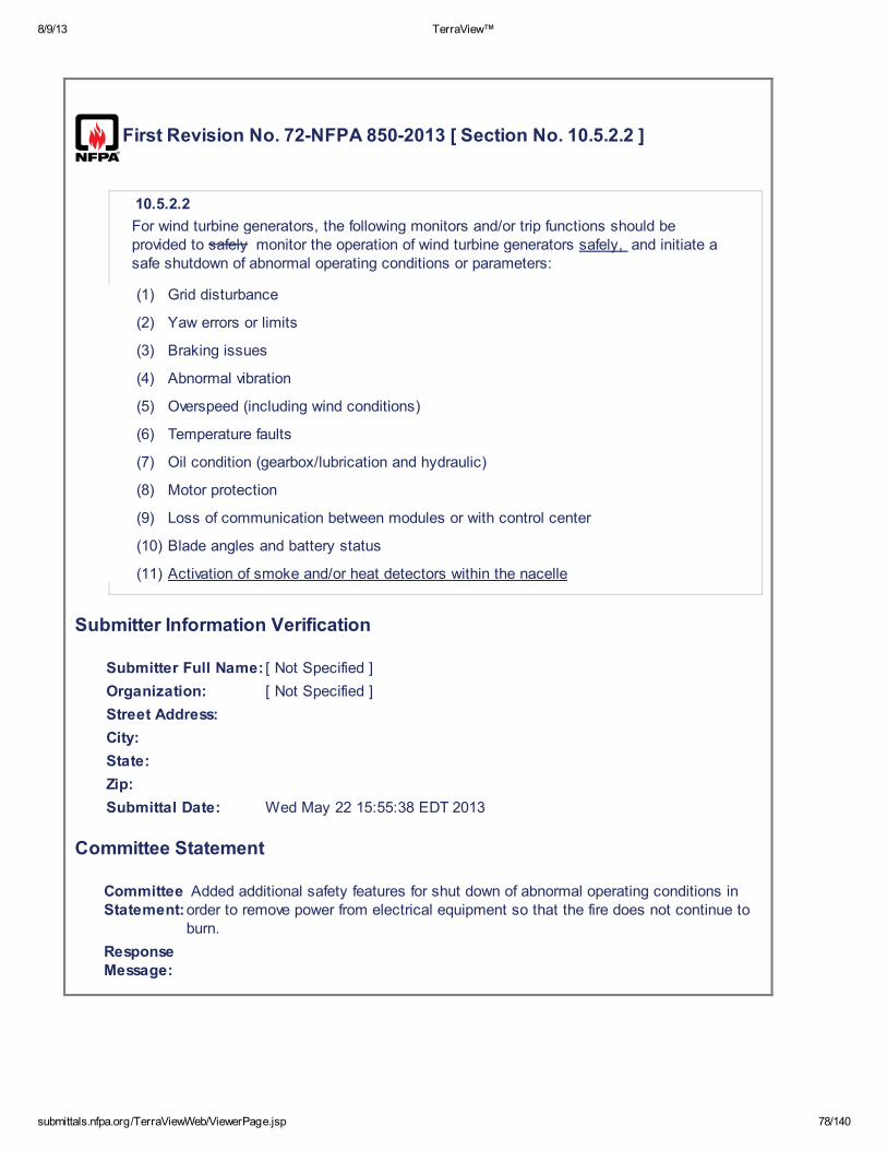
8/9/13 TerraView™
submittals.nfpa.org/TerraViewWeb/ViewerPage.jsp 78/140
First Revision No. 72-NFPA 850-2013 [ Section No. 10.5.2.2 ]
10.5.2.2
For wind turbine generators, the following monitors and/or trip functions should beprovided to safely monitor the operation of wind turbine generators safely, and initiate asafe shutdown of abnormal operating conditions or parameters:
(1) Grid disturbance
(2) Yaw errors or limits
(3) Braking issues
(4) Abnormal vibration
(5) Overspeed (including wind conditions)
(6) Temperature faults
(7) Oil condition (gearbox/lubrication and hydraulic)
(8) Motor protection
(9) Loss of communication between modules or with control center
(10) Blade angles and battery status
(11) Activation of smoke and/or heat detectors within the nacelle
Submitter Information Verification
Submitter Full Name: [ Not Specified ]
Organization: [ Not Specified ]
Street Address:
City:
State:
Zip:
Submittal Date: Wed May 22 15:55:38 EDT 2013
Committee Statement
CommitteeStatement:
Added additional safety features for shut down of abnormal operating conditions inorder to remove power from electrical equipment so that the fire does not continue toburn.
ResponseMessage:
8/9/13 TerraView™
submittals.nfpa.org/TerraViewWeb/ViewerPage.jsp 79/140
First Revision No. 74-NFPA 850-2013 [ Section No. 10.5.2.9 ]
10.5.2.9
Lightning protection for blades, nacelles, towers, power lines, transformers, and supportstructures should be provided in accordance with International ElectrotechnicalCommission (IEC) TR 61400-24, Wind Turbine Generator Systems —Part 24, LightningProtection. NFPA 780, Standard for the Installation of Lightning Protection Systems , orIEC 62305, Protection Against Lightning .
Submitter Information Verification
Submitter Full Name: [ Not Specified ]
Organization: [ Not Specified ]
Street Address:
City:
State:
Zip:
Submittal Date: Wed May 22 16:05:24 EDT 2013
Committee Statement
CommitteeStatement:
IEC TR 61400-24 has been withdrawn therefore new reference material hasbeen provided.
ResponseMessage:
8/9/13 TerraView™
submittals.nfpa.org/TerraViewWeb/ViewerPage.jsp 80/140
First Revision No. 73-NFPA 850-2013 [ Section No. 10.5.3.1.3 ]
10.5.3.1.3
Due to the remote location of the majority of on-shore wind generating facilities and thelack of abundant water supplies, the use of water-based fire protection systems isunlikely. For off-shore facilities, the same is true because the construction of pumpingand fire water distribution systems would be cost prohibitive. If the design of a particularfacility does, however, permit the use of water suppression systems, these systemsshould follow the general recommendations in Chapter 7. If the Fire Protection DesignBasis Document indicates a need for fire-fighting capability using water, NFPA 1142 ,Standard for Water Supplies for Suburban and Rural Fire Fighting , should be consulted.
Submitter Information Verification
Submitter Full Name: [ Not Specified ]
Organization: [ Not Specified ]
Street Address:
City:
State:
Zip:
Submittal Date: Wed May 22 16:02:15 EDT 2013
Committee Statement
CommitteeStatement:
A reference was needed to provide guidance for the user if a water source isneeded in a remote location.
ResponseMessage:

8/9/13 TerraView™
submittals.nfpa.org/TerraViewWeb/ViewerPage.jsp 81/140
First Revision No. 75-NFPA 850-2013 [ New Section after 10.5.3.4.2 ]
Submitter Information Verification
Submitter Full Name: [ Not Specified ]
Organization: [ Not Specified ]
Street Address:
City:
State:
Zip:
Submittal Date: Wed May 22 16:13:18 EDT 2013
Committee Statement
CommitteeStatement:
NFPA 2010 has been recognized as a new technology for providing fireprotection.
Response Message:
First Revision No. 80-NFPA 850-2013 [ Sections 11.1, 11.2, 11.3 ]
11.1* General.
Chapter 11 covers fire hazards associated with solar thermal power generating stations.The process used in current commercial applications typically involves heating heattransfer fluid (HTF) in solar fields and using this fluid to generate steam to drive a steamturbine generator one of two basic technologies: .
(1) Concentrated solar power (CSP), which involves using solar radiation to heat aworking fluid which, in turn, is used to generate steam to drive a steam turbinegenerator.
(2) Photovoltaic (PV) solar power that is associated with the use of PV panels invarious arrays to convert energy from the sun to dc electrical energy that issubsequently converted to ac power for delivery to the grid.
Global FR-80 Hide Deleted
11.2 Application of Chapters 4 through 7, 1516 , and 1617 .
8/9/13 TerraView™
submittals.nfpa.org/TerraViewWeb/ViewerPage.jsp 82/140
11.2.1
The recommendations contained in Chapters 4 through 7 , 15 16 , and 16 17apply. The Fire Protection Design Basis Document should determine whichrecommendations apply to any specific facility. This determination is done by evaluatingthe specific hazards that exist in the facility and evaluating the level of acceptable risk forthe facility. The remaining paragraphs in this chapter provide recommendations that arebeyond the scope of other chapters in this recommended practice.
11.3* Risk Considerations.
11.3.1* Photovoltaic (PV) Power.
Major hazards associated with PV generating plants are as follows:
(1) Electrical fires associated with failed PV module connections or string cabling
(2) Hydraulic oil fires associated with the hydraulic oil systems used for multi-planetracker positioning of the PV modules
(3) Inverter, switchgear, and cable fires
(4) Transformer failure fires
(5) Wildland fires around arrays of PV modules and strings
11.3.2* Concentrated Solar Power.
The major hazards associated with concentrated solar generating plants are as follows:
(1) Release of large quantities of combustible HTF
(2) Shielded fires involving large quantities of HTF in the heater
(3) Lubricating and control oil fires
(4) Switchgear and cable fires
(5) Transformer failure fires
(6) Wildland fires around arrays of solar collection assemblies
11.3.3
Determination should be made with regard to damage that would be caused by a releaseof HTF. Spacing and design of critical equipment and structures should be such so as tolimit damage in the event of a fire exposure in both the solar field and power generationareas.
Submitter Information Verification
Submitter Full Name: [ Not Specified ]
Organization: [ Not Specified ]
Street Address:
City:
State:
Zip:
Submittal Date: Tue May 28 09:59:13 EDT 2013
Committee Statement

8/9/13 TerraView™
submittals.nfpa.org/TerraViewWeb/ViewerPage.jsp 83/140
CommitteeStatement:
Identifies and differentiates fire hazards of Photovoltaic power generating plantsand concentrated solar power plants.
ResponseMessage:
8/9/13 TerraView™
submittals.nfpa.org/TerraViewWeb/ViewerPage.jsp 84/140
First Revision No. 76-NFPA 850-2013 [ Section No. 11.4.1.1 ]
11.4.1.1*
ANSI/ASME B31.1, Power Piping, should be followed in the design of HTF pipingsystems. Piping and fittings should be properly designed to resist an exposure fire untilprotection can be achieved by water spray. To reduce possible sources of leaks, use ofrotating-ball-joint-type connections instead of flexible hose connections Carefulconsideration should be given to the design, application, construction, and installation ofconnections (rotating ball joint, flexible hose, etc.) employed in areas such as the HTFloop connection connections of adjacent solar collector assemblies should beconsidered to prevent possible sources of HTF leaks . Gaskets and seals should becompatible with HTF. Flanges and piping connections on HTF systems should haveguards.
Submitter Information Verification
Submitter Full Name: [ Not Specified ]
Organization: [ Not Specified ]
Street Address:
City:
State:
Zip:
Submittal Date: Wed May 22 17:20:24 EDT 2013
Committee Statement
CommitteeStatement:
Note: This Proposal originates from Tentative Interim Amendment 850-10-1 (TIA 982)issued by the Standards Council on August 5, 2010. The statement in the NFPA 850documentation, “To reduce possible sources of leaks, consider use of rotating-balljoint-type connections instead of flexible hose connections in areas such as theHTF loop connection of adjacent solar collector assemblies”, limits the utilization ofnew technologies. Emergency Nature: The proposed TIA intends to correct acircumstance in which the revised document has resulted in an adverse impact on aproduct or method that was inadvertently overlooked in the total revision process, orwas without adequate technical (safety) justification for the action. Restricting usageof new technologies in parabolic trough is an emergency issue as the current versionlimits and discourages the utilization of new proven technologies. NTF connectionsare highly engineered devises. Fire accidents have occurred when carefulconsideration was not given to the design, application, construction and installationof the connections regardless of the connection type used.
ResponseMessage:
Public Input No. 13-NFPA 850-2012 [Section No. 11.4.1.1]

8/9/13 TerraView™
submittals.nfpa.org/TerraViewWeb/ViewerPage.jsp 85/140
First Revision No. 81-NFPA 850-2013 [ Section No. 11.4.1.7 ]
11.4.1.7
HTF piping and component relief valves should discharge be positioned in such a waythat discharges of either liquid or vapor occur at a location that will limit fire exposure tocritical equipment and/or adjacent equipment or structures .
Submitter Information Verification
Submitter Full Name: [ Not Specified ]
Organization: [ Not Specified ]
Street Address:
City:
State:
Zip:
Submittal Date: Tue May 28 10:38:45 EDT 2013
Committee Statement
CommitteeStatement:
Provide guidance to reduce fire exposure from releases of HTFpiping/component relief valves.
ResponseMessage:
8/9/13 TerraView™
submittals.nfpa.org/TerraViewWeb/ViewerPage.jsp 86/140
First Revision No. 82-NFPA 850-2013 [ New Section after 11.5.1 ]
11.5.2
As solar generating stations are typically located in remote areas, NFPA 1142 ,Standard for Water Supplies for Suburban and Rural Fire Fighting , should be consultedif the design basis indicates the need for water-based fire protection.
Submitter Information Verification
Submitter Full Name: [ Not Specified ]
Organization: [ Not Specified ]
Street Address:
City:
State:
Zip:
Submittal Date: Tue May 28 10:43:44 EDT 2013
Committee Statement
CommitteeStatement:
A reference was needed to provide guidance for the user if a water source isneeded in a remote location.
ResponseMessage:
First Revision No. 83-NFPA 850-2013 [ Sections 11.5.3, 11.5.4 ]
11.5.4
Consideration should be given to the placement of hydrants and monitors Hydrantsshould be placed strategically about the solar field so as to provide strategic coverageof all HTF piping associated with solar collection assemblies and HTF supply anddistribution piping. Based on the completed Fire Protection Design Basis Document, analternative could be the use of fire/water trucks if the site water supply so dictates. Thiswill help in early manual fire- fighting and exposure control and must be in coincidencewith site environmental concerns and plans .
8/9/13 TerraView™
submittals.nfpa.org/TerraViewWeb/ViewerPage.jsp 87/140
11.5.5
An automatic listed fire protection system should be provided for the following areasbased on the Fire Protection Design Basis (where the hazard is lube oil or hydraulic oil, alisted fire-resistant fluid is an acceptable alternative to fixed fire protection):
Lubrication systems
Hydraulic control systems
Electrical equipment rooms, including control, computer, communications, cabletrays, and tunnels, in accordance with Chapter 7
Particular care should be practiced with respect to adequate spatial separation andprotection from wildland fires as well as the control of vegetation where fields of CSPsolar collection assemblies or PV panels might be located. Guidance regardingvegetation clearance, separation distance, and emergency planning can be found inNFPA 1143 , Standard for Wildland Fire Management , and NFPA 1144 , Standard forReducing Structure Ignition Hazards from Wildland Fires .
11.5.6
Per the completed Fire Protection Design Basis Document, an automatic listed firedetection and/or protection system should be provided for the following areas (where thehazard is lube oil or hydraulic oil, a listed fire-resistant fluid is an acceptable alternativeto fixed fire protection):
(1) Lubrication systems
(2) Hydraulic control systems, including those associated with solar collectorassembly and solar panel/module/string tracking systems
(3) Electrical equipment rooms, including control, computer, communications, cabletrays, and tunnels, in accordance with Chapter 7
(4) Inverter cabinets and associated transformers, especially if the solar plant designfeatures a significant concentration of inverters in one location
Submitter Information Verification
Submitter Full Name: [ Not Specified ]
Organization: [ Not Specified ]
Street Address:
City:
State:
Zip:
Submittal Date: Tue May 28 11:23:09 EDT 2013
Committee Statement
CommitteeStatement:
Provide guidance for fire protection of solar generating plants including exposuresassociated with HTF piping systems, fireland fires, hydraulic control systems andinverter cabinets.
Response
8/9/13 TerraView™
submittals.nfpa.org/TerraViewWeb/ViewerPage.jsp 88/140
Message:
First Revision No. 90-NFPA 850-2013 [ Section No. 12.2 ]
12.2 Application of Chapters 4 through 7, 15 16 , and 16 17 .
12.2.1*
The recommendations contained in Chapters 4 through 7, 15 16 , and 16 17 apply toall geothermal power plants (direct steam, flash steam, and binary). The Fire ProtectionDesign Basis Document should determine which recommendations apply to any specificfacility. This determination is done by evaluating the specific hazards that exist in thefacility and evaluating the level of acceptable risk for the facility. The remainder of thischapter provides recommendations that are not included in other chapters in thisrecommended practice.
12.2.2
In general, risk considerations for direct steam and flash steam geothermal plants are thesame as those for conventional steam turbine power plants. For binary plants, thedifferences are provided below in this chapter. The major Major hazards are as follows:
(1) Lubricating and control oil fires
(2) Combustible cooling tower construction
(3) Switchgear and cable fires
Submitter Information Verification
Submitter Full Name: [ Not Specified ]
Organization: [ Not Specified ]
Street Address:
City:
State:
Zip:
Submittal Date: Thu May 30 11:42:35 EDT 2013
Committee Statement
CommitteeStatement:
Editorial. A new chapter 14 was added moving chapters 15 and 16 to 16and 17.
Response Message:

8/9/13 TerraView™
submittals.nfpa.org/TerraViewWeb/ViewerPage.jsp 89/140
First Revision No. 91-NFPA 850-2013 [ Section No. 13.2 ]
13.2 Application of Chapters 4 through 7, 15 16 , and 16 17 .
The recommendations contained in Chapters 4 through 7, 16, and 17 readily apply toIGCC facilities. With the addition of the different technologies involved in syngasproduction and the differences in syngas with respect to natural gas, the Fire ProtectionDesign Basis Document should determine which recommendations apply to any specificIGCC facility. This determination is done by evaluating the specific hazards that exist inthe facility and evaluating the level of acceptable risk for the facility. For IGCC facilities, itis expected that most of the recommendations will apply, although there could beparticular plants for which some of the recommendations will not apply since the hazardsdescribed might not exist (e.g., no air separation unit). The user is responsible fordetermining the properties of the materials used or generated in the facility (vapordensity, ignition temperature, LFL, etc.). It is recommended that designers seekguidance from those having specialized experience to understand the uniquecharacteristics of any particular fuel or technology in order to properly apply theappropriate portions of this and other applicable documents.
Submitter Information Verification
Submitter Full Name: [ Not Specified ]
Organization: [ Not Specified ]
Street Address:
City:
State:
Zip:
Submittal Date: Thu May 30 11:43:25 EDT 2013
Committee Statement
CommitteeStatement:
Editorial. A new chapter 14 was added moving chapters 15 and 16 to 16and 17.
Response Message:
First Revision No. 87-NFPA 850-2013 [ New Section after 13.9.2 ]
Chapter 14 Identification and Protection of Hazards for Hydroelectric Generating Plants
14.1 General.
8/9/13 TerraView™
submittals.nfpa.org/TerraViewWeb/ViewerPage.jsp 90/140
14.1.1
Chapter 14 identifies fire and explosion hazards of hydroelectric generating stations.Such facilities include both dam-type facilities using penstocks to direct water tovertical-type hydro turbine generators and run-of-the-river facilities in which river water ischanneled through axial-type hydro turbine generators. In addition, pumped-storagehydro facilities operate as normal vertical (upper storage to lower storage) hydro stationsto produce electrical power and pump water from the lower storage to the upper storage.This chapter specifies recommended protection criteria for all three types ofhydroelectric stations.
14.2 Application of Chapters 4 through 7 and 16 and 17.
The recommendations contained in Chapters 4 through 7 , 16 , and 17 can applyto HVDC converter stations and SVC/SVG. The Fire Protection Design Basis Documentwill determine which recommendations apply to any specific HVDC or SVC/SVG facility.This determination is done by evaluating the specific hazards that exist in the facilityand determining the level of acceptable risk for the facility. It is expected that mostrecommendations will apply to all HVDC, SVC/SVG, and VFT facilities.
14.3 General Design and Equipment Arrangement.
14.3.1
Adequate separation should be provided between the following, as determined by theFire Protection Design Basis Document:
(1) To separate the intake hoist housing from generator floor area and from adjacentareas
(2) To separate dam and spillway hoists, including the main power and backuppower bus, from adjacent areas such as spillway electrical distribution rooms
(3) To separate the tailrace service gallery from turbine/generator floors and governorhydraulic equipment
14.3.2*
Ventilation exhaust systems, particularly those for subsurface portions of undergroundfacilities, should have fans able to operate continually to exhaust smoke and chemicalfumes that can result from fires or from extinguishing of fires. The design and selectionof the fans and other elements of the system should take into account additionalventilation needs for removing smoke and high-temperature gases. Therefore the fanand its associated components, along with any ductwork, should be capable ofhandling high temperatures without deforming. The specific weight and volume of theheated air during a fire and the climatic conditions should also be considered. Total fancapacity should be provided so that ventilation requirements can be met with thelargest fan out of service.
14.3.3
Fire hazards should not be located in the principal access or air supply (e.g., conduits,shafts, tunnels) in order to avoid loss of fresh air in the event of a fire.
14.3.4
An emergency power supply should be provided for principal drainage pumps in areaswhere flooding would be dangerous.
14.4 Unattended Facilities.
14.4.1
Hydroelectric plants that are operated unattended or with minimal staffing presentspecial fire protection concerns.

8/9/13 TerraView™
submittals.nfpa.org/TerraViewWeb/ViewerPage.jsp 91/140
14.4.2
Consideration should be given both to the delayed response time of the fire brigade orpublic fire-fighting personnel (which can be several hours) and to the lack of personnelavailable to alert others on site to a fire condition.
14.4.3
The fire risk evaluation should address delayed response and lack of communication.This might establish the need to provide additional fire protection measures to preventa major fire spread prior to the arrival of fire-fighting personnel. The delayed responseby personnel to the site can necessitate automatic shutoff of fire pumps.
14.4.4
If automatic water-based fire suppression systems are utilized, a cycling deluge valveshould be considered. The arrangement will depend on the type of system and thehazard protected. Thermal detection is recommended. System design should be inaccordance with NFPA 13, Standard for the Installation of Sprink ler Systems , orNFPA 15, Standard for Water Spray Fixed Systems for Fire Protection .
14.4.5
Remote annunciation of the fire signaling panel to one or more constantly attendedlocations is critical for emergency response. The fire signaling panel should belocated at the entry to the plant. Special consideration should be given to alertingpersonnel in confined spaces, such as in scroll/spiral cases or draft tubes, that a firealarm system has been activated.
14.4.6
An emergency lighting system for critical operating areas that depends on batteries orfuel supplies should be manually operated from a switch at the entry to the plant. Theemergency lighting can be permitted to consist either of fixed units or of portablelights (see 5.6.2 ).
14.4.7
It is important that the responding fire brigade or public fire-fighting forces be familiarwith access, plant fire protection systems, emergency lighting, specific hazards, andmethods of fire control. This should be reflected in the plant fire emergency plan (see9.4.4 ).
14.4.8
The air supply and exhaust systems for the plant should be shut down automaticallyin the event of a fire. Manual override should be located at the entry to the plant sothat emergency responders can activate these controls upon arrival.
14.5 Identification and Protection of Hazards.
14.5.1 General.
The identification and selection of fire protection systems should be based on the firerisk evaluation. This chapter identifies fire and explosion hazards in hydroelectricgenerating stations and specifies the recommended protection criteria unless the firerisk evaluation indicates otherwise.
14.5.2 Turbine-Generator Hydraulic Control and Lubricating Oil Systems.
14.5.2.1 Hydraulic Control Systems.
14.5.2.1.1
Hydraulic control systems should use a listed fire-resistant fluid.
14.5.2.1.2
Determination of the need for fire-resistant fluid should be based on the quantity offluid involved in the system, whether or not equipment that utilizes this fluid willoperate hot or be exposed to external sources of ignition, and whether exposureproblems are created for adjacent equipment by the use of non-fire-resistant fluid.

8/9/13 TerraView™
submittals.nfpa.org/TerraViewWeb/ViewerPage.jsp 92/140
14.5.2.1.3
If a listed fire-resistant fluid is not used, hydraulic control equipment should beprotected. Fire extinguishing systems, where installed for hydraulic controlequipment, should include protection for reservoirs, other equipment, valves, andassociated piping.
14.5.2.2
Wherever possible, oil piping should be welded and flanged to minimize thepossibility of an oil leak due to severe vibration.
14.5.2.3
Oil piping should be routed away, or be shielded, from electrical equipment or othersources of ignition.
14.5.2.4*
Fixed fire protection for this equipment, where provided, should be as follows:
(1) Automatic wet pipe sprinkler protection systems utilizing a design density of
0.25 gpm/ft 2 (10.2 mm/min) for the entire hazard area
(2) Automatic foam-water sprinkler systems providing a density of 0.16 gpm/ft 2
(6.5 mm/min)
(3) Gaseous extinguishing systems of either the local application or total floodingtypes. Safety considerations associated with these systems should beevaluated prior to the selection of gas-type protection systems.
(4) Compressed air-foam systems designed and installed in accordance withNFPA 11, Standard for Low-, Medium-, and High-Expansion Foam , and theirlisting for the specific hazards and protection objectives specified in the listing
14.5.2.5
Consideration for protection of horizontal and vertical turbine bearings should bemade based on the Fire Protection Design Basis Document.
14.5.2.6
Curbs [minimum 6 in. (0.15 m) high], drains, or both should be provided for the oilstorage and oil purification areas in accordance with Chapter 5 .
14.5.2.7
Fire extinguishing systems, where installed for lube oil systems employingcombustible-type oil, should include protection for the reservoirs, pumps, and all oillines, especially where unions exist on piping and beneath any shielded area whereflowing oil can collect. Facilities not provided with curbs or drains should extendcoverage for a distance of 20 ft (6 m) from the oil lines, when measured from theoutermost oil line.
14.5.2.8
Clean or dirty oil storage areas should be protected based on the fire risk evaluation.These areas generally represent the largest concentrated oil storage in the plant.The designer should consider, at a minimum, the installation of fixed automatic fireprotection systems and the ventilation and drainage requirements in Chapter 5 .
14.5.3 Generator Pit and Windings.
14.5.3.1*
Protection of generator windings consisting of materials that will not extinguish whende-energized should be provided by automatically actuated gaseous extinguishingsystems, water spray rings, or both.
8/9/13 TerraView™
submittals.nfpa.org/TerraViewWeb/ViewerPage.jsp 93/140
14.5.3.2
Fire detection in generator winding should be provided.
14.5.3.3
Protection of generator pits containing auxiliary circuits such as protection currenttransformers (CTs), neutral transformers, and grounding resistors that are associatedwith generator protection should be provided by an automatically actuated gaseousextinguishing system or water spray system.
14.5.3.4
Gaseous suppression systems should be actuated by protective relays, firedetection systems, or both.
14.5.3.5
Operation of water spray rings should be interlocked so that the unit will trip beforethe water spray system activates. Immediately after the generator has been sprayedwith a water-based system, it should be mechanically run (electrically isolated andwithout excitation) for at least 24 hours to avoid creating stator ground faults on bothtypes of winding materials.
14.5.4 Cable Concentrations.
14.5.4.1
Consideration should be given to the use of fire-retardant cable insulation such asthose passing the flame propagation test in IEEE-1202, Standard for Flame-Propagation Testing of Wire and Cable .
14.5.4.2
Areas with significant concentrations of combustible cable jacketing or oil-filled cableshould be protected with automatic sprinkler, water spray, or water mist systems.However, if water-type systems cannot be used, foam or gaseous extinguishingsystems should be provided.
14.5.4.3
Sprinkler or water spray systems should be designed for a density of 0.30 gpm/ft 2
(12.2 mm/min) over 2500 ft 2 (232 m 2 ). This coverage is for area protection.Individual cable tray tier coverage could be required based on the fire risk evaluation.
14.6 Cable Tunnels.
14.6.1
Where protection is required by the fire risk evaluation, cable tunnels should beprotected by automatic water spray, automatic wet pipe sprinkler, or foam-waterspray systems. Automatic sprinkler systems should be designed for a density of
0.30 gpm/ft 2 (12.2 mm/min) over 2500 ft 2 (232 m 2 ) or the most remote 100
linear ft (30.5 m) of cable tunnel up to 2500 ft 2 (232 m 2 ).
14.6.2
Portable high-expansion foam generators can be permitted to be used to supplementa fixed fire protection system(s). (See NFPA 1901, Standard for Automotive FireApparatus.)
14.6.3
Ventilation and drainage should be provided for these areas in accordance withChapter 5 .
14.6.4 Indoor Oil-filled Electrical Equipment.
Automatic sprinkler, foam-water spray, water spray, and compressed air-foamsystems should be considered for oil-filled electrical equipment. Where the hazard isnot great enough to warrant a fixed fire suppression system, automatic fire detectionshould be considered (see 6.7.2 ) .
8/9/13 TerraView™
submittals.nfpa.org/TerraViewWeb/ViewerPage.jsp 94/140
14.6.5 Air Compressors.
Automatic sprinkler protection designed for a density of 0.25 gm/ft 2 (10.2 mm/min)over the postulated oil spill or compressed air foam should be considered for aircompressors containing a large quantity of oil. Compressed air foam systems shouldbe designed and installed in accordance with NFPA 11, Standard for Low-, Medium-,and High-Expansion Foam , and their listing for the specific hazards and protectionobjectives specified in the listing. Where the hazard is not great enough to warrant afixed-fire suppression system, automatic fire detection should be considered (see6.7.2 ) .
14.6.6 Hydraulic Systems for Gate and Valve Operators.
Hydraulic systems for gate and valve operators should be designed in accordancewith 14.5.2.1 . Where the hazard is not great enough to warrant a fixed firesuppression system, automatic fire detection should be considered (see 6.7.2 ) .
Submitter Information Verification
Submitter Full Name: [ Not Specified ]
Organization: [ Not Specified ]
Street Address:
City:
State:
Zip:
Submittal Date: Tue May 28 15:00:08 EDT 2013
Committee Statement
CommitteeStatement:
NFPA 851 was incorporated into NFPA 850 to match how other means of electricgenerating facilities have been incorporated. Since the majority of therecommendations in NFPA 850 and NFPA 851 were the same where similar hazardwere being addressed. Where there were recommendations that applied specificallyto hydroelectric generating facilities, that criterion was included in the new chapter14. The recommendations that are the same already exist in NFPA 850. Historically,there has been the same recommendation in one document that did not get changedduring a revision. This provided for confusion and misunderstanding. Theincorporation of the documents will address this situation. Existing chapters 15 and16 are to be renumbered as chapters 16 and 17 including annex material.
ResponseMessage:
8/9/13 TerraView™
submittals.nfpa.org/TerraViewWeb/ViewerPage.jsp 95/140
First Revision No. 92-NFPA 850-2013 [ Section No. 14.2 ]
15.2 Application of Chapters 4 through 7, 15 16 , and 16 17 .
The recommendations contained in Chapters 4 through 7, 15 16 , and 16 17 can applyto HVDC converter stations and SVC/SVG. The Fire Protection Design Basis Documentwill determine which recommendations apply to any specific HVDC or SVC/SVG facility.This determination is done by evaluating the specific hazards that exist in the facility anddetermining the level of acceptable risk for the facility. It is expected that mostrecommendations will apply to all HVDC, SVC/SVG, and VFT facilities.
Submitter Information Verification
Submitter Full Name: [ Not Specified ]
Organization: [ Not Specified ]
Street Address:
City:
State:
Zip:
Submittal Date: Thu May 30 11:44:05 EDT 2013
Committee Statement
CommitteeStatement:
Editorial. A new chapter 14 was added moving chapters 15 and 16 to 16and 17.
Response Message:
First Revision No. 94-NFPA 850-2013 [ Section No. 15.3 ]
16.3 Site Clearing, Excavation, Tunneling, and Construction Equipment.
16.3.1 Site Clearing.
16.3.1.1
Prior to clearing forest and brush-covered areas, the owner should ensure that a writtenfire control plan is prepared and that fire-fighting tools and equipment are made availableas recommended by NFPA 1143, Standard for Wildland Fire Management. Contactshould be made with local fire and forest agencies for current data on restrictions and firepotential, and to arrange for necessary permits.
16.3.1.2
All construction vehicles and engine-driven portable equipment should be equipped witheffective spark arresters. Vehicles equipped with catalytic converters should be prohibitedfrom wooded and heavily vegetated areas.

8/9/13 TerraView™
submittals.nfpa.org/TerraViewWeb/ViewerPage.jsp 96/140
16.3.1.3
Fire tools and equipment should be used for fire emergencies only and should bedistinctly marked and maintained in a designated area.
16.3.1.4
Each site utility vehicle should be equipped with at least a portable fire extinguisher orbackpack pump filled with 4 gal to 5 gal (15 L to 19 L) of water.
16.3.1.5
Cut trees, brush, and other combustible spoil should be disposed of promptly.
16.3.1.6
Where it is necessary to dispose of combustible waste by on-site burning, designatedburning areas should be established with approval by the owner and should be incompliance with federal, state, and local regulations and guidelines. The contractorshould coordinate burning with the agencies responsible for monitoring fire danger in thearea and should obtain all appropriate permits prior to the start of work. (See Section16.2.)
16.3.1.7
Local conditions can require the establishment of fire breaks by clearing or use ofselective herbicides in areas adjacent to property lines and access roads.
Global FR-93 Hide Deleted
16.3.2 Excavation and Tunneling.
16.3.2.1
Construction activities related to tunnels, shafts, and other underground excavations arestrictly regulated by federal and state agencies. Fire prevention consists of adequateventilation, good housekeeping, and limiting the types of fuel, explosives, andcombustibles underground as well as adjacent to entrances and ventilation intakes.Inspections of site conditions and the testing of air quality should be assigned toqualified personnel specifically trained in the use of those instruments specified by theregulating agency.
16.3.2.2
Pre-excavation geologic surveys should include tests for carbonaceous or oil-bearingstrata, peat, and other organic deposits that can be a source of combustible dusts orexplosive gases.
16.3.2.3
The use of vehicles and equipment requiring gasoline, liquefied petroleum gas, and otherfuels in excavations with limited air circulation should be restricted.
16.3.2.4
A general plan of action for use in times of emergency should be prepared for everyunderground excavation. (See Section 1.2 .)
16.3.2.5 Construction Equipment.
Construction equipment should meet the requirements of NFPA 120, Standard for FirePrevention and Control in Coal Mines .
Submitter Information Verification
Submitter Full Name: [ Not Specified ]
Organization: [ Not Specified ]
Street Address:
City:
State:

8/9/13 TerraView™
submittals.nfpa.org/TerraViewWeb/ViewerPage.jsp 97/140
Zip:
Submittal Date: Thu May 30 13:24:26 EDT 2013
Committee Statement
Committee Statement: Incorporated recommendations from NFPA 851.
Response Message:

8/9/13 TerraView™
submittals.nfpa.org/TerraViewWeb/ViewerPage.jsp 98/140
First Revision No. 93-NFPA 850-2013 [ New Section after 15.3.1.7 ]
Global FR-93 Hide Deleted
16.3.2 Excavation and Tunneling.
16.3.2.1
Construction activities related to tunnels, shafts, and other underground excavations arestrictly regulated by federal and state agencies. Fire prevention consists of adequateventilation, good housekeeping, and limiting the types of fuel, explosives, andcombustibles underground as well as adjacent to entrances and ventilation intakes.Inspections of site conditions and the testing of air quality should be assigned toqualified personnel specifically trained in the use of those instruments specified by theregulating agency.
16.3.2.2
Pre-excavation geologic surveys should include tests for carbonaceous or oil-bearingstrata, peat, and other organic deposits that can be a source of combustible dusts orexplosive gases.
16.3.2.3
The use of vehicles and equipment requiring gasoline, liquefied petroleum gas, and otherfuels in excavations with limited air circulation should be restricted.
16.3.2.4
A general plan of action for use in times of emergency should be prepared for everyunderground excavation. (See Section 1.2 .)
16.3.2.5 Construction Equipment.
Construction equipment should meet the requirements of NFPA 120, Standard for FirePrevention and Control in Coal Mines .
Submitter Information Verification
Submitter Full Name: [ Not Specified ]
Organization: [ Not Specified ]
Street Address:
City:
State:
Zip:
Submittal Date: Thu May 30 13:22:18 EDT 2013
Committee Statement
Committee Statement: Incorporated recommendations from NFPA 851.
Response Message:
8/9/13 TerraView™
submittals.nfpa.org/TerraViewWeb/ViewerPage.jsp 99/140
First Revision No. 95-NFPA 850-2013 [ Section No. 15.4.2 ]
16.4.2
Construction warehouses, offices, trailers, sheds, and other facilities for the storage oftools and materials should be located with consideration of their exposure to major plantbuildings or other important structures. ( For guidance in separation and protection, seeNFPA 80A, Recommended Practice for Protection of Buildings from Exterior FireExposures, and NFPA 1144, Standard for Reducing Structure Ignition Hazards fromWildland Fire. .)
Submitter Information Verification
Submitter Full Name: [ Not Specified ]
Organization: [ Not Specified ]
Street Address:
City:
State:
Zip:
Submittal Date: Thu May 30 13:31:54 EDT 2013
Committee Statement
Committee Statement: Incorporated recommendations from NFPA 851.
Response Message:
8/9/13 TerraView™
submittals.nfpa.org/TerraViewWeb/ViewerPage.jsp 100/140
First Revision No. 96-NFPA 850-2013 [ Section No. 15.4.3 ]
16.4.3
Large central office facilities can be of substantial value and contain high-value computerequipment, irreplaceable construction records, or other valuable contents, the loss ofwhich can result in significant construction delays. An analysis of fire potential should beperformed. This analysis can indicate a need for automatic sprinkler systems or otherprotection, fire/smoke detection, or the desirability of subdividing the complex to limitvalues exposed by one fire, or a combination of the above.
Submitter Information Verification
Submitter Full Name: [ Not Specified ]
Organization: [ Not Specified ]
Street Address:
City:
State:
Zip:
Submittal Date: Thu May 30 13:35:07 EDT 2013
Committee Statement
Committee Statement: Incorporated recommendations from NFPA 851.
Response Message:
8/9/13 TerraView™
submittals.nfpa.org/TerraViewWeb/ViewerPage.jsp 101/140
First Revision No. 97-NFPA 850-2013 [ Section No. 15.4.7 ]
16.4.7
Construction camps comprised of mobile buildings arranged with the buildings adjoiningeach other to form one large fire area should be avoided. If buildings cannot be separatedadequately separated , consideration should be given to installing fire walls between unitsor installing automatic sprinklers throughout the buildings.
16.4.7.1
Mobile buildings should be installed and located according to the requirements of NFPA501A , Standard for Fire Safety Criteria for Manufactured Home Installations, Sites, andCommunities . Insulating materials utilized in mobile buildings should benoncombustible.
16.4.7.2
Construction camp buildings should be designed and installed in accordance withNFPA 101 , Life Safety Code .
Submitter Information Verification
Submitter Full Name: [ Not Specified ]
Organization: [ Not Specified ]
Street Address:
City:
State:
Zip:
Submittal Date: Thu May 30 13:37:32 EDT 2013
Committee Statement
Committee Statement: Incorporated recommendations from NFPA 851.
Response Message:
8/9/13 TerraView™
submittals.nfpa.org/TerraViewWeb/ViewerPage.jsp 102/140
First Revision No. 98-NFPA 850-2013 [ New Section after 15.4.8 ]
16.4.8.1
The location for central alarm control should be provided with the following:
(1) Remote fire pump start button
(2) Manual siren start/stop button
(3) Provision for alerting the fire crew by radio, fire alert paging, and so forth
(4) Monitors for communication between security guard and fire crew at place of fire
(5) Radio link between security guards' office and the respective fire department
Submitter Information Verification
Submitter Full Name: [ Not Specified ]
Organization: [ Not Specified ]
Street Address:
City:
State:
Zip:
Submittal Date: Thu May 30 13:41:17 EDT 2013
Committee Statement
Committee Statement: Incorporated recommendations from NFPA 851.
Response Message:
8/9/13 TerraView™
submittals.nfpa.org/TerraViewWeb/ViewerPage.jsp 103/140
First Revision No. 99-NFPA 850-2013 [ New Section after 15.4.10 ]
16.4.11
Construction kitchens should be protected in accordance with NFPA 96 , Standard forVentilation Control and Fire Protection of Commercial Cook ing Operations .
Submitter Information Verification
Submitter Full Name: [ Not Specified ]
Organization: [ Not Specified ]
Street Address:
City:
State:
Zip:
Submittal Date: Fri May 31 07:47:51 EDT 2013
Committee Statement
Committee Statement: Incorporated recommendations from NFPA 851.
Response Message:

8/9/13 TerraView™
submittals.nfpa.org/TerraViewWeb/ViewerPage.jsp 104/140
First Revision No. 100-NFPA 850-2013 [ Section No. 15.6.1 [Excluding
any Sub-Sections] ]
Noncombustible or fire-retardant scaffolds, form work, decking, and partitions should beused both inside and outside of permanent buildings where a fire could cause substantialdamage or delay construction schedules. Consideration should be given to providingsprinkler protection for combustible form work where a fire could cause substantialdamage or construction delays.
Submitter Information Verification
Submitter Full Name: [ Not Specified ]
Organization: [ Not Specified ]
Street Address:
City:
State:
Zip:
Submittal Date: Fri May 31 07:51:41 EDT 2013
Committee Statement
Committee Statement: Incorporated recommendations from NFPA 851.
Response Message:
8/9/13 TerraView™
submittals.nfpa.org/TerraViewWeb/ViewerPage.jsp 105/140
First Revision No. 101-NFPA 850-2013 [ Section No. 15.7.3.2 ]
16.7.3.2
As fixed water extinguishing systems are completed, they should be Fixed systemsshould be provided as soon as construction allows, and placed in service, even when theavailable construction phase fire protection water supply is not adequate to meet thesystem design demand. The extinguishing system will at least provide some degree ofprotection, especially where the full hazard is not yet present. However, when thepermanent hazard is introduced, the water supply should be capable of providing thedesigned system demand. When using construction water in permanent systems,adequate strainers should be provided to prevent clogging of the system by foreignobjects and dirt.
Submitter Information Verification
Submitter Full Name: [ Not Specified ]
Organization: [ Not Specified ]
Street Address:
City:
State:
Zip:
Submittal Date: Fri May 31 08:04:38 EDT 2013
Committee Statement
Committee Statement: Incorporated recommendations from NFPA 851.
Response Message:

8/9/13 TerraView™
submittals.nfpa.org/TerraViewWeb/ViewerPage.jsp 106/140
First Revision No. 64-NFPA 850-2013 [ Section No. 16.2.2 ]
17.2.2
Proper preventative preventive maintenance of operating equipment as well as andadequate operator training are critical aspects of a viable an effective fire preventionprogram. See Annex D for examples of operator errors causing significant property loss.
Submitter Information Verification
Submitter Full Name: [ Not Specified ]
Organization: [ Not Specified ]
Street Address:
City:
State:
Zip:
Submittal Date: Wed May 22 14:05:49 EDT 2013
Committee Statement
CommitteeStatement:
Emphasizes the importance of operator training in fire/loss prevention, andprovides direction to see Annex for examples.
ResponseMessage:
First Revision No. 65-NFPA 850-2013 [ Section No. 16.3 ]
8/9/13 TerraView™
submittals.nfpa.org/TerraViewWeb/ViewerPage.jsp 107/140
17.3 Fire Risk Control Program.
A written plant fire prevention program should be established and as at a minimumshould include the following:
(1) Fire safety information for all employees and contractors. This information shouldinclude, as at a minimum, familiarization with fire prevention procedures, plantemergency alarms and procedures, and how to report a fire. This should be includedin employee/contractor orientation.
(2) Documented, regularly scheduled plant inspections including provisions for handlingof remedial actions to correct conditions that increase fire hazards.
(3) A description of the general housekeeping practices and the control of transientcombustibles. Fire experience has shown that transient combustibles can be asignificant factor during a fire situation, especially during outages.
(4) Control of flammable and combustible liquids and gases in accordance withappropriate NFPA standards.
(5) Combustible dust, as applicable, in accordance with NFPA 654, Standard for thePrevention of Fire and Dust Explosions from the Manufacturing, Processing, andHandling of Combustible Particulate Solids .
(6) Control of ignition sources including smoking, grinding, welding, and cutting. ( SeeNFPA 51B, Standard for Fire Prevention During Welding, Cutting, and Other HotWork ..)
(7) Fire prevention surveillance. ( See NFPA 601, Standard for Security Services in FireLoss Prevention..)
(8) Fire A fire report, including an investigation and a statement on the corrective actionto be taken. (See see Annex B).
(9) Fire hazards of materials located in the plant or storage areas identified inaccordance with NFPA 704, Standard System for the Identification of the Hazardsof Materials for Emergency Response, and applicable material safety data sheets(MSDS).
Submitter Information Verification
Submitter Full Name: [ Not Specified ]
Organization: [ Not Specified ]
Street Address:
City:
State:
Zip:
Submittal Date: Wed May 22 14:08:58 EDT 2013
Committee Statement
CommitteeStatement:
Provides additional item for consideration in the Fire Risk ControlProgram.
Response Message:
8/9/13 TerraView™
submittals.nfpa.org/TerraViewWeb/ViewerPage.jsp 108/140
First Revision No. 31-NFPA 850-2013 [ Section No. A.5.1.4.2(9) ]
A.5.1.4.2(9)
Oil-filled transformers explosions and fires can be prevented in some cases by theinstallation of a passive mechanical system designed to depressurize the transformer afew milliseconds after the occurrence of an electrical fault. This fast depressurization canbe achieved by a quick oil evacuation triggered by the dynamic pressure peak generatedby the short circuit. The protection technology activates within milliseconds before staticpressure increases, therefore preventing transformer explosion and subsequent fire.However, since these devices do not eliminate a fire potential resulting from all forms oftransformer failure (e.g., transformer bushing failure), they should be considered as apossible supplement to passive protection features such as physical barriers or spatialseparation, not as an alternative to these features.
Submitter Information Verification
Submitter Full Name: [ Not Specified ]
Organization: [ Not Specified ]
Street Address:
City:
State:
Zip:
Submittal Date: Wed May 22 08:39:23 EDT 2013
Committee Statement
CommitteeStatement:
Provides clarification that the fast depressurization system should not be asubstitute for other criteria listed.
ResponseMessage:
First Revision No. 122-NFPA 850-2013 [ Section No. A.5.2.2 ]
8/9/13 TerraView™
submittals.nfpa.org/TerraViewWeb/ViewerPage.jsp 109/140
A.5.2.2
It generally is recognized that boiler and turbine buildings, protected in accordance withthis document, meet the intent of NFPA 101, Life Safety Code, for additional traveldistances for fully sprinklered facilities.
NFPA 101 allows additional means of egress components for special-purpose industrialoccupancies. These areas can be permitted to be provided with fixed industrial stairs,fixed ladders (see ANSI A1264.1, Safety Requirements for Workplace Floor and WellOpenings, Stairs, and Railing Systems, and ANSI A14.3, Standard for SafetyRequirements for Fixed Ladders), or alternating tread devices (see NFPA 101). Examplesof these spaces include catwalks, floor areas, or elevated platforms that are provided formaintenance and inspection of in-place equipment.
Spaces internal to equipment and machinery are excluded from the requirements ofNFPA 101. Examples of these spaces include, but are not limited to, the internals of thefollowing:
(1) Boilers
(2) Scrubbers
(3) Pulverizers
(4) Combustion turbine enclosures
(5) Cooling towers
(6) Bunkers, silos, and hoppers
(7) Conveyor pulley take-up areas
(8) Electrostatic precipitators
Examples of these spaces within hydroelectric plants include the following:
(1) Turbine scroll cases
(2) Generators
(3) Access tunnels for dam inspections
(4) Entry into draft tubes
(5) Penstocks
Submitter Information Verification
Submitter Full Name: [ Not Specified ]
Organization: [ Not Specified ]
Street Address:
City:
State:
Zip:
Submittal Date: Thu Jun 06 08:36:27 EDT 2013
Committee Statement
Committee The recommendation for hydroelectric generating plants has been
8/9/13 TerraView™
submittals.nfpa.org/TerraViewWeb/ViewerPage.jsp 110/140
Statement: incorporated into NFPA 850.
ResponseMessage:
First Revision No. 120-NFPA 850-2013 [ New Section after A.5.4.1.3.2 ]
A.5.5.1
For hydroelectric plants, draining the space above the turbine head cover by gravitymight not be possible. Both ac and dc drainage pumps discharging into piping leading tothe station sump are often provided with suctions in the well where the shaft firstextends above the gland seal. In addition, gravity drainage might be impossible fromsome of the enclosed volumes of bulb units. In such cases, accumulated liquids from oilspills and from fire suppression should be pumped to sumps or to other containmentvolumes.
Submitter Information Verification
Submitter Full Name: [ Not Specified ]
Organization: [ Not Specified ]
Street Address:
City:
State:
Zip:
Submittal Date: Wed Jun 05 10:55:47 EDT 2013
Committee Statement
Committee Statement: Incorporated from NFPA 851.
Response Message:
8/9/13 TerraView™
submittals.nfpa.org/TerraViewWeb/ViewerPage.jsp 111/140
First Revision No. 121-NFPA 850-2013 [ Section No. A.5.5.2 ]
A.5.5.2
Design discharge for the turbine building should be based on the expected timenecessary to take the turbine off line and put it on turning gear, but not less than 10minutes. The provisions are for drainage and any associated drainable facilities (pits,sumps, drains to downstream surge chamber and/or tail tunnels or tailrace, and sumppumps) for underground power plants.
Submitter Information Verification
Submitter Full Name: [ Not Specified ]
Organization: [ Not Specified ]
Street Address:
City:
State:
Zip:
Submittal Date: Wed Jun 05 11:27:27 EDT 2013
Committee Statement
Committee Statement: Incorporated from NFPA 851.
Response Message:

8/9/13 TerraView™
submittals.nfpa.org/TerraViewWeb/ViewerPage.jsp 112/140
First Revision No. 27-NFPA 850-2013 [ New Section after A.6.2.1 ]
A.6.7.3(2)
Special consideration should be given to alerting personnel in remote spaces, such asin scroll/spiral cases or draft tubes.
Submitter Information Verification
Submitter Full Name: [ Not Specified ]
Organization: [ Not Specified ]
Street Address:
City:
State:
Zip:
Submittal Date: Tue May 21 16:23:18 EDT 2013
Committee Statement
CommitteeStatement:
Recommended practice criteria incorporated from NFPA 851 and editoriallyrevised for clarity.
ResponseMessage:
First Revision No. 36-NFPA 850-2013 [ New Section after A.6.2.1 ]
8/9/13 TerraView™
submittals.nfpa.org/TerraViewWeb/ViewerPage.jsp 113/140
A.6.2.2
A single water source could be designed to provide an acceptable level of reliability forthe fire protection system(s). As an example, a single reliable water source couldsupply the fire pump(s). The need for multiple or a secondary water source is dependenton several factors and a detailed analysis of the facility, and the level of reliabilityneeded should be part of the Fire Protection Design Basis Document.
The detailed analysis of the water supply reliability needed should include, but not belimited to, the following:
(1) Reliability of source — under normal circumstances, not including a regionalevent, the water source is expected to operate as designed.
(2) Capacity of source — meets all requirements pertinent to the applicable codesand standards for fixed fire protection and manual fire-fighting.
(3) Reliance on water-based fire protection systems — if the facility reliescompletely on water-based fixed protection systems, then the water supplyreliability is paramount to the success of the overall fire protection systemdesign. A single, credible impairment should not eliminate the water supply fromthe fire protection system.
(4) Availability of alternate and back-up sources — additional water sources such asconnections to the public water supply, cooling tower basins, service watertanks, on-site reservoirs or ponds available for fire department pumper suction —should be available.
(5) Consequences of a loss, in terms of property and generation — this can includethe size of a facility from a values standpoint (values at risk) or amount ofgeneration at risk in an owner’s generation scheme.
Submitter Information Verification
Submitter Full Name: [ Not Specified ]
Organization: [ Not Specified ]
Street Address:
City:
State:
Zip:
Submittal Date: Wed May 22 09:47:06 EDT 2013
Committee Statement
CommitteeStatement:
Annex material has been provided to clarify that a single reliable water source maybe acceptable and also to provide guidance on determining the need for multiplewater sources.
ResponseMessage:

8/9/13 TerraView™
submittals.nfpa.org/TerraViewWeb/ViewerPage.jsp 114/140
First Revision No. 37-NFPA 850-2013 [ New Section after A.6.2.1 ]
A.6.2.2.1
Hydroelectric, wind, and solar generating plants are commonly located in remote areasand require special consideration with respect to water supplies and their usefulness asfollows:
(1) Hydroelectric plants are typically located adjacent to rivers or at the base oflakes. Fire protection water supplies can be permitted to be limited to the waterfrom the river, lake, reservoir, or private tank(s). Consideration should be given tothe special problems for this type of water supply (i.e., freezing, low flow, heavysediment) associated with requirements for the fire protection systems,equipment, and installation.
(2) Upstream water is frequently the fire protection water supply for hydroelectricfacilities. Water for fire suppression should not be taken downstream from anyclosure device in a penstock, flume, or forebay.
Submitter Information Verification
Submitter Full Name: [ Not Specified ]
Organization: [ Not Specified ]
Street Address:
City:
State:
Zip:
Submittal Date: Wed May 22 09:51:23 EDT 2013
Committee Statement
Committee Statement: Incorporated from NFPA 851.
Response Message:

8/9/13 TerraView™
submittals.nfpa.org/TerraViewWeb/ViewerPage.jsp 115/140
First Revision No. 43-NFPA 850-2013 [ New Section after A.6.2.1 ]
A.7.2.1
NFPA 54, National Fuel Gas Code , provides guidance for the design, installation, andtesting of applications operating at pressures less than gauge pressure of 125 psi andshould be considered a good reference for these types of applications in powergenerating facilities (for example: hot water heaters, space heaters, cookingapplications, auxiliary boilers, and emergency generators). NFPA 54 specificallyexcludes piping in electric utility power plants that supplies gas utilized directly as thefuel to generate electricity. These systems typically operate at pressures greater thangauge pressure of 125 psi, which are covered by NFPA 56, Standard for Fire andExplosion Prevention During Cleaning and Purging of Flammable Gas Piping Systems .
Submitter Information Verification
Submitter Full Name: [ Not Specified ]
Organization: [ Not Specified ]
Street Address:
City:
State:
Zip:
Submittal Date: Wed May 22 10:32:27 EDT 2013
Committee Statement
Committee Statement: This change is intended to incorporate the TIA’s 10-2.
Response Message:
Public Input No. 16-NFPA 850-2012 [New Section after A.6.2.1]
8/9/13 TerraView™
submittals.nfpa.org/TerraViewWeb/ViewerPage.jsp 116/140
First Revision No. 57-NFPA 850-2013 [ New Section after A.6.2.1 ]
A.7.2.4
It is often recommended that oxidants like air be diluted by a nonreactive (inert) gassuch as nitrogen, carbon dioxide, or argon to levels so that when a flammable gas isintroduced, a flammable mixture is not generated. The reverse is also true: dilute the fuelbefore adding air. Flammability ranges for various fuels are noted as part of Table 4.4.2of NFPA 497, Recommended Practice for the Classification of Flammable Liquids,Gases, or Vapors and of Hazardous (Classified) Locations for Electrical Installations inChemical Process Areas . While this addresses fire hazards, the nonreactive gas is anasphyxiant, and proper cautions are to be followed. This best practice is discussed atlength in CGA G-5.6, Section 8.11.3.
Submitter Information Verification
Submitter Full Name: [ Not Specified ]
Organization: [ Not Specified ]
Street Address:
City:
State:
Zip:
Submittal Date: Wed May 22 12:48:30 EDT 2013
Committee Statement
Committee Statement: Incorporated from TIA 10-2
Response Message:
8/9/13 TerraView™
submittals.nfpa.org/TerraViewWeb/ViewerPage.jsp 117/140
First Revision No. 59-NFPA 850-2013 [ New Section after A.6.2.1 ]
A.7.2.5
Maintenance and repair of fuel gas piping should be performed in accordance withSection 9.8.2 of CGA G-5.6.
Submitter Information Verification
Submitter Full Name: [ Not Specified ]
Organization: [ Not Specified ]
Street Address:
City:
State:
Zip:
Submittal Date: Wed May 22 12:53:29 EDT 2013
Committee Statement
Committee Statement: Incorporated from TIA 10-2.
Response Message:
First Revision No. 106-NFPA 850-2013 [ Section No. A.7.4.1.1 ]

8/9/13 TerraView™
submittals.nfpa.org/TerraViewWeb/ViewerPage.jsp 118/140
A.7.4.1.1
The Powder River Basin (PRB) of Montana and Wyoming has the largest reserves of low-sulfur coal in the United States (76 percent). PRB coal Coal from PRB is sub-bituminouscoal, which has gained popularity as an alternative to expensive scrubbers required tomeet emissions standards when burning high-sulfur coal. PRB Sub-bituminous coal hasone-half to one-sixth the sulfur content of most other coals. The following is arepresentative proximate analysis of PRB coals (ranges of PRB data published in “Guideto Coal Mines,” Burlington Northern and Santa Fe Railway, courtesy PRB Coal Users'Group):
Sub-bituminous coal presents fire protection challenges due to spontaneous heatingcharacteristics. Also, sub-bituminous coal is extremely friable, which contributes tohigher levels of dusting and spillage. Housekeeping, preplanning, coal handlingequipment design, and fire protection system design are integral components tominimizing the risks associated with a sub-bituminous coal fire. Table A.7.4.1.1(a) is arepresentative, proximate analysis of sub-bituminous coals.
Table A.7.4.1.1(a) Proximate Analysis of PRB Coals
Fixed carbon: 32.06% –40.00%
Volatile matter: 27.70% –32.66%
Moisture: 23.80% –31.80%
Ash: 3.80% –8.45%
Sodium as a percentage of ash: 0.32% –7.50%
Sulfur: 0.20% –0.80%
Btu/lb: 8050–9500
Size: Nominal 2 in. × 0 in.
Ash fusion temperature/reducing atmosphere:
Initial,°F: 2050–2268
Initial,°C: 1121–1242
Fluid,°F: 2142–2348
Fluid,°C: 1172–1287
Source: Guide to Coal Mines , Burlington Northern and Santa Fe Railway, courtesy PRBCoal Users’ Group.
PRB coal presents fire protection challenges due to spontaneous heatingcharacteristics. Also, PRB is extremely friable, contributing to higher levels of dustingand spillage. Housekeeping, preplanning, coal handling equipment design, and fireprotection system design are integral components to minimizing the risks associatedwith a PRB coal fire.
Submitter Information Verification
Submitter Full Name: [ Not Specified ]
Organization: [ Not Specified ]
Street Address:
City:
State:
Zip:
8/9/13 TerraView™
submittals.nfpa.org/TerraViewWeb/ViewerPage.jsp 119/140
Submittal Date: Mon Jun 03 11:29:22 EDT 2013
Committee Statement
CommitteeStatement:
PRB coal is commonly a reference to a geography area where sub-bituminous coalis mined. The intent is to focus on sub bituminous coal regardless of where it ismined but rather on the characteristics of this particular rank of coal.
ResponseMessage:
First Revision No. 45-NFPA 850-2013 [ Section No. A.7.4.2.6 ]
A.7.4.2.6
All signs of spontaneous combustion and fire must be eliminated prior to the movementof coal.
Manual Fire Suppression. Fire-fighting in coal silos is a long and difficult activity. Somefire-fighting operations have taken several days to completely extinguish a fire.
Smoldering coal in a coal bin, bunker, or silo is a potentially dangerous situation thatdepends on the location of the smoldering coal. There is a risk of a flash fire or explosionif the smoldering coal is disturbed. This risk should be considered in preplanning.Personnel responding to a coal fire should have proper personal protective equipment,including SCBA and turnout gear, and training in this hazard.
The area surrounding the smoldering coal should also be considered. The potential ofdeveloping an immediately dangerous to life and health (IDLH) atmosphere is possible.This should also be considered in preplanning.
Depending on the strategy selected, resource demands will be varied but challenging.Prefire planning is an important element in successful silo fire control and should beincluded in the Fire Protection Design Basis Document (see Chapter 4) and the fireemergency plan (see 17.4.4). Control room operators should be involved with thepreplanning.
Use of Micelle-Encapsulating Agents Water Additives . Use of micelle-encapsulatingagents have found success water additives has been successful in recent years,especially for PRB coal fires. Application of this agent water additives is the preferred firesuppression method of the PRB Coal Users' Group for bunker, hopper, and silo fireprotection (see the PRB Coal Users' Group Recommended Practice, Coal Bunker,Hopper & Silo Fire Protection Guidelines).
Baseline guides and procedures for preplanning and applying micelle-encapsulatingagents water additives to these fires are included in the PRB Coal Users' Groupdocument. These guides and procedures can be used as a starting point by the owner'sstructural fire brigade and local fire department to customize the approach for the specificfacility. These fire-fighting activities are inherently dangerous and should not be performedby incipient fire brigades or other personnel. The document is available to members of thePRB Coal Users' Group online at www.prbcoals.com.
The application of micelle-encapsulating agents water additives can be enhanced byusing an infrared camera to search for hot spots, either on the sides or top of the silo, to
8/9/13 TerraView™
submittals.nfpa.org/TerraViewWeb/ViewerPage.jsp 120/140
facilitate injection of the agent as close as possible to the fire area. The infrared imagerycan be used to evaluate performance and monitor progress of the attack. The water/agentsolution solution must penetrate to the seat of combustion to be effective. Thispenetration can be affected by the degree of compaction, voids, rate of application,evaporation rate, and so forth. Run- off must be drained through feeder pipe and willrequire collection, clean- up, and disposal. Micelle-encapsulating agents are designed tobe environmentally friendly (non-corrosive, non-toxic, non-hazardous, and fullybiodegradable).
Use of Class A Foams and Penetrants. Use of Class A foams and penetrants hasfound had some success, but it has been difficult to predict the resources required forsuccessful fire control. The agents generally require mixing with water prior to application,usually in the range of 1 percent by volume, mixed in a manner similar to Class Bagents. While the typical application of Class A foam is to fight wildland fires at 1percent, many plants have reported success with using Class A foams at 0.1 percent.This causes the agent to act as a surfactant. Higher proportions have caused excessivebubble accumulation that impedes penetration into the coal.
The application of foams and penetrants can be enhanced by using an infrared camera tosearch for hot spots, either on the sides or top of the silo, to facilitate injection of theagent as close as possible to the fire area. The infrared imagery can be used to evaluateperformance and monitor progress of the attack. The water/agent solution must penetrateto the seat of combustion to be effective. This penetration can be affected by the degreeof compaction, voids, rate of application, evaporation rate, and so forth. Run- off must bedrained through feeder pipe and will require collection, clean- up, and disposal.
Use of Inerting Gas. Carbon dioxide and nitrogen have been used successfully asgaseous inerting systems. Carbon dioxide vapor, with a density of 1.5 times that of air,has proven to be effective in quickly establishing an inert atmosphere in the space abovethe coal, which prevents the creation of an explosive atmosphere in that space.
At the same time the CO2 vapor can be injected into the stored coal from the lower part
of the silo, where fires are most likely to originate. This CO2 inerts the voids between the
coal pieces while filling the silo from the bottom up with CO2 vapor. The CO2 vapor
injection rate is that needed to exceed any losses at the bottom of the silo while pushingthe inert gas up through the coal at a reasonable rate. (Very tall silos require intermediateinjection points for the CO2 vapor between the top and bottom of the silo.)
Since carbon dioxide is stored as a compressed liquified gas, it must be vaporized beforeinjection into the silo. External vaporizers are used and sized to handle the maximumanticipated CO2 vapor flow rates.
It is common practice to monitor the carbon monoxide (CO) level while inerting with CO2.
If the CO level does not decrease, the controls on the CO2 system are designed to allow
for increasing the inerting rate. The flow can also be reduced to conserve the CO2 supply
once fire control has been established.
A large imbedded coal fire provides a heated mass that will be extremely difficult toextinguish with CO2 alone. It is, however, important that supplemental fire fighting be
done in an inert environment. The CO2 system's primary mission is to prevent the large
fire from occurring by detecting the fire early by the CO detectors while it is still smalland then inerting to contain and extinguish.
Bulk liquid CO2 units are generally used, but cylinders can be used for inerting smaller
silos. (The bulk CO2 supply is frequently used for other applications such as pulverizer
inerting, generator hydrogen purge, and some fire suppression system applications in the
8/9/13 TerraView™
submittals.nfpa.org/TerraViewWeb/ViewerPage.jsp 121/140
turbine building.) The bulk CO2 units have the capability of being refilled while they are
being used. For the smaller silos, CO2 vapor is withdrawn from manifolded cylinders
without siphon tubes.
Carbon dioxide inerting has a beneficial effect as soon as it reaches the oxidizing coal.As the supporting oxygen level drops, less heat is generated, helping to limit fire spread.But to totally extinguish any large burning coal mass can require a very high CO2concentration held for a long time since the cooling capacity of the CO2 is relatively
small and the coal itself tends to retain heat.
The CO2 system should be considered as a fire prevention/fire containment system. The
system can be operated from a dedicated manual release station or by the plantprogrammable logic controller (PLC) from the control room. Plant personnel need not beinvolved except to adjust the CO2 flow rates as needed to manage the inerting or fire
suppression.
When carbon dioxide is used, there is a risk of oxygen depletion in the area above,around, or below a silo, bin, or bunker. Areas where gas could collect and depleteoxygen, which might include the tripper room and areas below the discharge feeder gate,should be identified with appropriate barriers and warning signs.
Nitrogen has been used successfully to inert silo fires. It is applied in a manner verysimilar to carbon dioxide. A notable difference is that nitrogen has about the samedensity as air (whereas carbon dioxide is significantly more dense). Therefore, it must beapplied at numerous injection points around the silo to ensure that it displaces availableoxygen, which results in the need for more injection equipment and a larger quantity ofagent.
Emptying the Silo. The silo can be unloaded through the feeder pipe, but it is a dirty,messy operation. It is necessary to bypass the feeder belt and to dump the coal onto thefloor of the power house at the feeder elevation. A hose crew should be available toextinguish burning coal as it is discharged from the silo. There is a risk that dust raisedduring this activity can ignite explosively. High-expansion foam can be applied.
Carbon monoxide produced during the combustion process will also tend to settle in thelower elevation and can be a hazard to the hose crew. Once spilled and extinguished, itis usually necessary to shovel the coal into a dump truck for transport back to the coalpile.
Manual Fire-Fighting. Regardless of the type of suppression approach selected, prefireplanning is an important element of successful fire control and extinguishment. Allnecessary resources should be identified and in place prior to beginning fire suppressionactivities. If necessary materials are not stockpiled on-site, suppliers should becontacted in advance to ensure that equipment and supplies are available on relativelyshort notice.
The personnel requirements for this fire-fighting activity should be identified in advance.Personnel should be trained and qualified for fire-fighting in the hot, smoky environmentthat might accompany a silo fire. This training includes the use of self-containedbreathing apparatus and personal protective equipment. Personnel engaged in thisactivity should be minimally trained and equipped to the structural fire brigade level asdefined in NFPA 600, Standard on Industrial Fire Brigades. If station personnel are nottrained in use of self-contained breathing apparatus, it will be necessary for the public firedepartment to perform fire-fighting in these areas. Station personnel are still needed toassist with operational advice and guidance. The public fire-fighting agency that respondsto a fire at the facility should be involved in preplanning fire-fighting activities for silo fires.The public fire service might need specific instruction concerning operation and potential
8/9/13 TerraView™
submittals.nfpa.org/TerraViewWeb/ViewerPage.jsp 122/140
hazards associated with coal silo fires as well as operation in the power plantenvironment. It is important that the responding fire service be supplied information andguidance at every opportunity.
The resources of the station and the local fire service need to work in concert, includingworking with control room operators and keeping them apprised of fire control operations.Preplanning should include administrative details such as chain of command, access,and so forth. Operations should be coordinated by an established incident commandsystem in conformance with NFPA 1561, Standard on Emergency Services IncidentManagement System. All personnel should be familiar with and practice this system priorto the event.
Submitter Information Verification
Submitter Full Name: [ Not Specified ]
Organization: [ Not Specified ]
Street Address:
City:
State:
Zip:
Submittal Date: Wed May 22 10:52:39 EDT 2013
Committee Statement
CommitteeStatement:
The current FPRF project to evaluate water additives for Class A and Class B firesincludes NFPA 18 Wetting Agents and NFPA 18A Water Additives. “Micelle-encapsulating” agents are a subset of these groups. The change was made to begenerally refer to all agents being evaluated by the FPRF project.
ResponseMessage:

8/9/13 TerraView™
submittals.nfpa.org/TerraViewWeb/ViewerPage.jsp 123/140
First Revision No. 79-NFPA 850-2013 [ Section No. A.7.4.6.2.1 ]
A.7.4.6.2.1
Water spray systems should be considered for enclosed conveyors that are inclinedbecause of the greater potential for rapid fire spread.
Submitter Information Verification
Submitter Full Name: [ Not Specified ]
Organization: [ Not Specified ]
Street Address:
City:
State:
Zip:
Submittal Date: Thu May 23 11:01:15 EDT 2013
Committee Statement
Committee Statement: This information is better placed in the body of the document.
Response Message:

8/9/13 TerraView™
submittals.nfpa.org/TerraViewWeb/ViewerPage.jsp 124/140
First Revision No. 112-NFPA 850-2013 [ Section No. A.7.4.6.5 ]
A.7.4.6.5
Water has been successfully used to control dust collector fires. However, the amount ofwater delivered to a dust collector can create structural support problems for theequipment itself and for the supporting structure or building. The use of fire-fightingadditives with water can be highly effective for coal fires, especially Powder River Basin(PRB) sub-bituminous coal fires. This use of fire-fighting additives can typically result inless water being delivered into the dust collector due to the enhanced fire suppressionproperties of the agent, subsequently shortening the delivery period. A reduction in watercan assist in minimizing the potential weight issues.
Submitter Information Verification
Submitter Full Name: [ Not Specified ]
Organization: [ Not Specified ]
Street Address:
City:
State:
Zip:
Submittal Date: Mon Jun 03 12:11:16 EDT 2013
Committee Statement
CommitteeStatement:
PRB coal is commonly a reference to a geography area where sub-bituminous coalis mined. The intent is to focus on sub bituminous coal regardless of where it ismined but rather on the characteristics of this particular rank of coal.
ResponseMessage:
8/9/13 TerraView™
submittals.nfpa.org/TerraViewWeb/ViewerPage.jsp 125/140
First Revision No. 49-NFPA 850-2013 [ New Section after A.7.7.4.2.2 ]
Submitter Information Verification
Submitter Full Name: [ Not Specified ]
Organization: [ Not Specified ]
Street Address:
City:
State:
Zip:
Submittal Date: Wed May 22 11:51:24 EDT 2013
Committee Statement
CommitteeStatement:
Less flammable fluid use is addressed in other areas of the recommended practice,primarily for hydraulic fluids. Therefore, the use of less flammable fluids used in otherapplications may warrant the elimination of the fire protection if agreed by thestakeholders in the development of the fire protection design basis document.
ResponseMessage:
First Revision No. 52-NFPA 850-2013 [ New Section after A.7.8.1.5 ]
Submitter Information Verification
Submitter Full Name: [ Not Specified ]
Organization: [ Not Specified ]
Street Address:
City:
State:
Zip:
Submittal Date: Wed May 22 12:00:37 EDT 2013
Committee Statement
Committee Statement: Explanatory material added to clarify our position relative to IEEE 484.
Response Message:
8/9/13 TerraView™
submittals.nfpa.org/TerraViewWeb/ViewerPage.jsp 126/140
First Revision No. 69-NFPA 850-2013 [ Section No. A.9.3.3.1 ]
A.9.3.3.1
The requirements are based on storage heights not exceeding 20 ft (6.1 m).
The specified density was based on a composition of 34 percent paper, 17 percent foodwaste, 8 percent plastic and rubber, 10 percent glass, 11 percent metal, 14 percentleaves and grass. Solid pile storage to 20 ft (6.1 m) was used. This resulted in selectinga Class III commodity (.22/3000) for 20 ft. The decision was made to increase thedensity to .25/3000.
If the mix is different from above, consult NFPA 13, Standard for the Installation ofSprink ler Systems .
Submitter Information Verification
Submitter Full Name: [ Not Specified ]
Organization: [ Not Specified ]
Street Address:
City:
State:
Zip:
Submittal Date: Wed May 22 15:21:49 EDT 2013
Committee Statement
Committee Statement: Clarification was provided as to where the original density was derived.
Response Message:
First Revision No. 84-NFPA 850-2013 [ Section No. A.10.5.1.2 ]
A.10.5.1.2
The wind turbine generators are typically supplied typically as a packaged unit withblades and hub mounted to a shaft that turns a gearbox and generator, all of which areinstalled within a nacelle that is, in turn, placed at the top of the wind turbine tower. Thenacelle and a tubular tower form an all-weather housing. In addition to weather protection,the nacelles are designed to provide thermal and acoustical insulation. More recentdesigns employ a torque converter that allows the variable speed of the rotor and driveshaft to be converted to a constant speed for rotor rotation within the generator. Otherdesigns feature direct-drive, permanent magnet type machines in which the rotor rotationis translated directly to the generator field so that a gearbox, with its weight and oilhazards, is not required.
8/9/13 TerraView™
submittals.nfpa.org/TerraViewWeb/ViewerPage.jsp 127/140
Control cabinetry can be mounted in the nacelle or tower, or within a pad-mountedenclosure located adjacent to the tower, or in a combination of these. Power developedby the generator is routed through cabling down the tower and then onward to join inparallel the outputs of other units before power conditioning is applied and the facility’spower output voltage is stepped up for use on the grid. For large wind farms, powerconditioning (i.e., harmonics, reactive and real power controls) is done in the powerelectronic module located at each individual wind turbine. Large wind farms have asignificant effect on the stability of the power grid, so the wind turbine generator isrequired to exhibit voltage, power, and frequency stability at the generator terminal in away that is similar to conventional generators.
The wind turbine tower foundation might include a concrete or steel vault through whichpower and control cabling is routed. Power conditioning needs and voltage step-uprequirements will dictate what other structures or enclosures might be needed.
The major Major fire hazards associated with wind farms are as follows:
(1) Flammable and combustible liquids
(2) Electrical components and wiring
(3) Combustible materials of construction
In the event of a pipe or fitting failure within the nacelle, significant amounts of oil could bereleased and ignite. In addition, faults in electrical cabinetry, and cabling, andtransformers in the nacelle or tower could result in fires.
Figure A.10.5.1.2(a) shows a typical wind turbine, which has the following components:
(1) Anemometer. Measures the wind speed and transmits wind speed data to thecontroller.
(2) Blades. Most turbines have either two or three blades. Wind blowing over the bladescauses the blades to “lift” and rotate.
(3) Brake. A disc brake, which can be applied mechanically, electrically, orhydraulically to stop the rotor in emergencies.
(4) Controller. The controller starts up the machine at wind speeds of about 8 to 16mph (13 to 26 kph) and shuts off the machine at about 55 mph (89 kph). Turbinesdo not operate at wind speeds above about 55 mph (89 kph) because they might bedamaged by the high winds.
(5) Gear box/torque converter. Gears/torque converters connect the low-speed shaft tothe high-speed shaft and increase the rotational speeds from typically less than 60rotations per minute (rpm) to about 1000 to 1800 rpm, the rotational speed requiredby most generators to produce electricity. The gear box is a costly (and heavy) partof the wind turbine, and engineers are exploring wind turbine manufacturers havedeveloped “direct-drive” generators that operate at lower rotational speeds and donot need gear boxes.
(6) Generator. Usually an off-the-shelf induction generator that produces 60-cycle acelectricity.
(7) High-speed shaft. Drives the generator.
(8) Low-speed shaft. The rotor turns the low-speed shaft at typically less than 60rotations per minute.
(9) Nacelle. The nacelle sits atop the tower and contains the gear box, low- and high-speed shafts, generator, controller, and brake. Some nacelles are large enough fora helicopter to land on.
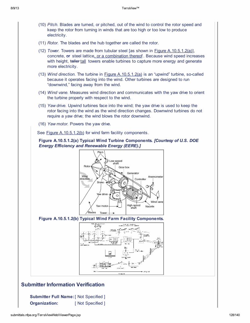
8/9/13 TerraView™
submittals.nfpa.org/TerraViewWeb/ViewerPage.jsp 128/140
(10) Pitch. Blades are turned, or pitched, out of the wind to control the rotor speed andkeep the rotor from turning in winds that are too high or too low to produceelectricity.
(11) Rotor. The blades and the hub together are called the rotor.
(12) Tower. Towers are made from tubular steel [as shown in Figure A.10.5.1.2(a)],concrete, or steel lattice, or a combination thereof . Because wind speed increaseswith height, taller tall towers enable turbines to capture more energy and generatemore electricity.
(13) Wind direction. The turbine in Figure A.10.5.1.2(a) is an “upwind” turbine, so-calledbecause it operates facing into the wind. Other turbines are designed to run“downwind,” facing away from the wind.
(14) Wind vane. Measures wind direction and communicates with the yaw drive to orientthe turbine properly with respect to the wind.
(15) Yaw drive. Upwind turbines face into the wind; the yaw drive is used to keep therotor facing into the wind as the wind direction changes. Downwind turbines do notrequire a yaw drive; the wind blows the rotor downwind.
(16) Yaw motor. Powers the yaw drive.
See Figure A.10.5.1.2(b) for wind farm facility components.
Figure A.10.5.1.2(a) Typical Wind Turbine Components. [Courtesy of U.S. DOEEnergy Efficiency and Renewable Energy (EERE).]
Figure A.10.5.1.2(b) Typical Wind Farm Facility Components.
Submitter Information Verification
Submitter Full Name: [ Not Specified ]
Organization: [ Not Specified ]

8/9/13 TerraView™
submittals.nfpa.org/TerraViewWeb/ViewerPage.jsp 129/140
Street Address:
City:
State:
Zip:
Submittal Date: Tue May 28 13:22:41 EDT 2013
Committee Statement
CommitteeStatement:
Provides a description of technology designs associated with wind turbineequipment and structures to assist document users of current technologies.
ResponseMessage:
First Revision No. 85-NFPA 850-2013 [ Section No. A.11.1 ]
8/9/13 TerraView™
submittals.nfpa.org/TerraViewWeb/ViewerPage.jsp 130/140
A.11.1
Solar Plants. Solar plants use the energy of the sun to produce electrical power. Theprocess used in current commercial utility–scale applications typically involves one oftwo basic technologies:
(1) Photovoltaic (PV) solar power that is associated with the use of PV panels invarious arrays in which energy from the sun is converted to dc electrical energy ineach of the panels that is subsequently converted to ac power for delivery to thegrid.
(2) Concentrated solar power (CSP) that involves the production of steam via a heattransfer mechanism and then using the steam to drive a steam turbine generator.
The process most commonly used in current commercial applications of solar generatingtechnology involves the heating of HTF in the solar fields to temperatures above 700°F(371°C). The HTF is heated in a network of stainless steel tubes that are located at thefocal point of the solar collection assemblies (SCAs). The SCAs consist of individuallycurved mirrors mounted on a steel truss frame and arranged in a parabolic shape. EachSCA could be as long as 80 ft (24.4 m) and up to 20 ft (6.1 m) wide. In a given solar field,there can be several hundred SCAs typically arranged in quadrants, with aisles betweenthem.
The SCA mirrors are computer controlled. Each SCA has a solar sensor and aninclinometer. Computers in the control room calculate the angle of the sun, which is thenrelayed to the SCA controllers. These, in turn, adjust the position of the SCAs to matchthat of the sun and automatically track the sun as it moves across the sky in a westerlydirection.
The HTF heating tubes are surrounded by a glass envelope with a vacuum in theinterstitial space. The fluid is moved through a given field by HTF pumps that bring theheated fluid to the power plant where, in steam generators (heat exchangers with theHTF on the primary side and water/steam on the secondary side), the hot fluid thenflashes water to steam. The steam is then used to drive one or more steam turbinegenerators. Other than the aforementioned heat exchangers, the steam side is similar tomost traditional steam turbine generator installations.
To augment the heating of the HTF, each solar generating unit is typically provided withauxiliary natural gas–fired HTF heaters. At the end of the day, as the amount of sunlightavailable decreases, or during cloudy days, the heaters are operated as needed tomaintain adequate HTF temperatures. Solar plants also typically have an ullage systemthat is used for removing impurities and water from the HTF to a separate ullage vessel.This vessel is then emptied into a truck-mounted tank for later disposal.
Submitter Information Verification
Submitter Full Name: [ Not Specified ]
Organization: [ Not Specified ]
Street Address:
City:
State:
Zip:
Submittal Date: Tue May 28 13:57:21 EDT 2013
Committee Statement
8/9/13 TerraView™
submittals.nfpa.org/TerraViewWeb/ViewerPage.jsp 131/140
CommitteeStatement:
This annex language provides document users with a description of PV and CPSsolar plants to assist in understanding the common technologies used in these solargenerating plants.
ResponseMessage:
First Revision No. 86-NFPA 850-2013 [ New Section after A.11.3 ]
A.11.3.1
Photovoltaic (PV) technology involves the conversion of solar radiation into dc electricityusing semiconductors that exhibit the photovoltaic effect. This conversion takes place ina PV solar cell that is made of various materials demonstrating photovoltaic propertiesand employing various technologies (e.g., crystalline silicon, thin film, etc.). Solar cellsare assembled to form a solar panel, and multiple panels are put together to form a solarmodule. PV modules are installed on steel support structures arranged in long rowscalled strings that are adequately spaced to avoid “shading” of one from another. In thenorthern hemisphere, PV modules typically face south and are tilted according to thelatitude of the PV site to maximize the solar radiation energy available to the module.Frequently, computer-controlled tracking systems are used to rotate the PV strings on asingle axis as necessary to follow the movement of the sun throughout the day.
PV modules/strings are connected electrically in series and parallel and thenconnected by dc cabling to inverters that convert dc power into ac power. The number ofinverters will depend on the size and layout of the PV site. The ac power produced inthe inverters is then directed through a step-up transformer to a medium-voltage (e.g.,24 KV) ac cabling and delivered to a local substation where a plant step-up transformerraises the voltage to match that of the grid being served.
Concentrated photovoltaic (CPV) technology uses optic lenses/receptors to concentratesunlight onto high-performance solar cells, thus increasing the electricity generated.The high-performance cells are then arranged on panels that are mounted to steelsupport structures that can be moved by dual-axis tracking systems to maximize thebenefit of each ray of sunlight. Modules typically have their own inverter and are,otherwise, electrically connected in a manner similar to that employed in a flat-panelPV plant. The routing of electrical power out of a CPV plant is similar to that of a PVplant.
Submitter Information Verification
Submitter Full Name: [ Not Specified ]
Organization: [ Not Specified ]
Street Address:
City:
State:
Zip:
Submittal Date: Tue May 28 14:08:10 EDT 2013
8/9/13 TerraView™
submittals.nfpa.org/TerraViewWeb/ViewerPage.jsp 132/140
Committee Statement
CommitteeStatement:
This annex language provides document users with a description of PV and CPSsolar plants to assist in understanding the common technologies used in these solargenerating plants.
ResponseMessage:
First Revision No. 117-NFPA 850-2013 [ New Section after A.13.3 ]
A.14.5.3.1
Fires occurring where a generator is in operation are caused by an electrical fault in thegenerator. Not all faults result in fire. Electrical protection should quickly isolate thegenerator following detection of a fault. Generator fires are low-frequency events. Firesoccurring in generators with thermoplastic insulation (i.e., asphalt, cloth ribbon,polyester) have resulted in self-supporting fires. Damage and downtime have beenreduced by the use of fire suppression systems. Fires in generators with thermosetinsulation (i.e., fiberglass, epoxy resin) have been less frequent. Incidents have beenreported where self-sustaining fire did not occur and operation of a fire suppressionsystem did not result in reduction of damage. There have been other incidents wheregenerator protection schemes failed to isolate the unit electrically (the unit remainedenergized). This fault energy was high enough to result in a self-sustaining fire. Theoperation of a fire suppression system limited damage and reduced the amount of timethe generator was out of service.
Submitter Information Verification
Submitter Full Name: [ Not Specified ]
Organization: [ Not Specified ]
Street Address:
City:
State:
Zip:
Submittal Date: Wed Jun 05 10:46:16 EDT 2013
Committee Statement
Committee Statement: Incorporated from NFPA 851.
Response Message:
8/9/13 TerraView™
submittals.nfpa.org/TerraViewWeb/ViewerPage.jsp 133/140
First Revision No. 116-NFPA 850-2013 [ New Section after A.13.9 ]
A.14.3.2
When fire heats air and introduces products of combustion into the air in tunnels and inunderground hydroelectric plants, the ventilation conditions that existed while the airwas cold are altered. Frictional resistance to flow of heated air containing products ofcombustion is much greater than frictional resistance to flow of cold air that does notcontain products of combustion. In the event of mild heating, increased resistance toflow would decrease the rate of ventilation. Then, after the fire is contained and the air iscooled, the air and smoke could be evacuated. Therefore, considerations for the healthand safety of people underground should cause the designers to increase the rate ofevacuating hot air containing smoke. As the fire underground increases the temperatureof the air, ventilation flow can be reversed. The cooler ventilating air can flow in onedirection occupying much of the lower spaces of tunnels while plumes of heated air flowrapidly outward from the area of the fire beneath the tunnel ceiling in the oppositedirection from, and above, the mass of cooler air. The designer should then consider thestratification of air flow, the numerous nodes or junctures between tunnels and shafts,the likely frictional resistances with and without fire, and the placement and capacitiesof the fans and firestops. Some useful information is available in the proceedings ofSession XI, Fires , of the 2nd International Mine Ventilation Congress. The designer isadvised to be thoroughly familiar with Chapter 41, Fire and Smoke Control, in theASHRAE Handbook .
Submitter Information Verification
Submitter Full Name: [ Not Specified ]
Organization: [ Not Specified ]
Street Address:
City:
State:
Zip:
Submittal Date: Wed Jun 05 10:43:11 EDT 2013
Committee Statement
Committee Statement: Incorporated from NFPA 851.
Response Message:
8/9/13 TerraView™
submittals.nfpa.org/TerraViewWeb/ViewerPage.jsp 134/140
First Revision No. 118-NFPA 850-2013 [ New Section after A.13.9 ]
A.14.5.2.4
When areas or rooms are located beneath areas protected by CO 2 (or other
extinguishing gases), consideration should be given in the design for the possiblesettling of the gas to lower levels and its effect on personnel who might be in theseareas.
Submitter Information Verification
Submitter Full Name: [ Not Specified ]
Organization: [ Not Specified ]
Street Address:
City:
State:
Zip:
Submittal Date: Wed Jun 05 10:49:00 EDT 2013
Committee Statement
Committee Statement: Incorporated from NFPA 851.
Response Message:
8/9/13 TerraView™
submittals.nfpa.org/TerraViewWeb/ViewerPage.jsp 135/140
First Revision No. 119-NFPA 850-2013 [ New Section after A.15.8.1 ]
Submitter Information Verification
Submitter Full Name: [ Not Specified ]
Organization: [ Not Specified ]
Street Address:
City:
State:
Zip:
Submittal Date: Wed Jun 05 10:52:29 EDT 2013
Committee Statement
Committee Statement: Incorporated from NFPA 851.
Response Message:

8/9/13 TerraView™
submittals.nfpa.org/TerraViewWeb/ViewerPage.jsp 136/140
First Revision No. 123-NFPA 850-2013 [ New Section after D.2.12 ]
D.2.13 Hydroelectric Plant Generator.
In 2006, a generator fire occurred at a 1272 MW hydroelectric generating plant inCanada. Internal arcing occurred in a 106 MW generator used for base load and exportpower. Fuel for the fire was the electrical insulation. The generator was protected withsmoke detection and a water deluge system. The ignition source was an electrical faultcaused by the fracture of a stator top core clamping finger that fractured and exited fromunder the core clamping plate and bounced through the air gap. This resulted inelectrical short circuits between the core and the windings and ignited the circuit ringbus and asphalt-insulated windings. The generator tripped by unit differential and splitphase protection. Smoke detection operated and the water deluge system tripped,which extinguished the fire.
Physical damage was $1.2 million, which included 53 out of 600 stator coils that wereseverely damaged, in addition to several rotor field poles. The cost of lost productiondue to the outage was $7.8 million.
This incident illustrates the benefit of providing automatic deluge protection for generatorwindings with insulation that does not self-extinguish when de-energized.
Submitter Information Verification
Submitter Full Name: [ Not Specified ]
Organization: [ Not Specified ]
Street Address:
City:
State:
Zip:
Submittal Date: Thu Jun 06 08:42:05 EDT 2013
Committee Statement
Committee Statement: Incorporated from NFPA 851.
Response Message:
First Revision No. 61-NFPA 850-2013 [ New Section after E.1 ]

8/9/13 TerraView™
submittals.nfpa.org/TerraViewWeb/ViewerPage.jsp 137/140
E.2 Organization and Detail.
Where compliance to NFPA 850 is clear, only a brief description is needed. Wherethere is deviation from NFPA 850 guidance, more detail is required regarding the fire riskevaluation and decision process.
The following is a general heading index for an NFPA 850 Fire Protection Design BasisDocument:
(1) Executive summary
(2) Stakeholder goals and objectives ( 4.2.2 )
(3) Assumptions, if applicable
(4) Project description ( 4.3.2 )
(5) Codes and standards ( 4.3.1 )
(6) General arrangement/plant layout ( 5.1 )
Fire areas, fire barriers/openings, hydrogen, transformers
(1) Life safety ( 5.2 )
(2) Building construction materials ( 5.3 )
(3) Smoke and heat venting ( 5.4 )
(4) Containment and drainage ( 5.5 )
(5) Emergency lighting
(6) Lightning protection
(7) General fire protection (Chapter 6 )
Water supply, pumps, tanks, underground, hydrants, standpipes, fire alarm systems,etc.
(1) Hazard protection (Chapters 7 through 14 )
Submitter Information Verification
Submitter Full Name: [ Not Specified ]
Organization: [ Not Specified ]
Street Address:
City:
State:
Zip:
Submittal Date: Wed May 22 13:56:23 EDT 2013
Committee Statement
CommitteeStatement:
Provides guidance for the organization of the DBD and the level of detailneeded.
Response Message:
8/9/13 TerraView™
submittals.nfpa.org/TerraViewWeb/ViewerPage.jsp 138/140
First Revision No. 103-NFPA 850-2013 [ Section No. F.1.1 ]
F.1.1 NFPA Publications.
National Fire Protection Association, 1 Batterymarch Park, Quincy, MA 02169-7471.
NFPA 12, Standard on Carbon Dioxide Extinguishing Systems, 2008 2015 edition.
NFPA 13 , Standard for the Installation of Sprink ler Systems , 2013 edition.
NFPA 30, Flammable and Combustible Liquids Code, 2015 edition.
NFPA 54 , National Fuel Gas Code , 2015 edition.
NFPA 56 , Standard for Fire and Explosion Prevention During Cleaning and Purging ofFlammable Gas Piping Systems , 2014 edition.
NFPA 58, Liquefied Petroleum Gas Code, 2015 edition.
NFPA 59, Utility LP-Gas Plant Code, 2015 edition.
NFPA 59A, Standard for the Production, Storage, and Handling of Liquefied Natural Gas(LNG), 2013 edition .
NFPA 80A, Recommended Practice for Protection of Buildings from Exterior FireExposures, 2013 edition .
NFPA 85, Boiler and Combustion Systems Hazards Code, 2007 2012 edition.
NFPA 101®, Life Safety Code®, 2009 2015 edition.
NFPA 497 , Recommended Practice for the Classification of Flammable Liquids,Gases, or Vapors and of Hazardous (Classified) Locations for Electrical Installations inChemical Process Areas , 2012 edition.
NFPA 600, Standard on Industrial Fire Brigades, 2010 2015 edition.
NFPA 1561, Standard on Emergency Services Incident Management System, 2008 2014edition.
Submitter Information Verification
Submitter Full Name: [ Not Specified ]
Organization: [ Not Specified ]
Street Address:
City:
State:
Zip:
Submittal Date: Fri May 31 13:42:26 EDT 2013
Committee Statement
Committee Statement: Revised edition dates to comply with the manual of styles
Response Message:
8/9/13 TerraView™
submittals.nfpa.org/TerraViewWeb/ViewerPage.jsp 139/140
First Revision No. 125-NFPA 850-2013 [ New Section after F.1.2.2 ]
F.1.2.3 ASHRAE Publications.
ASHRAE, 1791 Tullie Circle, N.E., Atlanta, GA 30329-2305.
ASHRAE Handbook — Chapter 41, Fire and Smoke Control , 2013.
Submitter Information Verification
Submitter Full Name: [ Not Specified ]
Organization: [ Not Specified ]
Street Address:
City:
State:
Zip:
Submittal Date: Thu Jun 06 08:46:05 EDT 2013
Committee Statement
Committee Statement: Incorporated from NFPA 851.
Response Message:

8/9/13 TerraView™
submittals.nfpa.org/TerraViewWeb/ViewerPage.jsp 140/140
First Revision No. 124-NFPA 850-2013 [ Section No. F.1.2.9 ]
F.1.2.11 Other Publications.
“Fire Tests in Ventilated Rooms Extinguishment of Fire in Grouped Cable Trays,” ElectricPower Research Institute, EPRI NP-2660, December 1982.
“Fire Tests of Automatic Sprinkler Protection for Oil Spill Fires,” Factory Mutual ResearchCorp., September 9, 1957.
Proceedings of Session XI, Fires”, 2nd International Mine Ventilation Congress, 1980.
“Report on the Performance of Fire Fighting Equipment Utilizing Water Spray WhenInitiated by Heat Detecting Cable,” Central Electricity Generating Board, February 1978.
“Sprinkler and Water Spray Tests on Turbine Oil Fires,” Industrial Mutual Insurance Co.,December 1979.
“Sprinkler Tests in a Cable Duct (Tunnel) in Rautaraukki Oy's Factory in Raahe,”Industrial Mutual Insurance Co., 1975.
Technical Report ID 0003018250, “Turbine Fire Protection,” C. Wieczorek, FM Global,April 2004.
Technical Report ID 003013258, “Investigation into Protection of Flammable Liquids inLarge Plastic Totes — — Phases I and II,” R. Dean, FM Global, December 2004.
“Tests of Candidate Glass Fiber-Reinforced Stack Liner Materials,” Factory MutualResearch Corporation, July 1975.
Submitter Information Verification
Submitter Full Name: [ Not Specified ]
Organization: [ Not Specified ]
Street Address:
City:
State:
Zip:
Submittal Date: Thu Jun 06 08:44:08 EDT 2013
Committee Statement
Committee Statement: Incorporated from NFPA 851.
Response Message:


![[ICorr초빙교육] Insulation & Fireproofing Inspector 초빙교육 개최 … · 2013. 12. 24. · 나. ICorr 방화코팅검사원 인증교육과정(Fireproofing Inspector Level](https://img.pdfslide.us/doc/110x75/5fee12d355a57244343ce486/icorreeoe-insulation-fireproofing-inspector-eeoe-eoeoe.jpg)