Embed Size (px)
Citation preview

EIE209 Basic Electronics
First-order transient
Contents• Inductor and capacitor• Simple RC and RL circuits• Transient solutions
Prof. C.K. Tse: First Order Transient

2Prof. C.K. Tse: First Order Transient
Constitutive relation® An electrical element is defined by its relationship between v and i.
This is called constitutive relation. In general, we write
® For a resistor,® v = i R
® The constitutive relation of a resistor has no dependence upon time.
†
v = f (i ) or i = g(v)
+ v –
i

3Prof. C.K. Tse: First Order Transient
Capacitor and inductor
+ vc –
icThe constitutive relation of alinear capacitor is:
The constitutive relation of alinear inductor is:
†
ic = Cdvc
dt
†
vL = LdiLdt
+ vL –
iL
C
L
where the proportionalityconstant C is capacitance(unit is farad or F)
where the proportionalityconstant L is inductance(unit is henry or H)

4Prof. C.K. Tse: First Order Transient
What happens if a circuit has C and/or L?
® The circuit becomes dynamic. That means:
® Its behaviour is a function of time.
® Its behaviour is described by a (set of) differentialequation(s).
® It has a transient response as well as a steady state.

5Prof. C.K. Tse: First Order Transient
Resistive circuits have no transient® Consider a resistive circuit.
® When the switch is turned on,the voltage across R becomes Vimmediately (in zero time).
® v = V = i R for all t > 0
® i = V / R for all t > 0

6Prof. C.K. Tse: First Order Transient
A simple first-order RC circuit®Let us consider a very simple dynamic circuit, whichcontains one capacitor.
®After t = 0, the circuit is closed. So, we can easily write
®and
®Thus, we have
®Thus, we have
®If the initial condition is vC(0+) = 0, then A = –Vo.
®Thus, the solution is
fi
Vo for t>0

7Prof. C.K. Tse: First Order Transient
Transient response of the RC circuit®Once we have the capacitor voltage, we can findanything.
®Starting with
®We can derive the current as
®We see the solution typically has a TRANSIENTwhich dies out eventually, and as t tends to ∞, thesolution settles to a steady state.
time constant

8Prof. C.K. Tse: First Order Transient
A simple first-order RL circuit®Consider a RL circuit.®Before t = 0, the switch is closed (turned on).Current goes through the switch and nothing goesto R and L. Initially, iL(0–) = 0.®At t = 0, the switch is opened. Current goes to Rand L.®We know from KCL that Io = iR + iL for t > 0, i.e.,
®The constitutive relations give®Hence,® fi
®The solution is
From the initial condition, wehave iL(0–) = 0. Continuity ofthe inductor current means thatiL(0+) = iL(0–) = 0. Hence,
A = –Io
Thus,
9Prof. C.K. Tse: First Order Transient
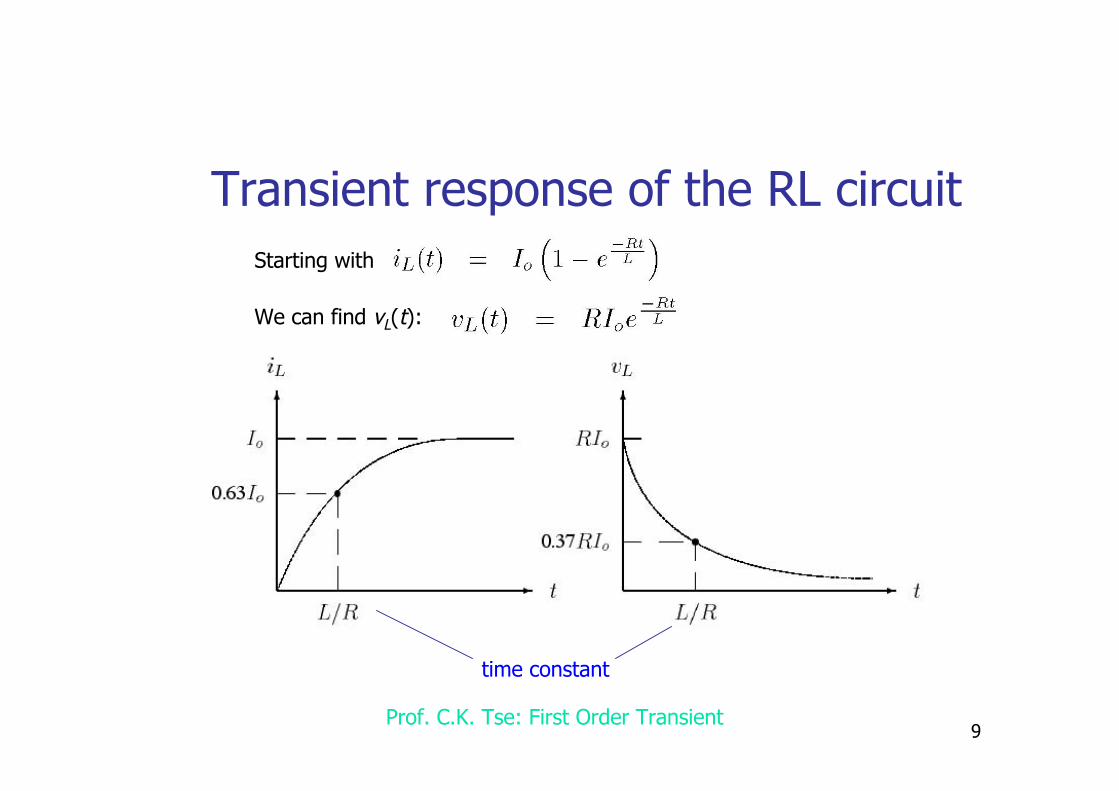
Transient response of the RL circuit® Starting with
® We can find vL(t):
time constant

10Prof. C.K. Tse: First Order Transient
Observation — first-order transients® First order transients are always like these:

11Prof. C.K. Tse: First Order Transient
Let’s do some math
0
5
x(t)
t
x(t) = 5(1 – e–t/t)
0
5
x(t)
t
x(t) = 5 e–t/t
0
6
x(t)
t1
x(t) = 1 + 5(1 – e–t/t)
x(t) = 1 + 5 e–t/t
0
5
x(t)
t
–2
x(t) = –2 + 7(1 – e–t/t)
0
4
x(t)
t
–3
0
6
x(t)
t1
x(t) = –3 + 7 e–t/t

12Prof. C.K. Tse: First Order Transient
General first-order solution
NO NEED TO SOLVE ANY EQUATION, just find
1. the starting point of capacitor voltage or inductor current2. the ending point of ………… ………. ……. ………. ……….3. the time constant t

13Prof. C.K. Tse: First Order Transient
Finding t
For the simple first-order RC circuit, t = C R.For the simple first-order RL circuit, t = L / R.
The problem is
Given a first-order circuit (which may look complicated),how to find the equivalent simple RC or RL circuit.

14Prof. C.K. Tse: First Order Transient
A quick way to find tSince the time constant is independent of the sources, we first of all setall sources to zero. That means, short-circuit all voltage sources and open-circuit all current sources. Then, reduce the circuit to
+–
R1
R2 C
R1
R2 C CR1 || R2
CeqReq Req Leqeither or
Example:
t = C (R1 || R2)

15Prof. C.K. Tse: First Order Transient
Example 1 (boundary conditions given)Find vc(t) for t > 0 without solving anydifferential equation.
Step 1: initial point (given)
vc(0–) = 50 V is known (but not what we want).Continuity of cap voltage guarantees thatvc(0+) = vc(0–) = 50 V.
Step 2: final point (almost given)
vc(∞) = –20 V.
Step 3: time constant
The equivalent RC circuit is:
Thus, t = CR.
Answer is:
vc(t) = –20 + 70 e–t/CR
0
50
t–20
16Prof. C.K. Tse: First Order Transient
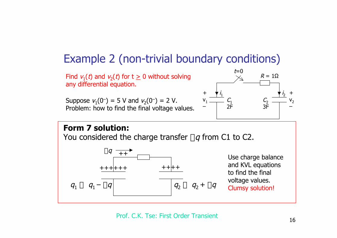
Example 2 (non-trivial boundary conditions)Find v1(t) and v2(t) for t > 0 without solvingany differential equation.
+v1–
+v2–
C12F
C23F
i1
R = 1Ωt=0
i2Suppose v1(0–) = 5 V and v2(0–) = 2 V.Problem: how to find the final voltage values.
Form 7 solution:You considered the charge transfer Dq from C1 to C2.
++++++ ++++
++Dq
q1 fi q1 – Dq q2 fi q2 + Dq
Use charge balanceand KVL equationsto find the finalvoltage values.Clumsy solution!

17Prof. C.K. Tse: First Order Transient
Example 2 (elegant solution)
We need not consider CHARGE!
Step 1: initial point (given)
v1(0–) = 5 V and v2(0–) = 2 V are known.Continuity of cap voltage guarantees thatv1(0+) = 5 V and v2(0+) = 2 V.
Step 2: final point (non-trivial)
C1: for all t
C2: for all t
After t>0, we have i1 = –i2, i.e.,
+v1–
+v2–
C12F
C23F
i1
R = 1Ωt=0
†
i1 = 2dv1
dt
i2 = 3dv2
dt
†
2dv1
dt+ 3
dv2
dt= 0
fi 2v1(t) + 3v2(t) = K for all t > 0.
i2
Integration constant
At t = 0+, this equation means2*5 + 3*2 = K. Thus, K = 16.Thus,2v1(t) + 3v2(t) = 16 for t > 0.
At t =∞, we have v1(∞)=v2(∞)from KVL. Hence, 2v1(∞)+3v1(∞)=16fi v1(∞)=v2(∞)=16/5 V.

18Prof. C.K. Tse: First Order Transient
Example 2 (elegant solution)
Step 3: time constant
The circuit after t = 0 is
This can be reduced to
The time constant is
+v1–
+v2–
C12F
C23F
i1
R = 1Ω
i2
C1 C2
C1 +C2
= 6/5 F R = 1Ω
†
t =C1C2
C1 + C2¥R =
65
s

19Prof. C.K. Tse: First Order Transient
Example 2 (answer)
5V
16/5=3.2V
v1
t
2V
16/5=3.2V
v2
t
†
v1(t ) = 3.2 +1.8e-5t / 6 V
†
v2(t) = 2 + 1.2(1- e-5t / 6) V
We can also find the current by
†
i(t) =v1(t) -v2 (t)
R= 3e -5t / 6 A
20Prof. C.K. Tse: First Order Transient
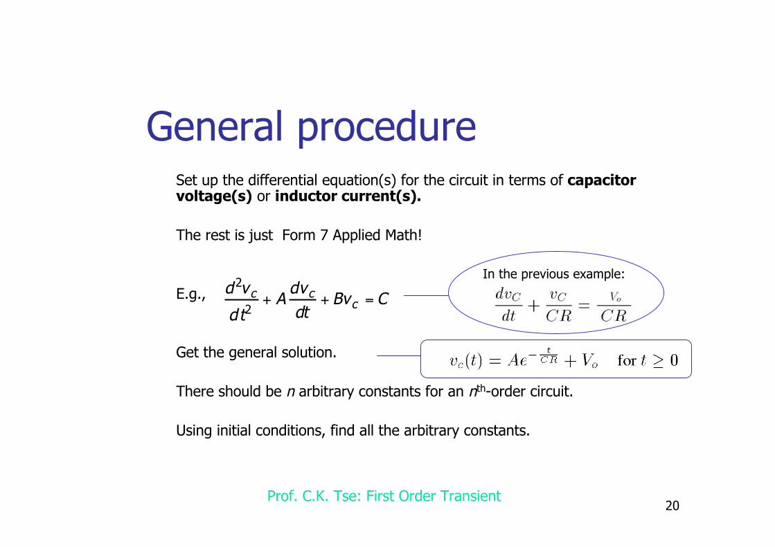
General procedure® Set up the differential equation(s) for the circuit in terms of capacitor
voltage(s) or inductor current(s).
® The rest is just Form 7 Applied Math!
® E.g.,
® Get the general solution.
® There should be n arbitrary constants for an nth-order circuit.
® Using initial conditions, find all the arbitrary constants.
†
d2vc
dt2+ A
dvc
dt+ Bvc = C
In the previous example:

21Prof. C.K. Tse: First Order Transient
Basic question 1®Why must we choose capacitor voltage and inductor current as thevariable(s) for setting up differential equations?
® Never try to set differential equation in terms of other kinds of variables!
®Answer:®Capacitor voltages and inductor currents are guaranteed to be CONTINUOUSbefore and after the switching. So, it is always true that
†
dvR
dt+ kvR = Vo
†
vC (0-) = vC (0+) and iL (0-) = iL (0+)
22Prof. C.K. Tse: First Order Transient
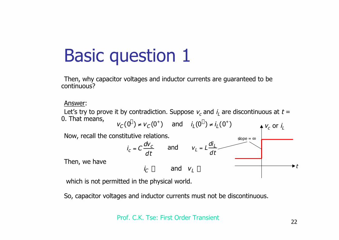
Basic question 1®Then, why capacitor voltages and inductor currents are guaranteed to becontinuous?
®Answer:®Let’s try to prove it by contradiction. Suppose vc and iL are discontinuous at t =0. That means,
®Now, recall the constitutive relations.
®Then, we have
®So, capacitor voltages and inductor currents must not be discontinuous.
†
vC (0-) ≠ vC (0+) and iL (0-) ≠ iL (0+)
†
ic = Cdvc
dt
†
vL = LdiLdt
and
†
iC Æ • and vL Æ •
which is not permitted in the physical world.
vc or iL
t
slope = ∞

23Prof. C.K. Tse: First Order Transient
Basic question 2®How to get the differential equation systematically for any circuit?
®For simple circuits (like the simple RC and RL circuits), we can get it by an adhoc procedure, as in the previous examples. But, if the circuit is big, it seemsrather difficult!
®Hint:®Graph theory. (See Chapter 8 of my book)