Embed Size (px)
Citation preview

(NASA-TM-109242) NASA' S FIRST
IN-SPACE OPTICAL GYROSCOPE: A
TECHNOLOGY EXPERIMENT ON THE X RAY
TIMING EXPLORER SPACECRAFT (NASA)
7 p
N94-10667
Unclas
G3135 0183105
https://ntrs.nasa.gov/search.jsp?R=19940006212 2020-02-24T04:01:02+00:00Z


,lp'_
NASA-TN-1092421953-09
NASA's first in-space optical gyroscope
A technology experiment on the X-ray Timing Explorer spacecraft
Glenn Unger, David M. Kaufman, Michael K.rainak
NASA Goddard Space Flight Center, MC 715.2, Greenbelt, Maryland 20771
Glenn Sanders
Honeywell, MC 2J27A1, Phoenix, Arizona 85036
Bill Taylor
Honeywell, MC 218-3, Clearwater, Florida 34624
Norman R. Schulze
X4 A
//v'- z- 7Pt/
NASA Headquarters�Code QE, Washington D.C., 20546
ABSTRACT
We describe a technology experiment on the X-ray Timing Explorer spacecraft to determine the
feasibility of Interferometric Fiber Optic Gyroscopes for space flight navigation. The experimentconsists of placing a medium grade fiber optic gyroscope in parallel with the spacecraft's inertialreference unit. The performance of the fiber optic gyroscope will be monitored and compared to the
primary mechanical gyroscope's performance throughout the two-year mission life.
1. INTRODUCTION
Interferometric Fiber optic Gyroscopes (IFOGs) are rotation sensors used for commercial aircraft
and cruise missile navigation, l, 2 IFOGs are a small, solid state, light weight, low voltage, and low
power alternative to mechanical gyros. These attributes make the IFOG ideal for space flightnavigation use. IFOGs have the potential for > 15 year reliability. In addition, the IFOG measurementsensitivity can be scaled by adjusting the fiber loop diameter and/or the number of turns. As a result,IFOGs are capable of measuring incremental angles and rotation rates to a high level of accuracy.
NASA/Goddard Space Flight Center iNASA]GSFC) and Honeywell are teaming to fly an IFOG
experiment on a NASA spacecraft. The X-ray Timing Explorer 3 (XTE) has been identified as the nearterm target of opportunity for the IFOG experiment. A closed-loop IFOG IRU (Inertial ReferenceUnit) will be placed on the XTE spacecraft as a separate, but distinct experiment- -
The goal is to transfer the [FOG technology from aircraft and missile applications to routineNASA space flight use. This offers great benefits. NASA obtains a more cost efficient, reliable'
: technology for space flight navigation with a number of proven suppliers and the navigation instrumentmarket is enhanced and expanded for military and commercial suppliers.
The main objective of the XTE IFOG experiment is to prove the long term feasibility and
reliability of the IFOG technology for space navigation. Other objectives are to: (1) establish a mediumperformance space qualified IFOG IRU specification for the NASA/GSFC Small Explorer (SMEX),Earth probe, and Explorer class spacecraft such as XTE, Tropical Rainfall Measuring Mission(TRMM), Far Ultraviolet Spectroscopic Explorer (FUSE,) etc., (2) provide flight heritage for a vendor-
\\

J t

- .-: :' "-' "......... 1953:09
supported optical guidance and control component for future spacecraft, (3) increase reliability ofNASA spacecraft to support several medium and small class science missions, and (4) develop lowcost, reliable on-shore market suppliers to support NASA missions.
We will discuss in the following sections the XTE project, science objectives, and pointing
requirements; [FOG experiment; space-based and ground-based data processing; IFOG-to-XTEinterface; and [FOG description and performance.
2. X-RAY TIMING EXPLORER
A Delta II will be launched from Kennedy Space Center (KSC) and carry the XTE into a 500 kmto 600 km orbit with a 23 degree inclination. The XTE will be launched no later than April 1996 with a
launch goal of August 1995. The mission life is anticipated to be greater than two years. XTE will
weigh less than 7200 pound and use less than 800 Watts. XTE's three primary instruments are the AllSky Monitor (ASM), Proportional Counter Array (PCA), and High Energy X-ray Timing Experiment(HEXTE.) The ASM is being developed at Massachusetts Institute of Technology, the PCA atNASA/GSFC, and the HEXTE at University of California. XTE's science objective is to monitor and
study 2 keV to 200 keV energy regions in the sky. The spacecraft must provide 0. I degree pointing toany celestial source, 0.036 degree pointing knowledge, and less than 0.0083 degree jitter (3 sigma.)
3. [FOG IRU EXPERIMENT
The proposed experiment will compare the performance of the [FOG with that of the XTE'sprimary gyroscope, a mechanical gyroscope, for at least 2 years. By comparing the primary gyro'sdetermined attitude with the IFOG's determined attitude, the IFOG's long-term reliability can bemeasured. The XTE On-Board Computer (OBC) and GSFC ground-based computers determine the
spacecraft attitude from the XTE primary IRU data. However, only the GSFC ground-based computerswill be used for spacecraft attitude determination using the IFOG IRU data.
4. DATA PROCESSING
Compensated incremental angle data from the [FOG IRU and primary mechanical gyro based IRUwill be read by the XTE on-board computer at a 4 Hz rate. [FOG voltages, temperatures, and statuswill be read at a 0.5 Hz rate. The [FOG IRU will be read immediately before the primary gyro. The
data flow for the two gyros will be different. In particular, the position or incremental angle data flow
for both gyros is described in the following paragraphs.
The IFOG IRU data packet will be dumped to the Spacecraft Command and Data HandlingSoftware for formatting. The packet format adheres to the standards set forth by the ConsultativeCommittee for Space Data Systems (CCSDS.) After the [FOG IRU data is formatted it will betelemetered to the GSFC Flight Operation Team (FOT.) The FOT is responsible for retrieving all XTE
telemetry, performing trending analysis (i.e. voltage vs. time), transferring data to the Flight DynamicsFacility (FDF), and data storage. The FDF is responsible for On-board Computer (OBC) AttitudeDetermination and Validation (AD&V.) During each XTE OBC AD&V, the FDF will measure
residual statistics - a process that defines vectors and calculates vector differences for the primary gyroand [FOG relative to the star sensor. Also, the FDF will corn.pare the IFOG determined attitude with
primary gyro determined attitude. The FDF attitude determinataon process is similar to that used by theXTE Attitude Control System (ACS) OBC. Using the star tracker and gyroscope input, a Kalman filter
determines an error and propagates a new spacecraft attitude.
........... <- ,- "

1953-09• : ,'f ;:- ::" S_-IEET
Unlike the IFOG's data processing, the XTE Attitude Control System On-Board Computer will
use the primary gyro data to determine the spacecraft's attitude. The XTE's star sensor data and theprimary gyro's incremental angle data will be input to a Kalman filter. The filter is implemented withthe XTE OBC. The OBC will determine the delta quaternion from which the new attitude is
propagated. The attitude, star sensor data, and incremental angle are among the many types of data thatare telemetered to earth,
5. IFOG INTERFACE
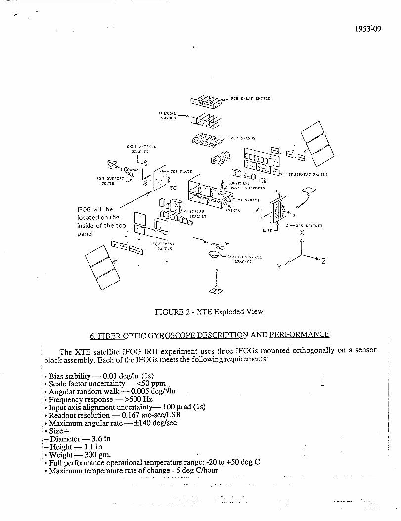
The IFOG IRU will be located on the top inside panel on the spacecraft side (see figure 1 and 2.)The ]:FOG is less than 10 pounds and is 7" wide, 7" high, and 10" deep. The thermal environment isbetween -10°C and +40°C. No thermal heaters are necessary. The XTE has three MIL-STD 1773
buses: the spacecraft, instrument, and ACS. The IFOG will interface to the ACS's bus. The Non-essential Power Bus will supply +28 V DC to the ]:FOG IRU. The IFOG IRU will also have access to a
+28 V pulse that can turn-on and turn-off its internal switch. The relay allows the supply voltage toreach the IFOG IRU electronics. The IFOG IRU worst case power consumption is 30 Watts.
Z
I
IFOG v,n'll be
loczted on the
inside of the top
panel
FIGURE 1 - XTE Deployed View
j_
1953--09
Y
FIGURE 2 - XTE Exploded View
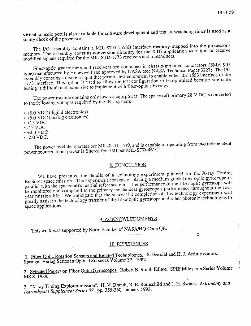
6. FIBER OPTIC GYROSCOPE DESCRIPTION AND PERFORMANCE
The XTE satellite IFOG IRU experiment uses three IFOGs mounted orthogonally on a sensor
block assembly. Each of the IFOGs meets the following requirements:
•Bias stability _ 0.01 deg/hr (Is)
Scale factor uncertainty -- <50 ppm,Angular random walk _ 0.005 deg/'qhr
• Frequency response _ >500 Hz• Input axis alignment uncertainty--- I00 grad (ls)• Readout resolution _ 0.167 arc-sec/LSB
• Maximum angular rate _ +140 deg/sec• Size- Diameter _ 3.6 in
- Height _ 1. I in:. Weight-- 300 gm.• Full performance operational temperature range: -20 to +50 deg C• Maximum temperature rate of change - 5 deg C/hour
m

1953-09
As shown in figure 3, the IFOG consists of a solid state light source, a fiber-optic directional
coupler, a Lithium Niobate (LiNbO3) integrated optic multi-function chip (MFC), the fiber sensing coil,a photodetector and signal processing electronics. The sensing coil is roughly one kilometer in length,wound on a mandrel which is nominally three inches in diameter. The MFC consists of a polarizer, two
phase modulators, and a "Y-junction" for splitting thc source light into two waves of equal intensity.The two waves, after traversing the coil in the clockwise (cw) and counter clockwise (ccw) directions,are then recombined at the "Y-junction" and then directed to the photodetector via a fused fiber-optic
directional coupler. In the absence of rotation, the cw and ccw waves see identical path lengths insidethe sensing coil, and therefore interfere constructively (maximum intensity) at the photodetector. In the
presence of rotation, the two waves experience a path length difference proportional to the rotation rate.
To measure the small phase shifts due to rotation, a standard AC bias modulation technique is
used. The optical phase difference between waves is modulated, and the photodetector output is
synchronously detected. In closed loop operation, the demodulated signal serves as an error signal fordriving the sensor back to its null condition. This is achieved by applying a phase ramp feedbacksignal to one of the phase modulators on the MFC, which in turn, introduces a phase difference into theloop equal and opposite to that caused by rotation. The feedback signal then provides a digital pulsetrain of frequency proportional tO rotation rate and an integrated output proportional to the accumulated
angle of rotation (0.167 arc second/pulse).
I Light _FCSource
" TBias Modulation in
Feedback Modulation in
Photodetector/
PreamplifierAssembly v Signal output
FIGURE 3 - IFOG Concept
7. IFOG IRU ELECTRONICS
The major IRU system subassemblies, shown in the block diagram of figure 4, are:
; • Inertial Sensor Assembly lISA)
- Fiber Optic Gyros (three)• MIB and wiring harness• IFOG Support Electronics assembly° Built-In Test (]3IT)/Control Electronics assembly
.. -..-,

.3"
.- , .-
1953-09
• Processor assembly• I/O assembly• Power Supply assembly° Chassis
IFOGELEX
I BIT/CONTROL
ELEX
CPUELEX
-GVSC
.32KPROM
.64KRAM
oWDT
J+5VDC DIG
+5VDC ANLG
+/-2.0VDC
+/-15VDC
INTERFACE
ELEX
1773
-I/O RAM
JJ LM,,-s o-1773
INTERFACE
POWER
MODULE
_ 28VDC
FIGURE 4 - Major IRU System Subassemblies
The IFOG Support Electronics assembly contains the closed-loop electronics for all three sensors.Each channel contains the bias modulation and control electronics required to close the loop. The
assembly outputs two pulse streams for each gyro -- one for a positive angular motion, and another for
a negative angular motion about the input axis of the gyro. The pulses are then accumulated on theBuilt-In Test (BIT)/control electronics assembly.
The BIT/control electronics assembly contains pulse accumulators for counting and storing pulses
from the gyro electronics. The assembly also contains a 12 bit analog-to-digi.'tal converter system for
measuring temperatures and voltages. Temperatures are used for compensating the raw pulse countsand for BIT purposes. The voltages are for monitoring purposes as a part of the BIT. _-
The IRU system contains the Honeywell radiation-hardened RH1750 processor- a MIL-STD-
1750A processor used in spaceborne computer systems designed by Honeywell. This processorcontains floating point capability, and a has a throughput capacity of 2.0 MIPS for a DAIS instructionmix using a 14 MHz clock source. The processor currently has more than 50 percent spare throughput
capacity, and more than 50 percent spare memory.
The processor assembly con_ins 32K x 16 bits of bipolar PROM that is downloaded at power-upto higher-speed RAM. The assembly contains 64K x 48 bits of static high-speed RAM. The RH1750stores data into 32 bit locations, with additional bits used for Error Detection and Correction (EDAC)
and column sparing. The bipolar PROM is powered down after downloading, conserving power. A
1953-09
virtual consoleport is also availablefor softwaredevelopmentandtest.A watchdogtimer is usedasasanitycheckof theprocessor.
The I/O assemblycontainsa MIL-STD-1553B interface memory-mappedinto the processor'smemory.The assemblycontainsconversioncircuitry for the XTE application to output or receivemodifiedsignalsrequiredfor theMIL-STD-1773receiversandtransmitters.
Fiber-optic transmittersand receiversarecontainedin chassis-mountedconnectors(SMA 905type)manufacturedby Honeywellandapprovedby NASA (seeNASA TechnicalPaper3227).TheI/Oassemblycontainsadiscreteinput thatpemaitstestequipmentto enableeitherthe 1553interfaceor the1773interface.This option is usedto allow the testconfigurationto beoptimized becauserate-tabletestingis difficult andexpensiveto implementwith fiber-opticslip rings.
Thepowermodulecontainsonly low-voltagepower.Thespacecraftprimary 28V DC is convertedto thefollowing voltagesrequiredby theIRU system:
• +5.0VDC (digital electronics)• +5.0VDC (analogelectronics)• +15VDC• -15VDC• +2.0VDC• -2.0VDC.
ThepowermoduleoperatesperMIL-STD-1539, andis capableof operatingfrom two independentpowersources.Input power is filtered for EMI perMIL-STD-461C.
.8. CONCLUSION
We have presented the details of a technology experiment planned for the X-ray Timing
Explorer space mission. The experiment consists of placing a medium grade fiber optic gyroscope inparallel with the spacecraft's inertial reference unit. The performance of the fiber optic gyroscope willbe monitored and compared to the primary mechanical gyroscope's performance throughout the two-
year mission life. We anticipate that the successful completion of this technology experiment willgreatly assist in the technology transfer of the fiber optic gyroscope and other photonic technologies to
space applications.
9. ACKNOWLEDGMENTS
This work was supported by Norm Schulze of NASAJHQ Code QE.
10. REFERENCES
1. Fiber Optic R0tatiQn Sensors and Related Technologies. S. Ezekiel and H. J. Arditty editors.
Springer Verlag Series in Optical Sciences Volume 32. 1982.
2. Selected Papers on Fiber Optic Gyroscopes. Robert B. Smith Editor. SPIE Milestone Series Volume
MS 8. 1989.
3. "X-ray Timing Explorer mission". H. V. Brandt, R. E. Rothschild and J. H. Swank. Astronomy and
Astrophysics Supplement Series 07. pp. 355-360. January 1993.
I I
Routing Slip
i is -_- .T_ i
Mail Code NameAction
Approval
Call me
Concurrence
File
Information
Investigate and AdviseNote and Forward
Note and Return
Per Request
Per Phone Conversation
Recommendation
See me
_Signature
Circulate and Destroy-
Name /2 I Tel. No. (or Code) & Ext.I
(_r other designation)
Code Z"--- JE)ate ,_.,__,, / _ --_"_
NASA FORM 26 JUN 78 PREVIOUS EDiTiONS MAY BE USED,
GPO : 1985 O - 477-116 : QL 3

% - f.J,